WO2023047676A1 - Recording medium, card, and booklet - Google Patents
Recording medium, card, and booklet Download PDFInfo
- Publication number
- WO2023047676A1 WO2023047676A1 PCT/JP2022/016419 JP2022016419W WO2023047676A1 WO 2023047676 A1 WO2023047676 A1 WO 2023047676A1 JP 2022016419 W JP2022016419 W JP 2022016419W WO 2023047676 A1 WO2023047676 A1 WO 2023047676A1
- Authority
- WO
- WIPO (PCT)
- Prior art keywords
- recording medium
- formula
- layer
- recording
- group
- Prior art date
Links
- 125000001997 phenyl group Chemical group [H]C1=C([H])C([H])=C(*)C([H])=C1[H] 0.000 claims abstract description 65
- 150000001875 compounds Chemical class 0.000 claims abstract description 58
- 238000006243 chemical reaction Methods 0.000 claims description 51
- 239000003795 chemical substances by application Substances 0.000 claims description 35
- 238000010521 absorption reaction Methods 0.000 claims description 15
- 239000002775 capsule Substances 0.000 claims description 10
- 230000001747 exhibiting effect Effects 0.000 claims description 10
- 239000001257 hydrogen Substances 0.000 claims description 10
- 229910052739 hydrogen Inorganic materials 0.000 claims description 10
- 239000004202 carbamide Substances 0.000 claims description 9
- 125000002887 hydroxy group Chemical group [H]O* 0.000 claims description 8
- 239000002253 acid Substances 0.000 claims description 5
- 125000005647 linker group Chemical group 0.000 claims description 5
- 229920005668 polycarbonate resin Polymers 0.000 claims description 4
- 239000004431 polycarbonate resin Substances 0.000 claims description 4
- 238000003860 storage Methods 0.000 abstract description 51
- 230000014759 maintenance of location Effects 0.000 abstract description 26
- 239000010410 layer Substances 0.000 description 350
- 239000000463 material Substances 0.000 description 86
- 229920005989 resin Polymers 0.000 description 84
- 239000011347 resin Substances 0.000 description 84
- KRHYYFGTRYWZRS-UHFFFAOYSA-N Fluorane Chemical compound F KRHYYFGTRYWZRS-UHFFFAOYSA-N 0.000 description 54
- 229910000040 hydrogen fluoride Inorganic materials 0.000 description 54
- 238000011156 evaluation Methods 0.000 description 42
- 150000002430 hydrocarbons Chemical group 0.000 description 40
- 239000012790 adhesive layer Substances 0.000 description 39
- 239000003094 microcapsule Substances 0.000 description 39
- 239000000758 substrate Substances 0.000 description 32
- 239000011159 matrix material Substances 0.000 description 31
- 238000012360 testing method Methods 0.000 description 31
- UHOVQNZJYSORNB-UHFFFAOYSA-N Benzene Chemical group C1=CC=CC=C1 UHOVQNZJYSORNB-UHFFFAOYSA-N 0.000 description 28
- 239000000975 dye Substances 0.000 description 24
- 239000004417 polycarbonate Substances 0.000 description 21
- 229920000515 polycarbonate Polymers 0.000 description 21
- 238000000576 coating method Methods 0.000 description 20
- 210000000282 nail Anatomy 0.000 description 20
- 239000011248 coating agent Substances 0.000 description 19
- 239000003086 colorant Substances 0.000 description 19
- 238000004040 coloring Methods 0.000 description 18
- 125000005843 halogen group Chemical group 0.000 description 18
- 238000000034 method Methods 0.000 description 18
- -1 polyethylene terephthalate Polymers 0.000 description 18
- 239000011241 protective layer Substances 0.000 description 17
- 238000012986 modification Methods 0.000 description 16
- 230000004048 modification Effects 0.000 description 16
- 229920003229 poly(methyl methacrylate) Polymers 0.000 description 16
- 239000004926 polymethyl methacrylate Substances 0.000 description 16
- 229920005992 thermoplastic resin Polymers 0.000 description 16
- 230000000694 effects Effects 0.000 description 15
- 239000004721 Polyphenylene oxide Substances 0.000 description 13
- 230000008859 change Effects 0.000 description 13
- 229920006380 polyphenylene oxide Polymers 0.000 description 12
- 229920001187 thermosetting polymer Polymers 0.000 description 12
- 125000004432 carbon atom Chemical group C* 0.000 description 11
- 125000001424 substituent group Chemical group 0.000 description 11
- 229920000122 acrylonitrile butadiene styrene Polymers 0.000 description 10
- 125000000217 alkyl group Chemical group 0.000 description 10
- 238000004519 manufacturing process Methods 0.000 description 10
- 229920000642 polymer Polymers 0.000 description 10
- ZWEHNKRNPOVVGH-UHFFFAOYSA-N 2-Butanone Chemical compound CCC(C)=O ZWEHNKRNPOVVGH-UHFFFAOYSA-N 0.000 description 9
- 239000004793 Polystyrene Substances 0.000 description 9
- 239000004800 polyvinyl chloride Substances 0.000 description 9
- IJGRMHOSHXDMSA-UHFFFAOYSA-N Atomic nitrogen Chemical compound N#N IJGRMHOSHXDMSA-UHFFFAOYSA-N 0.000 description 8
- 239000000654 additive Substances 0.000 description 8
- 239000000853 adhesive Substances 0.000 description 8
- 230000001070 adhesive effect Effects 0.000 description 8
- 150000002148 esters Chemical class 0.000 description 8
- 229910010272 inorganic material Inorganic materials 0.000 description 8
- 229920003023 plastic Polymers 0.000 description 8
- 239000004033 plastic Substances 0.000 description 8
- OKTJSMMVPCPJKN-UHFFFAOYSA-N Carbon Chemical compound [C] OKTJSMMVPCPJKN-UHFFFAOYSA-N 0.000 description 7
- 238000011161 development Methods 0.000 description 7
- 150000002596 lactones Chemical group 0.000 description 7
- 239000005020 polyethylene terephthalate Substances 0.000 description 7
- 229920000139 polyethylene terephthalate Polymers 0.000 description 7
- YCKRFDGAMUMZLT-UHFFFAOYSA-N Fluorine atom Chemical group [F] YCKRFDGAMUMZLT-UHFFFAOYSA-N 0.000 description 6
- 239000004372 Polyvinyl alcohol Substances 0.000 description 6
- 239000000956 alloy Substances 0.000 description 6
- 229910045601 alloy Inorganic materials 0.000 description 6
- 229910052799 carbon Inorganic materials 0.000 description 6
- 229920001577 copolymer Polymers 0.000 description 6
- 229910052731 fluorine Inorganic materials 0.000 description 6
- 239000011737 fluorine Substances 0.000 description 6
- 239000011147 inorganic material Substances 0.000 description 6
- 238000002844 melting Methods 0.000 description 6
- 230000008018 melting Effects 0.000 description 6
- 229910052751 metal Inorganic materials 0.000 description 6
- 239000002184 metal Substances 0.000 description 6
- 229920002492 poly(sulfone) Polymers 0.000 description 6
- 229920000728 polyester Polymers 0.000 description 6
- 229920002530 polyetherether ketone Polymers 0.000 description 6
- 229920002451 polyvinyl alcohol Polymers 0.000 description 6
- 238000002360 preparation method Methods 0.000 description 6
- 229920006942 ABS/PC Polymers 0.000 description 5
- 239000004215 Carbon black (E152) Substances 0.000 description 5
- 239000004698 Polyethylene Substances 0.000 description 5
- 239000004743 Polypropylene Substances 0.000 description 5
- VYPSYNLAJGMNEJ-UHFFFAOYSA-N Silicium dioxide Chemical compound O=[Si]=O VYPSYNLAJGMNEJ-UHFFFAOYSA-N 0.000 description 5
- 230000000996 additive effect Effects 0.000 description 5
- 230000004927 fusion Effects 0.000 description 5
- 239000011521 glass Substances 0.000 description 5
- 229930195733 hydrocarbon Natural products 0.000 description 5
- 238000005259 measurement Methods 0.000 description 5
- 239000007769 metal material Substances 0.000 description 5
- 239000003973 paint Substances 0.000 description 5
- 229920000573 polyethylene Polymers 0.000 description 5
- 229920001155 polypropylene Polymers 0.000 description 5
- QGKMIGUHVLGJBR-UHFFFAOYSA-M (4z)-1-(3-methylbutyl)-4-[[1-(3-methylbutyl)quinolin-1-ium-4-yl]methylidene]quinoline;iodide Chemical group [I-].C12=CC=CC=C2N(CCC(C)C)C=CC1=CC1=CC=[N+](CCC(C)C)C2=CC=CC=C12 QGKMIGUHVLGJBR-UHFFFAOYSA-M 0.000 description 4
- UFWIBTONFRDIAS-UHFFFAOYSA-N Naphthalene Chemical compound C1=CC=CC2=CC=CC=C21 UFWIBTONFRDIAS-UHFFFAOYSA-N 0.000 description 4
- 239000004697 Polyetherimide Substances 0.000 description 4
- 239000004734 Polyphenylene sulfide Substances 0.000 description 4
- 125000001931 aliphatic group Chemical group 0.000 description 4
- MWPLVEDNUUSJAV-UHFFFAOYSA-N anthracene Chemical compound C1=CC=CC2=CC3=CC=CC=C3C=C21 MWPLVEDNUUSJAV-UHFFFAOYSA-N 0.000 description 4
- 125000001246 bromo group Chemical group Br* 0.000 description 4
- 239000011203 carbon fibre reinforced carbon Substances 0.000 description 4
- 125000001309 chloro group Chemical group Cl* 0.000 description 4
- 230000006866 deterioration Effects 0.000 description 4
- 125000000524 functional group Chemical group 0.000 description 4
- 239000004611 light stabiliser Substances 0.000 description 4
- 229910052757 nitrogen Inorganic materials 0.000 description 4
- 239000002245 particle Substances 0.000 description 4
- 229920001707 polybutylene terephthalate Polymers 0.000 description 4
- 229920001601 polyetherimide Polymers 0.000 description 4
- 229920000069 polyphenylene sulfide Polymers 0.000 description 4
- 229920000915 polyvinyl chloride Polymers 0.000 description 4
- 230000002265 prevention Effects 0.000 description 4
- SMZOUWXMTYCWNB-UHFFFAOYSA-N 2-(2-methoxy-5-methylphenyl)ethanamine Chemical compound COC1=CC=C(C)C=C1CCN SMZOUWXMTYCWNB-UHFFFAOYSA-N 0.000 description 3
- NIXOWILDQLNWCW-UHFFFAOYSA-N 2-Propenoic acid Natural products OC(=O)C=C NIXOWILDQLNWCW-UHFFFAOYSA-N 0.000 description 3
- 229920002134 Carboxymethyl cellulose Polymers 0.000 description 3
- 239000001856 Ethyl cellulose Substances 0.000 description 3
- ZZSNKZQZMQGXPY-UHFFFAOYSA-N Ethyl cellulose Chemical compound CCOCC1OC(OC)C(OCC)C(OCC)C1OC1C(O)C(O)C(OC)C(CO)O1 ZZSNKZQZMQGXPY-UHFFFAOYSA-N 0.000 description 3
- 229920000663 Hydroxyethyl cellulose Polymers 0.000 description 3
- 239000004354 Hydroxyethyl cellulose Substances 0.000 description 3
- PXHVJJICTQNCMI-UHFFFAOYSA-N Nickel Chemical compound [Ni] PXHVJJICTQNCMI-UHFFFAOYSA-N 0.000 description 3
- 229920002845 Poly(methacrylic acid) Polymers 0.000 description 3
- OFOBLEOULBTSOW-UHFFFAOYSA-N Propanedioic acid Natural products OC(=O)CC(O)=O OFOBLEOULBTSOW-UHFFFAOYSA-N 0.000 description 3
- 229920002125 Sokalan® Polymers 0.000 description 3
- 229920002472 Starch Polymers 0.000 description 3
- PPBRXRYQALVLMV-UHFFFAOYSA-N Styrene Natural products C=CC1=CC=CC=C1 PPBRXRYQALVLMV-UHFFFAOYSA-N 0.000 description 3
- 229920002433 Vinyl chloride-vinyl acetate copolymer Polymers 0.000 description 3
- 150000001412 amines Chemical class 0.000 description 3
- QVGXLLKOCUKJST-UHFFFAOYSA-N atomic oxygen Chemical compound [O] QVGXLLKOCUKJST-UHFFFAOYSA-N 0.000 description 3
- 239000001768 carboxy methyl cellulose Substances 0.000 description 3
- 235000010948 carboxy methyl cellulose Nutrition 0.000 description 3
- 239000008112 carboxymethyl-cellulose Substances 0.000 description 3
- 239000000470 constituent Substances 0.000 description 3
- 239000002537 cosmetic Substances 0.000 description 3
- 238000001035 drying Methods 0.000 description 3
- 229920001249 ethyl cellulose Polymers 0.000 description 3
- 235000019325 ethyl cellulose Nutrition 0.000 description 3
- 125000004435 hydrogen atom Chemical group [H]* 0.000 description 3
- 235000019447 hydroxyethyl cellulose Nutrition 0.000 description 3
- VZCYOOQTPOCHFL-UPHRSURJSA-N maleic acid Chemical compound OC(=O)\C=C/C(O)=O VZCYOOQTPOCHFL-UPHRSURJSA-N 0.000 description 3
- 239000011976 maleic acid Substances 0.000 description 3
- 239000001301 oxygen Substances 0.000 description 3
- 229910052760 oxygen Inorganic materials 0.000 description 3
- 229920006287 phenoxy resin Polymers 0.000 description 3
- 239000013034 phenoxy resin Substances 0.000 description 3
- 239000004584 polyacrylic acid Substances 0.000 description 3
- 239000002861 polymer material Substances 0.000 description 3
- 229920002223 polystyrene Polymers 0.000 description 3
- 239000004814 polyurethane Substances 0.000 description 3
- 229920002635 polyurethane Polymers 0.000 description 3
- 239000011118 polyvinyl acetate Substances 0.000 description 3
- 229920002689 polyvinyl acetate Polymers 0.000 description 3
- 235000019422 polyvinyl alcohol Nutrition 0.000 description 3
- 238000003825 pressing Methods 0.000 description 3
- 229910052814 silicon oxide Inorganic materials 0.000 description 3
- 239000002356 single layer Substances 0.000 description 3
- 239000008107 starch Substances 0.000 description 3
- 235000019698 starch Nutrition 0.000 description 3
- VZCYOOQTPOCHFL-UHFFFAOYSA-N trans-butenedioic acid Natural products OC(=O)C=CC(O)=O VZCYOOQTPOCHFL-UHFFFAOYSA-N 0.000 description 3
- 229920002554 vinyl polymer Polymers 0.000 description 3
- ZCYVEMRRCGMTRW-UHFFFAOYSA-N 7553-56-2 Chemical group [I] ZCYVEMRRCGMTRW-UHFFFAOYSA-N 0.000 description 2
- UQSXHKLRYXJYBZ-UHFFFAOYSA-N Iron oxide Chemical compound [Fe]=O UQSXHKLRYXJYBZ-UHFFFAOYSA-N 0.000 description 2
- 239000004696 Poly ether ether ketone Substances 0.000 description 2
- 229920012266 Poly(ether sulfone) PES Polymers 0.000 description 2
- 239000004642 Polyimide Substances 0.000 description 2
- GWEVSGVZZGPLCZ-UHFFFAOYSA-N Titan oxide Chemical compound O=[Ti]=O GWEVSGVZZGPLCZ-UHFFFAOYSA-N 0.000 description 2
- 239000006096 absorbing agent Substances 0.000 description 2
- 239000002313 adhesive film Substances 0.000 description 2
- 150000001408 amides Chemical class 0.000 description 2
- 125000003118 aryl group Chemical group 0.000 description 2
- 125000004429 atom Chemical group 0.000 description 2
- CREMABGTGYGIQB-UHFFFAOYSA-N carbon carbon Chemical compound C.C CREMABGTGYGIQB-UHFFFAOYSA-N 0.000 description 2
- 125000005587 carbonate group Chemical group 0.000 description 2
- 125000003178 carboxy group Chemical group [H]OC(*)=O 0.000 description 2
- 230000000052 comparative effect Effects 0.000 description 2
- 238000013461 design Methods 0.000 description 2
- 229920006351 engineering plastic Polymers 0.000 description 2
- LYCAIKOWRPUZTN-UHFFFAOYSA-N ethylene glycol Natural products OCCO LYCAIKOWRPUZTN-UHFFFAOYSA-N 0.000 description 2
- FWQHNLCNFPYBCA-UHFFFAOYSA-N fluoran Chemical compound C12=CC=CC=C2OC2=CC=CC=C2C11OC(=O)C2=CC=CC=C21 FWQHNLCNFPYBCA-UHFFFAOYSA-N 0.000 description 2
- 125000001153 fluoro group Chemical group F* 0.000 description 2
- 150000003949 imides Chemical class 0.000 description 2
- 150000002484 inorganic compounds Chemical class 0.000 description 2
- 238000009413 insulation Methods 0.000 description 2
- 150000002500 ions Chemical class 0.000 description 2
- 230000002427 irreversible effect Effects 0.000 description 2
- 238000003475 lamination Methods 0.000 description 2
- 238000012423 maintenance Methods 0.000 description 2
- 125000001434 methanylylidene group Chemical group [H]C#[*] 0.000 description 2
- 238000000465 moulding Methods 0.000 description 2
- IEQIEDJGQAUEQZ-UHFFFAOYSA-N phthalocyanine Chemical group N1C(N=C2C3=CC=CC=C3C(N=C3C4=CC=CC=C4C(=N4)N3)=N2)=C(C=CC=C2)C2=C1N=C1C2=CC=CC=C2C4=N1 IEQIEDJGQAUEQZ-UHFFFAOYSA-N 0.000 description 2
- 229920001230 polyarylate Polymers 0.000 description 2
- 239000011112 polyethylene naphthalate Substances 0.000 description 2
- 229920001721 polyimide Polymers 0.000 description 2
- 229920006254 polymer film Polymers 0.000 description 2
- 229920006324 polyoxymethylene Polymers 0.000 description 2
- 229920001955 polyphenylene ether Polymers 0.000 description 2
- 230000008569 process Effects 0.000 description 2
- 150000003839 salts Chemical class 0.000 description 2
- 229930195734 saturated hydrocarbon Natural products 0.000 description 2
- 238000007711 solidification Methods 0.000 description 2
- 230000008023 solidification Effects 0.000 description 2
- 241000894007 species Species 0.000 description 2
- 229920006249 styrenic copolymer Polymers 0.000 description 2
- 229930195735 unsaturated hydrocarbon Natural products 0.000 description 2
- 125000000391 vinyl group Chemical group [H]C([*])=C([H])[H] 0.000 description 2
- WJFKNYWRSNBZNX-UHFFFAOYSA-N 10H-phenothiazine Chemical compound C1=CC=C2NC3=CC=CC=C3SC2=C1 WJFKNYWRSNBZNX-UHFFFAOYSA-N 0.000 description 1
- GPKIXZRJUHCCKX-UHFFFAOYSA-N 2-[(5-methyl-2-propan-2-ylphenoxy)methyl]oxirane Chemical compound CC(C)C1=CC=C(C)C=C1OCC1OC1 GPKIXZRJUHCCKX-UHFFFAOYSA-N 0.000 description 1
- BFSVOASYOCHEOV-UHFFFAOYSA-N 2-diethylaminoethanol Chemical group CCN(CC)CCO BFSVOASYOCHEOV-UHFFFAOYSA-N 0.000 description 1
- JLZZOOJNSRXHPX-UHFFFAOYSA-N 4-bromo-n-fluorocyclohexan-1-amine Chemical compound FNC1CCC(Br)CC1 JLZZOOJNSRXHPX-UHFFFAOYSA-N 0.000 description 1
- IFULDAJYSIMYII-UHFFFAOYSA-N 4-chloro-3-n-(2-chlorophenyl)-1-n-fluorocyclohexane-1,3-diamine Chemical compound C1C(NF)CCC(Cl)C1NC1=CC=CC=C1Cl IFULDAJYSIMYII-UHFFFAOYSA-N 0.000 description 1
- TTWBMGNNEJOEOJ-UHFFFAOYSA-N 4-chloro-n-fluorocyclohexan-1-amine Chemical compound FNC1CCC(Cl)CC1 TTWBMGNNEJOEOJ-UHFFFAOYSA-N 0.000 description 1
- LALRNTKQZSNQPH-UHFFFAOYSA-N 5,5-bis[4-(diethylamino)-2-ethoxyphenyl]furo[3,4-b]pyridin-7-one Chemical compound CCOC1=CC(N(CC)CC)=CC=C1C1(C=2C(=CC(=CC=2)N(CC)CC)OCC)C2=CC=CN=C2C(=O)O1 LALRNTKQZSNQPH-UHFFFAOYSA-N 0.000 description 1
- OIIAWEYLHHHZJC-UHFFFAOYSA-N 5-[4-(diethylamino)-2-ethoxyphenyl]-5-(1-ethyl-2-methylindol-3-yl)furo[3,4-b]pyridin-7-one Chemical compound CCOC1=CC(N(CC)CC)=CC=C1C1(C=2C3=CC=CC=C3N(CC)C=2C)C2=CC=CN=C2C(=O)O1 OIIAWEYLHHHZJC-UHFFFAOYSA-N 0.000 description 1
- UHBILTWKQVLRQT-UHFFFAOYSA-N 5-[4-(diethylamino)-2-methylphenyl]-5-(1-ethyl-2-methylindol-3-yl)furo[3,4-b]pyridin-7-one Chemical compound CC1=CC(N(CC)CC)=CC=C1C1(C=2C3=CC=CC=C3N(CC)C=2C)C2=CC=CN=C2C(=O)O1 UHBILTWKQVLRQT-UHFFFAOYSA-N 0.000 description 1
- GFGSEGIRJFDXFP-UHFFFAOYSA-N 6'-(diethylamino)-2'-(2,4-dimethylanilino)-3'-methylspiro[2-benzofuran-3,9'-xanthene]-1-one Chemical compound C=1C(N(CC)CC)=CC=C(C2(C3=CC=CC=C3C(=O)O2)C2=C3)C=1OC2=CC(C)=C3NC1=CC=C(C)C=C1C GFGSEGIRJFDXFP-UHFFFAOYSA-N 0.000 description 1
- SKVLHBJJOXTLKQ-UHFFFAOYSA-N 7,7-bis[4-(diethylamino)-2-ethoxyphenyl]furo[3,4-b]pyridin-5-one Chemical compound CCOC1=CC(N(CC)CC)=CC=C1C1(C=2C(=CC(=CC=2)N(CC)CC)OCC)C2=NC=CC=C2C(=O)O1 SKVLHBJJOXTLKQ-UHFFFAOYSA-N 0.000 description 1
- RCVMSMLWRJESQC-UHFFFAOYSA-N 7-[4-(diethylamino)-2-ethoxyphenyl]-7-(1-ethyl-2-methylindol-3-yl)furo[3,4-b]pyridin-5-one Chemical compound CCOC1=CC(N(CC)CC)=CC=C1C1(C=2C3=CC=CC=C3N(CC)C=2C)C2=NC=CC=C2C(=O)O1 RCVMSMLWRJESQC-UHFFFAOYSA-N 0.000 description 1
- NLCOOYIZLNQIQU-UHFFFAOYSA-N 7-[4-(diethylamino)-2-ethoxyphenyl]-7-(2-methyl-1-octylindol-3-yl)furo[3,4-b]pyridin-5-one Chemical compound C12=CC=CC=C2N(CCCCCCCC)C(C)=C1C1(C2=NC=CC=C2C(=O)O1)C1=CC=C(N(CC)CC)C=C1OCC NLCOOYIZLNQIQU-UHFFFAOYSA-N 0.000 description 1
- HEZOBQKXNPCYHD-UHFFFAOYSA-N 7-[4-(diethylamino)-2-hexoxyphenyl]-7-(1,2-dimethylindol-3-yl)furo[3,4-b]pyridin-5-one Chemical compound CCCCCCOC1=CC(N(CC)CC)=CC=C1C1(C=2C3=CC=CC=C3N(C)C=2C)C2=NC=CC=C2C(=O)O1 HEZOBQKXNPCYHD-UHFFFAOYSA-N 0.000 description 1
- SYAOBLHWASSYCO-UHFFFAOYSA-N 7-[4-(diethylamino)-2-methylphenyl]-7-(1-ethyl-2-methylindol-3-yl)furo[3,4-b]pyridin-5-one Chemical compound CC1=CC(N(CC)CC)=CC=C1C1(C=2C3=CC=CC=C3N(CC)C=2C)C2=NC=CC=C2C(=O)O1 SYAOBLHWASSYCO-UHFFFAOYSA-N 0.000 description 1
- XPRZEPQZVQSZHQ-UHFFFAOYSA-N 7-[4-(diethylamino)phenyl]-7-(1-ethyl-2-methylindol-3-yl)furo[3,4-b]pyridin-5-one Chemical compound C1=CC(N(CC)CC)=CC=C1C1(C=2C3=CC=CC=C3N(CC)C=2C)C2=NC=CC=C2C(=O)O1 XPRZEPQZVQSZHQ-UHFFFAOYSA-N 0.000 description 1
- HMNGPLGXLQFPFN-UHFFFAOYSA-N 9'-(diethylamino)spiro[2-benzofuran-3,12'-benzo[a]xanthene]-1-one Chemical compound O1C(=O)C2=CC=CC=C2C21C1=C3C=CC=CC3=CC=C1OC1=CC(N(CC)CC)=CC=C21 HMNGPLGXLQFPFN-UHFFFAOYSA-N 0.000 description 1
- 239000004925 Acrylic resin Substances 0.000 description 1
- 229920000178 Acrylic resin Polymers 0.000 description 1
- 229910017107 AlOx Inorganic materials 0.000 description 1
- 229910015892 BF 4 Inorganic materials 0.000 description 1
- 229910020366 ClO 4 Inorganic materials 0.000 description 1
- QPLDLSVMHZLSFG-UHFFFAOYSA-N Copper oxide Chemical compound [Cu]=O QPLDLSVMHZLSFG-UHFFFAOYSA-N 0.000 description 1
- 239000005751 Copper oxide Substances 0.000 description 1
- 239000004593 Epoxy Substances 0.000 description 1
- UFHFLCQGNIYNRP-UHFFFAOYSA-N Hydrogen Chemical compound [H][H] UFHFLCQGNIYNRP-UHFFFAOYSA-N 0.000 description 1
- 229920001890 Novodur Polymers 0.000 description 1
- 229920002292 Nylon 6 Polymers 0.000 description 1
- 229920000305 Nylon 6,10 Polymers 0.000 description 1
- 229920002302 Nylon 6,6 Polymers 0.000 description 1
- 240000007594 Oryza sativa Species 0.000 description 1
- 235000007164 Oryza sativa Nutrition 0.000 description 1
- 229910021115 PF 6 Inorganic materials 0.000 description 1
- 229920008285 Poly(ether ketone) PEK Polymers 0.000 description 1
- 229930182556 Polyacetal Natural products 0.000 description 1
- 229910018286 SbF 6 Inorganic materials 0.000 description 1
- 229910052581 Si3N4 Inorganic materials 0.000 description 1
- 229910004205 SiNX Inorganic materials 0.000 description 1
- XUIMIQQOPSSXEZ-UHFFFAOYSA-N Silicon Chemical compound [Si] XUIMIQQOPSSXEZ-UHFFFAOYSA-N 0.000 description 1
- LSNNMFCWUKXFEE-UHFFFAOYSA-N Sulfurous acid Chemical compound OS(O)=O LSNNMFCWUKXFEE-UHFFFAOYSA-N 0.000 description 1
- RTAQQCXQSZGOHL-UHFFFAOYSA-N Titanium Chemical compound [Ti] RTAQQCXQSZGOHL-UHFFFAOYSA-N 0.000 description 1
- WGLPBDUCMAPZCE-UHFFFAOYSA-N Trioxochromium Chemical compound O=[Cr](=O)=O WGLPBDUCMAPZCE-UHFFFAOYSA-N 0.000 description 1
- IUVFQZSVTQCSFE-UHFFFAOYSA-N [1-(hydroxymethyl)cyclohexyl]methanol;terephthalic acid Chemical compound OCC1(CO)CCCCC1.OC(=O)C1=CC=C(C(O)=O)C=C1 IUVFQZSVTQCSFE-UHFFFAOYSA-N 0.000 description 1
- 238000002835 absorbance Methods 0.000 description 1
- 238000000862 absorption spectrum Methods 0.000 description 1
- 230000004308 accommodation Effects 0.000 description 1
- 125000005396 acrylic acid ester group Chemical group 0.000 description 1
- XECAHXYUAAWDEL-UHFFFAOYSA-N acrylonitrile butadiene styrene Chemical compound C=CC=C.C=CC#N.C=CC1=CC=CC=C1 XECAHXYUAAWDEL-UHFFFAOYSA-N 0.000 description 1
- 239000004676 acrylonitrile butadiene styrene Substances 0.000 description 1
- 229920001893 acrylonitrile styrene Polymers 0.000 description 1
- 150000001336 alkenes Chemical class 0.000 description 1
- 229910052782 aluminium Inorganic materials 0.000 description 1
- XAGFODPZIPBFFR-UHFFFAOYSA-N aluminium Chemical compound [Al] XAGFODPZIPBFFR-UHFFFAOYSA-N 0.000 description 1
- PNEYBMLMFCGWSK-UHFFFAOYSA-N aluminium oxide Inorganic materials [O-2].[O-2].[O-2].[Al+3].[Al+3] PNEYBMLMFCGWSK-UHFFFAOYSA-N 0.000 description 1
- 239000003963 antioxidant agent Substances 0.000 description 1
- 239000002216 antistatic agent Substances 0.000 description 1
- JPIYZTWMUGTEHX-UHFFFAOYSA-N auramine O free base Chemical compound C1=CC(N(C)C)=CC=C1C(=N)C1=CC=C(N(C)C)C=C1 JPIYZTWMUGTEHX-UHFFFAOYSA-N 0.000 description 1
- CFJRGWXELQQLSA-UHFFFAOYSA-N azanylidyneniobium Chemical compound [Nb]#N CFJRGWXELQQLSA-UHFFFAOYSA-N 0.000 description 1
- 230000004888 barrier function Effects 0.000 description 1
- 238000005452 bending Methods 0.000 description 1
- 239000011230 binding agent Substances 0.000 description 1
- 230000015572 biosynthetic process Effects 0.000 description 1
- QHIWVLPBUQWDMQ-UHFFFAOYSA-N butyl prop-2-enoate;methyl 2-methylprop-2-enoate;prop-2-enoic acid Chemical compound OC(=O)C=C.COC(=O)C(C)=C.CCCCOC(=O)C=C QHIWVLPBUQWDMQ-UHFFFAOYSA-N 0.000 description 1
- 239000006229 carbon black Substances 0.000 description 1
- 229910000423 chromium oxide Inorganic materials 0.000 description 1
- 239000002131 composite material Substances 0.000 description 1
- 229910000431 copper oxide Inorganic materials 0.000 description 1
- 125000004122 cyclic group Chemical group 0.000 description 1
- 230000007547 defect Effects 0.000 description 1
- 239000006185 dispersion Substances 0.000 description 1
- 125000004119 disulfanediyl group Chemical group *SS* 0.000 description 1
- 239000003822 epoxy resin Substances 0.000 description 1
- 125000004185 ester group Chemical group 0.000 description 1
- 230000001815 facial effect Effects 0.000 description 1
- 239000010419 fine particle Substances 0.000 description 1
- 210000004905 finger nail Anatomy 0.000 description 1
- 239000003063 flame retardant Substances 0.000 description 1
- 239000003205 fragrance Substances 0.000 description 1
- 229910002804 graphite Inorganic materials 0.000 description 1
- 239000010439 graphite Substances 0.000 description 1
- LNEPOXFFQSENCJ-UHFFFAOYSA-N haloperidol Chemical compound C1CC(O)(C=2C=CC(Cl)=CC=2)CCN1CCCC(=O)C1=CC=C(F)C=C1 LNEPOXFFQSENCJ-UHFFFAOYSA-N 0.000 description 1
- 230000036541 health Effects 0.000 description 1
- 238000010438 heat treatment Methods 0.000 description 1
- 229920005669 high impact polystyrene Polymers 0.000 description 1
- 239000004797 high-impact polystyrene Substances 0.000 description 1
- 238000007731 hot pressing Methods 0.000 description 1
- 230000007062 hydrolysis Effects 0.000 description 1
- 238000006460 hydrolysis reaction Methods 0.000 description 1
- 150000005165 hydroxybenzoic acids Chemical class 0.000 description 1
- AMGQUBHHOARCQH-UHFFFAOYSA-N indium;oxotin Chemical compound [In].[Sn]=O AMGQUBHHOARCQH-UHFFFAOYSA-N 0.000 description 1
- 239000003112 inhibitor Substances 0.000 description 1
- 239000011229 interlayer Substances 0.000 description 1
- 230000001678 irradiating effect Effects 0.000 description 1
- 239000006247 magnetic powder Substances 0.000 description 1
- 239000000155 melt Substances 0.000 description 1
- 150000001247 metal acetylides Chemical class 0.000 description 1
- 229910052976 metal sulfide Inorganic materials 0.000 description 1
- NFFIWVVINABMKP-UHFFFAOYSA-N methylidynetantalum Chemical compound [Ta]#C NFFIWVVINABMKP-UHFFFAOYSA-N 0.000 description 1
- 238000002156 mixing Methods 0.000 description 1
- 239000003607 modifier Substances 0.000 description 1
- 229910052759 nickel Inorganic materials 0.000 description 1
- 150000004767 nitrides Chemical class 0.000 description 1
- JRZJOMJEPLMPRA-UHFFFAOYSA-N olefin Natural products CCCCCCCC=C JRZJOMJEPLMPRA-UHFFFAOYSA-N 0.000 description 1
- 238000000424 optical density measurement Methods 0.000 description 1
- 230000003287 optical effect Effects 0.000 description 1
- TWNQGVIAIRXVLR-UHFFFAOYSA-N oxo(oxoalumanyloxy)alumane Chemical compound O=[Al]O[Al]=O TWNQGVIAIRXVLR-UHFFFAOYSA-N 0.000 description 1
- 230000000149 penetrating effect Effects 0.000 description 1
- 229950000688 phenothiazine Drugs 0.000 description 1
- 238000006303 photolysis reaction Methods 0.000 description 1
- 239000001007 phthalocyanine dye Substances 0.000 description 1
- 229920000058 polyacrylate Polymers 0.000 description 1
- 229920002312 polyamide-imide Polymers 0.000 description 1
- 229920000647 polyepoxide Polymers 0.000 description 1
- 229920000570 polyether Polymers 0.000 description 1
- 229920000193 polymethacrylate Polymers 0.000 description 1
- 239000011116 polymethylpentene Substances 0.000 description 1
- 229920001296 polysiloxane Polymers 0.000 description 1
- 239000000843 powder Substances 0.000 description 1
- 230000002250 progressing effect Effects 0.000 description 1
- SCUZVMOVTVSBLE-UHFFFAOYSA-N prop-2-enenitrile;styrene Chemical compound C=CC#N.C=CC1=CC=CC=C1 SCUZVMOVTVSBLE-UHFFFAOYSA-N 0.000 description 1
- 230000001681 protective effect Effects 0.000 description 1
- 230000002441 reversible effect Effects 0.000 description 1
- 235000009566 rice Nutrition 0.000 description 1
- 238000007789 sealing Methods 0.000 description 1
- 239000004065 semiconductor Substances 0.000 description 1
- 229910052710 silicon Inorganic materials 0.000 description 1
- 239000010703 silicon Substances 0.000 description 1
- 239000000377 silicon dioxide Substances 0.000 description 1
- HQVNEWCFYHHQES-UHFFFAOYSA-N silicon nitride Chemical compound N12[Si]34N5[Si]62N3[Si]51N64 HQVNEWCFYHHQES-UHFFFAOYSA-N 0.000 description 1
- 238000003980 solgel method Methods 0.000 description 1
- 239000002904 solvent Substances 0.000 description 1
- 239000010935 stainless steel Substances 0.000 description 1
- 229910001220 stainless steel Inorganic materials 0.000 description 1
- 239000000126 substance Substances 0.000 description 1
- 229910003468 tantalcarbide Inorganic materials 0.000 description 1
- 229920001169 thermoplastic Polymers 0.000 description 1
- 229920002803 thermoplastic polyurethane Polymers 0.000 description 1
- 239000004416 thermosoftening plastic Substances 0.000 description 1
- 239000010936 titanium Substances 0.000 description 1
- 229910052719 titanium Inorganic materials 0.000 description 1
- 229910052724 xenon Inorganic materials 0.000 description 1
- FHNFHKCVQCLJFQ-UHFFFAOYSA-N xenon atom Chemical compound [Xe] FHNFHKCVQCLJFQ-UHFFFAOYSA-N 0.000 description 1
Images


Classifications
-
- B—PERFORMING OPERATIONS; TRANSPORTING
- B41—PRINTING; LINING MACHINES; TYPEWRITERS; STAMPS
- B41M—PRINTING, DUPLICATING, MARKING, OR COPYING PROCESSES; COLOUR PRINTING
- B41M5/00—Duplicating or marking methods; Sheet materials for use therein
- B41M5/26—Thermography ; Marking by high energetic means, e.g. laser otherwise than by burning, and characterised by the material used
- B41M5/28—Thermography ; Marking by high energetic means, e.g. laser otherwise than by burning, and characterised by the material used using thermochromic compounds or layers containing liquid crystals, microcapsules, bleachable dyes or heat- decomposable compounds, e.g. gas- liberating
-
- B—PERFORMING OPERATIONS; TRANSPORTING
- B41—PRINTING; LINING MACHINES; TYPEWRITERS; STAMPS
- B41M—PRINTING, DUPLICATING, MARKING, OR COPYING PROCESSES; COLOUR PRINTING
- B41M5/00—Duplicating or marking methods; Sheet materials for use therein
- B41M5/26—Thermography ; Marking by high energetic means, e.g. laser otherwise than by burning, and characterised by the material used
- B41M5/30—Thermography ; Marking by high energetic means, e.g. laser otherwise than by burning, and characterised by the material used using chemical colour formers
- B41M5/333—Colour developing components therefor, e.g. acidic compounds
-
- B—PERFORMING OPERATIONS; TRANSPORTING
- B41—PRINTING; LINING MACHINES; TYPEWRITERS; STAMPS
- B41M—PRINTING, DUPLICATING, MARKING, OR COPYING PROCESSES; COLOUR PRINTING
- B41M5/00—Duplicating or marking methods; Sheet materials for use therein
- B41M5/26—Thermography ; Marking by high energetic means, e.g. laser otherwise than by burning, and characterised by the material used
- B41M5/30—Thermography ; Marking by high energetic means, e.g. laser otherwise than by burning, and characterised by the material used using chemical colour formers
- B41M5/337—Additives; Binders
-
- B—PERFORMING OPERATIONS; TRANSPORTING
- B41—PRINTING; LINING MACHINES; TYPEWRITERS; STAMPS
- B41M—PRINTING, DUPLICATING, MARKING, OR COPYING PROCESSES; COLOUR PRINTING
- B41M5/00—Duplicating or marking methods; Sheet materials for use therein
- B41M5/26—Thermography ; Marking by high energetic means, e.g. laser otherwise than by burning, and characterised by the material used
- B41M5/40—Thermography ; Marking by high energetic means, e.g. laser otherwise than by burning, and characterised by the material used characterised by the base backcoat, intermediate, or covering layers, e.g. for thermal transfer dye-donor or dye-receiver sheets; Heat, radiation filtering or absorbing means or layers; combined with other image registration layers or compositions; Special originals for reproduction by thermography
- B41M5/46—Thermography ; Marking by high energetic means, e.g. laser otherwise than by burning, and characterised by the material used characterised by the base backcoat, intermediate, or covering layers, e.g. for thermal transfer dye-donor or dye-receiver sheets; Heat, radiation filtering or absorbing means or layers; combined with other image registration layers or compositions; Special originals for reproduction by thermography characterised by the light-to-heat converting means; characterised by the heat or radiation filtering or absorbing means or layers
-
- B—PERFORMING OPERATIONS; TRANSPORTING
- B42—BOOKBINDING; ALBUMS; FILES; SPECIAL PRINTED MATTER
- B42D—BOOKS; BOOK COVERS; LOOSE LEAVES; PRINTED MATTER CHARACTERISED BY IDENTIFICATION OR SECURITY FEATURES; PRINTED MATTER OF SPECIAL FORMAT OR STYLE NOT OTHERWISE PROVIDED FOR; DEVICES FOR USE THEREWITH AND NOT OTHERWISE PROVIDED FOR; MOVABLE-STRIP WRITING OR READING APPARATUS
- B42D25/00—Information-bearing cards or sheet-like structures characterised by identification or security features; Manufacture thereof
- B42D25/40—Manufacture
- B42D25/405—Marking
- B42D25/41—Marking using electromagnetic radiation
Abstract
Provided is a recording medium that can suppress coloration of nonrecording regions and that can exhibit improved color retention characteristics when subjected to high-temperature, high-humidity storage. The recording medium comprises a recording layer that contains: a color-forming compound having an electron-donating behavior, and a developer having an electron-accepting behavior. The developer contains a compound given by formula (1). (In formula (1), X1 is a divalent group that contains at least one benzene ring. Y11, Y12, Y13, and Y14 are each independently a monovalent group. Z11 and Z12 are each independently a hydrogen-bonding group.)
Description
本開示は、記録媒体、それを備えるカードおよび冊子に関する。
The present disclosure relates to a recording medium, a card and a booklet having the same.
近年、印刷物に替わる記録媒体として、電子供与性を有する呈色性化合物と、電子受容性を有する顕色剤とを含む記録媒体の開発が進められている。特許文献1には、顕色剤として、特定の式で表されるビス(ヒドロキシ安息香酸)型の化合物(ビスウレア化合物)を用いることが記載されている。
In recent years, as a recording medium to replace printed matter, the development of a recording medium containing an electron-donating color former and an electron-accepting developer has been progressing. Patent Document 1 describes the use of a bis(hydroxybenzoic acid) type compound (bisurea compound) represented by a specific formula as a color developer.
近年、呈色性化合物と顕色剤とを含む記録媒体では、高温高湿環境下において発色保持特性を向上させること、および未記録部(以下「地肌」ということがある。)の着色を抑制することが望まれている。しかしながら、特許文献1では、高温高湿環境下における発色保持特性については検討されていない。
In recent years, in a recording medium containing a color former and a developer, it has been proposed to improve the color retention property in a high-temperature and high-humidity environment and to suppress the coloring of an unrecorded portion (hereinafter sometimes referred to as "background"). It is desired that However, Patent Literature 1 does not discuss the color retention property in a high-temperature and high-humidity environment.
本開示の目的は、高温高湿保管時の発色保持特性を向上させ、かつ、地肌の発色を抑制することができる記録媒体、それを備えるカードおよび冊子を提供することにある。
An object of the present disclosure is to provide a recording medium capable of improving color development retention characteristics during storage at high temperature and high humidity and suppressing the color development of the background, and a card and booklet provided with the recording medium.
上述の課題を解決するために、第1の開示は、
電子供与性を有する呈色性化合物と、電子受容性を有する顕色剤とを含む記録層を備え、
顕色剤は、下記の式(1)で表される化合物を含む記録媒体である。

(但し、式(1)中、X1は、少なくとも1つのベンゼン環を含む二価の基である。Y11、Y12、Y13、Y14はそれぞれ独立して、一価の基である。Z11、Z12はそれぞれ独立して、水素結合性基である。)
In order to solve the above problems, the first disclosure is
A recording layer containing an electron-donating color former and an electron-accepting developer,
The developer is a recording medium containing a compound represented by formula (1) below.
(In formula (1), X 1 is a divalent group containing at least one benzene ring. Y 11 , Y 12 , Y 13 and Y 14 are each independently a monovalent group. (Z 11 and Z 12 are each independently a hydrogen-bonding group.)
電子供与性を有する呈色性化合物と、電子受容性を有する顕色剤とを含む記録層を備え、
顕色剤は、下記の式(1)で表される化合物を含む記録媒体である。
A recording layer containing an electron-donating color former and an electron-accepting developer,
The developer is a recording medium containing a compound represented by formula (1) below.
第2の開示は、
電子供与性を有する呈色性化合物と、電子受容性を有する顕色剤とを含む記録層を備え、
顕色剤は、下記の式(a)で表される化合物を含む記録媒体である。

(但し、式(a)中、X0は、少なくとも1つのベンゼン環を含む二価の基である。Y01、Y02はそれぞれ独立して、一価の基である。n01、n02はそれぞれ独立して、0から5のいずれかの整数である。n01が2から5のいずれかの整数である場合、Y01は互いに同一であってもよいし、異なっていてもよい。n02が2から5のいずれかの整数である場合、Y02は互いに同一であってもよいし、異なっていてもよい。Z01、Z02はそれぞれ独立して、水素結合性基である。)
The second disclosure is
A recording layer containing an electron-donating color former and an electron-accepting developer,
The developer is a recording medium containing a compound represented by formula (a) below.
(In formula (a), X 0 is a divalent group containing at least one benzene ring. Y 01 and Y 02 are each independently monovalent groups. n01 and n02 are each independently an integer of 0 to 5. When n01 is an integer of 2 to 5, Y 01 may be the same or different, n02 is 2 When it is any integer from to 5, Y 02 may be the same or different, and Z 01 and Z 02 are each independently a hydrogen bonding group.)
電子供与性を有する呈色性化合物と、電子受容性を有する顕色剤とを含む記録層を備え、
顕色剤は、下記の式(a)で表される化合物を含む記録媒体である。
A recording layer containing an electron-donating color former and an electron-accepting developer,
The developer is a recording medium containing a compound represented by formula (a) below.
第3の開示は、第1または第2の開示の記録媒体を備えるカードである。
A third disclosure is a card comprising the recording medium of the first or second disclosure.
第4の開示は、第1または第2の開示の記録媒体を備える冊子である。
A fourth disclosure is a booklet comprising the recording medium of the first or second disclosure.
本開示の実施形態について以下の順序で説明する。なお、以下の実施形態の全図においては、同一または対応する部分には同一の符号を付す。
1 第1の実施形態(記録媒体の例)
1.1 記録媒体の構成
1.2 記録媒体の記録方法
1.3 記録媒体の製造方法
1.4 作用効果
2 第2の実施形態(記録媒体の例)
2.1 記録媒体の構成
2.2 記録媒体の記録方法
2.3 作用効果
3 第3の実施形態(記録媒体の例)
3.1 記録媒体の構成
3.2 記録媒体の記録方法
3.3 作用効果
4 第4の実施形態(積層体の例)
4.1 記録媒体の構成
4.2 記録媒体の製造方法
4.3 作用効果
5 第5の実施形態(積層体の例)
5.1 記録媒体の構成
5.2 記録媒体の製造方法
5.3 作用効果
6 変形例
7 適用例
8 実施例 Embodiments of the present disclosure will be described in the following order. In addition, in all the drawings of the following embodiments, the same reference numerals are given to the same or corresponding parts.
1 First embodiment (example of recording medium)
1.1 Structure of recording medium 1.2 Recording method of recording medium 1.3 Manufacturing method of recording medium 1.4 Effect 2 Second embodiment (example of recording medium)
2.1 Configuration of recording medium 2.2 Recording method of recording medium 2.3 Effect 3 Third embodiment (example of recording medium)
3.1 Configuration of recording medium 3.2 Recording method of recording medium 3.3 Effect 4 Fourth embodiment (example of laminate)
4.1 Configuration of recording medium 4.2 Manufacturing method of recording medium 4.3 Effect 5 Fifth embodiment (example of laminate)
5.1 Configuration of recording medium 5.2 Manufacturing method of recording medium 5.3 Effect 6 Modification 7 Application example 8 Example
本明細書において「および/または」とは、少なくとも一方を意味し、例えば、「Xおよび/またはY」の場合、Xのみ、Yのみ、XおよびYの三通りを意味するものである。
In the present specification, "and/or" means at least one, for example, "X and/or Y" means only X, only Y, or X and Y.
<1 第1の実施形態>
[1.1 記録媒体の構成]
以下、図1を参照して、第1の実施形態に係る記録媒体10の構成の一例について説明する。記録媒体10は、レーザー光の照射(外部刺激)により着色状態を変化可能に構成されている。この着色状態の変化により、例えば、画像等を記録媒体10に描画可能である。ここで、画像には、図柄、色柄、写真等のイメージに限らず、文字、記号等のテキスト等も含まれる。 <1 First Embodiment>
[1.1 Structure of recording medium]
An example of the configuration of therecording medium 10 according to the first embodiment will be described below with reference to FIG. The recording medium 10 is configured to be able to change its coloring state by laser light irradiation (external stimulus). For example, an image or the like can be drawn on the recording medium 10 by changing the coloring state. Here, the image includes not only images such as patterns, colors, and photographs, but also text such as characters and symbols.
[1.1 記録媒体の構成]
以下、図1を参照して、第1の実施形態に係る記録媒体10の構成の一例について説明する。記録媒体10は、レーザー光の照射(外部刺激)により着色状態を変化可能に構成されている。この着色状態の変化により、例えば、画像等を記録媒体10に描画可能である。ここで、画像には、図柄、色柄、写真等のイメージに限らず、文字、記号等のテキスト等も含まれる。 <1 First Embodiment>
[1.1 Structure of recording medium]
An example of the configuration of the
レーザー光は、近赤外レーザー光であることが好ましい。着色状態の変化は、可逆変化であってもよいし、不可逆変化であってもよい。すなわち、記録媒体10の方式は、画像等を書換可能なリライタブルであってもよいし、画像等を一度だけ書き込むことが可能なライトワンスであってもよい。改ざん防止性の観点からすると、着色状態の変化は、不可逆変化であることが好ましい。
The laser light is preferably near-infrared laser light. The change in coloring state may be a reversible change or an irreversible change. That is, the system of the recording medium 10 may be a rewritable system in which an image or the like can be rewritten, or a write-once system in which an image or the like can be written only once. From the viewpoint of falsification prevention, the change in coloring state is preferably irreversible.
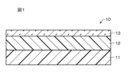
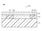
記録媒体10は、基材11と、基材11上に設けられた記録層12とを備える。記録媒体10は、記録層12上に設けられた保護層13をさらに備えていてもよい。以下、基材11、記録層12、保護層13について順次説明する。
The recording medium 10 includes a base material 11 and a recording layer 12 provided on the base material 11 . The recording medium 10 may further include a protective layer 13 provided on the recording layer 12 . The substrate 11, the recording layer 12, and the protective layer 13 will be described in order below.
(基材)
基材11は、記録層12を支持するための支持体である。基材11は、耐熱性に優れ、且つ、平面方向の寸法安定性に優れた材料により構成されていることが好ましい。基材11は、光透過性および非光透過性のどちらの特性を有していてもよい。基材11は、白色等の所定の色を有していてもよい。基材11は、例えば、板状またはフィルム状を有する。本開示においては、フィルムには、シートも含まれるものと定義する。 (Base material)
Thebase material 11 is a support for supporting the recording layer 12 . The base material 11 is preferably made of a material having excellent heat resistance and excellent dimensional stability in the planar direction. The substrate 11 may have either light transmissive or non-light transmissive properties. The base material 11 may have a predetermined color such as white. The substrate 11 has, for example, a plate shape or a film shape. In the present disclosure, film is defined to include sheet.
基材11は、記録層12を支持するための支持体である。基材11は、耐熱性に優れ、且つ、平面方向の寸法安定性に優れた材料により構成されていることが好ましい。基材11は、光透過性および非光透過性のどちらの特性を有していてもよい。基材11は、白色等の所定の色を有していてもよい。基材11は、例えば、板状またはフィルム状を有する。本開示においては、フィルムには、シートも含まれるものと定義する。 (Base material)
The
基材11は、例えば、剛性を有していてもよいし、可撓性を有していてもよい。基材11として可撓性を有するものが用いられた場合には、フレキシブルな記録媒体10を実現することができる。剛性を有する基材11としては、例えば、ウェハまたはガラス基板等が挙げられる。可撓性を有する基材11としては、例えば、フレキシブルガラス、フィルムまたは紙等が挙げられる。
The base material 11 may have rigidity or flexibility, for example. When a material having flexibility is used as the base material 11, a flexible recording medium 10 can be realized. Examples of the rigid base material 11 include a wafer and a glass substrate. Examples of the flexible substrate 11 include flexible glass, film, and paper.
基材11の構成材料としては、例えば、無機材料、金属材料または高分子材料等が挙げられる。これらの無機材料、金属材料および高分子材料等は、2種以上組み合わされてもよい。2種以上の構成材料が組み合わされる場合、2種以上の構成材料は積層されていてもよい。無機材料と高分子材料が組み合わされる場合、高分子フィルムに無機材料の粒子が分散され含まれていてもよい。同様に、金属材料と高分子材料が組み合わされる場合にも、高分子フィルムに金属材料の粒子が分散され含まれていてもよい。
Examples of constituent materials of the base material 11 include inorganic materials, metal materials, and polymer materials. Two or more of these inorganic materials, metal materials, polymer materials, and the like may be combined. When two or more constituent materials are combined, the two or more constituent materials may be laminated. When an inorganic material and a polymeric material are combined, the polymeric film may contain dispersed particles of the inorganic material. Similarly, when a metallic material and a polymeric material are combined, particles of the metallic material may be dispersed and included in the polymeric film.
無機材料は、例えば、ケイ素(Si)、酸化ケイ素(SiOX)、窒化ケイ素(SiNX)および酸化アルミニウム(AlOX)等からなる群より選ばれた少なくとも1種を含む。酸化ケイ素は、例えば、ガラスおよびスピンオングラス(SOG)等からなる群より選ばれた少なくとも1種を含む。金属材料は、例えば、アルミニウム(Al)、ニッケル(Ni)およびステンレス等からなる群より選ばれた少なくとも1種を含む。高分子材料は、例えば、ポリカーボネート(PC)、ポリエチレンテレフタレート(PET)、ポリエチレンナフタレート(PEN)、ポリエチルエーテルケトン(PEEK)およびポリ塩化ビニル(PVC)等からなる群より選ばれた少なくとも1種を含む。
The inorganic material includes, for example, at least one selected from the group consisting of silicon (Si), silicon oxide ( SiOx ), silicon nitride ( SiNx ) and aluminum oxide ( AlOx ). Silicon oxide includes, for example, at least one selected from the group consisting of glass, spin-on-glass (SOG), and the like. The metal material includes, for example, at least one selected from the group consisting of aluminum (Al), nickel (Ni), stainless steel, and the like. The polymeric material is, for example, at least one selected from the group consisting of polycarbonate (PC), polyethylene terephthalate (PET), polyethylene naphthalate (PEN), polyethyletherketone (PEEK), polyvinyl chloride (PVC), and the like. include.
なお、基材11の少なくとも一方の主面には、反射層(図示せず)が設けられていてもよいし、基材11自体が反射層としての機能を兼ね備えていてもよい。基材11がこのような構成を有していることで、より鮮明な色表示が可能となる。
A reflective layer (not shown) may be provided on at least one main surface of the substrate 11, or the substrate 11 itself may also function as a reflective layer. Since the base material 11 has such a structure, more vivid color display is possible.
(記録層)
未記録状態(初期状態)の記録層12は、消色状態にある。記録層12は、レーザー光の照射により消色状態から発色状態に変化することが可能である。記録層12は、発色状態において所定の色を呈することが可能である。所定の色としては、例えば、ブラック、シアン、マゼンタ、イエロー、レッド、グリーンまたはブルーが挙げられるが、これらの色に限定されるものではない。 (Recording layer)
Therecording layer 12 in an unrecorded state (initial state) is in an erased state. The recording layer 12 can change from a decolored state to a colored state by irradiation with a laser beam. The recording layer 12 can exhibit a predetermined color in a colored state. Predetermined colors include, for example, black, cyan, magenta, yellow, red, green, or blue, but are not limited to these colors.
未記録状態(初期状態)の記録層12は、消色状態にある。記録層12は、レーザー光の照射により消色状態から発色状態に変化することが可能である。記録層12は、発色状態において所定の色を呈することが可能である。所定の色としては、例えば、ブラック、シアン、マゼンタ、イエロー、レッド、グリーンまたはブルーが挙げられるが、これらの色に限定されるものではない。 (Recording layer)
The
記録層12の厚みは、好ましくは1μm以上20μm以下、より好ましくは2μm以上15μm以下である。記録層12の厚みが1μm以上であると、十分な発色濃度を得ることができる。一方、記録層12の厚みが20μm以下であると、記録層12の熱利用量が大きくなり過ぎることを抑制することができる。したがって、発色性が劣化することを抑制することができる。
The thickness of the recording layer 12 is preferably 1 μm or more and 20 μm or less, more preferably 2 μm or more and 15 μm or less. When the thickness of the recording layer 12 is 1 μm or more, sufficient color density can be obtained. On the other hand, when the thickness of the recording layer 12 is 20 μm or less, it is possible to prevent the heat utilization amount of the recording layer 12 from becoming too large. Therefore, it is possible to suppress the deterioration of color developability.
記録層12は、電子供与性を有する呈色性化合物と、電子受容性を有する顕色剤とを含む。記録層12は、光熱変換剤およびマトリックス樹脂からなる群より選ばれた少なくとも1種をさらに含むことが好ましい。
The recording layer 12 contains an electron-donating color former and an electron-accepting developer. The recording layer 12 preferably further contains at least one selected from the group consisting of photothermal conversion agents and matrix resins.
(呈色性化合物)
呈色性化合物は、顕色剤と反応することで発色することが可能である。呈色性化合物は、例えば、ロイコ色素である。ロイコ色素は、分子内に有するラクトン環が酸等の電子受容性化合物と反応すると、ラクトン環が開環状態となり発色する。ロイコ色素は、開環状態のラクトン環が塩基と反応すると、閉環状態となり消色してもよい。ロイコ色素は、例えば、既存の感熱紙用染料であってもよい。ロイコ色素は、例えば、既存の感熱紙用染料であってもよい。ロイコ色素の具体例としては、下記の式(2)で表される、分子内に電子供与性を有する基を含む化合物が挙げられる。 (Color-forming compound)
The color former can develop color by reacting with a developer. A color former is, for example, a leuco dye. A leuco dye develops a color when a lactone ring in the molecule reacts with an electron-accepting compound such as an acid to open the lactone ring. When the lactone ring in the open state reacts with a base, the leuco dye may be closed and decolored. Leuco dyes can be, for example, existing thermal paper dyes. Leuco dyes can be, for example, existing thermal paper dyes. A specific example of the leuco dye is a compound containing an electron-donating group in the molecule represented by the following formula (2).

呈色性化合物は、特に制限はなく、目的に応じて適宜選択することができる。具体的な呈色性化合物としては、例えば、フルオラン系化合物、トリフェニルメタンフタリド系化合物、アザフタリド系化合物、フェノチアジン系化合物、ロイコオーラミン系化合物およびインドリノフタリド系化合物等が挙げられる。この他、例えば、2-アニリノ-3-メチル-6-ジエチルアミノフルオラン、2-アニリノ-3-メチル-6-ジ(n-ブチルアミノ)フルオラン、2-アニリノ-3-メチル-6-(N-n-プロピル-N-メチルアミノ)フルオラン、2-アニリノ-3-メチル-6-(N-イソプロピル-N-メチルアミノ)フルオラン、2-アニリノ-3-メチル-6-(N-イソブチル-N-メチルアミノ)フルオラン、2-アニリノ-3-メチル-6-(N-n-アミル-N-メチルアミノ)フルオラン、2-アニリノ-3-メチル-6-(N-sec-ブチル-N-メチルアミノ)フルオラン、2-アニリノ-3-メチル-6-(N-n-アミル-N-エチルアミノ)フルオラン、2-アニリノ-3-メチル-6-(N-iso-アミル-N-エチルアミノ)フルオラン、2-アニリノ-3-メチル-6-(N-n-プロピル-N-イソプロピルアミノ)フルオラン、2-アニリノ-3-メチル-6-(N-シクロヘキシル-N-メチルアミノ)フルオラン、2-アニリノ-3-メチル-6-(N-エチル-p-トルイジノ)フルオラン、2-アニリノ-3-メチル-6-(N-メチル-p-トルイジノ)フルオラン、2-(m-トリクロロメチルアニリノ)-3-メチル-6-ジエチルアミノフルオラン、2-(m-トリフルロロメチルアニリノ)-3-メチル-6-ジエチルアミノフルオラン、2-(m-トリクロロメチルアニリノ)-3-メチル-6-(N-シクロヘキシル-N-メチルアミノ)フルオラン、2-(2,4-ジメチルアニリノ)-3-メチル-6-ジエチルアミノフルオラン、2-(N-エチル-p-トルイジノ)-3-メチル-6-(N-エチルアニリノ)フルオラン、2-(N-エチル-p-トルイジノ)-3-メチル-6-(N-プロピル-p-トルイジノ)フルオラン、2-アニリノ-6-(N-n-ヘキシル-N-エチルアミノ)フルオラン、2-(o-クロロアニリノ)-6-ジエチルアミノフルオラン、2-(o-クロロアニリノ)-6-ジブチルアミノフルオラン、2-(m-トリフロロメチルアニリノ)-6-ジエチルアミノフルオラン、2,3-ジメチル-6-ジメチルアミノフルオラン、3-メチル-6-(N-エチル-p-トルイジノ)フルオラン、2-クロロ-6-ジエチルアミノフルオラン、2-ブロモ-6-ジエチルアミノフルオラン、2-クロロ-6-ジプロピルアミノフルオラン、3-クロロ-6-シクロヘキシルアミノフルオラン、3-ブロモ-6-シクロヘキシルアミノフルオラン、2-クロロ-6-(N-エチル-N-イソアミルアミノ)フルオラン、2-クロロ-3-メチル-6-ジエチルアミノフルオラン、2-アニリノ-3-クロロ-6-ジエチルアミノフルオラン、2-(o-クロロアニリノ)-3-クロロ-6-シクロヘキシルアミノフルオラン、2-(m-トリフロロメチルアニリノ)-3-クロロ-6-ジエチルアミノフルオラン、2-(2,3-ジクロロアニリノ)-3-クロロ-6-ジエチルアミノフルオラン、1,2-ベンゾ-6-ジエチルアミノフルオラン、3-ジエチルアミノ-6-(m-トリフロロメチルアニリノ)フルオラン、3-(1-エチル-2-メチルインドール-3-イル)-3-(2-エトキシ-4-ジエチルアミノフェニル)-4-アザフタリド、3-(1-エチル-2-メチルインドール-3-イル)-3-(2-エトキシ-4-ジエチルアミノフェニル)-7-アザフタリド、3-(1-オクチル-2-メチルインドール-3-イル)-3-(2-エトキシ-4-ジエチルアミノフェニル)-4-アザフタリド、3-(1-エチル-2-メチルインドール-3-イル)-3-(2-メチル-4-ジエチルアミノフェニル)-4-アザフタリド、3-(1-エチル-2-メチルインドール-3-イル)-3-(2-メチル-4-ジエチルアミノフェニル)-7-アザフタリド、3-(1-エチル-2-メチルインドール-3-イル)-3-(4-ジエチルアミノフェニル)-4-アザフタリド、3-(1-エチル-2-メチルインドール-3-イル)-3-(4-N-n-アミル-N-メチルアミノフェニル)-4-アザフタリド、3-(1-メチル-2-メチルインドール-3-イル)-3-(2-ヘキシルオキシ-4-ジエチルアミノフェニル)-4-アザフタリド、3,3-ビス(2-エトキシ-4-ジエチルアミノフェニル)-4-アザフタリド、3,3-ビス(2-エトキシ-4-ジエチルアミノフェニル)-7-アザフタリド、2-(p-アセチルアニリノ)-6-(N-n-アミル-N-n-ブチルアミノ)フルオラン、2-ベンジルアミノ-6-(N-エチル-p-トルイジノ)フルオラン、2-ベンジルアミノ-6-(N-メチル-2,4-ジメチルアニリノ)フルオラン、2-ベンジルアミノ-6-(N-エチル-2,4-ジメチルアニリノ)フルオラン、2-ベンジルアミノ-6-(N-メチル-p-トルイジノ)フルオラン、2-ベンジルアミノ-6-(N-エチル-p-トルイジノ)フルオラン、2-(ジ-p-メチルベンジルアミノ)-6-(N-エチル-p-トルイジノ)フルオラン、2-(α-フェニルエチルアミノ)-6-(N-エチル-p-トルイジノ)フルオラン、2-メチルアミノ-6-(N-メチルアニリノ)フルオラン、2-メチルアミノ-6-(N-エチルアニリノ)フルオラン、2-メチルアミノ-6-(N-プロピルアニリノ)フルオラン、2-エチルアミノ-6-(N-メチル-p-トルイジノ)フルオラン、2-メチルアミノ-6-(N-メチル-2,4-ジメチルアニリノ)フルオラン、2-エチルアミノ-6-(N-エチル-2,4-ジメチルアニリノ)フルオラン、2-ジメチルアミノ-6-(N-メチルアニリノ)フルオラン、2-ジメチルアミノ-6-(N-エチルアニリノ)フルオラン、2-ジエチルアミノ-6-(N-メチル-p-トルイジノ)フルオラン、2-ジエチルアミノ-6-(N-エチル-p-トルイジノ)フルオラン、2-ジプロピルアミノ-6-(N-メチルアニリノ)フルオラン、2-ジプロピルアミノ-6-(N-エチルアニリノ)フルオラン、2-アミノ-6-(N-メチルアニリノ)フルオラン、2-アミノ-6-(N-エチルアニリノ)フルオラン、2-アミノ-6-(N-プロピルアニリノ)フルオラン、2-アミノ-6-(N-メチル-p-トルイジノ)フルオラン、2-アミノ-6-(N-エチル-p-トルイジノ)フルオラン、2-アミノ-6-(N-プロピル-p-トルイジノ)フルオラン、2-アミノ-6-(N-メチル-p-エチルアニリノ)フルオラン、2-アミノ-6-(N-エチル-p-エチルアニリノ)フルオラン、2-アミノ-6-(N-プロピル-p-エチルアニリノ)フルオラン、2-アミノ-6-(N-メチル-2,4-ジメチルアニリノ)フルオラン、2-アミノ-6-(N-エチル-2,4-ジメチルアニリノ)フルオラン、2-アミノ-6-(N-プロピル-2,4-ジメチルアニリノ)フルオラン、2-アミノ-6-(N-メチル-p-クロロアニリノ)フルオラン、2-アミノ-6-(N-エチル-p-クロロアニリノ)フルオラン、2-アミノ-6-(N-プロピル-p-クロロアニリノ)フルオラン、1,2-ベンゾ-6-(N-エチル-N-イソアミルアミノ)フルオラン、1,2-ベンゾ-6-ジブチルアミノフルオラン、1,2-ベンゾ-6-(N-メチル-N-シクロヘキシルアミノ)フルオランおよび1,2-ベンゾ-6-(N-エチル-N-トルイジノ)フルオラン等が挙げられる。記録層12はそれぞれ、上記ロイコ色素のうちの1種を単独で含んでいてもよいし、2種以上を含んでもよい。
The color-forming compound is not particularly limited and can be appropriately selected according to the purpose. Specific color compounds include, for example, fluoran-based compounds, triphenylmethanephthalide-based compounds, azaphthalide-based compounds, phenothiazine-based compounds, leuco auramine-based compounds, and indolinophthalide-based compounds. In addition, for example, 2-anilino-3-methyl-6-diethylaminofluorane, 2-anilino-3-methyl-6-di(n-butylamino)fluorane, 2-anilino-3-methyl-6-(N -n-propyl-N-methylamino)fluorane, 2-anilino-3-methyl-6-(N-isopropyl-N-methylamino)fluorane, 2-anilino-3-methyl-6-(N-isobutyl-N -methylamino)fluorane, 2-anilino-3-methyl-6-(Nn-amyl-N-methylamino)fluorane, 2-anilino-3-methyl-6-(N-sec-butyl-N-methyl amino) fluorane, 2-anilino-3-methyl-6-(Nn-amyl-N-ethylamino) fluorane, 2-anilino-3-methyl-6-(N-iso-amyl-N-ethylamino) Fluorane, 2-anilino-3-methyl-6-(Nn-propyl-N-isopropylamino)fluorane, 2-anilino-3-methyl-6-(N-cyclohexyl-N-methylamino)fluorane, 2- Anilino-3-methyl-6-(N-ethyl-p-toluidino)fluorane, 2-anilino-3-methyl-6-(N-methyl-p-toluidino)fluorane, 2-(m-trichloromethylanilino) -3-methyl-6-diethylaminofluorane, 2-(m-trifluoromethylanilino)-3-methyl-6-diethylaminofluorane, 2-(m-trichloromethylanilino)-3-methyl-6- (N-cyclohexyl-N-methylamino)fluorane, 2-(2,4-dimethylanilino)-3-methyl-6-diethylaminofluorane, 2-(N-ethyl-p-toluidino)-3-methyl- 6-(N-ethylanilino)fluorane, 2-(N-ethyl-p-toluidino)-3-methyl-6-(N-propyl-p-toluidino)fluorane, 2-anilino-6-(Nn-hexyl -N-ethylamino)fluorane, 2-(o-chloroanilino)-6-diethylaminofluorane, 2-(o-chloroanilino)-6-dibutylaminofluorane, 2-(m-trifluoromethylanilino)-6 -diethylaminofluorane, 2,3-dimethyl-6-dimethylaminofluorane, 3-methyl-6-(N-ethyl-p-toluidino)fluorane, 2-chloro-6-diethylaminofluorane, 2-bromo-6 -diethylaminofluorane, 2-chloro-6-dipropyl Aminofluorane, 3-chloro-6-cyclohexylaminofluorane, 3-bromo-6-cyclohexylaminofluorane, 2-chloro-6-(N-ethyl-N-isoamylamino)fluorane, 2-chloro-3- methyl-6-diethylaminofluorane, 2-anilino-3-chloro-6-diethylaminofluorane, 2-(o-chloroanilino)-3-chloro-6-cyclohexylaminofluorane, 2-(m-trifluoromethylani Lino)-3-chloro-6-diethylaminofluorane, 2-(2,3-dichloroanilino)-3-chloro-6-diethylaminofluorane, 1,2-benzo-6-diethylaminofluorane, 3-diethylamino -6-(m-trifluoromethylanilino)fluorane, 3-(1-ethyl-2-methylindol-3-yl)-3-(2-ethoxy-4-diethylaminophenyl)-4-azaphthalide, 3- (1-ethyl-2-methylindol-3-yl)-3-(2-ethoxy-4-diethylaminophenyl)-7-azaphthalide, 3-(1-octyl-2-methylindol-3-yl)-3 -(2-ethoxy-4-diethylaminophenyl)-4-azaphthalide, 3-(1-ethyl-2-methylindol-3-yl)-3-(2-methyl-4-diethylaminophenyl)-4-azaphthalide, 3-(1-ethyl-2-methylindol-3-yl)-3-(2-methyl-4-diethylaminophenyl)-7-azaphthalide, 3-(1-ethyl-2-methylindol-3-yl) -3-(4-diethylaminophenyl)-4-azaphthalide, 3-(1-ethyl-2-methylindol-3-yl)-3-(4-Nn-amyl-N-methylaminophenyl)-4 -azaphthalide, 3-(1-methyl-2-methylindol-3-yl)-3-(2-hexyloxy-4-diethylaminophenyl)-4-azaphthalide, 3,3-bis(2-ethoxy-4- diethylaminophenyl)-4-azaphthalide, 3,3-bis(2-ethoxy-4-diethylaminophenyl)-7-azaphthalide, 2-(p-acetylanilino)-6-(Nn-amyl-Nn -butylamino)fluorane, 2-benzylamino-6-(N-ethyl-p-toluidino)fluorane, 2-benzylamino-6-(N-methyl-2,4-dimethylanilino)fluorane, 2-benzylamino -6-(N-E ethyl-2,4-dimethylanilino)fluorane, 2-benzylamino-6-(N-methyl-p-toluidino)fluorane, 2-benzylamino-6-(N-ethyl-p-toluidino)fluorane, 2- (Di-p-methylbenzylamino)-6-(N-ethyl-p-toluidino)fluorane, 2-(α-phenylethylamino)-6-(N-ethyl-p-toluidino)fluorane, 2-methylamino -6-(N-methylanilino)fluorane, 2-methylamino-6-(N-ethylanilino)fluorane, 2-methylamino-6-(N-propylanilino)fluorane, 2-ethylamino-6-(N- methyl-p-toluidino)fluorane, 2-methylamino-6-(N-methyl-2,4-dimethylanilino)fluorane, 2-ethylamino-6-(N-ethyl-2,4-dimethylanilino) Fluorane, 2-dimethylamino-6-(N-methylanilino)fluorane, 2-dimethylamino-6-(N-ethylanilino)fluorane, 2-diethylamino-6-(N-methyl-p-toluidino)fluorane, 2-diethylamino -6-(N-ethyl-p-toluidino)fluorane, 2-dipropylamino-6-(N-methylanilino)fluorane, 2-dipropylamino-6-(N-ethylanilino)fluorane, 2-amino-6- (N-methylanilino)fluorane, 2-amino-6-(N-ethylanilino)fluorane, 2-amino-6-(N-propylanilino)fluorane, 2-amino-6-(N-methyl-p-toluidino) Fluorane, 2-amino-6-(N-ethyl-p-toluidino)fluorane, 2-amino-6-(N-propyl-p-toluidino)fluorane, 2-amino-6-(N-methyl-p-ethylanilino ) fluoran, 2-amino-6-(N-ethyl-p-ethylanilino)fluorane, 2-amino-6-(N-propyl-p-ethylanilino)fluorane, 2-amino-6-(N-methyl-2, 4-dimethylanilino)fluorane, 2-amino-6-(N-ethyl-2,4-dimethylanilino)fluorane, 2-amino-6-(N-propyl-2,4-dimethylanilino)fluorane, 2-amino-6-(N-methyl-p-chloroanilino)fluorane, 2-amino-6-(N-ethyl-p-chloroanilino)fluorane, 2-amino-6-(N-propyl-p-chloroanilino)fluorane , 1,2-benzo-6-(N-ethyl-N-isoamylamino)fluorane, 1,2-benzo-6-dibutylaminofluorane, 1,2-benzo-6-(N-methyl-N-cyclohexylamino ) fluorane and 1,2-benzo-6-(N-ethyl-N-toluidino)fluorane. Each of the recording layers 12 may contain one of the above leuco dyes alone, or may contain two or more of them.
(顕色剤)
顕色剤は、例えば、無色の呈色性化合物を発色させることができる。顕色剤は、分子内に電子受容性を有する基を含む化合物である。顕色剤の電子受容性部が呈色性化合物のラクトン環と反応し、ラクトン環が開環することで、呈色性化合物が発色する。 (developer)
The color developer can, for example, develop a colorless color former. A developer is a compound containing an electron-accepting group in the molecule. The electron-accepting moiety of the color developer reacts with the lactone ring of the color former, and the lactone ring is opened, whereby the color former develops color.
顕色剤は、下記の式(a)で表される化合物を含む。

(但し、式(a)中、X0は、少なくとも1つのベンゼン環を含む二価の基である。Y01、Y02はそれぞれ独立して、一価の基である。n01、n02はそれぞれ独立して、0から5のいずれかの整数である。n01が2から5のいずれかの整数である場合、Y01は互いに同一であってもよいし、異なっていてもよい。n02が2から5のいずれかの整数である場合、Y02は互いに同一であってもよいし、異なっていてもよい。Z01、Z02はそれぞれ独立して、水素結合性基である。)
The developer includes a compound represented by formula (a) below.
(In formula (a), X 0 is a divalent group containing at least one benzene ring. Y 01 and Y 02 are each independently monovalent groups. n01 and n02 are each independently an integer of 0 to 5. When n01 is an integer of 2 to 5, Y 01 may be the same or different, n02 is 2 When it is any integer from to 5, Y 02 may be the same or different, and Z 01 and Z 02 are each independently a hydrogen bonding group.)
X0が少なくとも1つのベンゼン環を含むことで、X0が脂肪族炭化水素基(例えばノルマルアルキル鎖)である場合に比べて融点を高くすることができるので、高温高湿保管時の発色保持特性(以下「高温高湿保管特性」という。)を向上させることができる。高温高湿保管特性および耐熱性の向上の観点から、X0が、少なくとも2つのベンゼン環を含むことが好ましい。高温高湿保管特性は、例えば、80℃、60%RHの環境下における保管特性である。耐熱性が向上されると、過酷なプロセス(例えば、加熱プレスまたは溶融樹脂等を用いた一体成型等)に対する記録媒体10の耐性が向上される。X0が少なくとも2つのベンゼン環を含む場合、少なくとも2つのベンゼン環が縮合していてもよい。例えば、ナフタレンまたはアントラセン等であってもよい。
When X 0 contains at least one benzene ring, the melting point can be made higher than when X 0 is an aliphatic hydrocarbon group (for example, normal alkyl chain). Characteristics (hereinafter referred to as "high temperature and high humidity storage characteristics") can be improved. From the viewpoint of improving high-temperature, high-humidity storage properties and heat resistance, X 0 preferably contains at least two benzene rings. High-temperature and high-humidity storage properties are, for example, storage properties in an environment of 80° C. and 60% RH. When the heat resistance is improved, the resistance of the recording medium 10 to severe processes (for example, heat pressing, integral molding using molten resin, etc.) is improved. When X 0 contains at least two benzene rings, the at least two benzene rings may be fused. For example, it may be naphthalene or anthracene.
Z01、Z02がそれぞれ独立して水素結合性基であることで、顕色剤同士が水素結合を介してある程度固まって存在しやすいため、記録層12内における顕色剤の安定性が向上する。本明細書において、水素結合性基は、他の官能基または他の化合物等に存在する原子と水素結合することができる原子を含む官能基を意味する。
When Z 01 and Z 02 are each independently hydrogen-bonding groups, the color developer tends to exist in a certain degree of solidification through hydrogen bonding, so the stability of the color developer in the recording layer 12 is improved. do. As used herein, a hydrogen-bonding group means a functional group containing atoms capable of hydrogen bonding with atoms present in other functional groups or other compounds.
顕色剤は、下記の式(1)で表される化合物を含むことが好ましい。

(但し、式(1)中、X1は、少なくとも1つのベンゼン環を含む二価の基である。Y11、Y12、Y13、Y14はそれぞれ独立して、一価の基である。Z11、Z12はそれぞれ独立して、水素結合性基である。)
The developer preferably contains a compound represented by the following formula (1).
(In formula (1), X 1 is a divalent group containing at least one benzene ring. Y 11 , Y 12 , Y 13 and Y 14 are each independently a monovalent group. (Z 11 and Z 12 are each independently a hydrogen-bonding group.)
X1が少なくとも1つのベンゼン環を含むことで、X1が脂肪族炭化水素基(例えばノルマルアルキル鎖)である場合に比べて融点を高くすることができるので、高温高湿保管特性を向上させることができる。高温高湿保管特性および耐熱性の向上の観点から、X1が、少なくとも2つのベンゼン環を含むことが好ましい。X1が少なくとも2つのベンゼン環を含む場合、少なくとも2つのベンゼン環が縮合していてもよい。例えば、ナフタレンまたはアントラセン等であってもよい。
When X 1 contains at least one benzene ring, the melting point can be made higher than when X 1 is an aliphatic hydrocarbon group (for example, a normal alkyl chain), thereby improving high-temperature and high-humidity storage properties. be able to. From the viewpoint of improving high-temperature, high-humidity storage properties and heat resistance, X 1 preferably contains at least two benzene rings. When X 1 contains at least two benzene rings, at least two benzene rings may be fused. For example, it may be naphthalene or anthracene.
Z11、Z12がそれぞれ独立して水素結合性基であることで、顕色剤同士が水素結合を介してある程度固まって存在しやすいため、記録層12内における顕色剤の安定性が向上する。
When Z 11 and Z 12 are each independently hydrogen-bonding groups, the color developer tends to exist in a state of solidification to some extent through hydrogen bonding, so the stability of the color developer in the recording layer 12 is improved. do.
式(a)および式(1)が炭化水素基を含む場合、当該炭化水素基は、炭素(C)および水素(H)により構成される基の総称であり、飽和炭化水素基であってもよいし、不飽和炭化水素基であってもよい。飽和炭化水素基は、炭素間多重結合を有しない脂肪族炭化水素基であり、不飽和炭化水素基は、炭素間多重結合(炭素間二重結合または炭素間三重結合)を有する脂肪族炭化水素基である。
When the formula (a) and the formula (1) contain a hydrocarbon group, the hydrocarbon group is a general term for groups composed of carbon (C) and hydrogen (H), even if it is a saturated hydrocarbon group. Alternatively, it may be an unsaturated hydrocarbon group. A saturated hydrocarbon group is an aliphatic hydrocarbon group having no carbon-carbon multiple bonds, and an unsaturated hydrocarbon group is an aliphatic hydrocarbon group having a carbon-carbon multiple bond (a carbon-carbon double bond or a carbon-carbon triple bond). is the base.
式(a)および式(1)が炭化水素基を含む場合、当該炭化水素基は、鎖状であってもよいし、1個または2個以上の環を含んでもよい。鎖状は、直鎖状であってもよいし、1または2以上の側鎖等を有する分岐状でもよい。
When Formula (a) and Formula (1) contain a hydrocarbon group, the hydrocarbon group may be chain-shaped or may contain one or more rings. The chain may be linear or branched having one or more side chains or the like.
(1つのベンゼン環を含むX0、X1)
式(a)中のX0および式(1)中のX1は、例えば、1つのベンゼン環を含む二価の基である。当該二価の基は、例えば、下記の式(3)で表される。

(但し、式(3)中、X21はあってもなくてもよく、X21がある場合、X21は二価の基である。X22はあってもなくてもよく、X22がある場合、X22は二価の基である。R21は、一価の基である。n21は、0から4のいずれかの整数である。n21が2から4のいずれかの整数である場合、R21は互いに同一であってもよいし、異なっていてもよい。*印は結合部を表す。)
(X 0 , X 1 containing one benzene ring)
X 0 in formula (a) and X 1 in formula (1) are, for example, divalent groups containing one benzene ring. The divalent group is represented, for example, by the following formula (3).
(In formula (3), X 21 may or may not be present, and when X 21 is present, X 21 is a divalent group. X 22 may or may not be present, and X 22 is In some cases, X 22 is a divalent group R 21 is a monovalent group n21 is an integer from 0 to 4 n21 is an integer from 2 to 4 , R 21 may be the same or different from each other.* indicates a bond.)
式(a)中のX0および式(1)中のX1は、例えば、1つのベンゼン環を含む二価の基である。当該二価の基は、例えば、下記の式(3)で表される。
X 0 in formula (a) and X 1 in formula (1) are, for example, divalent groups containing one benzene ring. The divalent group is represented, for example, by the following formula (3).
式(3)において、ベンゼン環に対するX21およびX22の結合位置は限定されない。すなわち、ベンゼン環に対するX21およびX22の結合位置は、オルト位、メタ位およびパラ位のいずれであってもよい。
In formula (3), the bonding positions of X 21 and X 22 to the benzene ring are not limited. That is, the bonding position of X 21 and X 22 to the benzene ring may be any of the ortho-, meta- and para-positions.
1つのベンゼン環を含む上記二価の基は、高温高湿保管特性の向上の観点から、下記の式(4)で表されることが好ましい。

(但し、式(4)中、R22は、一価の基である。n22は、0から4のいずれかの整数である。n22が2から4のいずれかの整数である場合、R22は互いに同一であってもよいし、異なっていてもよい。*印は結合部を表す。)
The divalent group containing one benzene ring is preferably represented by the following formula (4) from the viewpoint of improving high-temperature and high-humidity storage properties.
(In formula (4), R 22 is a monovalent group. n22 is an integer of 0 to 4. When n22 is an integer of 2 to 4, R 22 may be the same as or different from each other.* indicates a joint.)
式(a)中のX0が1つのベンゼン環を含む二価の基である場合、式(4)において、ベンゼン環に対するZ01およびZ02の結合位置は限定されない。すなわち、ベンゼン環に対するZ01およびZ02の結合位置は、オルト位、メタ位およびパラ位のいずれであってもよい。
When X 0 in formula (a) is a divalent group containing one benzene ring, in formula (4), the bonding positions of Z 01 and Z 02 with respect to the benzene ring are not limited. That is, the bonding positions of Z 01 and Z 02 with respect to the benzene ring may be any of ortho, meta and para positions.
式(1)中のX1が1つのベンゼン環を含む二価の基である場合、式(4)において、ベンゼン環に対するZ11およびZ12の結合位置は限定されない。すなわち、ベンゼン環に対するZ11およびZ12の結合位置は、オルト位、メタ位およびパラ位のいずれであってもよい。
When X 1 in formula (1) is a divalent group containing one benzene ring, the bonding positions of Z 11 and Z 12 with respect to the benzene ring are not limited in formula (4). That is, the bonding positions of Z 11 and Z 12 with respect to the benzene ring may be any of ortho, meta and para positions.
(X21、X22)
式(3)中のX21、X22はそれぞれ独立して、二価の基であればよく、特に限定されるものではないが、例示するならば、置換基を有していてもよい炭化水素基である。炭化水素基は、鎖状であることが好ましい。炭化水素基が鎖状であると、顕色剤の融点を低減することができるので、レーザー光の照射により顕色剤が溶けて、呈色性化合物を発色させ易くなる。顕色剤の融点の低減の観点からすると、鎖状の炭化水素基のうちのでも、ノルマルアルキル鎖が特に好ましい。 ( X21 , X22 )
X 21 and X 22 in formula (3) are each independently a divalent group and are not particularly limited. It is a hydrogen group. The hydrocarbon group is preferably chain-like. If the hydrocarbon group is chain-like, the melting point of the color developer can be lowered, so that the color developer melts upon irradiation with a laser beam, making it easier for the color former to develop color. From the viewpoint of reducing the melting point of the color developer, a normal alkyl chain is particularly preferred among chain hydrocarbon groups.
置換基を有していてもよい炭化水素基の炭素数は、例えば、1以上15以下、1以上13以下、1以上12以下、1以上10以下、1以上6以下または1以上3以下である。
The number of carbon atoms in the optionally substituted hydrocarbon group is, for example, 1 to 15, 1 to 13, 1 to 12, 1 to 10, 1 to 6, or 1 to 3. .
式(3)中のX21、X22がノルマルアルキル基である場合、当該ノルマルアルキル基の炭素数は、高温保管安定性の観点から、好ましくは8以下、より好ましくは6以下、さらにより好ましくは5以下、特に好ましくは3以下である。ノルマルアルキル基の炭素数が8以下であると、ノルマルアルキル基の長さ短いため、高温保管時に熱的な乱れが顕色剤に生じ難く、発色時にロイコ色素等の呈色性化合物と相互作用していた部位が外れ難くなると考えられる。したがって、高温保管時にロイコ色素等の呈色性化合物が消色し難くなるため、高温保管安定性が向上する。
When X 21 and X 22 in formula (3) are normal alkyl groups, the number of carbon atoms in the normal alkyl group is preferably 8 or less, more preferably 6 or less, and even more preferably 6 or less, from the viewpoint of high-temperature storage stability. is 5 or less, particularly preferably 3 or less. When the number of carbon atoms in the normal alkyl group is 8 or less, the length of the normal alkyl group is short, so that the color developer is less likely to be thermally disturbed during high-temperature storage, and interacts with a color former such as a leuco dye during color development. It is thought that it becomes difficult to remove the part that was attached. Therefore, the color-developing compound such as the leuco dye is less likely to decolor during high-temperature storage, thereby improving the high-temperature storage stability.
炭化水素基が有しいてもよい置換基としては、例えば、ハロゲン基(例えばフッ素基)またはハロゲン基(例えばフッ素基)を有するアルキル基等が挙げられる。置換基を有していてもよい炭化水素基は、炭化水素基の炭素の一部(例えば炭化水素基の主鎖に含まれる炭素の一部)が酸素等の元素で置換されたものでもよい。
Examples of the substituent that the hydrocarbon group may have include a halogen group (eg, fluorine group) or an alkyl group having a halogen group (eg, fluorine group). The hydrocarbon group which may have a substituent may be one in which part of the carbon atoms of the hydrocarbon group (for example, part of the carbon atoms contained in the main chain of the hydrocarbon group) is substituted with an element such as oxygen. .
(R21)
式(3)中のR21は、一価の基であればよく、特に限定されるものではないが、例示するならば、ハロゲン基または置換基を有していてもよい炭化水素基である。 ( R21 )
R 21 in formula (3) is not particularly limited as long as it is a monovalent group, but for example, it is a halogen group or a hydrocarbon group which may have a substituent. .
式(3)中のR21は、一価の基であればよく、特に限定されるものではないが、例示するならば、ハロゲン基または置換基を有していてもよい炭化水素基である。 ( R21 )
R 21 in formula (3) is not particularly limited as long as it is a monovalent group, but for example, it is a halogen group or a hydrocarbon group which may have a substituent. .
ハロゲン基は、例えば、フッ素基(-F)、塩素基(-Cl)、臭素基(-Br)またはヨウ素基(-I)である。
A halogen group is, for example, a fluorine group (-F), a chlorine group (-Cl), a bromine group (-Br) or an iodine group (-I).
置換基を有していてもよい炭化水素基の炭素数は、例えば、1以上15以下、1以上13以下、1以上12以下、1以上10以下、1以上6以下または1以上3以下である。
The number of carbon atoms in the optionally substituted hydrocarbon group is, for example, 1 to 15, 1 to 13, 1 to 12, 1 to 10, 1 to 6, or 1 to 3. .
炭化水素基が有しいてもよい置換基としては、例えば、ハロゲン基(例えばフッ素基)またはハロゲン基(例えばフッ素基)を有するアルキル基等が挙げられる。置換基を有していてもよい炭化水素基は、炭化水素基の炭素の一部(例えば炭化水素基の主鎖に含まれる炭素の一部)が酸素等の元素で置換されたものでもよい。
Examples of the substituent that the hydrocarbon group may have include a halogen group (eg, fluorine group) or an alkyl group having a halogen group (eg, fluorine group). The hydrocarbon group which may have a substituent may be one in which part of the carbon atoms of the hydrocarbon group (for example, part of the carbon atoms contained in the main chain of the hydrocarbon group) is substituted with an element such as oxygen. .
(R22)
式(4)中のR22は、一価の基であればよく、特に限定されるものではないが、例示するならば、ハロゲン基または置換基を有していてもよい炭化水素基である。ハロゲン基、置換基を有していてもよい炭化水素基はそれぞれ、上記(3)式中のR21と同様である。 ( R22 )
R 22 in formula (4) is not particularly limited as long as it is a monovalent group, but for example, it is a halogen group or a hydrocarbon group which may have a substituent. . Halogen group and optionally substituted hydrocarbon group are the same as R 21 in formula (3) above.
(2つのベンゼン環を含むX0、X1)
式(a)中のX0および式(1)中のX1は、例えば、2つのベンゼン環を含む二価の基である。当該二価の基は、例えば、下記の式(5)で表される。

(但し、式(5)中、X31はあってもなくてもよく、X31がある場合、X31は二価の基である。X32はあってもなくてもよく、X32がある場合、X32は二価の基である。X33はあってもなくてもよく、X33がある場合、X33は二価の基である。R31、R32はそれぞれ独立して、一価の基である。n31、n32はそれぞれ独立して、0から4のいずれかの整数である。n31が2から4のいずれかの整数である場合、R31は互いに同一であってもよいし、異なっていてもよい。n32が2から4のいずれかの整数である場合、R32は互いに同一であってもよいし、異なっていてもよい。*印は結合部を表す。)
(X 0 , X 1 containing two benzene rings)
X 0 in formula (a) and X 1 in formula (1) are, for example, divalent groups containing two benzene rings. The divalent group is represented, for example, by the following formula (5).
(In formula (5), X 31 may or may not be present, and when X 31 is present, X 31 is a divalent group. X 32 may or may not be present, and X 32 is In some cases, X 32 is a divalent group.X 33 may or may not be present, and when X 33 is present, X 33 is a divalent group.R 31 and R 32 are each independently , a monovalent group, n31 and n32 are each independently an integer of 0 to 4. When n31 is an integer of 2 to 4, R 31 are the same When n32 is an integer of 2 to 4, R 32 may be the same or different, and * indicates a bond. )
式(a)中のX0および式(1)中のX1は、例えば、2つのベンゼン環を含む二価の基である。当該二価の基は、例えば、下記の式(5)で表される。
X 0 in formula (a) and X 1 in formula (1) are, for example, divalent groups containing two benzene rings. The divalent group is represented, for example, by the following formula (5).
式(5)において、ベンゼン環に対するX31およびX32の結合位置は限定されない。すなわち、ベンゼン環に対するX31およびX32の結合位置は、オルト位、メタ位およびパラ位のいずれであってもよい。同様に、式(5)において、ベンゼン環に対するX32およびX33の結合位置は限定されない。すなわち、ベンゼン環に対するX32およびX33の結合位置は、オルト位、メタ位およびパラ位のいずれであってもよい。
In formula (5), the binding positions of X 31 and X 32 to the benzene ring are not limited. That is, the bonding positions of X 31 and X 32 to the benzene ring may be any of ortho, meta and para positions. Similarly, in formula (5), the bonding positions of X 32 and X 33 to the benzene ring are not limited. That is, the bonding positions of X 32 and X 33 to the benzene ring may be any of ortho, meta and para positions.
2つのベンゼン環を含む上記二価の基は、高温高湿保管特性の向上の観点から、下記の式(6)で表されることが好ましい。

(但し、式(6)中、X34は、二価の基である。R33、R34はそれぞれ独立して、一価の基である。n33、n34はそれぞれ独立して、0から4のいずれかの整数である。n33が2から4のいずれかの整数である場合、R33は互いに同一であってもよいし、異なっていてもよい。n34が2から4のいずれかの整数である場合、R34は互いに同一であってもよいし、異なっていてもよい。*印は結合部を表す。)
The divalent group containing two benzene rings is preferably represented by the following formula (6) from the viewpoint of improving high-temperature and high-humidity storage properties.
(In formula (6), X 34 is a divalent group. R 33 and R 34 are each independently a monovalent group. n33 and n34 are each independently 0 to 4 When n33 is an integer of 2 to 4, R 33 may be the same or different, and n34 is an integer of 2 to 4 , R 34 may be the same or different from each other.* indicates a bond.)
式(a)中のX0が2つのベンゼン環を含む二価の基である場合、式(6)において、ベンゼン環に対するZ01およびX34の結合位置は限定されない。すなわち、ベンゼン環に対するZ01およびX34の結合位置は、オルト位、メタ位およびパラ位のいずれであってもよい。同様に、式(6)において、ベンゼン環に対するZ02およびX34の結合位置は限定されない。すなわち、ベンゼン環に対するZ02およびX34の結合位置は、オルト位、メタ位およびパラ位のいずれであってもよい。
When X 0 in formula (a) is a divalent group containing two benzene rings, the bonding positions of Z 01 and X 34 with respect to the benzene ring are not limited in formula (6). That is, the bonding positions of Z 01 and X 34 with respect to the benzene ring may be any of ortho, meta and para positions. Similarly, in formula (6), the binding positions of Z 02 and X 34 to the benzene ring are not limited. That is, the bonding positions of Z 02 and X 34 with respect to the benzene ring may be any of ortho, meta and para positions.
式(1)中のX1が2つのベンゼン環を含む二価の基である場合、式(6)において、ベンゼン環に対するZ11およびX34の結合位置は限定されない。すなわち、ベンゼン環に対するZ11およびX34の結合位置は、オルト位、メタ位およびパラ位のいずれであってもよい。同様に、式(6)において、ベンゼン環に対するZ12およびX34の結合位置は限定されない。すなわち、ベンゼン環に対するZ12およびX34の結合位置は、オルト位、メタ位およびパラ位のいずれであってもよい。
When X 1 in Formula (1) is a divalent group containing two benzene rings, in Formula (6), the bonding positions of Z 11 and X 34 to the benzene ring are not limited. That is, the bonding positions of Z 11 and X 34 with respect to the benzene ring may be any of ortho, meta and para positions. Similarly, in formula (6), the bonding positions of Z 12 and X 34 to the benzene ring are not limited. That is, the bonding positions of Z 12 and X 34 with respect to the benzene ring may be any of ortho, meta and para positions.
(X31、X32、X33)
式(5)中のX31、X32、X33はそれぞれ独立して、二価の基であればよく、特に限定されるものではないが、例示するならば、置換基を有していてもよい炭化水素基である。当該炭化水素基は、上記の式(3)中のX21、X22と同様である。 ( X31 , X32 , X33 )
X 31 , X 32 , and X 33 in formula (5) are each independently a divalent group, and are not particularly limited. is a good hydrocarbon group. The hydrocarbon group is the same as X 21 and X 22 in formula (3) above.
(X34)
式(6)中のX34は、二価の基であればよく、特に限定されるものではないが、例示するならば、置換基を有していてもよい炭化水素基である。当該炭化水素基は、上記の式(3)中のX21、X22と同様である。 ( X34 )
X 34 in formula (6) is not particularly limited as long as it is a divalent group, but for example, it is a hydrocarbon group which may have a substituent. The hydrocarbon group is the same as X 21 and X 22 in formula (3) above.
(R31、R32)
式(5)中のR31、R32は、一価の基であればよく、特に限定されるものではないが、例示するならば、ハロゲン基または置換基を有していてもよい炭化水素基である。ハロゲン基、置換基を有していてもよい炭化水素基はそれぞれ、上記の式(3)中のR21と同様である。 ( R31 , R32 )
R 31 and R 32 in formula (5) are not particularly limited as long as they are monovalent groups, but for example, a halogen group or an optionally substituted hydrocarbon is the base. The halogen group and the optionally substituted hydrocarbon group are the same as R 21 in the above formula (3).
(R33、R34)
式(6)中のR33、R34は、一価の基であればよく、特に限定されるものではないが、例示するならば、ハロゲン基または置換基を有していてもよい炭化水素基である。ハロゲン基、置換基を有していてもよい炭化水素基はそれぞれ、上記の式(3)中のR21と同様である。 ( R33 , R34 )
R 33 and R 34 in formula (6) are not particularly limited as long as they are monovalent groups, but for example, a halogen group or an optionally substituted hydrocarbon is the base. The halogen group and the optionally substituted hydrocarbon group are the same as R 21 in the above formula (3).
(Y01、Y02)
式(a)中のY01、Y02はそれぞれ独立して、例えば、水素基(-H)、ヒドロキシ基(-OH)、ハロゲン基(-X)、カルボキシ基(-COOH)、エステル基(-COOR)または置換基を有していてもよい炭化水素基である。 ( Y01 , Y02 )
Y 01 and Y 02 in formula (a) are each independently, for example, a hydrogen group (--H), a hydroxy group (--OH), a halogen group (--X), a carboxy group (--COOH), an ester group (-- —COOR) or a hydrocarbon group optionally having a substituent.
ハロゲン基は、例えば、フッ素基(-F)、塩素基(-Cl)、臭素基(-Br)またはヨウ素基(-I)である。
A halogen group is, for example, a fluorine group (-F), a chlorine group (-Cl), a bromine group (-Br) or an iodine group (-I).
置換基を有していてもよい炭化水素基の炭素数は、例えば、1以上15以下、1以上13以下、1以上12以下、1以上10以下、1以上6以下または1以上3以下である。
The number of carbon atoms in the optionally substituted hydrocarbon group is, for example, 1 to 15, 1 to 13, 1 to 12, 1 to 10, 1 to 6, or 1 to 3. .
炭化水素基が有しいてもよい置換基としては、例えば、ハロゲン基(例えばフッ素基)またはハロゲン基(例えばフッ素基)を有するアルキル基等が挙げられる。置換基を有していてもよい炭化水素基は、炭化水素基の炭素の一部(例えば炭化水素基の主鎖に含まれる炭素の一部)が酸素等の元素で置換されたものでもよい。
Examples of the substituent that the hydrocarbon group may have include a halogen group (eg, fluorine group) or an alkyl group having a halogen group (eg, fluorine group). The hydrocarbon group which may have a substituent may be one in which part of the carbon atoms of the hydrocarbon group (for example, part of the carbon atoms contained in the main chain of the hydrocarbon group) is substituted with an element such as oxygen. .
式(a)において、(Y01)n01のうちの1つ、および/または(Y02)n02のうちの1つがヒドロキシ基(-OH)であることが好ましい。(Y01)n01のうちの1つ、および/または(Y02)n02のうちの1つがヒドロキシ基(-OH)であることで、表示品位と耐光性を向上させることができる。
In formula (a), one of (Y 01 ) n01 and/or one of (Y 02 ) n02 is preferably a hydroxy group (--OH). When one of (Y 01 ) n01 and/or one of (Y 02 ) n02 is a hydroxy group (--OH), display quality and light fastness can be improved.
(Y11、Y12、Y13、Y14)
式(1)において、ベンゼン環に対するY11およびY12の結合位置は限定されない。すなわち、ベンゼン環に対するY11およびY12の結合位置は、オルト位、メタ位およびパラ位のいずれであってもよい。同様に、式(1)において、ベンゼン環に対するY13およびY14の結合位置も限定されない。すなわち、ベンゼン環に対するY13およびY14の結合位置も、オルト位、メタ位およびパラ位のいずれであってもよい。式(1)において、一方のベンゼンに対するY11およびY12の結合位置と、他方のベンゼンに対するY13およびY14の結合位置とは同一であってもよいし、異なってもよい。 ( Y11 , Y12 , Y13 , Y14 )
In formula (1), the bonding positions of Y 11 and Y 12 with respect to the benzene ring are not limited. That is, the bonding position of Y 11 and Y 12 to the benzene ring may be any of the ortho-, meta- and para-positions. Similarly, in formula (1), the binding positions of Y 13 and Y 14 to the benzene ring are not limited. That is, the bonding positions of Y 13 and Y 14 to the benzene ring may be any of ortho, meta and para positions. In formula (1), the bonding positions of Y 11 and Y 12 to one benzene and the bonding positions of Y 13 and Y 14 to the other benzene may be the same or different.
式(1)中のY11、Y12、Y13、Y14はそれぞれ独立して、例えば、水素基(-H)、ヒドロキシ基(-OH)、ハロゲン基、カルボキシ基(-COOH)、エステル基(-COOR)または置換基を有していてもよい炭化水素基である。ハロゲン基、置換基を有していてもよい炭化水素基はそれぞれ、上記の式(a)中のY01、Y02と同様である。
Y 11 , Y 12 , Y 13 and Y 14 in formula (1) are each independently, for example, a hydrogen group (--H), a hydroxy group (--OH), a halogen group, a carboxy group (--COOH), an ester It is a group (--COOR) or a hydrocarbon group optionally having a substituent. The halogen group and the optionally substituted hydrocarbon group are the same as Y 01 and Y 02 in formula (a) above.
式(1)において、Y11および/またはY13がヒドロキシ基(-OH)であることが好ましい。Y11および/またはY13がヒドロキシ基(-OH)であることで、表示品位と耐光性を向上させることができる。
In formula (1), Y 11 and/or Y 13 are preferably hydroxy groups (--OH). When Y 11 and/or Y 13 are hydroxy groups (--OH), display quality and light resistance can be improved.
(Z01、Z02)
式(1)中のZ01、Z02はそれぞれ独立して、例えば、ウレア結合(-NHCONH-)、アミド結合(-NHCO-、-OCHN-)またはヒドラジド結合(-NHCOCONH-)である。高温高湿保管特性の向上の観点からすると、Z01、Z02はウレア結合であることが好ましい。Z01がアミド結合である場合、当該アミド結合に含まれる窒素がベンゼンと結合していてもよいし、当該アミド結合に含まれる炭素がベンゼンと結合していてもよい。Z02がアミド結合である場合、当該アミド結合に含まれる窒素がベンゼンと結合していてもよいし、当該アミド結合に含まれる炭素がベンゼンと結合していてもよい。 ( Z01 , Z02 )
Z 01 and Z 02 in formula (1) are each independently, for example, a urea bond (--NHCONH--), an amide bond (--NHCO--, --OCHN--) or a hydrazide bond (--NHCOCONH--). Z 01 and Z 02 are preferably urea bonds from the viewpoint of improving high-temperature and high-humidity storage properties. When Z 01 is an amide bond, the nitrogen contained in the amide bond may be bonded to benzene, or the carbon contained in the amide bond may be bonded to benzene. When Z 02 is an amide bond, the nitrogen contained in the amide bond may be bonded to benzene, or the carbon contained in the amide bond may be bonded to benzene.
(Z11、Z12)
式(1)中のZ11、Z12はそれぞれ独立して、例えば、ウレア結合(-NHCONH-)、アミド結合(-NHCO-、-OCHN-)またはヒドラジド結合(-NHCOCONH-)である。高温高湿保管特性の向上の観点からすると、Z11、Z12はウレア結合であることが好ましい。Z11がアミド結合である場合、当該アミド結合に含まれる窒素がベンゼンと結合していてもよいし、当該アミド結合に含まれる炭素がベンゼンと結合していてもよい。Z12がアミド結合である場合、当該アミド結合に含まれる窒素がベンゼンと結合していてもよいし、当該アミド結合に含まれる炭素がベンゼンと結合していてもよい。 ( Z11 , Z12 )
Z 11 and Z 12 in formula (1) are each independently, for example, a urea bond (--NHCONH--), an amide bond (--NHCO--, --OCHN--) or a hydrazide bond (--NHCOCONH--). Z 11 and Z 12 are preferably urea bonds from the viewpoint of improving high-temperature and high-humidity storage properties. When Z 11 is an amide bond, the nitrogen contained in the amide bond may be bonded to benzene, or the carbon contained in the amide bond may be bonded to benzene. When Z 12 is an amide bond, the nitrogen contained in the amide bond may be bonded to benzene, or the carbon contained in the amide bond may be bonded to benzene.
(顕色剤の具体例)
式(a)中のX0および式(1)中のX1が1つのベンゼン環を含む顕色剤は、具体的には例えば、下記の式(3-1)から(3-6)で表される化合物からなる群より選ばれる少なくとも1種を含む。

(Specific examples of developer)
Specific examples of color developers in which X 0 in formula (a) and X 1 in formula (1) contain one benzene ring are represented by the following formulas (3-1) to (3-6) It contains at least one selected from the group consisting of the compounds represented.
式(a)中のX0および式(1)中のX1が1つのベンゼン環を含む顕色剤は、具体的には例えば、下記の式(3-1)から(3-6)で表される化合物からなる群より選ばれる少なくとも1種を含む。
Specific examples of color developers in which X 0 in formula (a) and X 1 in formula (1) contain one benzene ring are represented by the following formulas (3-1) to (3-6) It contains at least one selected from the group consisting of the compounds represented.
式(a)中のX0および式(1)中のX1が2つのベンゼン環を含む顕色剤は、具体的には例えば、下記の式(5-1)から(5-8)で表される化合物からなる群より選ばれる少なくとも1種を含む。

Specific examples of color developers in which X 0 in formula (a) and X 1 in formula (1) contain two benzene rings are represented by the following formulas (5-1) to (5-8) It contains at least one selected from the group consisting of the compounds represented.
(光熱変換剤)
光熱変換剤は、近赤外線領域等の所定の波長域の光を吸収して発熱することができる。光熱変換剤としては、例えば波長700nm以上2000nm以下の範囲に吸収ピークを有し、可視領域にほとんど吸収を持たない近赤外線吸収色素を用いることが好ましい。具体的には、例えば、フタロシアニン骨格を有する化合物(フタロシアニン系染料)、スクアリリウム骨格を有する化合物(スクアリリウム系染料)および無機化合物等からなる群より選ばれた少なくとも1種が挙げられる。 (Photothermal conversion agent)
The photothermal conversion agent can generate heat by absorbing light in a predetermined wavelength range such as near-infrared region. As the photothermal conversion agent, it is preferable to use, for example, a near-infrared absorbing dye that has an absorption peak in the wavelength range of 700 nm or more and 2000 nm or less and has almost no absorption in the visible region. Specifically, for example, at least one selected from the group consisting of compounds having a phthalocyanine skeleton (phthalocyanine dyes), compounds having a squarylium skeleton (squarylium dyes), inorganic compounds, and the like.
無機化合物としては、例えば、ジチオ錯体等の金属錯体、ジイモニウム塩、アミニウム塩、グラファイト、カーボンブラック、金属粉末粒子、四三酸化コバルト、酸化鉄、酸化クロム、酸化銅、チタンブラック、ITO(Indium Tin Oxide)等の金属酸化物、窒化ニオブ等の金属窒化物、炭化タンタル等の金属炭化物、金属硫化物および各種磁性粉末等からなる群より選ばれた少なくとも1種が挙げられる。この他、優れた耐光性および耐熱性を有するシアニン骨格を有する化合物(シアニン系染料)を用いてもよい。なお、ここで、優れた耐光性とは、使用環境下で、例えば蛍光灯の光等の照射によって、分解しないことである。優れた耐熱性とは、例えば、高分子材料と共に成膜し、例えば150℃で30分間保管した際に、吸収スペクトルの最大吸収ピーク値に20%以上の変化が生じないことである。このようなシアニン骨格を有する化合物としては、例えば、分子内に、SbF6、PF6、BF4、ClO4、CF3SO3および(CF3SO3)2Nのうちのいずれかのカウンターイオンと、5員環または6員環を含むメチン鎖との少なくとも一方を有するものが挙げられる。なお、第1の実施形態において記録媒体10に用いられるシアニン骨格を有する化合物は、上記カウンターイオンのいずれかおよびメチン鎖内に5員環および6員環等の環状構造の両方を備えていることが好ましいが、少なくとも一方を備えていれば、十分な耐光性および耐熱性が担保される。
Examples of inorganic compounds include metal complexes such as dithio complexes, diimmonium salts, aminium salts, graphite, carbon black, metal powder particles, tricobalt tetraoxide, iron oxide, chromium oxide, copper oxide, titanium black, ITO (Indium Tin oxide), metal nitrides such as niobium nitride, metal carbides such as tantalum carbide, metal sulfides and various magnetic powders. In addition, a compound having a cyanine skeleton (cyanine dye) having excellent light resistance and heat resistance may be used. Here, the term "excellent light resistance" means that the material does not decompose under the environment of use, for example, by irradiation with light from a fluorescent lamp or the like. Excellent heat resistance means that, for example, when a film is formed together with a polymer material and stored at 150° C. for 30 minutes, the maximum absorption peak value of the absorption spectrum does not change by 20% or more. Compounds having such a cyanine skeleton include, for example, counter ions of SbF 6 , PF 6 , BF 4 , ClO 4 , CF 3 SO 3 and (CF 3 SO 3 ) 2 N in the molecule. and a methine chain containing a 5- or 6-membered ring. It should be noted that the compound having a cyanine skeleton used in the recording medium 10 in the first embodiment has both of the above counter ions and a cyclic structure such as a 5-membered ring and a 6-membered ring in the methine chain. is preferable, but if at least one of them is provided, sufficient light resistance and heat resistance are ensured.
(マトリックス樹脂)
マトリックス樹脂は、バインダとしての機能を有していることが好ましい。マトリックス樹脂は、呈色性化合物、顕色剤および光熱変換剤が均質に分散しやすいものが好ましい。マトリックス樹脂が、例えば、熱硬化性樹脂および熱可塑性樹脂からなる群より選ばれた少なくとも1種を含む。マトリックス樹脂は、ポリカーボネート系樹脂を含むことが好ましい。マトリックス樹脂がポリカーボネート系樹脂を含むことで、記録媒体10の地肌の耐光性を向上させることができる。ここで、ポリカーボネート系樹脂とは、少なくとも主鎖にカーボネート基(-O-(C=O)-O-)を構造単位として有する樹脂である。したがって、主鎖にカーボネート基以外に他の構造単位を有していてもよい。 (matrix resin)
The matrix resin preferably functions as a binder. The matrix resin is preferably one in which the color former, the developer, and the photothermal conversion agent can easily be uniformly dispersed. The matrix resin contains, for example, at least one selected from the group consisting of thermosetting resins and thermoplastic resins. The matrix resin preferably contains a polycarbonate-based resin. By including the polycarbonate-based resin in the matrix resin, the light resistance of the background of therecording medium 10 can be improved. Here, the polycarbonate-based resin is a resin having at least a carbonate group (--O--(C=O)--O--) as a structural unit in its main chain. Therefore, the main chain may have structural units other than the carbonate group.
マトリックス樹脂は、バインダとしての機能を有していることが好ましい。マトリックス樹脂は、呈色性化合物、顕色剤および光熱変換剤が均質に分散しやすいものが好ましい。マトリックス樹脂が、例えば、熱硬化性樹脂および熱可塑性樹脂からなる群より選ばれた少なくとも1種を含む。マトリックス樹脂は、ポリカーボネート系樹脂を含むことが好ましい。マトリックス樹脂がポリカーボネート系樹脂を含むことで、記録媒体10の地肌の耐光性を向上させることができる。ここで、ポリカーボネート系樹脂とは、少なくとも主鎖にカーボネート基(-O-(C=O)-O-)を構造単位として有する樹脂である。したがって、主鎖にカーボネート基以外に他の構造単位を有していてもよい。 (matrix resin)
The matrix resin preferably functions as a binder. The matrix resin is preferably one in which the color former, the developer, and the photothermal conversion agent can easily be uniformly dispersed. The matrix resin contains, for example, at least one selected from the group consisting of thermosetting resins and thermoplastic resins. The matrix resin preferably contains a polycarbonate-based resin. By including the polycarbonate-based resin in the matrix resin, the light resistance of the background of the
マトリックス樹脂は、ポリカーボネート系樹脂に代えて、またはポリカーボネート系樹脂と共に、ポリ塩化ビニル、ポリ酢酸ビニル、塩化ビニル-酢酸ビニル共重合体、エチルセルロース、ポリスチレン、スチレン系共重合体、フェノキシ樹脂、ポリエステル、芳香族ポリエステル、ポリウレタン、ポリアクリル酸エステル、ポリメタクリル酸エステル、アクリル酸系共重合体、マレイン酸系重合体、ポリビニルアルコール、変性ポリビニルアルコール、ヒドロキシエチルセルロース、カルボキシメチルセルロースおよびデンプン等からなる群より選ばれた少なくとも1種を含んでもよい。
The matrix resin may be polyvinyl chloride, polyvinyl acetate, vinyl chloride-vinyl acetate copolymer, ethyl cellulose, polystyrene, styrene copolymer, phenoxy resin, polyester, fragrance, in place of the polycarbonate resin or together with the polycarbonate resin. group polyester, polyurethane, polyacrylic acid ester, polymethacrylic acid ester, acrylic acid-based copolymer, maleic acid-based polymer, polyvinyl alcohol, modified polyvinyl alcohol, hydroxyethyl cellulose, carboxymethyl cellulose, starch, etc. At least one may be included.
(添加剤)
記録層12は、必要に応じて、酸化防止剤、増感剤、紫外線吸収剤、光安定剤および加水分解抑制剤等からなる群より選ばれた少なくとも1種の添加剤をさらに含んでもよい。記録層12は、地肌の着色を抑制する観点から、アミン系化合物を含むことが好ましい。 (Additive)
Therecording layer 12 may further contain at least one additive selected from the group consisting of antioxidants, sensitizers, ultraviolet absorbers, light stabilizers, hydrolysis inhibitors, etc., if necessary. The recording layer 12 preferably contains an amine-based compound from the viewpoint of suppressing coloring of the background.
記録層12は、必要に応じて、酸化防止剤、増感剤、紫外線吸収剤、光安定剤および加水分解抑制剤等からなる群より選ばれた少なくとも1種の添加剤をさらに含んでもよい。記録層12は、地肌の着色を抑制する観点から、アミン系化合物を含むことが好ましい。 (Additive)
The
記録層12がアミン系化合物を含む場合、記録層12がアミン系化合物と共に、エポキシ系化合物およびカルボジイミド系化合物からなる群より選ばれた少なくとも1種の化合物を含むことが好ましい。記録層12がアミン系化合物を含むと、高温高湿保管時の発色部の信頼性が低下する虞があるが、記録層12がアミン系化合物と共にエポキシ系化合物およびカルボジイミド系化合物からなる群より選ばれた少なくとも1種の化合物を含むと、アミン系化合物による高温高湿保管時の発色部の信頼性の低下を抑制することができる。
When the recording layer 12 contains an amine compound, the recording layer 12 preferably contains at least one compound selected from the group consisting of an epoxy compound and a carbodiimide compound together with the amine compound. If the recording layer 12 contains an amine-based compound, the reliability of the color-developing portion during high-temperature, high-humidity storage may deteriorate. When the at least one compound described above is included, it is possible to suppress deterioration in the reliability of the coloring portion during high-temperature and high-humidity storage due to the amine-based compound.
(保護層)
保護層13は、記録層12の表面を保護するためのものである。保護層13は、単層構造および多層構造のいずれを有していてもよい。単層構造の保護層13は、ハードコート層等のコート層であってもよい。コート層は、例えば、紫外線硬化性樹脂および熱硬化性樹脂からなる群より選ばれた少なくとも1種の硬化物を含む。コート層が、微粒子等を含んでもよい。多層構造の保護層は、樹脂層と、樹脂層の一方の面に設けられた貼合層とを備えていてもよい。なお、多層構造の断熱層の構成は、上記構成に限定されるものではない。また、多層構造の層数も上記の2層に限定されるものではなく、3層以上の構造が採用されてもよい。樹脂層は、高分子フィルムであってもよいし、紫外線硬化性樹脂層等のコート層であってもよい。貼合層は、例えば、粘着層または接着層である。保護層13の厚みは、例えば、0.1μm以上20μm以下である。 (protective layer)
Theprotective layer 13 is for protecting the surface of the recording layer 12 . Protective layer 13 may have either a single-layer structure or a multilayer structure. The protective layer 13 having a single layer structure may be a coat layer such as a hard coat layer. The coat layer contains, for example, at least one cured material selected from the group consisting of ultraviolet curable resins and thermosetting resins. The coat layer may contain fine particles and the like. The protective layer having a multilayer structure may include a resin layer and a bonding layer provided on one surface of the resin layer. In addition, the configuration of the heat insulating layer having a multilayer structure is not limited to the configuration described above. Also, the number of layers in the multilayer structure is not limited to the two layers described above, and a structure with three or more layers may be employed. The resin layer may be a polymer film or a coat layer such as an ultraviolet curable resin layer. The bonding layer is, for example, an adhesive layer or an adhesive layer. The thickness of the protective layer 13 is, for example, 0.1 μm or more and 20 μm or less.
保護層13は、記録層12の表面を保護するためのものである。保護層13は、単層構造および多層構造のいずれを有していてもよい。単層構造の保護層13は、ハードコート層等のコート層であってもよい。コート層は、例えば、紫外線硬化性樹脂および熱硬化性樹脂からなる群より選ばれた少なくとも1種の硬化物を含む。コート層が、微粒子等を含んでもよい。多層構造の保護層は、樹脂層と、樹脂層の一方の面に設けられた貼合層とを備えていてもよい。なお、多層構造の断熱層の構成は、上記構成に限定されるものではない。また、多層構造の層数も上記の2層に限定されるものではなく、3層以上の構造が採用されてもよい。樹脂層は、高分子フィルムであってもよいし、紫外線硬化性樹脂層等のコート層であってもよい。貼合層は、例えば、粘着層または接着層である。保護層13の厚みは、例えば、0.1μm以上20μm以下である。 (protective layer)
The
[1.2 記録媒体の記録方法]
以下、第1の実施形態に係る記録媒体の記録方法の一例について説明する。
例えば半導体レーザーにより、記録層12の所定の位置にレーザー光が照射されると、記録層12のレーザー光照射部分に含まれる光熱変換剤がレーザー光を吸収して発熱する。この発熱により顕色剤が融解し、顕色剤と呈色性化合物との間で呈色反応(発色反応)が起こる。具体的には、顕色剤が溶解し、顕色剤が呈色性化合物(例えばロイコ色素)のラクトン環と反応し、ラクトン環が開環することで、呈色性化合物が発色する。これにより、レーザー光照射部分が発色し、記録層12に所望の画像が描画される。レーザー光としては、近赤外レーザー光を用いることが好ましい。 [1.2 Recording method of recording medium]
An example of the recording method for the recording medium according to the first embodiment will be described below.
For example, when a predetermined position of therecording layer 12 is irradiated with a laser beam from a semiconductor laser, the photothermal conversion agent contained in the laser beam-irradiated portion of the recording layer 12 absorbs the laser beam and generates heat. This heat causes the color developer to melt, and a color reaction (color development reaction) occurs between the color developer and the color former. Specifically, the color developer dissolves, the color developer reacts with the lactone ring of the color former (for example, leuco dye), and the lactone ring is opened, whereby the color former develops color. As a result, the portion irradiated with the laser light develops color, and a desired image is drawn on the recording layer 12 . As the laser light, it is preferable to use near-infrared laser light.
以下、第1の実施形態に係る記録媒体の記録方法の一例について説明する。
例えば半導体レーザーにより、記録層12の所定の位置にレーザー光が照射されると、記録層12のレーザー光照射部分に含まれる光熱変換剤がレーザー光を吸収して発熱する。この発熱により顕色剤が融解し、顕色剤と呈色性化合物との間で呈色反応(発色反応)が起こる。具体的には、顕色剤が溶解し、顕色剤が呈色性化合物(例えばロイコ色素)のラクトン環と反応し、ラクトン環が開環することで、呈色性化合物が発色する。これにより、レーザー光照射部分が発色し、記録層12に所望の画像が描画される。レーザー光としては、近赤外レーザー光を用いることが好ましい。 [1.2 Recording method of recording medium]
An example of the recording method for the recording medium according to the first embodiment will be described below.
For example, when a predetermined position of the
[1.3 記録媒体の製造方法]
以下、第1の実施形態に係る記録媒体10の製造方法の一例について説明する。ここでは、塗布法を用いて記録媒体10を製造する例について説明する。 [1.3 Manufacturing method of recording medium]
An example of a method for manufacturing therecording medium 10 according to the first embodiment will be described below. Here, an example of manufacturing the recording medium 10 using a coating method will be described.
以下、第1の実施形態に係る記録媒体10の製造方法の一例について説明する。ここでは、塗布法を用いて記録媒体10を製造する例について説明する。 [1.3 Manufacturing method of recording medium]
An example of a method for manufacturing the
まず、溶媒(例えば、メチルエチルケトン)に、マトリックス樹脂を溶解させる。次に、この溶液に、消色状態の呈色性化合物と、顕色剤と、光熱変換剤とを添加し、分散させる。これにより、記録層形成用塗料が得られる。続いて、この記録層形成用塗料を、基材11上に塗布し乾燥させることにより、記録層12を形成する。次に、必要に応じて、熱プレスにより、基材11および記録層12を一体化するようにしてもよい。次に、必要に応じて、記録層12上に保護層形成用塗料を塗布し硬化する。保護層形成用塗料は、例えば、紫外線硬化性樹脂および熱硬化性樹脂からなる群より選ばれた少なくとも1種を含む。以上により、図1に示される記録媒体10が得られる。
First, the matrix resin is dissolved in a solvent (eg, methyl ethyl ketone). Next, a decolorized color former, a developer, and a photothermal conversion agent are added to this solution and dispersed. Thereby, a coating material for forming a recording layer is obtained. Subsequently, the recording layer 12 is formed by coating the recording layer forming coating material on the substrate 11 and drying it. Next, if necessary, the substrate 11 and the recording layer 12 may be integrated by hot pressing. Next, if necessary, a coating for forming a protective layer is applied onto the recording layer 12 and cured. The protective layer-forming paint contains, for example, at least one selected from the group consisting of ultraviolet-curable resins and thermosetting resins. As described above, the recording medium 10 shown in FIG. 1 is obtained.
[1.4 作用効果]
第1の実施形態に係る記録媒体10では、顕色剤が上記の式(a)で表される化合物を含む。上記の式(a)で表される化合物は、呈色化合物と一度反応すると離れ難い。また、顕色剤同士が水素結合を介してある程度固まって存在しやすいため、記録層12内における顕色剤の安定性が向上する。したがって、記録媒体10の高温高湿保管特性を向上させることができる。
また、上記の式(a)で表される化合物は、呈色化合物と容易に相互作用しないため、地肌の発色を抑制することができる。上記の式(a)で表される化合物が呈色化合物と容易に相互作用しない原因は、上記化合物の融点が高いこと、上記化合物同士の凝集能の高さ、上記化合物の末端の官能基の種類、および上記化合物が有する官能基の配置による立体障害等にあると考えられる。
また、顕色剤が上記の式(a)で表される化合物を含むと、記録層12内の顕色剤を溶解するために必要なエネルギーが大きくなるため、記録媒体10が高温プレス(例えば150℃の高温プレス)に耐え得ることができる。ここで、“耐え得る”とは、高温プレスによる色変化を抑制できることを意味する。 [1.4 Effects]
In therecording medium 10 according to the first embodiment, the developer contains the compound represented by the above formula (a). Once the compound represented by the above formula (a) reacts with the coloring compound, it is difficult to separate. In addition, since the color developer tends to be solidified to some extent through hydrogen bonding, the stability of the color developer in the recording layer 12 is improved. Therefore, the high temperature and high humidity storage characteristics of the recording medium 10 can be improved.
In addition, since the compound represented by the above formula (a) does not easily interact with the coloring compound, it can suppress the coloring of the skin. The reason why the compound represented by the above formula (a) does not easily interact with the color compound is that the compound has a high melting point, the high cohesion ability of the compounds, and the functional group at the end of the compound. The steric hindrance is thought to be due to the type and arrangement of the functional groups possessed by the above compounds.
In addition, when the developer contains the compound represented by the above formula (a), the energy required to dissolve the developer in therecording layer 12 increases, so that the recording medium 10 is subjected to a high temperature press (for example, 150°C high temperature press). Here, "tolerant" means that color change due to high-temperature pressing can be suppressed.
第1の実施形態に係る記録媒体10では、顕色剤が上記の式(a)で表される化合物を含む。上記の式(a)で表される化合物は、呈色化合物と一度反応すると離れ難い。また、顕色剤同士が水素結合を介してある程度固まって存在しやすいため、記録層12内における顕色剤の安定性が向上する。したがって、記録媒体10の高温高湿保管特性を向上させることができる。
また、上記の式(a)で表される化合物は、呈色化合物と容易に相互作用しないため、地肌の発色を抑制することができる。上記の式(a)で表される化合物が呈色化合物と容易に相互作用しない原因は、上記化合物の融点が高いこと、上記化合物同士の凝集能の高さ、上記化合物の末端の官能基の種類、および上記化合物が有する官能基の配置による立体障害等にあると考えられる。
また、顕色剤が上記の式(a)で表される化合物を含むと、記録層12内の顕色剤を溶解するために必要なエネルギーが大きくなるため、記録媒体10が高温プレス(例えば150℃の高温プレス)に耐え得ることができる。ここで、“耐え得る”とは、高温プレスによる色変化を抑制できることを意味する。 [1.4 Effects]
In the
In addition, since the compound represented by the above formula (a) does not easily interact with the coloring compound, it can suppress the coloring of the skin. The reason why the compound represented by the above formula (a) does not easily interact with the color compound is that the compound has a high melting point, the high cohesion ability of the compounds, and the functional group at the end of the compound. The steric hindrance is thought to be due to the type and arrangement of the functional groups possessed by the above compounds.
In addition, when the developer contains the compound represented by the above formula (a), the energy required to dissolve the developer in the
式(a)中、X0が、少なくとも1つのベンゼン環を含む二価の基であり、かつ、式(1)中のZ11、Z12が、ウレア結合(-NHCONH-)である場合、顕色剤の全体の融点を高くすることができるので、記録媒体10の耐熱性を向上させることができる。したがって、過酷なプロセス(例えば、加熱プレスまたは溶融樹脂等を用いた一体成型等)に対する記録媒体10の耐性を向上させることができる。よって、記録媒体10を様々な製品(身分証明書、カード、服飾品(ウェアラブル端末を含む)または電子機器等)に備えることができる。
In formula (a), when X 0 is a divalent group containing at least one benzene ring, and Z 11 and Z 12 in formula (1) are urea bonds (-NHCONH-), Since the melting point of the entire color developer can be increased, the heat resistance of the recording medium 10 can be improved. Therefore, it is possible to improve the resistance of the recording medium 10 to severe processes (for example, heat pressing, integral molding using molten resin, etc.). Therefore, the recording medium 10 can be provided in various products (identification cards, cards, accessories (including wearable terminals), electronic devices, etc.).
記録層12がマトリックス樹脂(マトリックスポリマー)としてポリカーボネート系樹脂を含む場合、マトリックス樹脂が光分解で酸を発生しにくいため、発生した酸が呈色化合物と反応することを抑制することができる。したがって、記録媒体10の地肌(未記録部)が発色することを抑制することができる。よって、記録媒体10の地肌の耐光性を向上することができる。
When the recording layer 12 contains a polycarbonate-based resin as a matrix resin (matrix polymer), the matrix resin is less likely to generate acid by photodecomposition, so that the generated acid can be suppressed from reacting with the coloring compound. Therefore, it is possible to suppress the coloring of the background (unrecorded portion) of the recording medium 10 . Therefore, the light resistance of the background of the recording medium 10 can be improved.
記録層12のマトリックス樹脂は、透明性を有するポリカーボネート系樹脂を含む。ポリカーボネート系樹脂自体が透明性に優れていることに加え、上記の式(a)および式(1)で表される化合物は、分子内に水素結合基に加えてベンゼン環等を有するため、マトリックス樹脂との相溶性が高い。そのため、分散時に小粒径(例えば1μm以下)にすることが容易であり、成膜時に視認され難い。したがって、記録層12の透明性を向上することができる。
The matrix resin of the recording layer 12 contains a transparent polycarbonate-based resin. In addition to the fact that the polycarbonate-based resin itself has excellent transparency, the compounds represented by the above formulas (a) and (1) have benzene rings and the like in addition to hydrogen bonding groups in the molecule, so the matrix High compatibility with resins. Therefore, it is easy to make the particle size small (for example, 1 μm or less) at the time of dispersion, and it is difficult to be visually recognized at the time of film formation. Therefore, the transparency of the recording layer 12 can be improved.
<2 第2の実施形態>
上記第1の実施形態では、記録媒体が1つの記録層を備える例について説明したのに対して、第2の実施形態では、発色状態における発色色相がそれぞれ異なる3つの記録層を備える例について説明する。 <2 Second Embodiment>
In the first embodiment, the recording medium has one recording layer. In the second embodiment, the recording medium has three recording layers each having a different color hue. do.
上記第1の実施形態では、記録媒体が1つの記録層を備える例について説明したのに対して、第2の実施形態では、発色状態における発色色相がそれぞれ異なる3つの記録層を備える例について説明する。 <2 Second Embodiment>
In the first embodiment, the recording medium has one recording layer. In the second embodiment, the recording medium has three recording layers each having a different color hue. do.
[2.1 記録媒体の構成]
以下、図2を参照して、第2の実施形態に係る記録媒体10Aの構成の一例について説明する。記録媒体10Aは、基材11と、3つの記録層12A、12B、12Cと、2つの中間層14A、14Bとを備える。3つの記録層12A、12B、12Cと、2つの中間層14A、14Bとは、記録層12A、中間層14A、記録層12B、中間層14B、記録層12Cの順序で基材11上に積層されている。記録媒体10Aは、記録層12C上に保護層13をさらに備えていてもよい。 [2.1 Structure of recording medium]
An example of the configuration of therecording medium 10A according to the second embodiment will be described below with reference to FIG. The recording medium 10A includes a substrate 11, three recording layers 12A, 12B, 12C, and two intermediate layers 14A, 14B. The three recording layers 12A, 12B, 12C and the two intermediate layers 14A, 14B are laminated on the substrate 11 in the order of the recording layer 12A, the intermediate layer 14A, the recording layer 12B, the intermediate layer 14B, and the recording layer 12C. ing. The recording medium 10A may further include a protective layer 13 on the recording layer 12C.
以下、図2を参照して、第2の実施形態に係る記録媒体10Aの構成の一例について説明する。記録媒体10Aは、基材11と、3つの記録層12A、12B、12Cと、2つの中間層14A、14Bとを備える。3つの記録層12A、12B、12Cと、2つの中間層14A、14Bとは、記録層12A、中間層14A、記録層12B、中間層14B、記録層12Cの順序で基材11上に積層されている。記録媒体10Aは、記録層12C上に保護層13をさらに備えていてもよい。 [2.1 Structure of recording medium]
An example of the configuration of the
(記録層)
未記録状態(初期状態)の記録層12A、12B、12Cは、消色状態にある。記録層12A、12B、12Cは、レーザー光の照射により消色状態から発色状態に変化することが可能である。記録層12A、12B、12Cはそれぞれ、発色状態において互いに異なる色相を呈することが可能である。具体的には、記録層12Aは、発色状態においてマゼンタ色を呈することが可能である。記録層12Bは、発色状態においてシアン色を呈することが可能である。記録層12Cは、発色状態においてイエロー色を呈することが可能である。マゼンタ色、シアン色、イエロー色はそれぞれ、第1の色、第2の色、第3の色の一例である。第1の色、第2の色、第3の色は、マゼンタ色、シアン色、イエロー色以外の色であってもよい。記録層12Aを発色状態に変化させることが可能なレーザー光、記録層12Bを発色状態に変化させることが可能なレーザー光、および記録層12Cを発色状態に変化させることが可能なレーザー光は、それぞれ異なるピーク波長を有している。 (Recording layer)
The recording layers 12A, 12B, and 12C in an unrecorded state (initial state) are in an erased state. The recording layers 12A, 12B, and 12C can change from a decolored state to a colored state by irradiation with laser light. The recording layers 12A, 12B, and 12C can exhibit hues different from each other in the colored state. Specifically, therecording layer 12A can exhibit a magenta color in a colored state. The recording layer 12B can exhibit a cyan color in a colored state. The recording layer 12C can exhibit a yellow color in a colored state. Magenta, cyan, and yellow are examples of first, second, and third colors, respectively. The first color, second color, and third color may be colors other than magenta, cyan, and yellow. The laser light capable of changing the recording layer 12A to a colored state, the laser light capable of changing the recording layer 12B to a colored state, and the laser light capable of changing the recording layer 12C to a colored state are: Each has a different peak wavelength.
未記録状態(初期状態)の記録層12A、12B、12Cは、消色状態にある。記録層12A、12B、12Cは、レーザー光の照射により消色状態から発色状態に変化することが可能である。記録層12A、12B、12Cはそれぞれ、発色状態において互いに異なる色相を呈することが可能である。具体的には、記録層12Aは、発色状態においてマゼンタ色を呈することが可能である。記録層12Bは、発色状態においてシアン色を呈することが可能である。記録層12Cは、発色状態においてイエロー色を呈することが可能である。マゼンタ色、シアン色、イエロー色はそれぞれ、第1の色、第2の色、第3の色の一例である。第1の色、第2の色、第3の色は、マゼンタ色、シアン色、イエロー色以外の色であってもよい。記録層12Aを発色状態に変化させることが可能なレーザー光、記録層12Bを発色状態に変化させることが可能なレーザー光、および記録層12Cを発色状態に変化させることが可能なレーザー光は、それぞれ異なるピーク波長を有している。 (Recording layer)
The recording layers 12A, 12B, and 12C in an unrecorded state (initial state) are in an erased state. The recording layers 12A, 12B, and 12C can change from a decolored state to a colored state by irradiation with laser light. The recording layers 12A, 12B, and 12C can exhibit hues different from each other in the colored state. Specifically, the
記録層12A、12B、12Cの厚みはそれぞれ、好ましくは1μm以上20μm以下、より好ましくは2μm以上15μm以下である。記録層12A、12B、12Cの厚みが1μm以上であると、発色濃度を向上させることができる。一方、記録層12A、12B、12Cの厚みが20μm以下であると、記録層12A、12B、12Cの熱利用量の増大を抑制し、発色性の劣化を抑制することができる。
The thickness of each of the recording layers 12A, 12B, and 12C is preferably 1 μm or more and 20 μm or less, more preferably 2 μm or more and 15 μm or less. When the thickness of the recording layers 12A, 12B, and 12C is 1 μm or more, the color density can be improved. On the other hand, when the thickness of the recording layers 12A, 12B, and 12C is 20 μm or less, it is possible to suppress an increase in the amount of heat utilization of the recording layers 12A, 12B, and 12C, thereby suppressing deterioration of the coloring properties.
記録層12Aは、電子供与性を有する第1の呈色性化合物と、電子受容性を有する第1の顕色剤と、第1の光熱変換剤とを含む。記録層12Aは、第1のマトリックス樹脂をさらに含むことが好ましい。
The recording layer 12A contains an electron-donating first color former, an electron-accepting first color developer, and a first photothermal conversion agent. The recording layer 12A preferably further contains a first matrix resin.
記録層12Bは、電子供与性を有する第2の呈色性化合物と、電子受容性を有する第2の顕色剤と、第2の光熱変換剤とを含む。記録層12Bは、第2のマトリックス樹脂をさらに含むことが好ましい。
The recording layer 12B contains an electron-donating second color former, an electron-accepting second color developer, and a second photothermal conversion agent. Preferably, the recording layer 12B further contains a second matrix resin.
記録層12Cは、電子供与性を有する第3の呈色性化合物と、電子受容性を有する第3の顕色剤と、第3の光熱変換剤とを含む。記録層12Cは、第3のマトリックス樹脂をさらに含むことが好ましい。
The recording layer 12C contains an electron-donating third color former, an electron-accepting third color developer, and a third photothermal conversion agent. The recording layer 12C preferably further contains a third matrix resin.
(第1、第2、第3の呈色性化合物)
第1、第2、第3の呈色性化合物は、発色状態において互いに異なる色相を呈することが可能である。具体的には、第1の呈色性化合物は、発色状態においてマゼンタ色を呈することが可能である。第2の呈色性化合物は、発色状態においてシアン色を呈することが可能である。第3の呈色性化合物は、発色状態においてイエロー色を呈することが可能である。マゼンタ色、シアン色、イエロー色はそれぞれ、第1の色、第2の色、第3の色の一例である。第1の色、第2の色、第3の色は、マゼンタ色、シアン色、イエロー色以外の色であってもよい。 (First, Second, and Third Coloring Compounds)
The first, second, and third color formers can exhibit different hues in the developed state. Specifically, the first color former can exhibit a magenta color in a colored state. The second color former can exhibit a cyan color in a colored state. The third color former can exhibit a yellow color in a colored state. Magenta, cyan, and yellow are examples of first, second, and third colors, respectively. The first color, second color, and third color may be colors other than magenta, cyan, and yellow.
(第1、第2、第3の顕色剤)
第1の顕色剤は、消色状態の第1の呈色性化合物を発色させるためのものである。第2の顕色剤は、消色状態の第2の呈色性化合物を発色させるためのものである。第3の顕色剤は、消色状態の第3の呈色性化合物を発色させるためのものである。第1、第2、第3の顕色剤としては、第1の実施形態の記録層12に含まれる顕色剤と同様のものを用いることができる。第1、第2、第3の顕色剤の種類は同一であってもよいし、第1、第2、第3の顕色剤の種類はそれぞれ異なっていてもよい。 (First, Second, and Third Color Developers)
The first color developer is for developing the color of the decolorized first color former compound. The second developer is for developing the color of the decolored second color former. The third color developer is for developing the color of the third color former in a decolored state. As the first, second, and third color developers, the same color developers as those contained in therecording layer 12 of the first embodiment can be used. The types of the first, second and third developers may be the same, or the types of the first, second and third developers may be different.
第1の顕色剤は、消色状態の第1の呈色性化合物を発色させるためのものである。第2の顕色剤は、消色状態の第2の呈色性化合物を発色させるためのものである。第3の顕色剤は、消色状態の第3の呈色性化合物を発色させるためのものである。第1、第2、第3の顕色剤としては、第1の実施形態の記録層12に含まれる顕色剤と同様のものを用いることができる。第1、第2、第3の顕色剤の種類は同一であってもよいし、第1、第2、第3の顕色剤の種類はそれぞれ異なっていてもよい。 (First, Second, and Third Color Developers)
The first color developer is for developing the color of the decolorized first color former compound. The second developer is for developing the color of the decolored second color former. The third color developer is for developing the color of the third color former in a decolored state. As the first, second, and third color developers, the same color developers as those contained in the
(第1、第2、第3の光熱変換剤)
第1、第2、第3の光熱変換剤は、近赤外線領域等の所定の波長域の光を吸収して発熱するものである。第1、第2、第3の光熱変換剤は、互いに異なる吸収波長ピークを有する。具体的には、第1の光熱変換剤は、波長λ1に吸収波長ピークを有する。第2の光熱変換剤は、波長λ2に吸収波長ピークを有する。第3の光熱変換剤は、波長λ3に吸収波長ピークを有する。波長λ1、λ2、λ3は、異なっている。吸収波長ピークは、近赤外線領域にあることが好ましい。近赤外線領域は、例えば、波長700nm以上2000nm以下の範囲である。上記のように、第1、第2、第3の光熱変換剤が互いに異なる吸収波長ピークを有することで、レーザー光の照射により記録層12A、12B、12Cのうち所望の層を選択的に発色させることができる。第1、第2、第3の光熱変換剤としては、第1の実施形態の記録層12に含まれる光熱変換剤と同様のものを例示することができる。 (First, Second, and Third Photothermal Conversion Agents)
The first, second, and third photothermal conversion agents generate heat by absorbing light in a predetermined wavelength range such as the near-infrared region. The first, second and third photothermal conversion agents have different absorption wavelength peaks. Specifically, the first photothermal conversion agent has an absorption wavelength peak at wavelength λ1 . The second photothermal conversion agent has an absorption wavelength peak at wavelength λ2 . The third photothermal conversion agent has an absorption wavelength peak at wavelength λ3 . The wavelengths λ 1 , λ 2 and λ 3 are different. The absorption wavelength peak is preferably in the near-infrared region. The near-infrared region is, for example, a wavelength range of 700 nm or more and 2000 nm or less. As described above, the first, second, and third photothermal conversion agents have absorption wavelength peaks different from each other, so that a desired layer among the recording layers 12A, 12B, and 12C is selectively colored by irradiation with a laser beam. can be made As the first, second, and third photothermal conversion agents, the same photothermal conversion agents as those contained in therecording layer 12 of the first embodiment can be exemplified.
第1、第2、第3の光熱変換剤は、近赤外線領域等の所定の波長域の光を吸収して発熱するものである。第1、第2、第3の光熱変換剤は、互いに異なる吸収波長ピークを有する。具体的には、第1の光熱変換剤は、波長λ1に吸収波長ピークを有する。第2の光熱変換剤は、波長λ2に吸収波長ピークを有する。第3の光熱変換剤は、波長λ3に吸収波長ピークを有する。波長λ1、λ2、λ3は、異なっている。吸収波長ピークは、近赤外線領域にあることが好ましい。近赤外線領域は、例えば、波長700nm以上2000nm以下の範囲である。上記のように、第1、第2、第3の光熱変換剤が互いに異なる吸収波長ピークを有することで、レーザー光の照射により記録層12A、12B、12Cのうち所望の層を選択的に発色させることができる。第1、第2、第3の光熱変換剤としては、第1の実施形態の記録層12に含まれる光熱変換剤と同様のものを例示することができる。 (First, Second, and Third Photothermal Conversion Agents)
The first, second, and third photothermal conversion agents generate heat by absorbing light in a predetermined wavelength range such as the near-infrared region. The first, second and third photothermal conversion agents have different absorption wavelength peaks. Specifically, the first photothermal conversion agent has an absorption wavelength peak at wavelength λ1 . The second photothermal conversion agent has an absorption wavelength peak at wavelength λ2 . The third photothermal conversion agent has an absorption wavelength peak at wavelength λ3 . The wavelengths λ 1 , λ 2 and λ 3 are different. The absorption wavelength peak is preferably in the near-infrared region. The near-infrared region is, for example, a wavelength range of 700 nm or more and 2000 nm or less. As described above, the first, second, and third photothermal conversion agents have absorption wavelength peaks different from each other, so that a desired layer among the recording layers 12A, 12B, and 12C is selectively colored by irradiation with a laser beam. can be made As the first, second, and third photothermal conversion agents, the same photothermal conversion agents as those contained in the
(第1、第2、第3のマトリックス樹脂)
第1、第2、第3のマトリックス樹脂としては、第1の実施形態の記録層12に含まれるマトリックス樹脂と同様のものを例示することができる。第1、第2、第3のマトリックス樹脂の種類は同一であってもよいし、第1、第2、第3のマトリックス樹脂の種類はそれぞれ異なっていてもよい。 (First, second and third matrix resins)
Examples of the first, second, and third matrix resins include those similar to the matrix resins contained in therecording layer 12 of the first embodiment. The types of the first, second and third matrix resins may be the same, or the types of the first, second and third matrix resins may be different.
第1、第2、第3のマトリックス樹脂としては、第1の実施形態の記録層12に含まれるマトリックス樹脂と同様のものを例示することができる。第1、第2、第3のマトリックス樹脂の種類は同一であってもよいし、第1、第2、第3のマトリックス樹脂の種類はそれぞれ異なっていてもよい。 (First, second and third matrix resins)
Examples of the first, second, and third matrix resins include those similar to the matrix resins contained in the
(添加剤)
記録層12A、12B、12Cは、必要に応じて、上記記録層12と同様の添加剤を含んでもよい。 (Additive)
The recording layers 12A, 12B, and 12C may contain additives similar to those of therecording layer 12, if necessary.
記録層12A、12B、12Cは、必要に応じて、上記記録層12と同様の添加剤を含んでもよい。 (Additive)
The recording layers 12A, 12B, and 12C may contain additives similar to those of the
(中間層)
中間層14Aは、記録層12Aと記録層12Bとの間に設けられている。中間層14Aは、記録層12Aと記録層12Bとの間を断熱することが可能な断熱層である。中間層14Bは、記録層12Bと記録層12Cとの間に設けられている。中間層14Bは、記録層12Bと記録層12Cとの間を断熱することが可能な断熱層である。 (middle layer)
Theintermediate layer 14A is provided between the recording layer 12A and the recording layer 12B. The intermediate layer 14A is a heat insulating layer that can insulate between the recording layer 12A and the recording layer 12B. The intermediate layer 14B is provided between the recording layer 12B and the recording layer 12C. The intermediate layer 14B is a heat insulating layer that can insulate between the recording layer 12B and the recording layer 12C.
中間層14Aは、記録層12Aと記録層12Bとの間に設けられている。中間層14Aは、記録層12Aと記録層12Bとの間を断熱することが可能な断熱層である。中間層14Bは、記録層12Bと記録層12Cとの間に設けられている。中間層14Bは、記録層12Bと記録層12Cとの間を断熱することが可能な断熱層である。 (middle layer)
The
中間層14A、14Bは、例えば一般的な透光性を有する高分子材料により構成されている。具体的な材料としては、例えば、ポリ塩化ビニル、ポリ酢酸ビニル、塩化ビニル-酢酸ビニル共重合体、エチルセルロース、ポリスチレン、スチレン系共重合体、フェノキシ樹脂、ポリエステル、芳香族ポリエステル、ポリウレタン、ポリカーボネート、ポリアクリル酸エステル、ポリメタクリル酸エステル、アクリル酸系共重合体、マレイン酸系重合体、ポリビニルアルコール、変性ポリビニルアルコール、ヒドロキシエチルセルロース、カルボキシメチルセルロース、シリコーン、ポリエチレン、ポリプロピレンおよびデンプン等からなる群より選ばれた少なくとも1種が挙げられる。なお、中間層14A、14Bは、例えば紫外線吸収剤等の各種添加剤を含んで構成されていてもよい。
The intermediate layers 14A and 14B are made of, for example, a general translucent polymeric material. Specific materials include, for example, polyvinyl chloride, polyvinyl acetate, vinyl chloride-vinyl acetate copolymer, ethyl cellulose, polystyrene, styrenic copolymer, phenoxy resin, polyester, aromatic polyester, polyurethane, polycarbonate, poly acrylic acid ester, polymethacrylic acid ester, acrylic acid-based copolymer, maleic acid-based polymer, polyvinyl alcohol, modified polyvinyl alcohol, hydroxyethyl cellulose, carboxymethyl cellulose, silicone, polyethylene, polypropylene, starch, etc. At least 1 type is mentioned. Note that the intermediate layers 14A and 14B may contain various additives such as ultraviolet absorbers.
また、中間層14A、14Bは、透光性を有する無機材料により構成されていてもよい。例えば、多孔質のシリカ、アルミナ、チタニア、カーボン、またはこれらの複合体等を用いると、熱伝導率が低くなり断熱効果が高く好ましい。中間層14A、14Bは、例えばゾル-ゲル法によって形成することができる。
Also, the intermediate layers 14A and 14B may be made of a translucent inorganic material. For example, it is preferable to use porous silica, alumina, titania, carbon, or a composite of these, because the thermal conductivity is low and the heat insulating effect is high. The intermediate layers 14A, 14B can be formed by, for example, a sol-gel method.
中間層14A、14Bの厚みは、好ましくは3μm以上100μm以下、より好ましくは5μm以上50μm以下である。中間層14A、14Bの厚みが薄すぎると充分な断熱効果が得られなくなる虞がある。一方、中間層14A、14Bの厚みが厚すぎると、透光性が低下する虞がある。また、記録媒体10Bの曲げ耐性が低下し、ひび割れ等の欠陥を生じやすくなる虞もある。
The thickness of the intermediate layers 14A and 14B is preferably 3 µm or more and 100 µm or less, more preferably 5 µm or more and 50 µm or less. If the thickness of the intermediate layers 14A, 14B is too thin, there is a possibility that a sufficient heat insulation effect cannot be obtained. On the other hand, if the thickness of the intermediate layers 14A and 14B is too thick, there is a possibility that the translucency will be lowered. In addition, there is a fear that the bending resistance of the recording medium 10B is lowered, and defects such as cracks are likely to occur.
[2.2 記録媒体の記録方法]
以下、第2の実施形態に係る記録媒体10Aの記録方法の一例について説明する。 [2.2 Recording method of recording medium]
An example of a recording method for therecording medium 10A according to the second embodiment will be described below.
以下、第2の実施形態に係る記録媒体10Aの記録方法の一例について説明する。 [2.2 Recording method of recording medium]
An example of a recording method for the
記録層12Aは次のようにしてマゼンタ色に発色される。記録層12Aの所定の位置にピーク波長λ1の近赤外レーザー光が照射されると、レーザー光の照射部分に含まれる第1の光熱変換剤が近赤外レーザー光を吸収して発熱する。この発熱により第1の顕色剤が溶融し、第1の顕色剤と第1の呈色性化合物との間で呈色反応(発色反応)が起こり、レーザー光照射部分がマゼンタ色に発色する。
The recording layer 12A is colored magenta as follows. When a predetermined position of the recording layer 12A is irradiated with a near-infrared laser beam having a peak wavelength of λ1 , the first photothermal conversion agent contained in the irradiated portion of the laser beam absorbs the near-infrared laser beam and generates heat. . This heat causes the first color developer to melt, causing a color reaction (color development reaction) between the first color developer and the first color former, and the laser beam irradiated portion to develop a magenta color. do.
記録層12Bは次のようにしてシアン色に発色される。記録層12Bの所定の位置にピーク波長λ2の近赤外レーザー光が照射されると、上記の記録層12Aと同様の反応により、レーザー光の照射部分がシアン色に発色する。
The recording layer 12B is colored cyan in the following manner. When a predetermined position of the recording layer 12B is irradiated with a near-infrared laser beam having a peak wavelength of λ2 , the portion irradiated with the laser beam develops a cyan color due to the reaction similar to that of the recording layer 12A.
記録層12Cは次のようにしてイエロー色に発色される。記録層12Bの所定の位置にピーク波長λ3の近赤外レーザー光が照射されると、上記の記録層12Aと同様の反応により、レーザー光の照射部分がイエロー色に発色する。
The recording layer 12C is colored yellow in the following manner. When a predetermined position of the recording layer 12B is irradiated with a near-infrared laser beam having a peak wavelength of λ3 , the portion irradiated with the laser beam develops a yellow color due to the reaction similar to that of the recording layer 12A.
上記のように、記録層12A、12B、12Cの所定の位置がそれぞれマゼンタ色、シアン色、イエロー色に発色することにより、記録媒体10Aに所望のフルカラー画像が描画される。
As described above, predetermined positions of the recording layers 12A, 12B, and 12C are colored magenta, cyan, and yellow, respectively, so that a desired full-color image is drawn on the recording medium 10A.
[2.3 作用効果]
第2の実施形態に係る記録媒体10Aでは、第1の実施形態に係る記録媒体10と同様の作用効果を得ることができる。 [2.3 Effects]
With therecording medium 10A according to the second embodiment, the same effects as those of the recording medium 10 according to the first embodiment can be obtained.
第2の実施形態に係る記録媒体10Aでは、第1の実施形態に係る記録媒体10と同様の作用効果を得ることができる。 [2.3 Effects]
With the
また、第2の実施形態に係る記録媒体10Aでは、記録層12A、12B、12Cはそれぞれ、発色状態においてマゼンタ色、シアン色、イエロー色を呈することが可能である。したがって、所望の画像をフルカラーで描画することができる。
Further, in the recording medium 10A according to the second embodiment, the recording layers 12A, 12B, and 12C can exhibit magenta, cyan, and yellow, respectively, in the colored state. Therefore, a desired image can be drawn in full color.
<3 第3の実施形態>
上記第2の実施形態では、記録媒体が3つの記録層を備え、フルカラーの画像を描画可能である例について説明したのに対して、第3の実施形態では、記録媒体が3種類のマイクロカプセルを含む記録層を備え、フルカラーの画像を描画可能である例について説明する。 <3 Third Embodiment>
In the second embodiment, the example in which the recording medium has three recording layers and a full-color image can be drawn has been described. An example in which a recording layer containing is provided and a full-color image can be drawn will be described.
[3.1 記録媒体の構成]
以下、図3を参照して、第3の実施形態に係る記録媒体10Bの構成の一例について説明する。記録媒体10Bは、基材11と、基材11上に設けられた記録層15とを備える。記録媒体10Bは、記録層15上に設けられた保護層13をさらに備えていてもよい。なお、第3の実施形態において、第1の実施形態と同様の箇所には同一の符号を付して説明を省略する。 [3.1 Structure of recording medium]
An example of the configuration of therecording medium 10B according to the third embodiment will be described below with reference to FIG. The recording medium 10B includes a base material 11 and a recording layer 15 provided on the base material 11. As shown in FIG. The recording medium 10B may further include a protective layer 13 provided on the recording layer 15 . In addition, in 3rd Embodiment, the same code|symbol is attached|subjected to the same location as 1st Embodiment, and description is abbreviate|omitted.
以下、図3を参照して、第3の実施形態に係る記録媒体10Bの構成の一例について説明する。記録媒体10Bは、基材11と、基材11上に設けられた記録層15とを備える。記録媒体10Bは、記録層15上に設けられた保護層13をさらに備えていてもよい。なお、第3の実施形態において、第1の実施形態と同様の箇所には同一の符号を付して説明を省略する。 [3.1 Structure of recording medium]
An example of the configuration of the
(記録層)
記録層15は、3種類のマイクロカプセル15A、15B、15Cとマトリックス樹脂とを含む。マイクロカプセル15A、15B、15Cは、レーザー光の照射により着色状態を変化させることが可能である。マイクロカプセル15A、15B、15Cはそれぞれ、発色状態において互いに異なる色相を呈することが可能である。具体的には、マイクロカプセル15Aは、発色状態においてマゼンタ色を呈することが可能である。マイクロカプセル15Bは、発色状態においてシアン色を呈することが可能である。マイクロカプセル15Cは、発色状態においてイエロー色を呈することが可能である。マゼンタ色、シアン色、イエロー色はそれぞれ、第1の色、第2の色、第3の色の一例である。第1の色、第2の色、第3の色は、マゼンタ色、シアン色、イエロー色以外の色であってもよい。マイクロカプセル15Aを発色状態に変化させることが可能なレーザー光、マイクロカプセル15Bを発色状態に変化させることが可能なレーザー光、およびマイクロカプセル15Cを発色状態に変化させることが可能なレーザー光は、それぞれ異なるピーク波長を有している。 (Recording layer)
Therecording layer 15 contains three types of microcapsules 15A, 15B, 15C and a matrix resin. Microcapsules 15A, 15B, and 15C can change their coloring state by irradiation with laser light. Each of the microcapsules 15A, 15B, and 15C can present different hues in the colored state. Specifically, the microcapsules 15A can exhibit a magenta color in the colored state. The microcapsules 15B can exhibit a cyan color in the colored state. The microcapsules 15C can exhibit a yellow color in the colored state. Magenta, cyan, and yellow are examples of first, second, and third colors, respectively. The first color, second color, and third color may be colors other than magenta, cyan, and yellow. The laser light capable of changing the microcapsules 15A into a colored state, the laser light capable of changing the microcapsules 15B into a colored state, and the laser light capable of changing the microcapsules 15C into a colored state are: Each has a different peak wavelength.
記録層15は、3種類のマイクロカプセル15A、15B、15Cとマトリックス樹脂とを含む。マイクロカプセル15A、15B、15Cは、レーザー光の照射により着色状態を変化させることが可能である。マイクロカプセル15A、15B、15Cはそれぞれ、発色状態において互いに異なる色相を呈することが可能である。具体的には、マイクロカプセル15Aは、発色状態においてマゼンタ色を呈することが可能である。マイクロカプセル15Bは、発色状態においてシアン色を呈することが可能である。マイクロカプセル15Cは、発色状態においてイエロー色を呈することが可能である。マゼンタ色、シアン色、イエロー色はそれぞれ、第1の色、第2の色、第3の色の一例である。第1の色、第2の色、第3の色は、マゼンタ色、シアン色、イエロー色以外の色であってもよい。マイクロカプセル15Aを発色状態に変化させることが可能なレーザー光、マイクロカプセル15Bを発色状態に変化させることが可能なレーザー光、およびマイクロカプセル15Cを発色状態に変化させることが可能なレーザー光は、それぞれ異なるピーク波長を有している。 (Recording layer)
The
マイクロカプセル15Aは、第1のマイクロカプセル壁と、電子供与性を有する第1の呈色性化合物と、電子受容性を有する第1の顕色剤と、第1の光熱変換剤とを含む。マイクロカプセル15Aは、第1のマトリックス樹脂をさらに含んでもよい。第1のマイクロカプセル壁は、上記の各種材料を内包する。
The microcapsule 15A includes a first microcapsule wall, an electron-donating first color former, an electron-accepting first color developer, and a first photothermal conversion agent. The microcapsules 15A may further contain a first matrix resin. The first microcapsule wall encloses the various materials described above.
マイクロカプセル15Bは、第2のマイクロカプセル壁と、電子供与性を有する第2の呈色性化合物と、電子受容性を有する第2の顕色剤と、第2の光熱変換剤とを含む。マイクロカプセル15Bは、第2のマトリックス樹脂をさらに含んでもよい。第2のマイクロカプセル壁は、上記の各種材料を内包する。
The microcapsule 15B includes a second microcapsule wall, a second electron-donating color former, a second electron-accepting color developer, and a second photothermal conversion agent. Microcapsules 15B may further contain a second matrix resin. A second microcapsule wall encloses the various materials described above.
マイクロカプセル15Cは、第3のマイクロカプセル壁と、電子供与性を有する第3の呈色性化合物と、電子受容性を有する第3の顕色剤と、第3の光熱変換剤とを含む。マイクロカプセル15Cは、第3のマトリックス樹脂をさらに含んでもよい。第3のマイクロカプセル壁は、上記の各種材料を内包する。
The microcapsule 15C includes a third microcapsule wall, a third electron-donating color former, a third electron-accepting developer, and a third photothermal conversion agent. The microcapsules 15C may further contain a third matrix resin. A third microcapsule wall encloses the various materials described above.
(マイクロカプセル壁)
第1、第2、第3のマイクロカプセル壁は、例えば、透光性を有する高分子材料により構成されている。マイクロカプセル壁の具体的な材料としては、例えば、ポリ塩化ビニル、ポリ酢酸ビニル、塩化ビニル-酢酸ビニル共重合体、エチルセルロース、ポリスチレン、スチレン系共重合体、フェノキシ樹脂、ポリエステル、芳香族ポリエステル、ポリウレタン、ポリカーボネート、ポリアクリル酸エステル、ポリメタクリル酸エステル、アクリル酸系共重合体、マレイン酸系重合体、ポリビニルアルコール、変性ポリビニルアルコール、ヒドロキシエチルセルロース、カルボキシメチルセルロースおよびデンプン等からなる群より選ばれた少なくとも1種が挙げられる。第1、第2、第3のマイクロカプセル壁の材料は同一であってもよいし、第1、第2、第3のマイクロカプセル壁の材料はそれぞれ異なっていてもよい。 (microcapsule wall)
The first, second, and third microcapsule walls are made of, for example, a translucent polymeric material. Specific materials for the microcapsule wall include, for example, polyvinyl chloride, polyvinyl acetate, vinyl chloride-vinyl acetate copolymer, ethyl cellulose, polystyrene, styrenic copolymer, phenoxy resin, polyester, aromatic polyester, and polyurethane. , polycarbonate, polyacrylic acid ester, polymethacrylic acid ester, acrylic acid-based copolymer, maleic acid-based polymer, polyvinyl alcohol, modified polyvinyl alcohol, hydroxyethyl cellulose, carboxymethyl cellulose and at least one selected from the group consisting of starch, etc. seeds. The materials of the first, second and third microcapsule walls may be the same, or the materials of the first, second and third microcapsule walls may be different.
(第1、第2、第3の電子供与性色素)
第1、第2、第3の電子供与性色素は、第2の実施形態と同様である。 (First, second and third electron-donating dyes)
The first, second and third electron-donating dyes are the same as in the second embodiment.
第1、第2、第3の電子供与性色素は、第2の実施形態と同様である。 (First, second and third electron-donating dyes)
The first, second and third electron-donating dyes are the same as in the second embodiment.
(第1、第2、第3の顕色剤)
第1、第2、第3の顕色剤は、第2の実施形態と同様である。 (First, Second, and Third Color Developers)
The first, second and third developers are the same as in the second embodiment.
第1、第2、第3の顕色剤は、第2の実施形態と同様である。 (First, Second, and Third Color Developers)
The first, second and third developers are the same as in the second embodiment.
(第1、第2、第3の光熱変換剤)
第1、第2、第3の光熱変換剤は、第2の実施形態と同様である。 (First, Second, and Third Photothermal Conversion Agents)
The first, second and third photothermal conversion agents are the same as in the second embodiment.
第1、第2、第3の光熱変換剤は、第2の実施形態と同様である。 (First, Second, and Third Photothermal Conversion Agents)
The first, second and third photothermal conversion agents are the same as in the second embodiment.
(第1、第2、第3のマトリックス樹脂)
第1、第2、第3のマトリックス樹脂は、第2の実施形態と同様である。 (First, second and third matrix resins)
The first, second and third matrix resins are the same as in the second embodiment.
第1、第2、第3のマトリックス樹脂は、第2の実施形態と同様である。 (First, second and third matrix resins)
The first, second and third matrix resins are the same as in the second embodiment.
(添加剤)
マイクロカプセル15A、15B、15Cは、必要に応じて、上記記録層12と同様の添加剤を含んでもよい。この場合、添加剤は、第1、第2、第3のマイクロカプセル壁に内包されてもよい。 (Additive)
The microcapsules 15A, 15B, 15C may contain additives similar to those of the recording layer 12, if necessary. In this case, the additive may be encapsulated in the first, second and third microcapsule walls.
マイクロカプセル15A、15B、15Cは、必要に応じて、上記記録層12と同様の添加剤を含んでもよい。この場合、添加剤は、第1、第2、第3のマイクロカプセル壁に内包されてもよい。 (Additive)
The
[3.2 記録媒体の記録方法]
以下、第3の実施形態に係る記録媒体10Bの記録方法の一例について説明する。 [3.2 Recording method of recording medium]
An example of a recording method for therecording medium 10B according to the third embodiment will be described below.
以下、第3の実施形態に係る記録媒体10Bの記録方法の一例について説明する。 [3.2 Recording method of recording medium]
An example of a recording method for the
記録層15は次のようにしてマゼンタ色に発色される。記録層15の所定の位置にピーク波長λ1の近赤外レーザー光を照射する。レーザー光の照射部分に含まれるマイクロカプセル15Aがマゼンタ色に発色する。これにより、レーザー光の照射部分がマゼンタ色に発色する。
The recording layer 15 is colored magenta as follows. A predetermined position of the recording layer 15 is irradiated with a near-infrared laser beam having a peak wavelength of λ1 . The microcapsules 15A contained in the laser beam irradiated portion develop a magenta color. As a result, the portion irradiated with the laser light develops a magenta color.
記録層15は次のようにしてシアン色に発色される。記録層15の所定の位置にピーク波長λ2の近赤外レーザー光を照射する。レーザー光の照射部分に含まれるマイクロカプセル15Bがシアン色に発色する。これにより、レーザー光の照射部分がシアン色に発色する。
The recording layer 15 is colored cyan in the following manner. A predetermined position of the recording layer 15 is irradiated with a near-infrared laser beam having a peak wavelength of λ2 . The microcapsules 15B contained in the laser beam irradiated portion develop a cyan color. As a result, the portion irradiated with the laser light develops a cyan color.
記録層15は次のようにしてイエロー色に発色される。記録層15の所定の位置にピーク波長λ3の近赤外レーザー光を照射する。レーザー光の照射部分に含まれるマイクロカプセル15Cがイエロー色に発色する。これにより、レーザー光の照射部分がイエロー色に発色する。
The recording layer 15 is colored yellow in the following manner. A predetermined position of the recording layer 15 is irradiated with a near-infrared laser beam having a peak wavelength of λ3 . The microcapsules 15C included in the laser light irradiated portion develop a yellow color. As a result, the portion irradiated with the laser light develops a yellow color.
上記のように、記録層15の所定の位置がそれぞれマゼンタ色、シアン色、イエロー色に発色することにより、記録媒体10Bに所望のフルカラー画像が描画される。
As described above, a desired full-color image is drawn on the recording medium 10B by developing magenta, cyan, and yellow colors at predetermined positions of the recording layer 15, respectively.
[3.3 作用効果]
第3の実施形態に係る記録媒体10Bでは、第1の実施形態に係る記録媒体10と同様の作用効果を得ることができる。 [3.3 Effects]
With therecording medium 10B according to the third embodiment, the same effects as those of the recording medium 10 according to the first embodiment can be obtained.
第3の実施形態に係る記録媒体10Bでは、第1の実施形態に係る記録媒体10と同様の作用効果を得ることができる。 [3.3 Effects]
With the
また、第3の実施形態に係る記録媒体10Bでは、記録層15は、3種類のマイクロカプセル15A、15B、15Cを含む。マイクロカプセル15A、15B、15Cはそれぞれ、発色状態においてマゼンタ色、シアン色、イエロー色を呈することが可能である。したがって、所望の画像をフルカラーで描画することができる。
Also, in the recording medium 10B according to the third embodiment, the recording layer 15 includes three types of microcapsules 15A, 15B, and 15C. Microcapsules 15A, 15B, and 15C are capable of exhibiting magenta, cyan, and yellow colors, respectively, in the colored state. Therefore, a desired image can be drawn in full color.
<4 第4の実施形態>
第4の実施形態では、第1の実施形態に係る記録媒体10、第2の実施形態に係る記録媒体10Aまたは第3の実施形態に係る記録媒体10Bを備える積層体の例について説明する。 <4 Fourth Embodiment>
In the fourth embodiment, an example of a laminate including therecording medium 10 according to the first embodiment, the recording medium 10A according to the second embodiment, or the recording medium 10B according to the third embodiment will be described.
第4の実施形態では、第1の実施形態に係る記録媒体10、第2の実施形態に係る記録媒体10Aまたは第3の実施形態に係る記録媒体10Bを備える積層体の例について説明する。 <4 Fourth Embodiment>
In the fourth embodiment, an example of a laminate including the
[4.1 積層体の構成]
図4は、第4の実施形態に係る積層体20の構成の一例を示す斜視図である。図5は、図4のV-V線に沿った断面図である。積層体20は、基材21と、接着層22と、中間層23と、接着層24と、オーバーレイ層25と、記録媒体26とを備える。積層体20は、セキュリティカード、金融決済カード(例えば、クレジットカード、キャッシュカード等)、IDカード(例えば、社員証、会員証、学生証等)、または個人取引カード(例えば、プリペイドカード、ポイントカード等)等のカード(以下「セキュリティカード等」という。)であってもよい。 [4.1 Structure of laminate]
FIG. 4 is a perspective view showing an example of the configuration of the laminate 20 according to the fourth embodiment. 5 is a cross-sectional view taken along line VV of FIG. 4. FIG. The laminate 20 includes asubstrate 21 , an adhesive layer 22 , an intermediate layer 23 , an adhesive layer 24 , an overlay layer 25 and a recording medium 26 . The laminated body 20 can be used as a security card, a financial settlement card (e.g. credit card, cash card, etc.), an ID card (e.g., employee ID card, membership card, student ID card, etc.), or a personal transaction card (e.g., prepaid card, point card, etc.). etc.) (hereinafter referred to as "security card etc.").
図4は、第4の実施形態に係る積層体20の構成の一例を示す斜視図である。図5は、図4のV-V線に沿った断面図である。積層体20は、基材21と、接着層22と、中間層23と、接着層24と、オーバーレイ層25と、記録媒体26とを備える。積層体20は、セキュリティカード、金融決済カード(例えば、クレジットカード、キャッシュカード等)、IDカード(例えば、社員証、会員証、学生証等)、または個人取引カード(例えば、プリペイドカード、ポイントカード等)等のカード(以下「セキュリティカード等」という。)であってもよい。 [4.1 Structure of laminate]
FIG. 4 is a perspective view showing an example of the configuration of the laminate 20 according to the fourth embodiment. 5 is a cross-sectional view taken along line VV of FIG. 4. FIG. The laminate 20 includes a
(基材)
基材21は、記録媒体26および中間層23を支持する支持体である。基材21は、カードであってもよい。基材21は、白色等の色を有していてもよい。基材21は、中間層23および記録媒体26等が設けられる側の一方の主面に、図柄、絵、写真、文字、またはそれらの2以上の組み合わせ等(以下「図柄等」という。)が印刷されていてもよい。 (Base material)
Thebase material 21 is a support that supports the recording medium 26 and the intermediate layer 23 . The substrate 21 may be a card. The substrate 21 may have a color such as white. The base material 21 has a pattern, picture, photograph, character, or a combination of two or more thereof (hereinafter referred to as "design etc.") on one main surface of the side on which the intermediate layer 23 and the recording medium 26 are provided. It may be printed.
基材21は、記録媒体26および中間層23を支持する支持体である。基材21は、カードであってもよい。基材21は、白色等の色を有していてもよい。基材21は、中間層23および記録媒体26等が設けられる側の一方の主面に、図柄、絵、写真、文字、またはそれらの2以上の組み合わせ等(以下「図柄等」という。)が印刷されていてもよい。 (Base material)
The
基材21は、例えば、プラスチックを含む。基材21は、必要に応じて、着色剤、帯電防止剤、難燃剤および表面改質剤等からなる群より選ばれた少なくとも1種を含んでもよい。
The base material 21 contains plastic, for example. The substrate 21 may contain at least one selected from the group consisting of colorants, antistatic agents, flame retardants, surface modifiers, and the like, if necessary.
プラスチックは、例えば、エステル系樹脂、アミド系樹脂、オレフィン系樹脂、ビニル系樹脂、アクリル系樹脂、イミド系樹脂、スチレン系樹脂およびエンジニアリングプラスチック等からなる群より選ばれた少なくとも1種を含む。基材21が2種以上の樹脂を含む場合、それらの2種以上の樹脂は混合されていてもよいし、共重合されていてもよいし、積層されていてもよい。
The plastic includes, for example, at least one selected from the group consisting of ester-based resins, amide-based resins, olefin-based resins, vinyl-based resins, acrylic-based resins, imide-based resins, styrene-based resins, engineering plastics, and the like. When the substrate 21 contains two or more resins, the two or more resins may be mixed, copolymerized, or laminated.
エステル系樹脂は、例えば、ポリエチレンテレフタレ-ト(PET)、ポリブチレンテレフタレ-ト(PBT)、ポリエチレンナフタレ-ト(PEN)、ポリエチレンテレフタレート-イソフタレート共重合体およびテレフタル酸-シクロヘキサンジメタノール-エチレングリコール共重合体等からなる群より選ばれた少なくとも1種を含む。アミド系樹脂は、例えば、ナイロン6、ナイロン66およびナイロン610等からなる群より選ばれた少なくとも1種を含む。オレフィン系樹脂は、例えば、ポリエチレン(PE)、ポリプロピレン(PP)およびポリメチルペンテン(PMP)等からなる群より選ばれた少なくとも1種を含む。ビニル系樹脂は、例えば、ポリ塩化ビニル(PVC)を含む。
Ester-based resins include, for example, polyethylene terephthalate (PET), polybutylene terephthalate (PBT), polyethylene naphthalate (PEN), polyethylene terephthalate-isophthalate copolymer and terephthalic acid-cyclohexanedimethanol - Contains at least one selected from the group consisting of ethylene glycol copolymers and the like. The amide-based resin includes, for example, at least one selected from the group consisting of nylon 6, nylon 66, nylon 610, and the like. The olefinic resin includes, for example, at least one selected from the group consisting of polyethylene (PE), polypropylene (PP) and polymethylpentene (PMP). Vinyl resins include, for example, polyvinyl chloride (PVC).
アクリル系樹脂は、例えば、ポリアクリレート、ポリメタアクリレートおよびポリメチルメタアクリレート(PMMA)等からなる群より選ばれた少なくとも1種を含む。イミド系樹脂は、例えば、ポリイミド(PI)、ポリアミドイミド(PAI)、ポリエーテルイミド(PEI)等からなる群より選ばれた少なくとも1種を含む。スチレン系樹脂は、例えば、ポリスチレン(PS)、高衝撃ポリスチレン、アクリロニトリル-スチレン樹脂(AS樹脂)およびアクリロニトリル-ブタジエン-スチレン樹脂(ABS樹脂)等からなる群より選ばれた少なくとも1種を含む。エンジニアリングプラスチックは、例えば、ポリカーボネート(PC)、ポリアリレ-ト(PAR)、ポリスルホン(PSF)、ポリエーテルスルホン(PES)、ポリフェニレンエ-テル(PPE)、ポリフェニレンスルフィド(PPS)、ポリエーテルケトン(PEK)、ポリエーテル-エーテルケトン(PEEK)、ポリフェニレンオキサイド(PPO)およびポリエーテルサルファイト等からなる群より選ばれた少なくとも1種を含む。
The acrylic resin includes, for example, at least one selected from the group consisting of polyacrylate, polymethacrylate and polymethylmethacrylate (PMMA). The imide-based resin includes, for example, at least one selected from the group consisting of polyimide (PI), polyamideimide (PAI), polyetherimide (PEI), and the like. The styrenic resin includes, for example, at least one selected from the group consisting of polystyrene (PS), high impact polystyrene, acrylonitrile-styrene resin (AS resin) and acrylonitrile-butadiene-styrene resin (ABS resin). Engineering plastics include, for example, polycarbonate (PC), polyarylate (PAR), polysulfone (PSF), polyethersulfone (PES), polyphenylene ether (PPE), polyphenylene sulfide (PPS), polyetherketone (PEK) , polyether-etherketone (PEEK), polyphenylene oxide (PPO) and polyether sulfite.
(中間層)
中間層23は、基材21の一主面上に設けられ、基材21と中間層23との間には接着層22が挟まれている。中間層23は、記録媒体26を収容するための収容部23Aを有している。収容部23Aは、中間層23の面内の一部に設けられている。収容部23Aは、中間層23の厚さ方向に貫通する貫通孔であってもよい。中間層23は、記録媒体26が基材21とオーバーレイ層25との間に挟まれた際に、記録媒体26により形成される段差を抑制するためのものである。中間層23は、記録媒体26と略同一の厚さを有し、基材21の一主面のうち、記録媒体26が設けられた領域以外を覆う。 (middle layer)
Theintermediate layer 23 is provided on one main surface of the substrate 21 , and the adhesive layer 22 is sandwiched between the substrate 21 and the intermediate layer 23 . The intermediate layer 23 has a housing portion 23A for housing the recording medium 26 therein. The accommodating portion 23A is provided in a part of the surface of the intermediate layer 23 . The accommodating portion 23A may be a through hole penetrating through the intermediate layer 23 in the thickness direction. The intermediate layer 23 is for suppressing a step formed by the recording medium 26 when the recording medium 26 is sandwiched between the base material 21 and the overlay layer 25 . The intermediate layer 23 has substantially the same thickness as the recording medium 26, and covers the main surface of the base material 21 other than the area where the recording medium 26 is provided.
中間層23は、基材21の一主面上に設けられ、基材21と中間層23との間には接着層22が挟まれている。中間層23は、記録媒体26を収容するための収容部23Aを有している。収容部23Aは、中間層23の面内の一部に設けられている。収容部23Aは、中間層23の厚さ方向に貫通する貫通孔であってもよい。中間層23は、記録媒体26が基材21とオーバーレイ層25との間に挟まれた際に、記録媒体26により形成される段差を抑制するためのものである。中間層23は、記録媒体26と略同一の厚さを有し、基材21の一主面のうち、記録媒体26が設けられた領域以外を覆う。 (middle layer)
The
中間層23は、フィルム状を有している。中間層23は、透明性を有していてもよい。中間層23は、プラスチックを含む。プラスチックとしては、基材21と同様の材料を例示することができる。
The intermediate layer 23 has a film shape. The intermediate layer 23 may have transparency. Middle layer 23 comprises plastic. Materials similar to those of the base material 21 can be exemplified as the plastic.
(オーバーレイ層)
オーバーレイ層25は、中間層23および記録媒体26上に設けられ、中間層23および記録媒体26を覆う。中間層23、記録媒体26とオーバーレイ層25との間には接着層24が挟まれている。オーバーレイ層25は、積層体20の内部の部材(すなわち記録媒体26および中間層23)を保護し、積層体20の機械的信頼性を保持する。 (overlay layer)
Overlay layer 25 is provided on intermediate layer 23 and recording medium 26 to cover intermediate layer 23 and recording medium 26 . An adhesive layer 24 is sandwiched between the intermediate layer 23 , the recording medium 26 and the overlay layer 25 . The overlay layer 25 protects the members inside the laminate 20 (that is, the recording medium 26 and the intermediate layer 23) and maintains the mechanical reliability of the laminate 20. FIG.
オーバーレイ層25は、中間層23および記録媒体26上に設けられ、中間層23および記録媒体26を覆う。中間層23、記録媒体26とオーバーレイ層25との間には接着層24が挟まれている。オーバーレイ層25は、積層体20の内部の部材(すなわち記録媒体26および中間層23)を保護し、積層体20の機械的信頼性を保持する。 (overlay layer)
オーバーレイ層25は、フィルム状を有している。オーバーレイ層25は、透明性を有している。オーバーレイ層25は、プラスチックを含む。プラスチックとしては、基材21と同様の材料を例示することができる。オーバーレイ層25の少なくとも一方の主面に、図柄等が印刷されていてもよい。
The overlay layer 25 has a film shape. The overlay layer 25 has transparency. Overlay layer 25 comprises plastic. Materials similar to those of the base material 21 can be exemplified as the plastic. A pattern or the like may be printed on at least one main surface of the overlay layer 25 .
(接着層)
接着層22は、基材21と中間層23との間に設けられ、基材21と中間層23とを貼り合わせる。接着層24は、中間層23とオーバーレイ層25との間に設けられ、中間層23とオーバーレイ層25とを貼り合わせる。接着層22、24は、熱接着剤を含む。熱接着剤は、熱硬化性樹脂を含む。熱硬化性樹脂は、例えば、エポキシ系樹脂およびウレタン系樹脂等からなる群より選ばれた少なくとも1種を含む。熱接着剤の硬化温度は、記録媒体26に対するダメージを低減する観点から、100℃以上120℃以下の温度範囲であることが好ましい。 (adhesion layer)
Theadhesive layer 22 is provided between the base material 21 and the intermediate layer 23 and bonds the base material 21 and the intermediate layer 23 together. The adhesive layer 24 is provided between the intermediate layer 23 and the overlay layer 25 and bonds the intermediate layer 23 and the overlay layer 25 together. Adhesive layers 22, 24 comprise a thermal adhesive. Thermal adhesives include thermosetting resins. Thermosetting resins include, for example, at least one selected from the group consisting of epoxy resins and urethane resins. From the viewpoint of reducing damage to the recording medium 26, the curing temperature of the thermal adhesive is preferably in the temperature range of 100° C. or higher and 120° C. or lower.
接着層22は、基材21と中間層23との間に設けられ、基材21と中間層23とを貼り合わせる。接着層24は、中間層23とオーバーレイ層25との間に設けられ、中間層23とオーバーレイ層25とを貼り合わせる。接着層22、24は、熱接着剤を含む。熱接着剤は、熱硬化性樹脂を含む。熱硬化性樹脂は、例えば、エポキシ系樹脂およびウレタン系樹脂等からなる群より選ばれた少なくとも1種を含む。熱接着剤の硬化温度は、記録媒体26に対するダメージを低減する観点から、100℃以上120℃以下の温度範囲であることが好ましい。 (adhesion layer)
The
(記録媒体)
記録媒体26は、第1の実施形態に係る記録媒体10、第2の実施形態に係る記録媒体10Aまたは第3の実施形態に係る記録媒体10Bである。 (recoding media)
Therecording medium 26 is the recording medium 10 according to the first embodiment, the recording medium 10A according to the second embodiment, or the recording medium 10B according to the third embodiment.
記録媒体26は、第1の実施形態に係る記録媒体10、第2の実施形態に係る記録媒体10Aまたは第3の実施形態に係る記録媒体10Bである。 (recoding media)
The
[4.2 積層体の製造方法]
以下、第4の実施形態に係る積層体20の製造方法の一例について説明する。 [4.2 Laminate manufacturing method]
An example of a method for manufacturing the laminate 20 according to the fourth embodiment will be described below.
以下、第4の実施形態に係る積層体20の製造方法の一例について説明する。 [4.2 Laminate manufacturing method]
An example of a method for manufacturing the laminate 20 according to the fourth embodiment will be described below.
まず、基材21の一方の主面に、熱接着剤として熱硬化性樹脂を塗布し、接着層22を形成する。次に、接着層22上に中間層23を載置したのち、中間層23の収容部23Aに記録媒体26を嵌め合わせる。なお、収容部23Aに記録媒体26が予め嵌め合わされた中間層23を接着層22上に載置するようにしてもよい。また、接着層22は、収容部23Aに記録媒体26が予め嵌め合わされた中間層23上に熱硬化性樹脂を塗布したのち、塗膜を間に挟むようにして中間層23を基材21の主面上に載置することより形成してもよい。あるいは、接着層22は、予めセパレータに対する熱硬化性樹脂の塗布等により形成したシートを、熱ラミネート等の手段により基材21の主面あるいは、収容部23Aに記録媒体26が予め嵌め合わされた中間層23と貼り合わせることにより形成してもよい。
First, a thermosetting resin is applied as a thermal adhesive to one main surface of the base material 21 to form the adhesive layer 22 . Next, after placing the intermediate layer 23 on the adhesive layer 22 , the storage portion 23 A of the intermediate layer 23 is fitted with the recording medium 26 . Note that the intermediate layer 23 in which the recording medium 26 is previously fitted in the accommodation portion 23A may be placed on the adhesive layer 22 . Further, the adhesive layer 22 is formed by applying a thermosetting resin onto the intermediate layer 23 having the recording medium 26 preliminarily fitted in the accommodating portion 23A, and then attaching the intermediate layer 23 to the main surface of the base material 21 with the coating film interposed therebetween. It may be formed by placing on top. Alternatively, the adhesive layer 22 may be a sheet formed by applying a thermosetting resin to the separator in advance by means of heat lamination or the like, and the main surface of the base material 21 or an intermediate portion in which the recording medium 26 is fitted in advance to the housing portion 23A. It may be formed by bonding with the layer 23 .
次に、中間層23上に、熱接着剤として熱硬化性樹脂を塗布し、接着層24を形成したのち、接着層24上にオーバーレイ層25を載置する。次に、得られた積層体を金属プレートで挟み、加熱しながら加圧することにより、接着層22および接着層24を熱硬化させる。熱硬化の際に積層体に加えられる温度は、記録媒体26に対するダメージを低減する観点から、100℃以上120℃以下であることが好ましい。これにより、目的とする積層体20が得られる。接着層24は、オーバーレイ層25に熱硬化性樹脂を塗布したのち、塗膜を間に挟むようにしてオーバーレイ層25を中間層23上に載置することより形成してもよい。また、接着層24は、予めセパレータに対する熱硬化性樹脂の塗布等により形成したシートを、熱ラミネート等の手段によりオーバーレイ層25あるいは、中間層23と貼り合わせることにより形成してもよい。
Next, a thermosetting resin is applied as a thermal adhesive on the intermediate layer 23 to form the adhesive layer 24 , and then the overlay layer 25 is placed on the adhesive layer 24 . Next, the obtained laminate is sandwiched between metal plates, and pressure is applied while heating to thermally cure the adhesive layer 22 and the adhesive layer 24 . From the viewpoint of reducing damage to the recording medium 26, the temperature applied to the laminate during thermosetting is preferably 100° C. or higher and 120° C. or lower. Thereby, the intended laminate 20 is obtained. The adhesive layer 24 may be formed by applying a thermosetting resin to the overlay layer 25 and then placing the overlay layer 25 on the intermediate layer 23 with the coating film interposed therebetween. Alternatively, the adhesive layer 24 may be formed by bonding a sheet formed by coating a separator with a thermosetting resin in advance to the overlay layer 25 or the intermediate layer 23 by heat lamination or the like.
[4.3 作用効果]
上述したように、第4の実施形態に係る積層体20では、基材21と中間層23との間は、熱接着剤を含む接着層22により貼り合わされ、かつ、中間層23とオーバーレイ層25との間は、熱接着剤を含む接着層22により貼り合わされている。これにより、基材21と中間層23との間、および中間層23とオーバーレイ層25との間を強固に貼り合わせることができる。したがって、改ざん防止性を向上させることができる。 [4.3 Effects]
As described above, in the laminate 20 according to the fourth embodiment, thesubstrate 21 and the intermediate layer 23 are bonded together by the adhesive layer 22 containing the thermal adhesive, and the intermediate layer 23 and the overlay layer 25 are bonded together. are bonded together by an adhesive layer 22 containing a thermal adhesive. Thereby, the substrate 21 and the intermediate layer 23 and the intermediate layer 23 and the overlay layer 25 can be strongly bonded together. Therefore, it is possible to improve falsification prevention.
上述したように、第4の実施形態に係る積層体20では、基材21と中間層23との間は、熱接着剤を含む接着層22により貼り合わされ、かつ、中間層23とオーバーレイ層25との間は、熱接着剤を含む接着層22により貼り合わされている。これにより、基材21と中間層23との間、および中間層23とオーバーレイ層25との間を強固に貼り合わせることができる。したがって、改ざん防止性を向上させることができる。 [4.3 Effects]
As described above, in the laminate 20 according to the fourth embodiment, the
記録媒体26は中間層23の収容部23Aに嵌め合わされているので、積層体20の面内方向における記録媒体26と中間層23の境界の視認を困難にすることができる。したがって、記録媒体26が積層体20の面内のどの部分に設けられているかを識別することが困難となる。よって、改ざん防止性を向上させることができる。
記録媒体26が積層体20の内部に封入されているので、記録媒体26に対する水分や化学物質等に対する暴露の影響を低減することができる。 Since therecording medium 26 is fitted in the accommodating portion 23A of the intermediate layer 23, it is possible to make it difficult to visually recognize the boundary between the recording medium 26 and the intermediate layer 23 in the in-plane direction of the laminate 20. FIG. Therefore, it becomes difficult to identify in which part of the plane of the laminate 20 the recording medium 26 is provided. Therefore, it is possible to improve falsification prevention.
Since therecording medium 26 is sealed inside the laminate 20, the effects of exposure to moisture, chemical substances, etc. on the recording medium 26 can be reduced.
記録媒体26が積層体20の内部に封入されているので、記録媒体26に対する水分や化学物質等に対する暴露の影響を低減することができる。 Since the
Since the
<5 第5の実施形態>
第5の実施形態では、第4の実施形態とは異なる構成を有する積層体の例について説明する。 <5 Fifth Embodiment>
In the fifth embodiment, an example of a laminate having a configuration different from that of the fourth embodiment will be described.
第5の実施形態では、第4の実施形態とは異なる構成を有する積層体の例について説明する。 <5 Fifth Embodiment>
In the fifth embodiment, an example of a laminate having a configuration different from that of the fourth embodiment will be described.
[5.1 積層体の構成]
図6は、第5の実施形態に係る積層体20Aの構成の一例を示す断面図である。積層体20Aは、接着層22および接着層24を備えず、基材21と中間層23との間および中間層23とオーバーレイ層25との間が融着により貼り合わされている点において、第4の実施形態に係る積層体20とは異なっている。 [5.1 Structure of laminate]
FIG. 6 is a cross-sectional view showing an example of the configuration of a laminate 20A according to the fifth embodiment. Thelaminate 20A does not include the adhesive layer 22 and the adhesive layer 24, and the base material 21 and the intermediate layer 23 and the intermediate layer 23 and the overlay layer 25 are bonded together by fusion. is different from the laminate 20 according to the embodiment.
図6は、第5の実施形態に係る積層体20Aの構成の一例を示す断面図である。積層体20Aは、接着層22および接着層24を備えず、基材21と中間層23との間および中間層23とオーバーレイ層25との間が融着により貼り合わされている点において、第4の実施形態に係る積層体20とは異なっている。 [5.1 Structure of laminate]
FIG. 6 is a cross-sectional view showing an example of the configuration of a laminate 20A according to the fifth embodiment. The
第5の実施形態においては、基材21、中間層23およびオーバーレイ層25は、プラスチックとして熱可塑性樹脂を含むことが好ましい。基材21、中間層23およびオーバーレイ層25が熱可塑性樹脂を含むことで、融着による層間密着強度を強くすることができる。熱可塑性樹脂は、記録媒体26に対するダメージを低減する観点から、130℃以上200℃以下の温度範囲で積層体20Aの層間を熱融着可能であるものが好ましい。
In the fifth embodiment, the base material 21, the intermediate layer 23 and the overlay layer 25 preferably contain a thermoplastic resin as plastic. By including the thermoplastic resin in the base material 21 , the intermediate layer 23 and the overlay layer 25 , it is possible to increase the adhesion strength between layers by fusion bonding. From the viewpoint of reducing damage to the recording medium 26, it is preferable that the thermoplastic resin is capable of heat-sealing the layers of the laminate 20A within a temperature range of 130° C. or more and 200° C. or less.
基材21、中間層23およびオーバーレイ層25が同一の種類の熱可塑性樹脂を含んでいてもよいし、基材21、中間層23およびオーバーレイ層25が同一の種類の熱可塑性樹脂を含んでいなくてもよい。基材21、中間層23およびオーバーレイ層25が同一の種類の熱可塑性樹脂を含んでいない場合、基材21、中間層23およびオーバーレイ層25のうちの1層が、他の2層とは異なる種類の熱可塑性樹脂を含んでいてもよいし、基材21、中間層23およびオーバーレイ層25がそれぞれ、異なる種類の熱可塑性樹脂を含んでもよい。
Substrate 21, intermediate layer 23 and overlay layer 25 may comprise the same type of thermoplastic resin, or substrate 21, intermediate layer 23 and overlay layer 25 may comprise the same type of thermoplastic resin. It doesn't have to be. If substrate 21, intermediate layer 23 and overlay layer 25 do not contain the same type of thermoplastic resin, one of substrate 21, intermediate layer 23 and overlay layer 25 is different than the other two layers. The types of thermoplastic resins may be included, or substrate 21, intermediate layer 23 and overlay layer 25 may each include different types of thermoplastic resins.
基材21、中間層23およびオーバーレイ層25が同一の種類の熱可塑性樹脂を含む場合、基材21、中間層23およびオーバーレイ層25は、融着による層間密着強度の向上の観点から、半結晶性の熱可塑性樹脂および非結晶性の熱可塑性樹脂からなる群より選ばれた少なくとも1種を含むことが好ましい。
When the base material 21, the intermediate layer 23 and the overlay layer 25 contain the same type of thermoplastic resin, the base material 21, the intermediate layer 23 and the overlay layer 25 are semi-crystalline from the viewpoint of improving the interlayer adhesion strength by fusion bonding. It preferably contains at least one selected from the group consisting of crystalline thermoplastic resins and amorphous thermoplastic resins.
半結晶性の熱可塑性樹脂は、例えば、ポリプロピレン(PP)、ポリエチレン(PE)、ポリアセタール(POM)、ポリエチレンテレフタレート(PET)、ポリブチレンテレフタレート(PBT)、ポリフェニレンサルファイド(PPS)およびポリエーテルエーテルケトン(PEEK)等からなる群より選ばれた少なくとも1種を含む。
Semicrystalline thermoplastics are, for example, polypropylene (PP), polyethylene (PE), polyacetal (POM), polyethylene terephthalate (PET), polybutylene terephthalate (PBT), polyphenylene sulfide (PPS) and polyetheretherketone ( PEEK) and the like.
非結晶性の熱可塑性樹脂は、例えば、ABS樹脂、ポリカーボネート(PC)、ABS樹脂とPCのポリマーアロイ(以下「ABS/PCポリマーアロイ」という。)、AS樹脂、ポリスチレン(PS)、ポリメチルメタクリレート(PMMA)、ポリフェニレンオキサイド(PPO)、ポリサルフォン(PSU)、ポリ塩化ビニル(PVC)、ポリエーテルイミド(PEI)およびポリエーテルサルフォン(PES)等からなる群より選ばれた少なくとも1種を含む。
Amorphous thermoplastic resins include, for example, ABS resin, polycarbonate (PC), polymer alloy of ABS resin and PC (hereinafter referred to as "ABS/PC polymer alloy"), AS resin, polystyrene (PS), polymethyl methacrylate. (PMMA), polyphenylene oxide (PPO), polysulfone (PSU), polyvinyl chloride (PVC), polyetherimide (PEI), polyethersulfone (PES) and the like.
基材21、中間層23およびオーバーレイ層25が同一の種類の熱可塑性樹脂を含んでいない場合、基材21、中間層23およびオーバーレイ層25は、融着による層間密着強度の向上の観点から、非結晶性の熱可塑性樹脂を含むことが好ましい。
When the base material 21, the intermediate layer 23 and the overlay layer 25 do not contain the same type of thermoplastic resin, the base material 21, the intermediate layer 23 and the overlay layer 25 should be: It preferably contains an amorphous thermoplastic resin.
積層体20Aの隣接する2層にそれぞれ含まれる非結晶性の熱可塑性樹脂の組み合わせとしては、以下の組み合わせが好ましい。積層体20Aの隣接する2層のうちの一方の層がABS樹脂を含む場合、他方の層がABS/PCポリマーアロイ、ポリカーボネート(PC)、AS樹脂、ポリスチレン(PS)、ポリメチルメタクリレート(PMMA)およびポリ塩化ビニル(PVC)からなる群より選ばれた少なくとも1種を含むことが好ましい。
The following combinations are preferable as combinations of amorphous thermoplastic resins contained in two adjacent layers of the laminate 20A. When one of the two adjacent layers of the laminate 20A contains ABS resin, the other layer is made of ABS/PC polymer alloy, polycarbonate (PC), AS resin, polystyrene (PS), polymethyl methacrylate (PMMA). and polyvinyl chloride (PVC).
積層体20Aの隣接する2層のうちの一方の層がABS/PCポリマーアロイを含む場合、他方の層がABS樹脂、ポリカーボネート(PC)およびポリメチルメタクリレート(PMMA)からなる群より選ばれた少なくとも1種を含むことが好ましい。積層体20Aの隣接する2層のうちの一方の層がポリカーボネート(PC)を含む場合、他方の層がABS樹脂、ABS/PCポリマーアロイおよびポリメチルメタクリレート(PMMA)からなる群より選ばれた少なくとも1種を含むことが好ましい。
When one of the two adjacent layers of the laminate 20A contains an ABS/PC polymer alloy, the other layer is made of at least one selected from the group consisting of ABS resin, polycarbonate (PC) and polymethyl methacrylate (PMMA). It is preferred that one species is included. When one of the two adjacent layers of the laminate 20A contains polycarbonate (PC), the other layer contains at least one selected from the group consisting of ABS resin, ABS/PC polymer alloy and polymethyl methacrylate (PMMA). It is preferred that one species is included.
積層体20Aの隣接する2層のうちの一方の層がAS樹脂を含む場合、他方の層がABS樹脂、ポリスチレン(PS)、ポリメチルメタクリレート(PMMA)およびポリフェニレンオキサイド(PPO)からなる群より選ばれた少なくとも1種を含むことが好ましい。積層体20Aの隣接する2層のうちの一方の層がポリスチレン(PS)を含む場合、他方の層がAS樹脂およびポリフェニレンオキサイド(PPO)からなる群より選ばれた少なくとも1種を含むことが好ましい。
When one of the two adjacent layers of the laminate 20A contains AS resin, the other layer is selected from the group consisting of ABS resin, polystyrene (PS), polymethyl methacrylate (PMMA) and polyphenylene oxide (PPO). preferably contains at least one of the When one of the two adjacent layers of the laminate 20A contains polystyrene (PS), the other layer preferably contains at least one selected from the group consisting of AS resin and polyphenylene oxide (PPO). .
積層体20Aの隣接する2層のうちの一方の層がポリメチルメタクリレート(PMMA)を含む場合、他方の層がABS樹脂、ABS/PCポリマーアロイ、AS樹脂およびポリフェニレンオキサイド(PPO)からなる群より選ばれた少なくとも1種を含むことが好ましい。積層体20Aの隣接する2層のうちの一方の層がポリフェニレンオキサイド(PPO)を含む場合、他方の層がポリカーボネート(PC)、AS樹脂、ポリスチレン(PS)およびポリメチルメタクリレート(PMMA)からなる群より選ばれた少なくとも1種を含むことが好ましい。
When one layer of the two adjacent layers of the laminate 20A contains polymethyl methacrylate (PMMA), the other layer is selected from the group consisting of ABS resin, ABS/PC polymer alloy, AS resin and polyphenylene oxide (PPO). It is preferable to include at least one selected. When one layer of the two adjacent layers of the laminate 20A contains polyphenylene oxide (PPO), the other layer is a group consisting of polycarbonate (PC), AS resin, polystyrene (PS) and polymethyl methacrylate (PMMA) It is preferable to include at least one more selected one.
積層体20Aの隣接する2層のうちの一方の層がポリスルホン(PSU)を含む場合、他方の層がポリカーボネート(PC)を含むことが好ましい。積層体20Aの隣接する2層のうちの一方の層がポリ塩化ビニル(PVC)を含む場合、他方の層がABS樹脂を含むことが好ましい。
When one of the two adjacent layers of the laminate 20A contains polysulfone (PSU), the other layer preferably contains polycarbonate (PC). When one of the two adjacent layers of the laminate 20A contains polyvinyl chloride (PVC), the other layer preferably contains ABS resin.
[5.2 積層体の製造方法]
以下、第5の実施形態に係る積層体20の製造方法の一例について説明する。 [5.2 Laminate manufacturing method]
An example of a method for manufacturing the laminate 20 according to the fifth embodiment will be described below.
以下、第5の実施形態に係る積層体20の製造方法の一例について説明する。 [5.2 Laminate manufacturing method]
An example of a method for manufacturing the laminate 20 according to the fifth embodiment will be described below.
まず、基材21の一方の主面に中間層23を載置したのち、中間層23の収容部23Aに記録媒体26を嵌め合わせる。なお、収容部23Aに記録媒体26が予め嵌め合わされた中間層23を基材21の一方の主面に載置するようにしてもよい。次に、中間層23上にオーバーレイ層25を載置する。次に、得られた積層体を金属プレートで挟み、加熱しながら加圧することにより、基材21と中間層23との間および中間層23とオーバーレイ層25との間に熱融着する。熱融着の際に積層体に加えられる温度は、記録媒体26に対するダメージを低減する観点、および十分な融着強度を発現する観点から、130℃以上200℃以下であることが好ましい。これにより、目的とする積層体20Aが得られる。
First, after placing the intermediate layer 23 on one main surface of the base material 21 , the recording medium 26 is fitted into the accommodating portion 23A of the intermediate layer 23 . Note that the intermediate layer 23 in which the recording medium 26 is previously fitted in the storage portion 23A may be placed on one main surface of the base material 21 . Overlay layer 25 is then placed on intermediate layer 23 . Next, the laminate thus obtained is sandwiched between metal plates and pressed under heat to heat-seal between the base material 21 and the intermediate layer 23 and between the intermediate layer 23 and the overlay layer 25 . The temperature applied to the laminate during heat fusion is preferably 130° C. or more and 200° C. or less from the viewpoint of reducing damage to the recording medium 26 and developing sufficient fusion bonding strength. Thereby, the intended laminate 20A is obtained.
[5.3 作用効果]
上述したように、第5の実施形態に係る積層体20Aでは、基材21と中間層23との間および中間層23とオーバーレイ層25との間は融着されている。これにより、基材21と中間層23との間および中間層23とオーバーレイ層25との間を強固に貼り合わせることができる。したがって、改ざん防止性を向上させることができる。 [5.3 Effects]
As described above, in thelaminate 20A according to the fifth embodiment, the base material 21 and the intermediate layer 23 and the intermediate layer 23 and the overlay layer 25 are fused together. Thereby, between the base material 21 and the intermediate layer 23 and between the intermediate layer 23 and the overlay layer 25 can be firmly attached. Therefore, it is possible to improve falsification prevention.
上述したように、第5の実施形態に係る積層体20Aでは、基材21と中間層23との間および中間層23とオーバーレイ層25との間は融着されている。これにより、基材21と中間層23との間および中間層23とオーバーレイ層25との間を強固に貼り合わせることができる。したがって、改ざん防止性を向上させることができる。 [5.3 Effects]
As described above, in the
<6 変形例>
(変形例1)
第2の実施形態では、中間層14A、14Bが単層構造を有する断熱層である例について説明したが、中間層14A、14Bが、多層構造を有する断熱層であってもよい。多層構造の断熱層は、樹脂層と、樹脂層の一方の面に設けられた貼合層とを備えていてもよいし、樹脂層と、樹脂層の両面に設けられた貼合層とを備えていてもよい。なお、多層構造の断熱層の構成は、上記構成に限定されるものではない。また、多層構造の層数も上記の2層および3層に限定されるものではなく、4層以上の構造が採用されてもよい。 <6 Modifications>
(Modification 1)
In the second embodiment, the intermediate layers 14A and 14B are heat insulating layers having a single layer structure, but the intermediate layers 14A and 14B may be heat insulating layers having a multi-layer structure. The heat insulating layer having a multilayer structure may include a resin layer and a bonding layer provided on one side of the resin layer, or may include a resin layer and bonding layers provided on both sides of the resin layer. may be provided. In addition, the configuration of the heat insulating layer having a multilayer structure is not limited to the configuration described above. Also, the number of layers in the multilayer structure is not limited to the two layers and three layers described above, and a structure of four or more layers may be employed.
(変形例1)
第2の実施形態では、中間層14A、14Bが単層構造を有する断熱層である例について説明したが、中間層14A、14Bが、多層構造を有する断熱層であってもよい。多層構造の断熱層は、樹脂層と、樹脂層の一方の面に設けられた貼合層とを備えていてもよいし、樹脂層と、樹脂層の両面に設けられた貼合層とを備えていてもよい。なお、多層構造の断熱層の構成は、上記構成に限定されるものではない。また、多層構造の層数も上記の2層および3層に限定されるものではなく、4層以上の構造が採用されてもよい。 <6 Modifications>
(Modification 1)
In the second embodiment, the
樹脂層は、高分子フィルムであってもよいし、紫外線硬化性樹脂層等のコート層であってもよい。貼合層は、例えば、粘着層または接着層である。貼合層は、OCA(Optical Clear Adhesive)等の両面粘着フィルムであってもよい。両面粘着フィルムは、粘着層のみから構成されていてもよいし、基材としてのフィルムと、フィルムの第1の面に設けられた第1の粘着層と、フィルムの第2の面に設けられた第2の粘着層とにより構成されていてもよい。
The resin layer may be a polymer film or a coat layer such as an ultraviolet curable resin layer. The bonding layer is, for example, an adhesive layer or an adhesive layer. The bonding layer may be a double-sided adhesive film such as OCA (Optical Clear Adhesive). The double-sided adhesive film may be composed only of an adhesive layer, or may be composed of a film as a base material, a first adhesive layer provided on the first surface of the film, and a second adhesive layer provided on the second surface of the film. and a second adhesive layer.
(変形例2)
第2の実施形態では、記録媒体10Aが、3つの記録層12A、12B、12Cと、2つの中間層14A、14Bとを備える例について説明したが、記録媒体10Aが、3つ以外の複数の記録層と、2つ以外の複数の中間層とを備えるようにしてもよい。複数の記録層と複数の中間層は、記録層と中間層とが交互に位置するように積層されていてもよい。複数の記録層はそれぞれ、発色状態において互いに異なる色相を呈することが可能であってもよい。すなわち、複数の記録層それぞれに含まれる呈色性化合物は、発色状態において互いに異なる色相を呈することが可能であってもよい。複数の記録層それぞれに含まれる光熱変換剤は、互いに異なる吸収波長ピークを有していてもよい。 (Modification 2)
In the second embodiment, therecording medium 10A includes three recording layers 12A, 12B, 12C and two intermediate layers 14A, 14B. A recording layer and a plurality of intermediate layers other than two may be provided. The plurality of recording layers and the plurality of intermediate layers may be laminated such that the recording layers and intermediate layers are alternately positioned. Each of the plurality of recording layers may be capable of exhibiting different hues in a colored state. That is, the color former contained in each of the plurality of recording layers may be capable of exhibiting different hues in the colored state. The photothermal conversion agents contained in each of the plurality of recording layers may have different absorption wavelength peaks.
第2の実施形態では、記録媒体10Aが、3つの記録層12A、12B、12Cと、2つの中間層14A、14Bとを備える例について説明したが、記録媒体10Aが、3つ以外の複数の記録層と、2つ以外の複数の中間層とを備えるようにしてもよい。複数の記録層と複数の中間層は、記録層と中間層とが交互に位置するように積層されていてもよい。複数の記録層はそれぞれ、発色状態において互いに異なる色相を呈することが可能であってもよい。すなわち、複数の記録層それぞれに含まれる呈色性化合物は、発色状態において互いに異なる色相を呈することが可能であってもよい。複数の記録層それぞれに含まれる光熱変換剤は、互いに異なる吸収波長ピークを有していてもよい。 (Modification 2)
In the second embodiment, the
(変形例3)
第3の実施形態では、記録層15が、3種類のマイクロカプセル15A、15B、15Cを含む例について説明したが、3種類以外の複数種類のマイクロカプセルを含んでもよい。複数種類のマイクロカプセルはそれぞれ、発色状態において互いに異なる色相を呈することが可能であってもよい。すなわち、複数種類のマイクロカプセルそれぞれに含まれる呈色性化合物は、発色状態において互いに異なる色相を呈することが可能であってもよい。複数種類のマイクロカプセルそれぞれに含まれる光熱変換剤は、互いに異なる吸収波長ピークを有していてもよい。 (Modification 3)
In the third embodiment, the example in which therecording layer 15 includes three types of microcapsules 15A, 15B, and 15C has been described, but it may include a plurality of types of microcapsules other than the three types. Each of the plurality of types of microcapsules may be capable of presenting different hues in a colored state. In other words, the color former contained in each of the plurality of types of microcapsules may be capable of exhibiting different hues in the state of color development. The photothermal conversion agents contained in each of the plurality of types of microcapsules may have absorption wavelength peaks different from each other.
第3の実施形態では、記録層15が、3種類のマイクロカプセル15A、15B、15Cを含む例について説明したが、3種類以外の複数種類のマイクロカプセルを含んでもよい。複数種類のマイクロカプセルはそれぞれ、発色状態において互いに異なる色相を呈することが可能であってもよい。すなわち、複数種類のマイクロカプセルそれぞれに含まれる呈色性化合物は、発色状態において互いに異なる色相を呈することが可能であってもよい。複数種類のマイクロカプセルそれぞれに含まれる光熱変換剤は、互いに異なる吸収波長ピークを有していてもよい。 (Modification 3)
In the third embodiment, the example in which the
(変形例4)
第1から第3の実施形態では、記録媒体10、10A、10Bが基材11を備える例について説明したが、記録媒体10、10A、10Bが基材11を備えていなくてもよい。 (Modification 4)
In the first to third embodiments, examples in which the recording media 10, 10A, and 10B include the substrate 11 have been described, but the recording media 10, 10A, and 10B may not include the substrate 11.
第1から第3の実施形態では、記録媒体10、10A、10Bが基材11を備える例について説明したが、記録媒体10、10A、10Bが基材11を備えていなくてもよい。 (Modification 4)
In the first to third embodiments, examples in which the
(変形例5)
第1の実施形態では、記録層12上に保護層13が備えられている例について説明したが、記録層12と保護層13の間にUVカット層が備えられていてもよい。UVカット層が備えられていることで、記録層12に入射するUV光をカットすることができるので、UV光による記録層12の劣化を抑制することができる。第2の実施形態においても同様に、記録層12Cと保護層13間にUVカット層が備えられていてもよい。第3の実施形態においても同様に、記録層15と保護層13間にUVカット層が備えられていてもよい。 (Modification 5)
Although the example in which theprotective layer 13 is provided on the recording layer 12 has been described in the first embodiment, a UV cut layer may be provided between the recording layer 12 and the protective layer 13 . Since the UV cut layer is provided, it is possible to cut UV light incident on the recording layer 12, so deterioration of the recording layer 12 due to UV light can be suppressed. Similarly, in the second embodiment, a UV cut layer may be provided between the recording layer 12C and the protective layer 13. FIG. Also in the third embodiment, a UV cut layer may be similarly provided between the recording layer 15 and the protective layer 13 .
第1の実施形態では、記録層12上に保護層13が備えられている例について説明したが、記録層12と保護層13の間にUVカット層が備えられていてもよい。UVカット層が備えられていることで、記録層12に入射するUV光をカットすることができるので、UV光による記録層12の劣化を抑制することができる。第2の実施形態においても同様に、記録層12Cと保護層13間にUVカット層が備えられていてもよい。第3の実施形態においても同様に、記録層15と保護層13間にUVカット層が備えられていてもよい。 (Modification 5)
Although the example in which the
(その他の変形例)
以上、本開示の実施形態および変形例について具体的に説明したが、本開示は、上記の実施形態および変形例に限定されるものではなく、本開示の技術的思想に基づく各種の変形が可能である。 (Other modifications)
The embodiments and modifications of the present disclosure have been specifically described above, but the present disclosure is not limited to the above embodiments and modifications, and various modifications are possible based on the technical ideas of the present disclosure. is.
例えば、上記の実施形態および変形例において挙げた構成、方法、工程、形状、材料および数値等はあくまでも例に過ぎず、必要に応じてこれと異なる構成、方法、工程、形状、材料および数値等を用いてもよい。
For example, the configurations, methods, steps, shapes, materials, numerical values, etc. given in the above embodiments and modifications are merely examples, and different configurations, methods, steps, shapes, materials, numerical values, etc., may be used if necessary. may be used.
上記の実施形態および変形例の構成、方法、工程、形状、材料および数値等は、本開示の主旨を逸脱しない限り、互いに組み合わせることが可能である。
The configurations, methods, steps, shapes, materials, numerical values, etc. of the above embodiments and modifications can be combined with each other as long as they do not deviate from the gist of the present disclosure.
上記の実施形態および変形例で段階的に記載された数値範囲において、ある段階の数値範囲の上限値または下限値は、他の段階の数値範囲の上限値または下限値に置き換えてもよい。
In the numerical ranges described step by step in the above embodiments and modifications, the upper limit or lower limit of the numerical range at one stage may be replaced with the upper limit or lower limit of the numerical range at another stage.
上記の実施形態および変形例に例示した材料は、特に断らない限り、1種を単独でまたは2種以上を組み合わせて用いることができる。
The materials exemplified in the above embodiments and modifications can be used singly or in combination of two or more unless otherwise specified.
また、本開示は以下の構成を採用することもできる。
(1)
電子供与性を有する呈色性化合物と、電子受容性を有する顕色剤とを含む記録層を備え、
前記顕色剤は、下記の式(1)で表される化合物を含む記録媒体。

(但し、式(1)中、X1は、少なくとも1つのベンゼン環を含む二価の基である。Y11、Y12、Y13、Y14はそれぞれ独立して、一価の基である。Z11、Z12はそれぞれ独立して、水素結合性基である。)
(2)
前記記録層は、ポリカーボネート系樹脂をさらに含む(1)に記載の記録媒体。
(3)
前記式(1)中のZ11、Z12はそれぞれ独立して、ウレア結合(-NHCONH-)、アミド結合(-NHCO-、-OCHN-)またはヒドラジド結合(-NHCOCONH-)である(1)または(2)に記載の記録媒体。
(4)
前記式(1)中のZ11、Z12は、ウレア結合(-NHCONH-)である(1)または(2)に記載の記録媒体。
(5)
前記式(1)中のY11およびY13は、ヒドロキシ基(-OH)である(1)から(4)のいずれか1項に記載の記録媒体。
(6)
前記式(1)中のX1は、少なくとも2つのベンゼン環を含む二価の基である(1)から(5)のいずれか1項に記載の記録媒体。
(7)
前記式(1)において、Y11、Y12を有するベンゼン環、および/またはY12、Y13を有するベンゼン環は、弱酸である(1)から(6)のいずれか1項に記載の記録媒体。
(8)
前記式(1)中のX1は、下記の式(3)で表される二価の基である(1)から(7)のいずれか1項に記載の記録媒体。

(但し、式(3)中、X21はあってもなくてもよく、X21がある場合、X21は二価の基である。X22はあってもなくてもよく、X22がある場合、X22は二価の基である。R21は、一価の基である。n21は、0から4のいずれかの整数である。n21が2から4のいずれかの整数である場合、R21は互いに同一であってもよいし、異なっていてもよい。*印は結合部を表す。)
(9)
前記式(1)中のX1は、下記の式(4)で表される二価の基である(1)から(7)のいずれか1項に記載の記録媒体。

(但し、式(4)中、R22は、一価の基である。n22は、0から4のいずれかの整数である。n22が2から4のいずれかの整数である場合、R22は互いに同一であってもよいし、異なっていてもよい。*印は結合部を表す。)
(10)
前記式(1)中のX1は、下記の式(5)で表される二価の基である(1)から(7)のいずれか1項に記載の記録媒体。

(但し、式(5)中、X31はあってもなくてもよく、X31がある場合、X31は二価の基である。X32はあってもなくてもよく、X32がある場合、X32は二価の基である。X33はあってもなくてもよく、X33がある場合、X33は二価の基である。R31、R32はそれぞれ独立して、一価の基である。n31、n32はそれぞれ独立して、0から4のいずれかの整数である。n31が2から4のいずれかの整数である場合、R31は互いに同一であってもよいし、異なっていてもよい。n32が2から4のいずれかの整数である場合、R32は互いに同一であってもよいし、異なっていてもよい。*印は結合部を表す。)
(11)
前記式(1)中のX1は、下記の式(6)で表される二価の基である(1)から(7)のいずれか1項に記載の記録媒体。

(但し、式(6)中、X34は、二価の基である。R33、R34はそれぞれ独立して、一価の基である。n33、n34はそれぞれ独立して、0から4のいずれかの整数である。n33が2から4のいずれかの整数である場合、R33は互いに同一であってもよいし、異なっていてもよい。n34が2から4のいずれかの整数である場合、R34は互いに同一であってもよいし、異なっていてもよい。*印は結合部を表す。)
(12)
前記記録層が、複数備えられ、
複数の前記記録層にそれぞれ含まれる前記呈色性化合物は、発色状態において互いに異なる色相を呈することが可能である(1)から(11)のいずれか1項に記載の記録媒体。
(13)
複数の前記記録層が、光熱変換剤を含み、
複数の前記記録層それぞれに含まれる前記光熱変換剤は、互いに異なる吸収波長ピークを有する(12)に記載の記録媒体。
(14)
前記記録層は、複数種類のカプセルを含み、
複数種類の前記カプセルは、前記呈色性化合物と、前記顕色剤とを含み、
複数種類の前記カプセルにそれぞれ含まれる前記呈色性化合物は、発色状態において互いに異なる色相を呈することが可能である(1)から(11)のいずれか1項に記載の記録媒体。
(15)
複数種類の前記カプセルが、光熱変換剤を含み、
複数種類の前記カプセルそれぞれに含まれる前記光熱変換剤は、互いに異なる吸収波長ピークを有する(14)に記載の記録媒体。
(16)
電子供与性を有する呈色性化合物と、電子受容性を有する顕色剤とを含む記録層を備え、
前記顕色剤は、下記の式(a)で表される化合物を含む記録媒体。

(但し、式(a)中、X0は、少なくとも1つのベンゼン環を含む二価の基である。Y01、Y02はそれぞれ独立して、一価の基である。n01、n02はそれぞれ独立して、0から5のいずれかの整数である。n01が2から5のいずれかの整数である場合、Y01は互いに同一であってもよいし、異なっていてもよい。n02が2から5のいずれかの整数である場合、Y02は互いに同一であってもよいし、異なっていてもよい。Z01、Z02はそれぞれ独立して、水素結合性基である。)
(17)
(1)から(16)のいずれか1項に記載の記録媒体を備えるカード。
(18)
(1)から(16)のいずれか1項に記載の記録媒体を備える冊子 In addition, the present disclosure can also employ the following configuration.
(1)
A recording layer containing an electron-donating color former and an electron-accepting developer,
A recording medium in which the color developer contains a compound represented by the following formula (1).
(In formula (1), X 1 is a divalent group containing at least one benzene ring. Y 11 , Y 12 , Y 13 and Y 14 are each independently a monovalent group. (Z 11 and Z 12 are each independently a hydrogen-bonding group.)
(2)
The recording medium according to (1), wherein the recording layer further contains a polycarbonate resin.
(3)
Z 11 and Z 12 in the above formula (1) are each independently a urea bond (--NHCONH--), an amide bond (--NHCO--, --OCHN--) or a hydrazide bond (--NHCOCONH--) (1) Or the recording medium according to (2).
(4)
The recording medium according to (1) or (2), wherein Z 11 and Z 12 in formula (1) are urea bonds (--NHCONH--).
(5)
The recording medium according to any one of (1) to (4), wherein Y 11 and Y 13 in formula (1) are hydroxy groups (--OH).
(6)
The recording medium according to any one of (1) to (5), wherein X 1 in formula (1) is a divalent group containing at least two benzene rings.
(7)
The recording according to any one of (1) to (6), wherein the benzene ring having Y 11 and Y 12 and/or the benzene ring having Y 12 and Y 13 in formula (1) is a weak acid. medium.
(8)
The recording medium according to any one of (1) to (7), wherein X 1 in formula (1) is a divalent group represented by formula (3) below.
(In formula (3), X 21 may or may not be present, and when X 21 is present, X 21 is a divalent group. X 22 may or may not be present, and X 22 is In some cases, X 22 is a divalent group R 21 is a monovalent group n21 is an integer from 0 to 4 n21 is an integer from 2 to 4 , R 21 may be the same or different from each other.* indicates a bond.)
(9)
The recording medium according to any one of (1) to (7), wherein X 1 in formula (1) is a divalent group represented by formula (4) below.
(In formula (4), R 22 is a monovalent group. n22 is an integer of 0 to 4. When n22 is an integer of 2 to 4, R 22 may be the same as or different from each other.* indicates a joint.)
(10)
The recording medium according to any one of (1) to (7), wherein X 1 in formula (1) is a divalent group represented by formula (5) below.
(In formula (5), X 31 may or may not be present, and when X 31 is present, X 31 is a divalent group. X 32 may or may not be present, and X 32 is In some cases, X 32 is a divalent group.X 33 may or may not be present, and when X 33 is present, X 33 is a divalent group.R 31 and R 32 are each independently , a monovalent group, n31 and n32 are each independently an integer of 0 to 4. When n31 is an integer of 2 to 4, R 31 are the same When n32 is an integer of 2 to 4, R 32 may be the same or different, and * indicates a bond. )
(11)
The recording medium according to any one of (1) to (7), wherein X 1 in formula (1) is a divalent group represented by formula (6) below.
(In formula (6), X 34 is a divalent group. R 33 and R 34 are each independently a monovalent group. n33 and n34 are each independently 0 to 4 When n33 is an integer of 2 to 4, R 33 may be the same or different, and n34 is an integer of 2 to 4 , R 34 may be the same or different from each other.* indicates a bond.)
(12)
A plurality of the recording layers are provided,
The recording medium according to any one of (1) to (11), wherein the color formers contained in the plurality of recording layers are capable of exhibiting different hues in the developed state.
(13)
a plurality of the recording layers containing a photothermal conversion agent,
The recording medium according to (12), wherein the photothermal conversion agents contained in each of the plurality of recording layers have different absorption wavelength peaks.
(14)
The recording layer includes a plurality of types of capsules,
The plurality of types of the capsules contain the color former and the developer,
The recording medium according to any one of (1) to (11), wherein the color former contained in each of the plurality of types of capsules is capable of exhibiting different hues in a colored state.
(15)
The plurality of types of capsules contain a photothermal conversion agent,
The recording medium according to (14), wherein the photothermal conversion agents contained in each of the plurality of types of capsules have absorption wavelength peaks different from each other.
(16)
A recording layer containing an electron-donating color former and an electron-accepting developer,
A recording medium in which the color developer contains a compound represented by the following formula (a).
(In formula (a), X 0 is a divalent group containing at least one benzene ring. Y 01 and Y 02 are each independently monovalent groups. n01 and n02 are each independently an integer of 0 to 5. When n01 is an integer of 2 to 5, Y 01 may be the same or different, n02 is 2 When it is any integer from to 5, Y 02 may be the same or different, and Z 01 and Z 02 are each independently a hydrogen bonding group.)
(17)
A card comprising the recording medium according to any one of (1) to (16).
(18)
A booklet comprising the recording medium according to any one of (1) to (16)
(1)
電子供与性を有する呈色性化合物と、電子受容性を有する顕色剤とを含む記録層を備え、
前記顕色剤は、下記の式(1)で表される化合物を含む記録媒体。
(2)
前記記録層は、ポリカーボネート系樹脂をさらに含む(1)に記載の記録媒体。
(3)
前記式(1)中のZ11、Z12はそれぞれ独立して、ウレア結合(-NHCONH-)、アミド結合(-NHCO-、-OCHN-)またはヒドラジド結合(-NHCOCONH-)である(1)または(2)に記載の記録媒体。
(4)
前記式(1)中のZ11、Z12は、ウレア結合(-NHCONH-)である(1)または(2)に記載の記録媒体。
(5)
前記式(1)中のY11およびY13は、ヒドロキシ基(-OH)である(1)から(4)のいずれか1項に記載の記録媒体。
(6)
前記式(1)中のX1は、少なくとも2つのベンゼン環を含む二価の基である(1)から(5)のいずれか1項に記載の記録媒体。
(7)
前記式(1)において、Y11、Y12を有するベンゼン環、および/またはY12、Y13を有するベンゼン環は、弱酸である(1)から(6)のいずれか1項に記載の記録媒体。
(8)
前記式(1)中のX1は、下記の式(3)で表される二価の基である(1)から(7)のいずれか1項に記載の記録媒体。
(9)
前記式(1)中のX1は、下記の式(4)で表される二価の基である(1)から(7)のいずれか1項に記載の記録媒体。
(10)
前記式(1)中のX1は、下記の式(5)で表される二価の基である(1)から(7)のいずれか1項に記載の記録媒体。
(11)
前記式(1)中のX1は、下記の式(6)で表される二価の基である(1)から(7)のいずれか1項に記載の記録媒体。
(12)
前記記録層が、複数備えられ、
複数の前記記録層にそれぞれ含まれる前記呈色性化合物は、発色状態において互いに異なる色相を呈することが可能である(1)から(11)のいずれか1項に記載の記録媒体。
(13)
複数の前記記録層が、光熱変換剤を含み、
複数の前記記録層それぞれに含まれる前記光熱変換剤は、互いに異なる吸収波長ピークを有する(12)に記載の記録媒体。
(14)
前記記録層は、複数種類のカプセルを含み、
複数種類の前記カプセルは、前記呈色性化合物と、前記顕色剤とを含み、
複数種類の前記カプセルにそれぞれ含まれる前記呈色性化合物は、発色状態において互いに異なる色相を呈することが可能である(1)から(11)のいずれか1項に記載の記録媒体。
(15)
複数種類の前記カプセルが、光熱変換剤を含み、
複数種類の前記カプセルそれぞれに含まれる前記光熱変換剤は、互いに異なる吸収波長ピークを有する(14)に記載の記録媒体。
(16)
電子供与性を有する呈色性化合物と、電子受容性を有する顕色剤とを含む記録層を備え、
前記顕色剤は、下記の式(a)で表される化合物を含む記録媒体。
(17)
(1)から(16)のいずれか1項に記載の記録媒体を備えるカード。
(18)
(1)から(16)のいずれか1項に記載の記録媒体を備える冊子 In addition, the present disclosure can also employ the following configuration.
(1)
A recording layer containing an electron-donating color former and an electron-accepting developer,
A recording medium in which the color developer contains a compound represented by the following formula (1).
(2)
The recording medium according to (1), wherein the recording layer further contains a polycarbonate resin.
(3)
Z 11 and Z 12 in the above formula (1) are each independently a urea bond (--NHCONH--), an amide bond (--NHCO--, --OCHN--) or a hydrazide bond (--NHCOCONH--) (1) Or the recording medium according to (2).
(4)
The recording medium according to (1) or (2), wherein Z 11 and Z 12 in formula (1) are urea bonds (--NHCONH--).
(5)
The recording medium according to any one of (1) to (4), wherein Y 11 and Y 13 in formula (1) are hydroxy groups (--OH).
(6)
The recording medium according to any one of (1) to (5), wherein X 1 in formula (1) is a divalent group containing at least two benzene rings.
(7)
The recording according to any one of (1) to (6), wherein the benzene ring having Y 11 and Y 12 and/or the benzene ring having Y 12 and Y 13 in formula (1) is a weak acid. medium.
(8)
The recording medium according to any one of (1) to (7), wherein X 1 in formula (1) is a divalent group represented by formula (3) below.
(9)
The recording medium according to any one of (1) to (7), wherein X 1 in formula (1) is a divalent group represented by formula (4) below.
(10)
The recording medium according to any one of (1) to (7), wherein X 1 in formula (1) is a divalent group represented by formula (5) below.
(11)
The recording medium according to any one of (1) to (7), wherein X 1 in formula (1) is a divalent group represented by formula (6) below.
(12)
A plurality of the recording layers are provided,
The recording medium according to any one of (1) to (11), wherein the color formers contained in the plurality of recording layers are capable of exhibiting different hues in the developed state.
(13)
a plurality of the recording layers containing a photothermal conversion agent,
The recording medium according to (12), wherein the photothermal conversion agents contained in each of the plurality of recording layers have different absorption wavelength peaks.
(14)
The recording layer includes a plurality of types of capsules,
The plurality of types of the capsules contain the color former and the developer,
The recording medium according to any one of (1) to (11), wherein the color former contained in each of the plurality of types of capsules is capable of exhibiting different hues in a colored state.
(15)
The plurality of types of capsules contain a photothermal conversion agent,
The recording medium according to (14), wherein the photothermal conversion agents contained in each of the plurality of types of capsules have absorption wavelength peaks different from each other.
(16)
A recording layer containing an electron-donating color former and an electron-accepting developer,
A recording medium in which the color developer contains a compound represented by the following formula (a).
(17)
A card comprising the recording medium according to any one of (1) to (16).
(18)
A booklet comprising the recording medium according to any one of (1) to (16)
<7 適用例>
次に、上記第1、第2、第3の実施形態および変形例に係る記録媒体10、10A、10Bの適用例について説明する。但し、以下で説明する電子機器等の構成はあくまで一例であり、その構成は適宜変更可能である。上記記録媒体10、10A、10Bは、各種の電子機器および服飾品の一部に適用可能であり、その電子機器および服飾品の種類は特に限定されない。具体的には例えば、ウェアラブル端末として、時計(腕時計)、鞄、衣服、帽子、眼鏡および靴等の服飾品の一部に適用に可能である。また、電子機器や服飾品に限らず、例えば、建造物の内壁または外壁の外装部材、および机等の家具の外装部材等にも適用することができる。 <7 Application example>
Next, application examples of the recording media 10, 10A, and 10B according to the first, second, and third embodiments and modifications will be described. However, the configuration of the electronic device and the like described below is merely an example, and the configuration can be changed as appropriate. The recording media 10, 10A, and 10B are applicable to various electronic devices and part of furnishings, and the types of the electronic devices and furnishings are not particularly limited. Specifically, for example, as a wearable terminal, it can be applied to a part of accessories such as watches (watches), bags, clothes, hats, glasses, and shoes. In addition, the present invention is not limited to electronic devices and furnishings, and can be applied to, for example, exterior members for inner walls or outer walls of buildings, exterior members for furniture such as desks, and the like.
次に、上記第1、第2、第3の実施形態および変形例に係る記録媒体10、10A、10Bの適用例について説明する。但し、以下で説明する電子機器等の構成はあくまで一例であり、その構成は適宜変更可能である。上記記録媒体10、10A、10Bは、各種の電子機器および服飾品の一部に適用可能であり、その電子機器および服飾品の種類は特に限定されない。具体的には例えば、ウェアラブル端末として、時計(腕時計)、鞄、衣服、帽子、眼鏡および靴等の服飾品の一部に適用に可能である。また、電子機器や服飾品に限らず、例えば、建造物の内壁または外壁の外装部材、および机等の家具の外装部材等にも適用することができる。 <7 Application example>
Next, application examples of the
以下の適用例1から10では、記録媒体10を身分証明書、カードおよび電子機器等に適用した例について説明するが、記録媒体10に代えて記録媒体10A、10Bのうちのいずれかを身分証明書、カードおよび電子機器等に適用することも可能であるし、記録媒体10、10A、10Bのうちの2以上を組み合わせて身分証明書、カードおよび電子機器等に適用することも可能である。また、以下の適用例1から10では、記録媒体10には所定の画像が描画され、記録層12に記録部と未記録部とが形成されている例について説明する。
In the following application examples 1 to 10, examples in which the recording medium 10 is applied to an identification card, a card, an electronic device, etc. will be described. It is possible to apply it to documents, cards, electronic devices, etc., and it is also possible to combine two or more of the recording media 10, 10A, 10B and apply it to identification cards, cards, electronic devices, etc. FIG. Further, in application examples 1 to 10 below, an example in which a predetermined image is drawn on the recording medium 10 and a recorded portion and an unrecorded portion are formed on the recording layer 12 will be described.
(適用例1)
図7Aは、カード型の身分証明書の外観を表したものである。図7Bは、図7AのVIIB-VIIB線に沿った断面図である。カード型の身分証明書は、カードまたは身分証明書の一例である。カード型の身分証明書は、基材31と、貼合層32と、記録媒体33と、貼合層34と、オーバーレイ層35とを順次備える。ここでは、記録媒体33が基材31の一方の面に設けられている例について説明するが、記録媒体33が基材31の両面に設けられていてもよい。 (Application example 1)
FIG. 7A shows the appearance of a card-type identification card. FIG. 7B is a cross-sectional view taken along line VIIB--VIIB of FIG. 7A. A card-type identification is an example of a card or identification. The card-type identification card comprises asubstrate 31, a bonding layer 32, a recording medium 33, a bonding layer 34, and an overlay layer 35 in this order. Here, an example in which the recording medium 33 is provided on one side of the base material 31 will be described, but the recording medium 33 may be provided on both sides of the base material 31 .
図7Aは、カード型の身分証明書の外観を表したものである。図7Bは、図7AのVIIB-VIIB線に沿った断面図である。カード型の身分証明書は、カードまたは身分証明書の一例である。カード型の身分証明書は、基材31と、貼合層32と、記録媒体33と、貼合層34と、オーバーレイ層35とを順次備える。ここでは、記録媒体33が基材31の一方の面に設けられている例について説明するが、記録媒体33が基材31の両面に設けられていてもよい。 (Application example 1)
FIG. 7A shows the appearance of a card-type identification card. FIG. 7B is a cross-sectional view taken along line VIIB--VIIB of FIG. 7A. A card-type identification is an example of a card or identification. The card-type identification card comprises a
基材31は、記録媒体33を支持する支持基材である。基材31は、例えば、プラスチック基板である。記録媒体33は、記録媒体10である。貼合層32は、基材31と記録媒体33とを貼り合わせる。貼合層34は、記録媒体33とオーバーレイ層35とを貼り合わせる。オーバーレイ層35は、記録媒体33を保護する。オーバーレイ層35は、記録媒体33の一方の面を覆っている。
The base material 31 is a support base material that supports the recording medium 33 . The base material 31 is, for example, a plastic substrate. The recording medium 33 is the recording medium 10 . The bonding layer 32 bonds the base material 31 and the recording medium 33 together. The bonding layer 34 bonds the recording medium 33 and the overlay layer 35 together. Overlay layer 35 protects recording medium 33 . Overlay layer 35 covers one side of recording medium 33 .
カード型の身分証明書の具体例としては、例えば、運転免許書、健康保険証、住民基本台帳カードまたは個人番号カード(マイナンバーカード)等が挙げられる。
Specific examples of card-type identification include a driver's license, health insurance card, basic resident register card, or individual number card (my number card).
(適用例2)
図8は、冊子型の身分証明書の外観を表したものである。冊子型の身分証明書は、冊子の一例である。冊子型の身分証明書は、複数のシート41を備えている。複数のシート41は、中綴じされている。シート41の少なくとも一方の面には、記録媒体10が設けられる。記録媒体10には、文字、数値および顔写真等が描画されている。冊子型の身分証明書の具体例としては、例えば、パスポート等が挙げられる。 (Application example 2)
FIG. 8 shows the appearance of a booklet-type identification card. A booklet-type identification card is an example of a booklet. A booklet-type identification card has a plurality ofsheets 41 . The plurality of sheets 41 are saddle-stitched. A recording medium 10 is provided on at least one surface of the sheet 41 . On the recording medium 10, characters, numerical values, facial photographs, and the like are drawn. A specific example of a booklet-type identification card is, for example, a passport.
図8は、冊子型の身分証明書の外観を表したものである。冊子型の身分証明書は、冊子の一例である。冊子型の身分証明書は、複数のシート41を備えている。複数のシート41は、中綴じされている。シート41の少なくとも一方の面には、記録媒体10が設けられる。記録媒体10には、文字、数値および顔写真等が描画されている。冊子型の身分証明書の具体例としては、例えば、パスポート等が挙げられる。 (Application example 2)
FIG. 8 shows the appearance of a booklet-type identification card. A booklet-type identification card is an example of a booklet. A booklet-type identification card has a plurality of
(適用例3)
図9Aおよび図9Bは、リライト機能付きIntegrated Circuit(IC)カードの外観を表したものである。このICカードでは、カードの表面が印字面110となっており、印字面110にはシート状の記録媒体10が設けられている。ICカードの印字面110に記録媒体10が設けられていることで、図9Aおよび図9Bに示したように、所望の画像等を印字面110に描画することが可能となる。 (Application example 3)
9A and 9B show the appearance of an integrated circuit (IC) card with a rewrite function. This IC card has a printedsurface 110 on its surface, and a sheet-like recording medium 10 is provided on the printed surface 110 . By providing the recording medium 10 on the print surface 110 of the IC card, it is possible to draw a desired image or the like on the print surface 110 as shown in FIGS. 9A and 9B.
図9Aおよび図9Bは、リライト機能付きIntegrated Circuit(IC)カードの外観を表したものである。このICカードでは、カードの表面が印字面110となっており、印字面110にはシート状の記録媒体10が設けられている。ICカードの印字面110に記録媒体10が設けられていることで、図9Aおよび図9Bに示したように、所望の画像等を印字面110に描画することが可能となる。 (Application example 3)
9A and 9B show the appearance of an integrated circuit (IC) card with a rewrite function. This IC card has a printed
(適用例4)
図10Aおよび図10Bは、ICチップ付きのクレジットカードの外観を表したものである。ICチップ付きのクレジットカードは、ICカードの他の例である。クレジットカードは、表面(第1の面)120BにICチップ121を有し、裏面(第2の面)120Aに顔写真122を有する。クレジットカードの表面120Bおよび裏面120Aに記録媒体10を配置することで、図10Aおよび図10Bに示したように、クレジットカードの表面120Bおよび裏面120Aに描画が可能となる。 (Application example 4)
10A and 10B show the appearance of a credit card with an IC chip. A credit card with an IC chip is another example of an IC card. The credit card has anIC chip 121 on its front surface (first surface) 120B and a portrait 122 on its back surface (second surface) 120A. By placing the recording medium 10 on the front side 120B and the back side 120A of the credit card, it is possible to draw on the front side 120B and the back side 120A of the credit card as shown in FIGS. 10A and 10B.
図10Aおよび図10Bは、ICチップ付きのクレジットカードの外観を表したものである。ICチップ付きのクレジットカードは、ICカードの他の例である。クレジットカードは、表面(第1の面)120BにICチップ121を有し、裏面(第2の面)120Aに顔写真122を有する。クレジットカードの表面120Bおよび裏面120Aに記録媒体10を配置することで、図10Aおよび図10Bに示したように、クレジットカードの表面120Bおよび裏面120Aに描画が可能となる。 (Application example 4)
10A and 10B show the appearance of a credit card with an IC chip. A credit card with an IC chip is another example of an IC card. The credit card has an
(適用例5)
図11Aは、スマートフォンの前面の外観構成を表したものである。図11Bは、図11Aに示したスマートフォンの背面の外観構成を表したものである。このスマートフォンは、例えば、表示部210および非表示部220と、筐体230とを備えている。背面側の筐体230の例えば一面には、筐体230の外装部材として、例えば記録媒体10が設けられており、これにより、図11Bに示したように、様々な色柄を表示することができる。なお、ここでは、スマートフォンを例に挙げたが、これに限らず、例えば、ノート型パーソナルコンピュータ(PC)やタブレットPC等にも適用することができる。 (Application example 5)
FIG. 11A shows the external configuration of the front surface of the smartphone. FIG. 11B shows the external configuration of the back surface of the smartphone shown in FIG. 11A. This smartphone includes, for example, adisplay section 210 , a non-display section 220 , and a housing 230 . For example, a recording medium 10 is provided as an exterior member of the housing 230 on, for example, one surface of the housing 230 on the back side, so that various colors and patterns can be displayed as shown in FIG. 11B. can. Note that although a smart phone is taken as an example here, the present invention is not limited to this, and can be applied to, for example, a notebook personal computer (PC), a tablet PC, and the like.
図11Aは、スマートフォンの前面の外観構成を表したものである。図11Bは、図11Aに示したスマートフォンの背面の外観構成を表したものである。このスマートフォンは、例えば、表示部210および非表示部220と、筐体230とを備えている。背面側の筐体230の例えば一面には、筐体230の外装部材として、例えば記録媒体10が設けられており、これにより、図11Bに示したように、様々な色柄を表示することができる。なお、ここでは、スマートフォンを例に挙げたが、これに限らず、例えば、ノート型パーソナルコンピュータ(PC)やタブレットPC等にも適用することができる。 (Application example 5)
FIG. 11A shows the external configuration of the front surface of the smartphone. FIG. 11B shows the external configuration of the back surface of the smartphone shown in FIG. 11A. This smartphone includes, for example, a
(適用例6)
図12Aおよび図12Bは、鞄の外観を表したものである。この鞄は、例えば収納部310と持ち手320とを有しており、収納部310に記録媒体10が設けられている。これにより、収納部310に様々な文字や図柄等を表示することが可能である。また、持ち手320部分に記録媒体10が取り付けることで、様々な色柄を表示することができる。図12A、図12Bの例のように、収納部310の意匠を変更することができる。ファッション用途においても有用な電子デバイスを実現可能となる。 (Application example 6)
12A and 12B show the appearance of the bag. This bag has, for example, astorage portion 310 and a handle 320 , and the recording medium 10 is provided in the storage portion 310 . As a result, it is possible to display various characters, patterns, and the like on the storage section 310 . Also, by attaching the recording medium 10 to the handle 320 portion, various colored patterns can be displayed. As in the examples of FIGS. 12A and 12B, the design of the storage portion 310 can be changed. It becomes possible to realize an electronic device that is also useful for fashion applications.
図12Aおよび図12Bは、鞄の外観を表したものである。この鞄は、例えば収納部310と持ち手320とを有しており、収納部310に記録媒体10が設けられている。これにより、収納部310に様々な文字や図柄等を表示することが可能である。また、持ち手320部分に記録媒体10が取り付けることで、様々な色柄を表示することができる。図12A、図12Bの例のように、収納部310の意匠を変更することができる。ファッション用途においても有用な電子デバイスを実現可能となる。 (Application example 6)
12A and 12B show the appearance of the bag. This bag has, for example, a
(適用例7)
図13Aは自動車の上面の外観を、図13Bは自動車の側面の外観を表したものである。記録媒体10は、例えば、ボンネット411、バンパー412、ルーフ413、トランクカバー414、フロントドア415、リアドア416およびリアバンパー417等の車体に設けることで各部に様々な情報や色柄を表示することができる。また、記録媒体10は、自動車の内装、例えば、ハンドルやダッシュボード等に設けることで様々な色柄を表示することができる。 (Application example 7)
FIG. 13A shows the appearance of the top surface of the automobile, and FIG. 13B shows the appearance of the side surface of the automobile. By providing therecording medium 10 on the vehicle body such as the bonnet 411, the bumper 412, the roof 413, the trunk cover 414, the front door 415, the rear door 416, and the rear bumper 417, various information and colors can be displayed on each part. can. Also, the recording medium 10 can display various colors and patterns by providing it in the interior of an automobile, for example, a steering wheel or a dashboard.
図13Aは自動車の上面の外観を、図13Bは自動車の側面の外観を表したものである。記録媒体10は、例えば、ボンネット411、バンパー412、ルーフ413、トランクカバー414、フロントドア415、リアドア416およびリアバンパー417等の車体に設けることで各部に様々な情報や色柄を表示することができる。また、記録媒体10は、自動車の内装、例えば、ハンドルやダッシュボード等に設けることで様々な色柄を表示することができる。 (Application example 7)
FIG. 13A shows the appearance of the top surface of the automobile, and FIG. 13B shows the appearance of the side surface of the automobile. By providing the
(適用例8)
図14は、化粧容器の外観を表したものである。この化粧容器は、収容部510と収容部510を覆う蓋520を有しており、蓋520に記録媒体10が設けられている。蓋520は、この記録媒体10により、例えば図14に示したような図柄や色柄あるいは文字等で加飾される。この蓋520の図柄や色柄あるいは文字等は、所定の描画装置で書き込むことが可能である。なお、記録媒体10は、化粧容器の表面(蓋520)だけでなく、裏面(収容部510)等に添付することができる。 (Application example 8)
FIG. 14 shows the appearance of the cosmetic container. This cosmetic container has acontainer 510 and a lid 520 covering the container 510 , and the recording medium 10 is provided on the lid 520 . The lid 520 is decorated with patterns, colors, characters, or the like as shown in FIG. The pattern, color pattern, characters, etc. of the lid 520 can be written by a predetermined drawing device. Note that the recording medium 10 can be attached not only to the surface (cover 520) of the cosmetic container, but also to the back surface (accommodating section 510) or the like.
図14は、化粧容器の外観を表したものである。この化粧容器は、収容部510と収容部510を覆う蓋520を有しており、蓋520に記録媒体10が設けられている。蓋520は、この記録媒体10により、例えば図14に示したような図柄や色柄あるいは文字等で加飾される。この蓋520の図柄や色柄あるいは文字等は、所定の描画装置で書き込むことが可能である。なお、記録媒体10は、化粧容器の表面(蓋520)だけでなく、裏面(収容部510)等に添付することができる。 (Application example 8)
FIG. 14 shows the appearance of the cosmetic container. This cosmetic container has a
(適用例9)
図15は、ネイルチップの外観を表したものである。ネイルチップは、外装部材の一例である。ネイルチップは、表面に記録媒体10を備える。このようにネイルチップが表面に記録媒体10を備えることで、様々な色柄を表示することができる。なお、上記の例では、ネイルチップが表面に記録媒体10を備える構成について説明したが、ネイルチップの構成はこれに限られるものではなく、記録媒体10自体がネイルチップであってもよい。この場合、基材11が爪状の形状とされる。 (Application example 9)
FIG. 15 shows the appearance of the nail tip. A nail tip is an example of an exterior member. The nail tip has arecording medium 10 on its surface. By providing the recording medium 10 on the surface of the nail tip in this manner, various colored patterns can be displayed. In the above example, the configuration in which the nail tip has the recording medium 10 on its surface has been described, but the configuration of the nail tip is not limited to this, and the recording medium 10 itself may be the nail tip. In this case, the substrate 11 has a nail-like shape.
図15は、ネイルチップの外観を表したものである。ネイルチップは、外装部材の一例である。ネイルチップは、表面に記録媒体10を備える。このようにネイルチップが表面に記録媒体10を備えることで、様々な色柄を表示することができる。なお、上記の例では、ネイルチップが表面に記録媒体10を備える構成について説明したが、ネイルチップの構成はこれに限られるものではなく、記録媒体10自体がネイルチップであってもよい。この場合、基材11が爪状の形状とされる。 (Application example 9)
FIG. 15 shows the appearance of the nail tip. A nail tip is an example of an exterior member. The nail tip has a
(適用例10)
図16Aは、ネイルシールの外観を表したものである。図16Bは、図16AのXVIB-XVIB線に沿った断面を表したものである。ネイルシールは、外装部材の一例である。ネイルシールは、粘着層付き記録媒体610と、剥離シート620とを備える。粘着層付き記録媒体610は、記録媒体10と、粘着層611とを備える。このように粘着層付き記録媒体610が記録媒体10を備えることで、様々な色柄を表示することができる。粘着層611は、記録媒体10の基材11側の面に設けられている。記録媒体10は、記録層12上に保護層13をさらに備えていてもよい。 (Application example 10)
FIG. 16A shows the appearance of the nail seal. FIG. 16B shows a cross section along line XVIB--XVIB in FIG. 16A. A nail seal is an example of an exterior member. The nail seal includes arecording medium 610 with an adhesive layer and a release sheet 620. A recording medium 610 with an adhesive layer includes the recording medium 10 and an adhesive layer 611 . By including the recording medium 10 in the recording medium 610 with an adhesive layer in this way, various colors and patterns can be displayed. The adhesive layer 611 is provided on the surface of the recording medium 10 on the substrate 11 side. The recording medium 10 may further include a protective layer 13 on the recording layer 12 .
図16Aは、ネイルシールの外観を表したものである。図16Bは、図16AのXVIB-XVIB線に沿った断面を表したものである。ネイルシールは、外装部材の一例である。ネイルシールは、粘着層付き記録媒体610と、剥離シート620とを備える。粘着層付き記録媒体610は、記録媒体10と、粘着層611とを備える。このように粘着層付き記録媒体610が記録媒体10を備えることで、様々な色柄を表示することができる。粘着層611は、記録媒体10の基材11側の面に設けられている。記録媒体10は、記録層12上に保護層13をさらに備えていてもよい。 (Application example 10)
FIG. 16A shows the appearance of the nail seal. FIG. 16B shows a cross section along line XVIB--XVIB in FIG. 16A. A nail seal is an example of an exterior member. The nail seal includes a
記録媒体10等は、両手の各指の爪にそれぞれ貼り合わされる複数のネイルシール部612を有している。ネイルシール部612は、ネイルシールに対して切断または半切断の状態で保持され、粘着層611と剥離シート620の界面で剥離可能に構成されている。
The recording medium 10 and the like have a plurality of nail seal portions 612 to be attached to the fingernails of both hands. The nail seal portion 612 is held in a cut or half-cut state with respect to the nail seal, and is configured to be peelable at the interface between the adhesive layer 611 and the release sheet 620 .
適用例9、10では、本開示をネイルチップおよびネイルシールに適用した例について説明したが、ネイルに対する本開示の適用例はこれに限定されるものではない。例えば、支持基材としての地爪(人体の爪)上に記録層12が直接形成されていてもよい。記録層12は、地爪に塗料を塗布、硬化することにより形成されてもよいし、自立性を有する記録層12が別途形成され、地爪に貼り合わされてもよい。
In Application Examples 9 and 10, examples in which the present disclosure is applied to nail tips and nail seals have been described, but application examples of the present disclosure to nails are not limited thereto. For example, the recording layer 12 may be directly formed on a natural nail (human nail) as a supporting base material. The recording layer 12 may be formed by applying a coating material to the base nail and curing it, or a self-supporting recording layer 12 may be separately formed and attached to the base nail.
<8 実施例>
以下、実施例により本開示を具体的に説明するが、本開示はこれらの実施例に限定されるものではない。 <8 Examples>
EXAMPLES The present disclosure will be specifically described below with reference to Examples, but the present disclosure is not limited to these Examples.
以下、実施例により本開示を具体的に説明するが、本開示はこれらの実施例に限定されるものではない。 <8 Examples>
EXAMPLES The present disclosure will be specifically described below with reference to Examples, but the present disclosure is not limited to these Examples.
[実施例1~9]
(記録層形成用塗料の調製工程)
まず、メチルエチルケトン(MEK)にマトリックス樹脂としてポリカーボネート(PC)を溶解し、さらに顕色剤を加え、ロッキングミルを用いて分散させた。顕色剤としては、表1に示すように、実施例1~9でそれぞれ異なる顕色剤(式(2A)~(10A)でそれぞれ表される化合物)を用いた。次に、発色状態においてマゼンタ色を呈する、上記式(2)で表されるロイコ色素を追加し、最終的にロイコ色素:顕色剤:ポリカーボネート=1:2:4という比率(質量比)になるように調製した。さらに、フタロシアニン骨格を有する光熱変換材料を追加し、記録層形成用塗料を調製した。なお、光熱変換材料の配合量は、塗膜時における吸光度が0.32になる程度とした。 [Examples 1 to 9]
(Preparation step of coating material for forming recording layer)
First, polycarbonate (PC) was dissolved as a matrix resin in methyl ethyl ketone (MEK), and a color developer was added and dispersed using a rocking mill. As the color developer, as shown in Table 1, different color developers (compounds represented by formulas (2A) to (10A), respectively) were used in Examples 1 to 9, respectively. Next, the leuco dye represented by the above formula (2), which exhibits a magenta color in the colored state, is added, and finally the ratio (mass ratio) of leuco dye:color developer:polycarbonate = 1:2:4 is added. was prepared to Furthermore, a photothermal conversion material having a phthalocyanine skeleton was added to prepare a coating material for forming a recording layer. The amount of the photothermal conversion material was adjusted so that the absorbance at the time of coating was 0.32.
(記録層の形成工程)
次に、50μm厚のPET(支持基体)上にワイヤーバーを用いて記録層形成用塗料を塗布し、110℃で5分乾燥させ、記録層を得た。この際、記録層形成用塗料の塗布条件は、乾燥後の記録層の膜厚が表1に示す値となるように調整された。次に、レーザー光を記録層に照射することにより発色部と未発色部(地肌)を形成した。以上により、目的とする記録媒体が得られた。 (Step of forming recording layer)
Next, a recording layer forming coating material was applied onto a 50 μm thick PET (support substrate) using a wire bar and dried at 110° C. for 5 minutes to obtain a recording layer. At this time, the coating conditions of the coating material for forming the recording layer were adjusted so that the film thickness of the recording layer after drying was the value shown in Table 1. Next, a colored portion and an uncolored portion (background) were formed by irradiating the recording layer with a laser beam. As described above, the intended recording medium was obtained.
[実施例10]
記録層形成用塗料の調製工程において、ロイコ色素として、発色状態においてイエロー色を呈するロイコ色素を配合したこと以外は実施例2と同様にして記録媒体を得た。 [Example 10]
A recording medium was obtained in the same manner as in Example 2, except that a leuco dye exhibiting a yellow color in a developed state was blended as the leuco dye in the preparation process of the coating material for forming the recording layer.
[実施例11]
記録層形成用塗料の調製工程において、ロイコ色素として、発色状態においてシアン色を呈するロイコ色素を配合したこと以外は実施例2と同様にして記録媒体を得た。 [Example 11]
A recording medium was obtained in the same manner as in Example 2, except that a leuco dye exhibiting a cyan color in the developed state was added as the leuco dye in the preparation process of the recording layer forming coating material.
[実施例12]
記録層形成用塗料の調製工程において、記録層形成用塗料に光安定剤(クラリアント社製、ホスタビンN-30)をさらに配合したこと以外は実施例11と同様にして記録媒体を得た。光安定剤の配合量は、ロイコ色素、顕色剤、ポリカーボネート、光熱変換材料および光安定剤の総量100質量部に対して1.4質量部に設定された。 [Example 12]
A recording medium was obtained in the same manner as in Example 11, except that a light stabilizer (Hostabine N-30, manufactured by Clariant Co.) was further added to the recording layer-forming paint in the preparation process of the recording layer-forming paint. The blending amount of the light stabilizer was set to 1.4 parts by mass with respect to 100 parts by mass of the total amount of the leuco dye, developer, polycarbonate, photothermal conversion material and light stabilizer.
[実施例13]
記録層形成用塗料の調製工程において、マトリックス樹脂として、ポリカーボネート(PC)に代えてポリ塩化ビニル-酢酸ビニル共重合体(PVC)を配合したこと以外は実施例2と同様にして記録媒体を得た。 [Example 13]
A recording medium was obtained in the same manner as in Example 2, except that polyvinyl chloride-vinyl acetate copolymer (PVC) was blended as the matrix resin in place of polycarbonate (PC) in the preparation process of the coating material for forming the recording layer. rice field.
[比較例1~4]
記録層形成用塗料の調製工程において、顕色剤として、表1に示すように、比較例1~4でそれぞれ異なる顕色剤(式(1B)~(4B)でそれぞれ表される化合物)を用いた。また、記録層形成用塗料の塗布工程において、乾燥後の記録層の膜厚が表1に示す値となるように、記録層形成用塗料の塗布条件を調整した。上記以外のことは実施例1と同様にして記録媒体を得た。 [Comparative Examples 1 to 4]
In the preparation process of the coating material for forming the recording layer, different color developers (compounds represented by formulas (1B) to (4B)) were used in Comparative Examples 1 to 4 as shown in Table 1. Using. In the step of applying the recording layer-forming paint, the coating conditions for the recording layer-forming paint were adjusted so that the film thickness of the recording layer after drying was the value shown in Table 1. A recording medium was obtained in the same manner as in Example 1 except for the above.
[評価]
上記のようにして得られた記録媒体に対して以下の評価を行った。 [evaluation]
The recording media obtained as described above were evaluated as follows.
上記のようにして得られた記録媒体に対して以下の評価を行った。 [evaluation]
The recording media obtained as described above were evaluated as follows.
(標準環境におけるODの評価)
記録媒体の発色部のODを標準環境(23℃、50RH%)にて同一箇所で3回測定し、それらの測定値を単純に平均(算術平均)して、発色部の平均ODを求めた。視認される色に対応するC(シアン)、M(マゼンタ)、Y(イエロー)それぞれのODを各色のODとした。記録媒体の未発色部(地肌)の平均ODを、記録媒体の発色部の平均ODと同様にして求めた。
ODの測定条件は以下のとおりである。
測定装置:分光測色計(エクスライト社製、Xrite eXact)
測定径:2.0mm
イルミナント:D50
標準観測者:2°
測定条件:フィルタなし(M0) (Evaluation of OD in standard environment)
The OD of the colored portion of the recording medium was measured three times at the same location in a standard environment (23°C, 50 RH%), and the measured values were simply averaged (arithmetic average) to obtain the average OD of the colored portion. . The ODs of C (cyan), M (magenta), and Y (yellow) corresponding to visually recognized colors were defined as the ODs of the respective colors. The average OD of the uncolored portion (background) of the recording medium was obtained in the same manner as the average OD of the colored portion of the recording medium.
The OD measurement conditions are as follows.
Measuring device: Spectrophotometer (Xrite eXact)
Measurement diameter: 2.0mm
Illuminant: D50
Standard observer: 2°
Measurement conditions: no filter (M0)
次に、発色部の平均OD、未発色部の平均ODをそれぞれ、膜厚5μmの記録層における発色部の平均OD、膜厚5μmの記録層における未発色部の平均ODに変換した。表1に、換算前後における発色部の平均OD、および換算前後における未発色部の平均ODを示した。
Next, the average OD of the colored portion and the average OD of the uncolored portion were converted into the average OD of the colored portion in the 5 μm-thick recording layer and the average OD of the uncolored portion in the 5 μm-thick recording layer, respectively. Table 1 shows the average OD of the colored portion before and after the conversion and the average OD of the uncolored portion before and after the conversion.
次に、換算後における未発色部(未記録部)の平均ODを以下の2段階で評価した。評価結果を表1に示した。
評価2:換算後における未発色部(未記録部)の平均ODが0.30以下である。
評価1:換算後における未発色部(未記録部)の平均ODが0.30を超える。
換算後における未発色部(未記録部)の平均ODが0.30を超えると、一般的に誰がみても発色がわかるレベルになるため、換算後における未発色部(未記録部)の平均ODが0.30を2段階評価の判定の基準値とした。 Next, the average OD of an uncolored portion (unrecorded portion) after conversion was evaluated in the following two stages. The evaluation results are shown in Table 1.
Evaluation 2: The average OD of uncolored portions (unrecorded portions) after conversion is 0.30 or less.
Evaluation 1: The average OD of the uncolored portion (unrecorded portion) after conversion exceeds 0.30.
When the average OD of the uncolored portion (unrecorded portion) after conversion exceeds 0.30, the coloring is generally at a level that anyone can see, so the average OD of the uncolored portion (unrecorded portion) after conversion is 0.30 was used as the reference value for two-step evaluation.
(高温低湿環境下における保管安定性評価)
まず、記録媒体を80℃、30%RHの高温低湿条件に200時間保管することにより、保管試験を行った。保管試験の温度80℃という条件はあらゆる部品の保管試験において最高温度であり、この温度の保管試験で良好な結果が得られれば、様々な環境下での保管に記録媒体が耐え得ると考えられる。次に、上記の“標準環境のODの評価”と同様にして、膜厚5μmの記録層における発色部の平均ODを求めた。次に、以下の式により、発色部に関して、保管試験前後の発色部のOD維持率を求めた。
(保管試験前後の発色部のOD維持率)[%]=((保管試験後の発色部の平均OD)/(保管試験前の発色部の平均OD))×100
なお、保管試験前の発色部の平均ODとしては、上記の“標準環境におけるODの評価”にて求められた、膜厚5μmの記録層における発色部の平均ODが用いられた。 (Evaluation of storage stability under high temperature and low humidity environment)
First, a storage test was performed by storing the recording medium under high temperature and low humidity conditions of 80° C. and 30% RH for 200 hours. The temperature condition of 80°C in the storage test is the highest temperature in the storage test for all parts, and if good results are obtained in the storage test at this temperature, it is considered that the recording medium can withstand storage under various environments. . Next, the average OD of the coloring portion in the recording layer having a film thickness of 5 μm was obtained in the same manner as in the above “Evaluation of OD under standard environment”. Next, the OD retention rate of the colored portion before and after the storage test was obtained from the following formula.
(OD retention rate of colored portion before and after storage test) [%] = ((Average OD of colored portion after storage test)/(Average OD of colored portion before storage test)) × 100
As the average OD of the colored portion before the storage test, the average OD of the colored portion in the 5 μm-thick recording layer obtained in the above “Evaluation of OD in Standard Environment” was used.
次に、保管試験前後の発色部のOD維持率を以下の2段階で評価した。評価結果を表1に示した。
評価2:保管試験前後の発色部のOD維持率が85%以上である。
評価1:保管試験前後の発色部のOD維持率が85%未満である。
保管試験前後の発色部のOD維持率が85%未満であると、一般的に誰がみても当初の色との変化がわかるレベルになるため、OD維持率85%を2段階評価の判定の基準値とした。 Next, the OD retention rate of the colored portion before and after the storage test was evaluated in the following two stages. The evaluation results are shown in Table 1.
Evaluation 2: The OD maintenance rate of the colored portion before and after the storage test is 85% or more.
Evaluation 1: The OD maintenance rate of the colored portion before and after the storage test is less than 85%.
If the OD retention rate of the colored part before and after the storage test is less than 85%, generally anyone can see the change from the original color. value.
(高温高湿環境下における保管安定性評価)
記録媒体を80℃、60%RHの高温高湿条件に200時間保管することにより、保管試験を行ったこと以外は、上記の“高温低湿環境下における保管安定性評価”と同様にして、保管試験前後の発色部のOD維持率を求めた。続いて、上記の“高温低湿環境下における保管安定性評価”と同様にして、保管安定性を2段階で評価した。評価結果を表1に示した。 (Storage stability evaluation under high temperature and high humidity environment)
Except that the storage test was performed by storing the recording medium under high-temperature and high-humidity conditions of 80° C. and 60% RH for 200 hours, storage was carried out in the same manner as in the above “storage stability evaluation under high-temperature and low-humidity environment”. The OD retention rate of the colored portion before and after the test was obtained. Subsequently, the storage stability was evaluated in two stages in the same manner as in the above "Evaluation of storage stability under high-temperature and low-humidity environment". The evaluation results are shown in Table 1.
(耐熱性の評価(1))
まず、未加熱の記録媒体を用意し、これをサンプルAとした。次に、標準環境(23℃、50RH%)にてサンプルAの未発色部のL*、a*、b*をそれぞれ同一箇所で3回測定し、それらの測定値を単純に平均(算術平均)して、未発色部の平均L*、平均a*、平均b*(以下「L0 *、a0 *、b0 *」という。)を求めた。次に、事前に150℃に加熱したオーブン(アズワン株式会社、ETTAS 真空乾燥器 AVO-250V)に未加熱の記録媒体を30分間投入し、これをサンプルBとした。次に、サンプルBの未発色部のL*、a*、b*を同一箇所で3回測定し、それらの測定値を単純に平均(算術平均)して、未発色部の平均L*、平均a*、平均b*(以下「L1 *、a1 *、b1 *」という。)を求めた。L*、a*、b*の測定条件は、以下のとおりである。
測定装置:分光測色計(エクスライト社製、Xrite eXact)
測定径:2.0mm
イルミナント:D50
標準観測者:2°
測定条件:フィルタなし(M0) (Evaluation of heat resistance (1))
First, an unheated recording medium was prepared and designated as sample A. Next, L * , a * , and b * of the uncolored portion of sample A were measured three times at the same location in a standard environment (23°C, 50 RH%), and the measured values were simply averaged (arithmetic average ) to obtain the average L * , average a * , and average b * (hereinafter referred to as “L 0 * , a 0 * , b 0 * ”) of the uncolored portion. Next, the unheated recording medium was placed in an oven (ETTAS vacuum dryer AVO-250V, manufactured by AS ONE Co., Ltd.) preheated to 150° C. for 30 minutes. Next, L * , a * , and b * of the uncolored portion of Sample B were measured three times at the same location, and the measured values were simply averaged (arithmetic average) to obtain the average L*, L *, of the uncolored portion. Average a * and average b * (hereinafter referred to as " L1 * , a1 * , b1 * ") were determined. The measurement conditions for L * , a * , and b * are as follows.
Measuring device: Spectrophotometer (Xrite eXact)
Measurement diameter: 2.0mm
Illuminant: D50
Standard observer: 2°
Measurement conditions: no filter (M0)
次に、以下の式を用いて、サンプルAを基準とする未発色部のΔEab
*を算出した。

Next, ΔE ab * of the uncolored portion based on sample A was calculated using the following formula.
次に、ΔEab
*を以下の3段階で評価した。評価結果を表1に示した。
評価3:ΔEab *<3.2
評価2:3.2≦ΔEab *<6.5
評価1:6.5≦ΔEab *
ΔEab *<3.2は、ΔEab *がA級許容差またはそれより小さいことを意味する。なお、A級許容差は、色の離間比較では、ほとんど気付かれない色差レベル、すなわち、一般的には同じ色だと思われているレベルを意味する。
3.2≦ΔEab *<6.5は、ΔEab *がB級許容差であることを意味する。なお、B級許容差は、印象レベルでは同じ色として扱える範囲を意味する。
6.5≦ΔEab *は、ΔEab *がC級許容差またはそれより大きいことを意味する。なお、C級許容差は、JIS標準色票、マンセル色票等の1歩度に相当する色差を意味する。 Next, ΔE ab * was evaluated in the following three stages. The evaluation results are shown in Table 1.
Evaluation 3: ΔE ab * <3.2
Evaluation 2: 3.2≦ΔE ab * <6.5
Evaluation 1: 6.5 ≤ ΔE ab *
ΔE ab * <3.2 means that ΔE ab * is at or below the Class A tolerance. Note that the class A tolerance means a color difference level that is hardly noticeable in color distance comparison, that is, a level that is generally considered to be the same color.
3.2≦ΔE ab * <6.5 means that ΔE ab * is a class B tolerance. Note that the class B tolerance means a range that can be treated as the same color at the impression level.
6.5≦ΔE ab * means that ΔE ab * is at or above the Class C tolerance. Note that the class C tolerance means a color difference corresponding to one step of a JIS standard color chart, Munsell color chart, or the like.
(耐熱性の評価(2))
事前に180℃に加熱したオーブン(アズワン株式会社、ETTAS 真空乾燥器 AVO-250V)に未加熱の記録媒体を5分間投入し、これをサンプルBとした。これ以外のことは“耐熱性の評価(1)”と同様にして、サンプルAを基準とするΔEab *を算出した。次に、ΔEab *を“耐熱性の評価(1)”と同様の3段階で評価した。評価結果を表1に示した。 (Evaluation of heat resistance (2))
An unheated recording medium was placed in an oven (ETTAS vacuum dryer AVO-250V, manufactured by AS ONE Co., Ltd.) preheated to 180° C. for 5 minutes. Other than this, ΔE ab * based on sample A was calculated in the same manner as in “Evaluation of heat resistance (1)”. Next, ΔE ab * was evaluated on the same three-grade scale as in “Evaluation of heat resistance (1)”. The evaluation results are shown in Table 1.
(耐光性評価)
実施例2、13の記録媒体に対して以下の耐光性評価を行った。
まず、上述のようにして得られた実施例2、13の記録媒体の記録層上にUVカットバリアを形成したのち、発色部、未発色部それぞれの平均ODを求めた。次に、キセノンアーク試験機(Q-Lab社製、Q-SUN Xe-1)を用いて、記録媒体に促進耐光性試験(試験条件:放射照度60W/m2、ブラックパネル温度63℃、照射時間200時間、フィルタ:直射日光フィルタ(Daylight-Q))を行ったのち、記録媒体の発色部、未発色部それぞれの平均ODを再度求めた。次に、発色部、未発色部それぞれに関して、以下の式により、耐光性試験前後のOD維持率を求めた。
(耐光性試験前後のOD維持率)[%]=((耐光性試験後の平均OD)/(耐光性試験前の平均OD))×100
なお、耐光性試験前の平均ODおよび耐光性試験後の平均ODは、上記の“標準環境のODの評価”と同様の手順により求められた。 (Light fastness evaluation)
The recording media of Examples 2 and 13 were evaluated for light resistance as follows.
First, after forming a UV cut barrier on the recording layer of the recording media of Examples 2 and 13 obtained as described above, the average OD of each of the colored portion and the uncolored portion was obtained. Next, using a xenon arc tester (manufactured by Q-Lab, Q-SUN Xe-1), the recording medium was subjected to an accelerated light resistance test (test conditions: irradiance 60 W / m 2 , black panel temperature 63 ° C., irradiation After 200 hours with a filter: direct sunlight filter (Daylight-Q), the average OD of each of the colored and non-colored portions of the recording medium was determined again. Next, the OD retention rate before and after the lightfastness test was obtained for each of the colored portion and the uncolored portion using the following formula.
(OD retention rate before and after light resistance test) [%] = ((average OD after light resistance test) / (average OD before light resistance test)) × 100
The average OD before the lightfastness test and the average OD after the lightfastness test were obtained by the same procedure as in the above "evaluation of OD under standard environment".
次に、耐光性試験前後の発色部のOD維持率を以下の2段階で評価した。評価結果を表2に示した。
評価2:耐光性試験前後の発色部のOD維持率が85%以上である。
評価1:耐光性試験前後の発色部のOD維持率が85%未満である。
耐光性試験前後の発色部のOD維持率が85%未満であると、一般的に誰がみても当初の色との変化がわかるレベルになるため、OD維持率85%を2段階評価の判定の基準値とした。 Next, the OD retention rate of the colored portion before and after the lightfastness test was evaluated in the following two stages. Table 2 shows the evaluation results.
Evaluation 2: The OD retention rate of the colored portion before and after the lightfastness test is 85% or more.
Evaluation 1: The OD retention rate of the colored portion before and after the lightfastness test is less than 85%.
If the OD retention rate of the colored part before and after the lightfastness test is less than 85%, the change from the initial color is generally noticeable to anyone. used as a reference value.
次に、耐光性試験前後の未発色部のOD維持率を以下の2段階で評価した。評価結果を表2に示した。
評価2:耐光性試験前後の発色部のOD維持率が115%以下である。
評価1:耐光性試験前後の発色部のOD維持率が115%より大きい。
耐光性試験前後の未発色部のOD維持率が115%より大きいと、一般的に誰がみても当初の色との変化がわかるレベルになるため、OD維持率115%を2段階評価の判定の基準値とした。 Next, the OD retention rate of the uncolored portion before and after the lightfastness test was evaluated in the following two stages. Table 2 shows the evaluation results.
Evaluation 2: The OD retention rate of the colored portion before and after the lightfastness test is 115% or less.
Evaluation 1: The OD retention rate of the colored portion before and after the lightfastness test is greater than 115%.
If the OD retention rate of the uncolored portion before and after the lightfastness test is greater than 115%, generally anyone can see the change from the original color. used as a reference value.


表1中、Z11、Z12およびX1は、上記の式(1)中における記号を示している。
表1中、OD維持率の評価結果欄において、「>95」、「>85」、「<50」は以下の評価結果を示している。
>95:OD維持率の評価結果が95%より大きい。
>85:OD維持率の評価結果が85%より大きく95%以下である。
>50:OD維持率の評価結果が50%未満である。
表2中、OD維持率の評価結果欄において、「>120」、「>95」は以下の評価結果を示している。
>120:OD維持率の評価結果が120%より大きい。
>95:OD維持率の評価結果が95%より大きく120以下である。 In Table 1, Z 11 , Z 12 and X 1 represent symbols in formula (1) above.
In Table 1, ">95", ">85", and "<50" in the evaluation result column of the OD retention rate indicate the following evaluation results.
>95: The evaluation result of the OD retention rate is greater than 95%.
>85: The evaluation result of the OD retention rate is more than 85% and 95% or less.
>50: The evaluation result of the OD retention rate is less than 50%.
In Table 2, ">120" and ">95" in the evaluation result column of the OD retention rate indicate the following evaluation results.
>120: The evaluation result of the OD retention rate is greater than 120%.
>95: The evaluation result of the OD retention rate is greater than 95% and 120 or less.
表1中、式(2A)から(10A)、式(1B)から(4B)の化合物は、以下のとおりである。

In Table 1, compounds of formulas (2A) to (10A) and formulas (1B) to (4B) are as follows.

表1から以下のことがわかる。
記録層が顕色剤として式(1)で表される化合物を含むことで、高温低湿保管特性および高温高湿保管特性の両方を向上させ、かつ、地肌の着色を抑制することができる。また、耐熱性を向上させることもできる。 Table 1 shows the following.
By including the compound represented by formula (1) as a developer in the recording layer, it is possible to improve both the high-temperature, low-humidity storage characteristics and the high-temperature, high-humidity storage characteristics, and to suppress the coloring of the background. Moreover, heat resistance can also be improved.
表2から以下のことがわかる。
記録層がマトリックス樹脂としてポリカーボネートを含むことで、記録媒体の地肌の耐光性を向上させることができる。 Table 2 shows the following.
By including polycarbonate as a matrix resin in the recording layer, the light resistance of the background of the recording medium can be improved.
記録層がマトリックス樹脂としてポリカーボネートを含むことで、記録媒体の地肌の耐光性を向上させることができる。 Table 2 shows the following.
By including polycarbonate as a matrix resin in the recording layer, the light resistance of the background of the recording medium can be improved.
10、10A、10B、26、33 記録媒体
11、21、31 基材
12、12A、12B、12C、15 記録層
13 保護層
14A、14B 断熱層
15A、15B、15C マイクロカプセル
20、20A 積層体
22、24 接着層
23 中間層
23A 収容部
25、35 オーバーレイ層
32、34 貼合層
41 シート
110 印字面
120A 裏面
120B 表面
121 ICチップ
122 顔写真
210 表示部
220 非表示部
230 筐体
310 収納部
320 持ち手
411 ボンネット
412 バンパー
413 ルーフ
414 トランクカバー
415 フロントドア
416 リアドア
417 リアバンパー
510 収容部
520 蓋
610 粘着層付き記録媒体
620 剥離シート
611 粘着層
612 ネイルシール部 Reference Signs List 10, 10A, 10B, 26, 33 Recording medium 11, 21, 31 Base material 12, 12A, 12B, 12C, 15 Recording layer 13 Protective layer 14A, 14B Thermal insulation layer 15A, 15B, 15C Microcapsule 20, 20A Laminate 22 , 24 Adhesive layer 23 Intermediate layer 23A Storage unit 25, 35 Overlay layer 32, 34 Bonding layer 41 Sheet 110 Print surface 120A Back surface 120B Front surface 121 IC chip 122 Photograph 210 Display unit 220 Non-display unit 230 Housing 310 Storage unit 320 Handle 411 Bonnet 412 Bumper 413 Roof 414 Trunk Cover 415 Front Door 416 Rear Door 417 Rear Bumper 510 Storage Section 520 Lid 610 Recording Medium with Adhesive Layer 620 Release Sheet 611 Adhesive Layer 612 Nail Seal Section
11、21、31 基材
12、12A、12B、12C、15 記録層
13 保護層
14A、14B 断熱層
15A、15B、15C マイクロカプセル
20、20A 積層体
22、24 接着層
23 中間層
23A 収容部
25、35 オーバーレイ層
32、34 貼合層
41 シート
110 印字面
120A 裏面
120B 表面
121 ICチップ
122 顔写真
210 表示部
220 非表示部
230 筐体
310 収納部
320 持ち手
411 ボンネット
412 バンパー
413 ルーフ
414 トランクカバー
415 フロントドア
416 リアドア
417 リアバンパー
510 収容部
520 蓋
610 粘着層付き記録媒体
620 剥離シート
611 粘着層
612 ネイルシール部
Claims (18)
- 電子供与性を有する呈色性化合物と、電子受容性を有する顕色剤とを含む記録層を備え、
前記顕色剤は、下記の式(1)で表される化合物を含む記録媒体。

A recording medium in which the color developer contains a compound represented by the following formula (1).
- 前記記録層は、ポリカーボネート系樹脂をさらに含む請求項1に記載の記録媒体。 The recording medium according to claim 1, wherein the recording layer further contains a polycarbonate resin.
- 前記式(1)中のZ11、Z12はそれぞれ独立して、ウレア結合(-NHCONH-)、アミド結合(-NHCO-、-OCHN-)またはヒドラジド結合(-NHCOCONH-)である請求項1に記載の記録媒体。 Z 11 and Z 12 in the formula (1) are each independently a urea bond (--NHCONH--), an amide bond (--NHCO--, --OCHN--) or a hydrazide bond (--NHCOCONH--). The recording medium described in .
- 前記式(1)中のZ11、Z12は、ウレア結合(-NHCONH-)である請求項1に記載の記録媒体。 2. The recording medium according to claim 1, wherein Z 11 and Z 12 in formula (1) are urea bonds (--NHCONH--).
- 前記式(1)中のY11およびY13は、ヒドロキシ基(-OH)である請求項1に記載の記録媒体。 2. The recording medium according to claim 1, wherein Y 11 and Y 13 in formula (1) are hydroxy groups (--OH).
- 前記式(1)中のX1は、少なくとも2つのベンゼン環を含む二価の基である請求項1に記載の記録媒体。 2. The recording medium according to claim 1, wherein X1 in formula (1) is a divalent group containing at least two benzene rings.
- 前記式(1)において、Y11、Y12を有するベンゼン環、および/またはY12、Y13を有するベンゼン環は、弱酸である請求項1に記載の記録媒体。 2. The recording medium according to claim 1, wherein the benzene ring having Y11 and Y12 and/or the benzene ring having Y12 and Y13 in formula (1) is a weak acid.
- 前記式(1)中のX1は、下記の式(3)で表される二価の基である請求項1に記載の記録媒体。

- 前記式(1)中のX1は、下記の式(4)で表される二価の基である請求項1に記載の記録媒体。

- 前記式(1)中のX1は、下記の式(5)で表される二価の基である請求項1に記載の記録媒体。

- 前記式(1)中のX1は、下記の式(6)で表される二価の基である請求項1に記載の記録媒体。

- 前記記録層が、複数備えられ、
複数の前記記録層にそれぞれ含まれる前記呈色性化合物は、発色状態において互いに異なる色相を呈することが可能である請求項1に記載の記録媒体。 A plurality of the recording layers are provided,
2. The recording medium according to claim 1, wherein the color former contained in each of the plurality of recording layers is capable of exhibiting different hues in a colored state. - 複数の前記記録層が、光熱変換剤を含み、
複数の前記記録層それぞれに含まれる前記光熱変換剤は、互いに異なる吸収波長ピークを有する請求項12に記載の記録媒体。 a plurality of the recording layers containing a photothermal conversion agent,
13. The recording medium according to claim 12, wherein the photothermal conversion agents contained in each of the plurality of recording layers have absorption wavelength peaks different from each other. - 前記記録層は、複数種類のカプセルを含み、
複数種類の前記カプセルは、前記呈色性化合物と、前記顕色剤とを含み、
複数種類の前記カプセルにそれぞれ含まれる前記呈色性化合物は、発色状態において互いに異なる色相を呈することが可能である請求項1に記載の記録媒体。 The recording layer includes a plurality of types of capsules,
The plurality of types of the capsules contain the color former and the developer,
2. The recording medium according to claim 1, wherein the color former contained in each of the plurality of types of capsules is capable of exhibiting different hues in a colored state. - 複数種類の前記カプセルが、光熱変換剤を含み、
複数種類の前記カプセルそれぞれに含まれる前記光熱変換剤は、互いに異なる吸収波長ピークを有する請求項14に記載の記録媒体。 The plurality of types of capsules contain a photothermal conversion agent,
15. The recording medium according to claim 14, wherein the photothermal conversion agents contained in each of the plurality of types of capsules have absorption wavelength peaks different from each other. - 電子供与性を有する呈色性化合物と、電子受容性を有する顕色剤とを含む記録層を備え、
前記顕色剤は、下記の式(a)で表される化合物を含む記録媒体。

A recording medium in which the color developer contains a compound represented by the following formula (a).
- 請求項1に記載の記録媒体を備えるカード。 A card comprising the recording medium according to claim 1.
- 請求項1に記載の記録媒体を備える冊子。 A booklet comprising the recording medium according to claim 1.
Priority Applications (1)
| Application Number | Priority Date | Filing Date | Title |
|---|---|---|---|
| CN202280062482.6A CN117980153A (en) | 2021-09-21 | 2022-03-31 | Recording medium, card, and booklet |
Applications Claiming Priority (2)
| Application Number | Priority Date | Filing Date | Title |
|---|---|---|---|
| JP2021153590 | 2021-09-21 | ||
| JP2021-153590 | 2021-09-21 |
Publications (1)
| Publication Number | Publication Date |
|---|---|
| WO2023047676A1 true WO2023047676A1 (en) | 2023-03-30 |
Family
ID=85720413
Family Applications (1)
| Application Number | Title | Priority Date | Filing Date |
|---|---|---|---|
| PCT/JP2022/016419 WO2023047676A1 (en) | 2021-09-21 | 2022-03-31 | Recording medium, card, and booklet |
Country Status (2)
| Country | Link |
|---|---|
| CN (1) | CN117980153A (en) |
| WO (1) | WO2023047676A1 (en) |
Citations (4)
| Publication number | Priority date | Publication date | Assignee | Title |
|---|---|---|---|---|
| JPH082109A (en) * | 1994-06-23 | 1996-01-09 | Nippon Paper Ind Co Ltd | Thermal recording material |
| JPH08244355A (en) | 1995-03-15 | 1996-09-24 | Nippon Paper Ind Co Ltd | Thermal recording material |
| JPH09286179A (en) * | 1996-04-22 | 1997-11-04 | Nippon Steel Chem Co Ltd | Heat-sensitive recording material |
| JP2003094832A (en) * | 2001-09-21 | 2003-04-03 | Ricoh Co Ltd | Heat-sensitive recording material |
-
2022
- 2022-03-31 WO PCT/JP2022/016419 patent/WO2023047676A1/en active Application Filing
- 2022-03-31 CN CN202280062482.6A patent/CN117980153A/en active Pending
Patent Citations (4)
| Publication number | Priority date | Publication date | Assignee | Title |
|---|---|---|---|---|
| JPH082109A (en) * | 1994-06-23 | 1996-01-09 | Nippon Paper Ind Co Ltd | Thermal recording material |
| JPH08244355A (en) | 1995-03-15 | 1996-09-24 | Nippon Paper Ind Co Ltd | Thermal recording material |
| JPH09286179A (en) * | 1996-04-22 | 1997-11-04 | Nippon Steel Chem Co Ltd | Heat-sensitive recording material |
| JP2003094832A (en) * | 2001-09-21 | 2003-04-03 | Ricoh Co Ltd | Heat-sensitive recording material |
Also Published As
| Publication number | Publication date |
|---|---|
| CN117980153A (en) | 2024-05-03 |
Similar Documents
| Publication | Publication Date | Title |
|---|---|---|
| CN112334318B (en) | Reversible recording medium and exterior member | |
| JP2022000354A (en) | Reversible recording medium, exterior member, ic card, bag and wristband | |
| WO2021187385A1 (en) | Recording medium and exterior member | |
| JP7115311B2 (en) | Reversible recording medium and exterior member | |
| JP7276145B2 (en) | Reversible recording medium and exterior member | |
| JP7115312B2 (en) | Reversible recording medium and exterior member | |
| WO2023047676A1 (en) | Recording medium, card, and booklet | |
| US20240042784A1 (en) | Laminate, card, and housing | |
| CN112351891B (en) | Reversible recording medium and exterior member | |
| WO2023281843A1 (en) | Recording medium, card, and booklet | |
| WO2023281842A1 (en) | Thermosensitive recording medium, booklet, and card | |
| WO2021132060A1 (en) | Recording medium and exterior member | |
| WO2023002719A1 (en) | Optical recording medium, identification card, card and booklet | |
| WO2023119984A1 (en) | Display medium and laminate | |
| WO2023120531A1 (en) | Recording medium, card, and booklet | |
| WO2023120593A1 (en) | Recording medium and laminate | |
| WO2024004969A1 (en) | Recording medium and laminate | |
| WO2023127954A1 (en) | Memory medium, card, booklet, image authentication system and image authentication method | |
| WO2024004970A1 (en) | Recording body and article | |
| CN111278657B (en) | Thermosensitive recording medium and exterior member | |
| WO2024090063A1 (en) | Drawing device and method for forming drawn object |
Legal Events
| Date | Code | Title | Description |
|---|---|---|---|
| 121 | Ep: the epo has been informed by wipo that ep was designated in this application |
Ref document number: 22872435 Country of ref document: EP Kind code of ref document: A1 |
|
| WWE | Wipo information: entry into national phase |
Ref document number: 2023549358 Country of ref document: JP |
|
| WWE | Wipo information: entry into national phase |
Ref document number: 2022872435 Country of ref document: EP |
|
| ENP | Entry into the national phase |
Ref document number: 2022872435 Country of ref document: EP Effective date: 20240422 |