WO2023127742A1 - 窒化ホウ素粒子及び放熱シート - Google Patents
窒化ホウ素粒子及び放熱シート Download PDFInfo
- Publication number
- WO2023127742A1 WO2023127742A1 PCT/JP2022/047691 JP2022047691W WO2023127742A1 WO 2023127742 A1 WO2023127742 A1 WO 2023127742A1 JP 2022047691 W JP2022047691 W JP 2022047691W WO 2023127742 A1 WO2023127742 A1 WO 2023127742A1
- Authority
- WO
- WIPO (PCT)
- Prior art keywords
- boron nitride
- nitride particles
- particles
- less
- boron
- Prior art date
- Legal status (The legal status is an assumption and is not a legal conclusion. Google has not performed a legal analysis and makes no representation as to the accuracy of the status listed.)
- Ceased
Links
Images


Classifications
-
- C—CHEMISTRY; METALLURGY
- C01—INORGANIC CHEMISTRY
- C01B—NON-METALLIC ELEMENTS; COMPOUNDS THEREOF; METALLOIDS OR COMPOUNDS THEREOF NOT COVERED BY SUBCLASS C01C
- C01B21/00—Nitrogen; Compounds thereof
- C01B21/06—Binary compounds of nitrogen with metals, with silicon, or with boron, or with carbon, i.e. nitrides; Compounds of nitrogen with more than one metal, silicon or boron
- C01B21/064—Binary compounds of nitrogen with metals, with silicon, or with boron, or with carbon, i.e. nitrides; Compounds of nitrogen with more than one metal, silicon or boron with boron
-
- C—CHEMISTRY; METALLURGY
- C08—ORGANIC MACROMOLECULAR COMPOUNDS; THEIR PREPARATION OR CHEMICAL WORKING-UP; COMPOSITIONS BASED THEREON
- C08K—Use of inorganic or non-macromolecular organic substances as compounding ingredients
- C08K3/00—Use of inorganic substances as compounding ingredients
- C08K3/38—Boron-containing compounds
-
- C—CHEMISTRY; METALLURGY
- C08—ORGANIC MACROMOLECULAR COMPOUNDS; THEIR PREPARATION OR CHEMICAL WORKING-UP; COMPOSITIONS BASED THEREON
- C08L—COMPOSITIONS OF MACROMOLECULAR COMPOUNDS
- C08L101/00—Compositions of unspecified macromolecular compounds
-
- C—CHEMISTRY; METALLURGY
- C01—INORGANIC CHEMISTRY
- C01P—INDEXING SCHEME RELATING TO STRUCTURAL AND PHYSICAL ASPECTS OF SOLID INORGANIC COMPOUNDS
- C01P2002/00—Crystal-structural characteristics
- C01P2002/80—Crystal-structural characteristics defined by measured data other than those specified in group C01P2002/70
- C01P2002/82—Crystal-structural characteristics defined by measured data other than those specified in group C01P2002/70 by IR- or Raman-data
-
- C—CHEMISTRY; METALLURGY
- C01—INORGANIC CHEMISTRY
- C01P—INDEXING SCHEME RELATING TO STRUCTURAL AND PHYSICAL ASPECTS OF SOLID INORGANIC COMPOUNDS
- C01P2004/00—Particle morphology
- C01P2004/01—Particle morphology depicted by an image
- C01P2004/03—Particle morphology depicted by an image obtained by SEM
-
- C—CHEMISTRY; METALLURGY
- C01—INORGANIC CHEMISTRY
- C01P—INDEXING SCHEME RELATING TO STRUCTURAL AND PHYSICAL ASPECTS OF SOLID INORGANIC COMPOUNDS
- C01P2004/00—Particle morphology
- C01P2004/60—Particles characterised by their size
- C01P2004/61—Micrometer sized, i.e. from 1-100 micrometer
-
- C—CHEMISTRY; METALLURGY
- C08—ORGANIC MACROMOLECULAR COMPOUNDS; THEIR PREPARATION OR CHEMICAL WORKING-UP; COMPOSITIONS BASED THEREON
- C08K—Use of inorganic or non-macromolecular organic substances as compounding ingredients
- C08K3/00—Use of inorganic substances as compounding ingredients
- C08K3/38—Boron-containing compounds
- C08K2003/382—Boron-containing compounds and nitrogen
- C08K2003/385—Binary compounds of nitrogen with boron
-
- C—CHEMISTRY; METALLURGY
- C08—ORGANIC MACROMOLECULAR COMPOUNDS; THEIR PREPARATION OR CHEMICAL WORKING-UP; COMPOSITIONS BASED THEREON
- C08K—Use of inorganic or non-macromolecular organic substances as compounding ingredients
- C08K2201/00—Specific properties of additives
- C08K2201/001—Conductive additives
Definitions
- the present invention relates to boron nitride particles and heat dissipation sheets containing the boron nitride particles.
- Hexagonal boron nitride (hereinafter referred to as "boron nitride”) has lubricating properties, high thermal conductivity, insulating properties, etc. It is widely used as a filling material. Especially in recent years, the importance of measures against heat dissipation has increased due to the high performance of computers and electronic devices, and the high thermal conductivity of boron nitride has attracted attention. In addition of boron nitride is being studied for the purpose of imparting higher thermal conductivity and insulating properties to the heat dissipation sheet. Boron nitride has a scaly shape, and its thermal properties are overwhelmingly superior in the major or minor axis direction than in the thickness direction.
- boron nitride When boron nitride is used as the thermally conductive filler of the heat-dissipating sheet, in many cases, the boron nitride lays down in the horizontal direction and does not exhibit sufficient thermal properties required in the vertical direction. Therefore, in order for boron nitride to be suitable as a thermally conductive filler, it is necessary to reduce the influence of the scaly shape of boron nitride on directionality by forming boron nitride into a spherical shape or an aggregated shape.
- Boron nitride is generally obtained by reacting a boron source (boric acid, borax, etc.) and a nitrogen source (urea, melamine, ammonia, etc.) at high temperature.
- a boron source boric acid, borax, etc.
- a nitrogen source urea, melamine, ammonia, etc.
- Agglomerated "pine cone" boron nitride has been proposed (Patent Document 1).
- the average particle size of the aggregated particles of boron nitride produced by this method is usually 50 ⁇ m or more.
- a boric acid alkoxide and ammonia are reacted in an inert gas stream, heat treated in an atmosphere of ammonia gas or a mixed gas of ammonia gas and an inert gas, and then fired in an inert gas atmosphere.
- Patent Document 2 spherical boron nitride fine particles. This eliminates the orientation of the boron nitride.
- the average particle size of boron nitride produced by this method is 0.01 to 1.0 ⁇ m.
- boron nitride powders with different average particle sizes.
- a boron nitride powder having an average particle size of 5 ⁇ m or more and less than 30 ⁇ m, which is formed by aggregating primary particles of boron nitride and a nitriding powder having an average particle size of 50 ⁇ m or more and less than 100 ⁇ m, which is formed by aggregating the primary particles of boron nitride
- Patent Document 3 a mixed boron nitride powder obtained by mixing boron powder as a thermally conductive filler
- both the boron nitride particles having an average particle size of 50 ⁇ m or more and less than 100 ⁇ m and the boron nitride particles having an average particle size of 5 ⁇ m or more and less than 30 ⁇ m are aggregated primary particles of boron nitride. It is a boron nitride particle.
- the porosity of the boron nitride particles may not be sufficiently reduced.
- the porosity of the boron nitride particles is large, the thermal conductivity of the boron nitride particles is low.
- boron nitride particles with a low porosity can be produced, but it is difficult to produce boron nitride particles with an average particle diameter of 5 ⁇ m or more and less than 30 ⁇ m.
- the present invention provides boron nitride particles with a low porosity that have been difficult to produce until now, for example, boron nitride particles with a low porosity even if the average particle diameter is 5 ⁇ m or more and less than 30 ⁇ m. and to provide a heat dissipation sheet containing the boron nitride particles.
- the gist of the present invention is as follows. [1] Boron nitride particles having linear voids in cross section. [2] The boron nitride particles according to [1] above, which have a porosity of 5% or less. [3] The boron nitride particles according to [1] or [2] above, wherein the ratio of the length to the width of the void (length/width) is 3 to 30, and the width is 0.5 ⁇ m or less.
- [4] The boron nitride particles according to any one of [1] to [3] above, having a plurality of voids, wherein at least one void is a linear void along the circumferential direction.
- [5] The boron nitride particles according to any one of [1] to [4] above, which have a crushing strength of 10 to 40 MPa.
- [6] The boron nitride particles according to any one of [1] to [5] above, having an average circularity of 0.9 or more.
- a heat dissipating sheet obtained by molding a thermally conductive resin composition containing the boron nitride particles according to any one of [1] to [6] above and a resin.
- boron nitride particles with a small porosity and a heat dissipation sheet containing the boron nitride particles.
- FIG. 1 is a diagram for explaining an example of the method for producing boron nitride particles of the present invention.
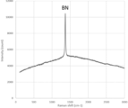
- FIG. 2 shows the results of Raman analysis of the boron nitride particles 1.
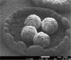
- FIG. 3 is a scanning electron microscope (SEM) photograph of the appearance of the boron nitride particles 1.
- FIG. 4(a) to (c) are scanning electron microscope (SEM) photographs of the cross section of the boron nitride particles 1.
- the cross section of the boron nitride particles of the present invention has linear voids. If the cross-sectional voids of the boron nitride particles are not streak-like, the cross-sectional voids of the boron nitride particles become large, and the thermal conductivity of the boron nitride particles becomes low. The voids in the cross section of the boron nitride particles formed by agglomeration of scale-like primary particles of boron nitride do not form streaks.
- the cross-sectional porosity (area ratio) of the boron nitride particles of the present invention is preferably 5% or less.
- the thermal conductivity of the boron nitride particles can be further increased.
- the cross-sectional porosity of the boron nitride particles is 5% or less, the resin does not enter the interior of the boron nitride particles, so the filling amount of the boron nitride particles in the heat dissipation sheet can be increased, thereby improving heat dissipation.
- the thermal conductivity of the sheet can be further increased.
- the cross-sectional porosity of the boron nitride particles is more preferably 4% or less, and still more preferably 3% or less.
- the lower limit of the range of the cross-sectional porosity of the boron nitride particles of the present invention is not particularly limited, but is usually 0.1% or more. Moreover, the lower limit may be 0.5% or more and 1.0% or more.
- the cross-sectional porosity of the boron nitride particles can be measured by the method described in Examples below.
- boron nitride particles formed by aggregating scaly primary particles of boron nitride it is difficult to densely aggregate (aggregate) the primary particles of boron nitride, so that the scaly primary particles of boron nitride are It is difficult to make the cross-sectional porosity of the aggregated boron nitride particles 5% or less.
- the ratio of length to width of the voids (length/width) is preferably 3-30.
- the ratio of the length to the width of the voids (length/width) is 3 or more, the porosity of the cross section of the boron nitride particles can be reduced, so that the thermal conductivity of the boron nitride particles can be increased. .
- the lower limit may be 5 or more and 10 or more.
- the ratio of the length to the width of the void (length/width) is 30 or less, the strength of the boron nitride particles can be increased. Destruction of particles can be suppressed. From this point of view, the ratio of the length to the width of the void (length/width) is more preferably 5-25, still more preferably 6-20, and even more preferably 10-20.
- the width of voids is preferably 0.5 ⁇ m or less.
- the width of the voids is 0.5 ⁇ m or less, the porosity of the cross section of the boron nitride particles can be reduced, so that the thermal conductivity of the boron nitride particles can be increased.
- the width of the gap is more preferably 0.4 ⁇ m or less, and still more preferably 0.3 ⁇ m or less.
- the lower limit of the range of void width is not particularly limited, but is usually 0.01 ⁇ m or more, may be 0.05 ⁇ m or more, or may be 0.1 ⁇ m or more. good.
- the width of voids in the cross section of the boron nitride particles can be measured by the method described in Examples below.
- the voids in the cross section of the boron nitride particles formed by aggregating the scaly primary particles of boron nitride are not streaky, the voids in the cross section of the boron nitride particles formed by aggregating the scaly primary particles of boron nitride are formed.
- the average width is greater than 0.5 ⁇ m.
- the cross section of the boron nitride particles of the present invention preferably has a plurality of voids, and at least one of the voids is preferably a streaky void along the circumferential direction.
- the streak-like void means a void having a ratio of length to width of 3 or more.
- half or more of the multiple voids in the cross section of the boron nitride particle of the present invention are linear voids along the circumferential direction, and the number of multiple voids in the cross section of the boron nitride particle of the present invention is more preferable. It is more preferable that two-thirds or more of the voids are linear voids along the circumferential direction, and all the voids of the plurality of voids in the cross section of the boron nitride particles of the present invention are along the circumferential direction. Streaky voids are even more preferable.
- the direction in which the linear voids extend in the cross section of the boron nitride particles can be measured by the method described in Examples below.
- the average particle size of the boron nitride particles of the present invention is not particularly limited, it is preferably 30 ⁇ m or less, more preferably 25 ⁇ m or less, and still more preferably 21 ⁇ m or less.
- the average particle size of the boron nitride particles of the present invention is preferably 1 ⁇ m or more, more preferably 2 ⁇ m or more, and still more preferably 3 ⁇ m or more.
- the average particle size of the boron nitride particles can be measured by the method described in Examples below.
- the crushing strength of the boron nitride particles of the present invention is preferably 10 MPa or more.
- the crushing strength of the boron nitride particles is 10 MPa or more, for example, it is possible to suppress the boron nitride particles from being broken while the resin and the boron nitride particles are mixed to produce a heat dissipation sheet. can.
- the crushing strength of the boron nitride particles of the present invention is more preferably 13 MPa or more, still more preferably 15 MPa or more, and even more preferably 20 MPa or more.
- the upper limit of the crushing strength range of the boron nitride particles of the present invention is not particularly limited, it is usually 40 MPa or less, may be 35 MPa or less, or may be 30 MPa or less.
- the crushing strength of boron nitride particles can be measured by the method described in Examples below.
- the average circularity of the boron nitride particles of the present invention is preferably 0.9 or more.
- the average circularity of the boron nitride particles is 0.9 or more, the flowability of the boron nitride particles is improved.
- resin and boron nitride particles are mixed to produce a heat dissipation sheet, it becomes easy to fill the resin with boron nitride particles, and the generation of voids in the heat dissipation sheet is suppressed. can do.
- the average circularity of the boron nitride particles of the present invention is more preferably 0.91 or more, still more preferably 0.92 or more, and even more preferably 0.95 or more.
- the upper limit of the average circularity range of the boron nitride particles of the present invention is not particularly limited, but is usually 0.99 or less, may be 0.97 or less, or may be 0.96 or less.
- the average circularity of boron nitride particles can be measured by the method described in Examples below.
- the boron nitride particles of the present invention can be produced, for example, by the following production method.
- An example of the method for producing boron nitride particles of the present invention will be described with reference to FIG.
- a mixture 2 containing boron carbide and boric acid is placed in a container 3 made of a carbon material whose opening is closed with a lid 4 made of a carbon material, A step of arranging the substrate 6 made of a carbon material under the lid 4 (placement step), and heating and pressurizing the inside of the container 3 in a nitrogen atmosphere, thereby removing the substrate 6 under the lid 3. and a step of generating boron nitride particles (generating step).
- the container 3 made of a carbon material is a container that can contain the mixture 2 described above.
- a substrate 5 made of a carbon material may be further arranged inside the container 3 .
- Said container 3 may be, for example, a carbon crucible.
- a lid 4 made of a carbon material closes the opening of the container 3 and increases the vapor pressure of the boron compound produced by heating the mixture 2 in the container 3 .
- the mixture 2 may be arranged at the bottom inside the container 3
- the substrate 5 may be arranged at the sidewall surface inside the container 3
- the substrate 6 may be arranged under the lid 4 .
- the substrates 5 and 6 made of a carbon material may be sheet-shaped, plate-shaped, or rod-shaped, for example.
- the substrates 5 and 6 made of carbon material may be, for example, carbon sheets (graphite sheets), carbon plates, or carbon rods.
- the boron carbide in the mixture 2 may be powdery (boron carbide powder), for example.
- the boric acid in the mixture 2 may be in powder form (boric acid powder), for example.
- Mixture 2 is obtained, for example, by mixing boron carbide powder and boric acid powder by a known method.
- Boron carbide powder can be produced by a known production method.
- a method for producing boron carbide powder for example, after mixing boric acid and acetylene black, the mixture is heated in an inert gas (eg, nitrogen gas) atmosphere at 1800 to 2400° C. for 1 to 10 hours to form lumps. Methods of obtaining boron carbide particles are mentioned.
- Boron carbide powder can be obtained by appropriately performing pulverization, sieving, washing, impurity removal, drying, and the like on the aggregated boron carbide particles obtained by this method.
- the average particle size of the boron carbide powder can be adjusted by adjusting the pulverization time of the lumpy carbon boron particles.
- the average particle size of the boron carbide powder may be 5 ⁇ m or more, 7 ⁇ m or more, or 10 ⁇ m or more, and may be 100 ⁇ m or less, 90 ⁇ m or less, 80 ⁇ m or less, or 70 ⁇ m or less.
- the average particle size of boron carbide powder can be measured by a laser diffraction scattering method.
- the mixing ratio of boron carbide and boric acid can be selected as appropriate.
- the content of boric acid in the mixture is preferably 2 parts by mass or more, more preferably 5 parts by mass or more, and still more preferably, with respect to 100 parts by mass of boron carbide, from the viewpoint that the boron nitride particles tend to be large. is 8 parts by mass or more, and may be 100 parts by mass or less, 90 parts by mass or less, or 80 parts by mass or less.
- the mixture containing boron carbide and boric acid may further contain other components.
- Other components include silicon carbide, carbon, iron oxide, and the like. Further containing silicon carbide in the mixture containing boron carbide and boric acid facilitates obtaining boron nitride particles having no open ends.
- the inside of the container 3 is a nitrogen atmosphere containing, for example, 95% by volume or more of nitrogen gas.
- the content of nitrogen gas in the nitrogen atmosphere is preferably 95% by volume or more, more preferably 99.9% by volume or more, and may be substantially 100% by volume.
- the nitrogen atmosphere may contain ammonia gas or the like in addition to the nitrogen gas.
- the heating temperature is preferably 1,300° C. or higher, more preferably 1,350° C. or higher, and still more preferably 1,400° C. or higher, from the viewpoint that the boron nitride particles tend to become large.
- the heating temperature may be 2100° C. or lower, 2000° C. or lower, or 1900° C. or lower.
- the pressure during pressurization is preferably 0.05 MPa or more, more preferably 0.3 MPa or more, and still more preferably 0.6 MPa or more, from the viewpoint that the boron nitride particles tend to become large.
- the pressure during pressurization may be 1.0 MPa or less, or 0.9 MPa or less.
- the time for heating and pressurizing is preferably 5 minutes or longer, more preferably 10 minutes or longer, from the viewpoint that the boron nitride particles tend to grow large.
- the time for heating and pressurizing may be 10 hours or less, or 5 hours or less.
- the boron nitride particles 1 described above are produced on the base material 6 placed under the lid 4 . Therefore, the boron nitride particles 1 are obtained by recovering the boron nitride particles 1 on the substrate 6 . Particles 1 generated on substrate 6 are boron nitride particles, part of the particles are recovered from the substrate, Raman analysis is performed on the recovered particles, and a peak derived from boron nitride is detected. can be confirmed by
- the reason why the boron nitride particles are formed on the substrate 6 by the above method is considered as follows.
- the mixture 2 in the container 3 is heated, the vapor pressure of the boron compound produced by heating the mixture 2 increases in the container 3 .
- droplets of the boron compound are formed on the surface of the base material 6 with the surface of the base material 6 arranged under the lid 4 serving as a nucleus.
- the vapor of the boron compound in the container 3 condenses on the surface of the droplet of the boron compound, and the droplet of the boron compound on the substrate 6 grows.
- the grown droplets are then nitrided.
- boron nitride particles on the substrate 6 placed under the lid 4 .
- the size of the droplets of the boron compound formed on the surface of the substrate 6 placed under the lid 4 can be controlled.
- a boron nitride powder having a desired average particle size with a small porosity for example, boron nitride particles having an average particle size of 5 ⁇ m or more and less than 30 ⁇ m and a small porosity can be obtained.
- the heat-dissipating sheet of the present invention is obtained by molding the thermally conductive resin composition containing the boron nitride particles of the present invention and a resin.
- resins used in the heat-dissipating sheet of the present invention include epoxy resins, silicone resins, silicone rubbers, acrylic resins, phenolic resins, melamine resins, urea resins, unsaturated polyesters, fluororesins, polyimides, polyamideimides, and polyetherimides.
- polybutylene terephthalate polyethylene terephthalate, polyphenylene ether, polyphenylene sulfide, wholly aromatic polyester, polysulfone, liquid crystal polymer, polyethersulfone, polycarbonate, maleimide modified resin, ABS (acrylonitrile-butadiene-styrene) resin, AAS (acrylonitrile-acrylic rubber ⁇ Styrene) resin, AES (acrylonitrile-ethylene-propylene-diene rubber-styrene) resin, and the like.
- ABS acrylonitrile-butadiene-styrene
- AAS acrylonitrile-acrylic rubber ⁇ Styrene
- AES acrylonitrile-ethylene-propylene-diene rubber-styrene
- the content of the boron nitride particles is 15% by volume or more and 20% by volume based on the total volume of the thermally conductive resin composition. Above, it may be 30% by volume or more, 40% by volume or more, 50% by volume or more, or 60% by volume or more.
- the content of boron nitride particles can suppress the formation of voids when the thermally conductive resin composition is formed into a sheet-shaped heat dissipating material, and can suppress deterioration in the insulating properties and mechanical strength of the sheet-shaped heat dissipating material. From the viewpoint, based on the total volume of the thermally conductive resin composition, it may be 85% by volume or less, 80% by volume or less, 70% by volume or less, 60% by volume or less, 50% by volume or less, or 40% by volume or less. .
- the content of the resin may be appropriately adjusted according to the application, required properties, and the like of the resin composition.
- the resin content is, for example, 15% by volume or more, 20% by volume or more, 30% by volume or more, 40% by volume or more, 50% by volume or more, or 60% by volume, based on the total volume of the thermally conductive resin composition. 85% by volume or less, 70% by volume or less, 60% by volume or less, 50% by volume or less, or 40% by volume or less.
- the thermally conductive resin composition may further contain a curing agent that cures the resin.
- a curing agent is appropriately selected according to the type of resin.
- curing agents used together with epoxy resins include phenol novolak compounds, acid anhydrides, amino compounds, imidazole compounds and the like, and imidazole compounds are preferably used.
- the content of the curing agent may be, for example, 0.5 parts by mass or more or 1 part by mass or more, and may be 15 parts by mass or less or 10 parts by mass or less with respect to 100 parts by mass of the resin.
- the thermally conductive resin composition may further contain other components.
- Other components may be curing accelerators (curing catalysts), coupling agents, wetting and dispersing agents, surface control agents, and the like.
- Curing accelerators include, for example, phosphorus-based curing accelerators such as tetraphenylphosphonium tetraphenylborate and triphenylphosphate; imidazole-based curing accelerators such as 2-phenyl-4,5-dihydroxymethylimidazole; Examples include amine-based curing accelerators such as boron trifluoride monoethylamine.
- coupling agents examples include silane-based coupling agents, titanate-based coupling agents, and aluminate-based coupling agents.
- Chemical bonding groups contained in these coupling agents include vinyl groups, epoxy groups, amino groups, methacryl groups, mercapto groups, and the like.
- wetting and dispersing agents include phosphate salts, carboxylic acid esters, polyesters, acrylic copolymers, block copolymers, and the like.
- surface modifiers examples include acrylic surface modifiers, silicone-based surface modifiers, vinyl-based modifiers, fluorine-based surface modifiers, and the like.
- the heat-dissipating sheet of the present invention can be prepared, for example, by blending the boron nitride particles of the present invention with a resin to prepare a thermally conductive resin composition (A), molding the thermally conductive resin composition into a sheet, It can be produced by a production method including the step (B) of producing a thermally conductive resin composition sheet and the step (C) of heating and pressurizing the thermally conductive resin composition sheet under vacuum.
- Step (A) In step (A), the boron nitride particles of the present invention and a resin are blended to produce a thermally conductive resin composition.
- the boron nitride particles and the resin used in step (A) have already been explained, so the explanation will be omitted.
- the thermally conductive resin composition is formed into a sheet to produce a thermally conductive resin composition sheet.
- the thermally conductive resin composition can be formed into a sheet by a doctor blade method or calendering.
- the thermally conductive resin composition passes through the calender rolls, the boron nitride particles in the thermally conductive resin composition may be destroyed. Therefore, it is preferable to mold the thermally conductive resin composition into a sheet by the doctor blade method.
- step (C) the thermally conductive resin composition sheet is heated and pressed under vacuum.
- the pressure of the vacuum environment when heating and pressurizing the thermally conductive resin composition sheet is preferably 0.1 to 5 kPa, more preferably 0.1 to 3 kPa.
- the heating temperature of the thermally conductive resin composition sheet is preferably 120 to 200.degree. C., more preferably 130 to 180.degree.
- the pressure when pressing the thermally conductive resin composition sheet is preferably 80 to 250 kg/cm 2 , more preferably 100 to 200 kg/cm 2 .
- the cross section of the boron nitride particles was observed using a scanning electron microscope (eg, "JSM-6010LA” (manufactured by JEOL Ltd.)) to examine the shape of the voids and the direction in which the linear voids extend.
- a scanning electron microscope eg, "JSM-6010LA” (manufactured by JEOL Ltd.)
- a cured resin was produced in the same manner as in the evaluation of the shape of voids and the direction in which streak-like voids extend, and osmium coating was applied to the cut surface cut with a diamond cutter. Then, the cross section of the boron nitride particles was photographed using a scanning electron microscope (for example, "JSM-6010LA” (manufactured by JEOL Ltd.) at a magnification of 3000 times for 10 fields of view. Using image analysis software (trade name: Mac-View, manufactured by Mountec Co., Ltd.), the captured image is binarized so that voids can be extracted from the captured image of the cross section of the boron nitride particles, and 10 fields of view. The area ratio of the porosity in the cross section of the boron nitride particles was measured for the image of , and the average value was taken as the porosity in the cross section of the boron nitride particles.
- a cured resin was produced in the same manner as in the evaluation of the shape of the voids and the direction in which the streaky voids extend, and the cut surface cut with a diamond cutter was polished. After fixing the cured resin with the cut surface polished to the sample table, the cut surface of the cured resin was coated with osmium. Then, the cross section of the boron nitride particles was photographed using a scanning electron microscope (for example, "JSM-6010LA" (manufactured by JEOL Ltd.) at a magnification of 3000 times for 10 fields of view.
- a scanning electron microscope for example, "JSM-6010LA" (manufactured by JEOL Ltd.) at a magnification of 3000 times for 10 fields of view.
- the photographed image of the cross section of the boron nitride particles was binarized so that the voids could be extracted. Then, for 100 pores, the maximum pore length and pore width are measured, and the average pore length and the average pore width are calculated as the pore width in the cross section of the boron nitride particles. and length. Then, the ratio of the length to the width of the void (length/width) was calculated.
- Average particle size SEM observation ( ⁇ 500) was performed on 50 particles collected from the substrate, and the average particle diameter was calculated from the 50 images.
- boron nitride particles 1 The aggregated boron carbide particles were pulverized by a pulverizer to obtain boron carbide powder having an average particle size of 10 ⁇ m. 100 parts by mass of the obtained boron carbide powder and 72 parts by mass of boric acid are mixed, filled in a carbon crucible, the opening of the carbon crucible is covered with a carbon sheet (manufactured by NeoGraf), and the lid of the carbon crucible and the carbon crucible The carbon sheet was fixed by sandwiching the carbon sheet with. Particles were generated on the carbon sheet by heating the capped carbon crucible in a resistance heating furnace under conditions of 1600° C. and 0.85 MPa for 10 minutes in a nitrogen gas atmosphere.
- the carbon sheet with particles was washed with hot water at 80°C. Then, the hot water used for washing was suction-filtered to recover the particles generated on the carbon sheet.
- Raman analysis was performed on the collected particles using a Raman spectrometer (manufactured by Horiba, Ltd., trade name "XploRA PLUS"). The results of this Raman analysis are shown in FIG. As can be seen from FIG. 2, only the peak derived from boron nitride was detected, confirming that boron nitride particles were produced.
- Boron nitride particles 2 were produced in the same manner as for boron nitride particles 1, except that the amount of boric acid was changed from 72 parts by mass to 36 parts by mass. Also, it was confirmed by Raman analysis that boron nitride particles were generated.
- Boron nitride particles 3 were produced in the same manner as for boron nitride particles 1, except that the amount of boric acid was changed from 72 parts by mass to 9 parts by mass. Also, it was confirmed by Raman analysis that boron nitride particles were generated.
- Boron nitride particles 4 were produced in the same manner as for boron nitride particles 1, except that the amount of boric acid was changed from 72 parts by mass to 100 parts by mass. Also, it was confirmed by Raman analysis that boron nitride particles were generated.
- Boric acid orthoboric acid
- HS100 acetylene black
- the synthesized boron carbide mass is pulverized in a ball mill for 3 hours, sieved to a particle size of 75 ⁇ m or less using a sieve, washed with an aqueous nitric acid solution to remove impurities such as iron, filtered and dried to reduce the average particle size to 10 ⁇ m.
- a boron carbide powder was produced.
- ⁇ Decarburization crystallization step> After mixing 100 parts by mass of the synthesized boron carbonitride and 100 parts by mass of boric acid using a Henschel mixer, the mixture was filled in a boron nitride crucible, and a resistance heating furnace was used at a pressure of 0.1 MPa under a nitrogen gas atmosphere. Then, the temperature was raised at a rate of 10°C/min from room temperature to 1200°C, and at a rate of 5°C/min from 1200°C, and the firing temperature was 2000°C for a holding time of 5 hours. Agglomerated boron nitride particles were synthesized in which the particles were agglomerated into agglomerates.
- boron nitride particles 5 were pulverized by 15 minutes using a Henschel mixer, they were classified with a nylon sieve having a sieve mesh of 150 ⁇ m using a sieve mesh. Boron nitride particles 5 were obtained by pulverizing and classifying the fired product. As a result of SEM observation, the obtained boron nitride particles 5 were agglomerated particles composed of agglomerated primary particles.
- Table 1 shows the evaluation results.
- SEM scanning electron microscope
- the shape of the cross-sectional voids was streaky, so the cross-sectional void ratio could be reduced.
- the shape of the cross-sectional voids was not streaky, so the cross-sectional void ratio was increased.
Landscapes
- Chemical & Material Sciences (AREA)
- Organic Chemistry (AREA)
- Health & Medical Sciences (AREA)
- Chemical Kinetics & Catalysis (AREA)
- Medicinal Chemistry (AREA)
- Polymers & Plastics (AREA)
- Inorganic Chemistry (AREA)
- Compositions Of Macromolecular Compounds (AREA)
Priority Applications (3)
| Application Number | Priority Date | Filing Date | Title |
|---|---|---|---|
| US18/723,859 US20250066197A1 (en) | 2021-12-27 | 2022-12-23 | Boron nitride particles and heat dissipation sheet |
| JP2023535489A JP7357181B1 (ja) | 2021-12-27 | 2022-12-23 | 窒化ホウ素粒子及び放熱シート |
| CN202280085704.6A CN118434671A (zh) | 2021-12-27 | 2022-12-23 | 氮化硼粒子及散热片材 |
Applications Claiming Priority (2)
| Application Number | Priority Date | Filing Date | Title |
|---|---|---|---|
| JP2021213164 | 2021-12-27 | ||
| JP2021-213164 | 2021-12-27 |
Publications (1)
| Publication Number | Publication Date |
|---|---|
| WO2023127742A1 true WO2023127742A1 (ja) | 2023-07-06 |
Family
ID=86999244
Family Applications (1)
| Application Number | Title | Priority Date | Filing Date |
|---|---|---|---|
| PCT/JP2022/047691 Ceased WO2023127742A1 (ja) | 2021-12-27 | 2022-12-23 | 窒化ホウ素粒子及び放熱シート |
Country Status (4)
| Country | Link |
|---|---|
| US (1) | US20250066197A1 (https=) |
| JP (1) | JP7357181B1 (https=) |
| CN (1) | CN118434671A (https=) |
| WO (1) | WO2023127742A1 (https=) |
Citations (7)
| Publication number | Priority date | Publication date | Assignee | Title |
|---|---|---|---|---|
| JP2018020932A (ja) * | 2016-08-03 | 2018-02-08 | デンカ株式会社 | 六方晶窒化ホウ素一次粒子凝集体及び樹脂組成物とその用途 |
| WO2018066277A1 (ja) * | 2016-10-07 | 2018-04-12 | デンカ株式会社 | 窒化ホウ素塊状粒子、その製造方法及びそれを用いた熱伝導樹脂組成物 |
| JP2018104260A (ja) * | 2016-12-28 | 2018-07-05 | 昭和電工株式会社 | 六方晶窒化ホウ素粉末、その製造方法、樹脂組成物及び樹脂シート |
| WO2018139642A1 (ja) * | 2017-01-30 | 2018-08-02 | 積水化学工業株式会社 | 樹脂材料及び積層体 |
| JP2018145090A (ja) * | 2018-03-28 | 2018-09-20 | 住友ベークライト株式会社 | 造粒粉、放熱用樹脂組成物、放熱シート、半導体装置、および放熱部材 |
| WO2020004600A1 (ja) * | 2018-06-29 | 2020-01-02 | デンカ株式会社 | 塊状窒化ホウ素粒子、窒化ホウ素粉末、窒化ホウ素粉末の製造方法、樹脂組成物、及び放熱部材 |
| WO2020194867A1 (ja) * | 2019-03-27 | 2020-10-01 | 富士フイルム株式会社 | 放熱シート前駆体、及び放熱シートの製造方法 |
-
2022
- 2022-12-23 WO PCT/JP2022/047691 patent/WO2023127742A1/ja not_active Ceased
- 2022-12-23 US US18/723,859 patent/US20250066197A1/en active Pending
- 2022-12-23 CN CN202280085704.6A patent/CN118434671A/zh active Pending
- 2022-12-23 JP JP2023535489A patent/JP7357181B1/ja active Active
Patent Citations (7)
| Publication number | Priority date | Publication date | Assignee | Title |
|---|---|---|---|---|
| JP2018020932A (ja) * | 2016-08-03 | 2018-02-08 | デンカ株式会社 | 六方晶窒化ホウ素一次粒子凝集体及び樹脂組成物とその用途 |
| WO2018066277A1 (ja) * | 2016-10-07 | 2018-04-12 | デンカ株式会社 | 窒化ホウ素塊状粒子、その製造方法及びそれを用いた熱伝導樹脂組成物 |
| JP2018104260A (ja) * | 2016-12-28 | 2018-07-05 | 昭和電工株式会社 | 六方晶窒化ホウ素粉末、その製造方法、樹脂組成物及び樹脂シート |
| WO2018139642A1 (ja) * | 2017-01-30 | 2018-08-02 | 積水化学工業株式会社 | 樹脂材料及び積層体 |
| JP2018145090A (ja) * | 2018-03-28 | 2018-09-20 | 住友ベークライト株式会社 | 造粒粉、放熱用樹脂組成物、放熱シート、半導体装置、および放熱部材 |
| WO2020004600A1 (ja) * | 2018-06-29 | 2020-01-02 | デンカ株式会社 | 塊状窒化ホウ素粒子、窒化ホウ素粉末、窒化ホウ素粉末の製造方法、樹脂組成物、及び放熱部材 |
| WO2020194867A1 (ja) * | 2019-03-27 | 2020-10-01 | 富士フイルム株式会社 | 放熱シート前駆体、及び放熱シートの製造方法 |
Also Published As
| Publication number | Publication date |
|---|---|
| US20250066197A1 (en) | 2025-02-27 |
| CN118434671A (zh) | 2024-08-02 |
| JPWO2023127742A1 (https=) | 2023-07-06 |
| JP7357181B1 (ja) | 2023-10-05 |
Similar Documents
| Publication | Publication Date | Title |
|---|---|---|
| JP7079378B2 (ja) | 窒化ホウ素粉末及びその製造方法、並びに、複合材及び放熱部材 | |
| TWI757686B (zh) | 氮化硼凝集粒子、氮化硼凝集粒子之製造方法、含有該氮化硼凝集粒子之樹脂組成物、成形體及片材 | |
| JP6682644B2 (ja) | 窒化ホウ素塊状粒子、その製造方法及びそれを用いた熱伝導樹脂組成物 | |
| TWI838500B (zh) | 塊狀氮化硼粒子、熱傳導樹脂組成物、以及散熱構件 | |
| CN104470873B (zh) | 带凹部的bn球状烧结粒子及其制造方法以及高分子材料 | |
| JPWO2020004600A1 (ja) | 塊状窒化ホウ素粒子、窒化ホウ素粉末、窒化ホウ素粉末の製造方法、樹脂組成物、及び放熱部材 | |
| JP7580512B2 (ja) | 窒化ホウ素粒子、樹脂組成物、及び樹脂組成物の製造方法 | |
| CN109311768A (zh) | 碳化硅的制备方法及碳化硅复合材料 | |
| WO2023210649A1 (ja) | β窒化ケイ素柱状粒子、複合粒子、放熱用焼結基板、樹脂複合物、及び、無機複合物、並びに、β窒化ケイ素柱状粒子の製造方法、複合粒子の製造方法 | |
| WO2020195298A1 (ja) | 粒状窒化ホウ素の製造方法および粒状窒化ホウ素 | |
| WO2023127729A1 (ja) | 窒化ホウ素粒子及び放熱シート | |
| WO2023127742A1 (ja) | 窒化ホウ素粒子及び放熱シート | |
| WO2022202827A1 (ja) | 窒化ホウ素粒子、その製造方法、及び樹脂組成物 | |
| JP7289019B2 (ja) | 窒化ホウ素粉末及び樹脂組成物 | |
| JP7106033B1 (ja) | 窒化ホウ素粒子、樹脂組成物、及び樹脂組成物の製造方法 | |
| JP7540834B2 (ja) | 窒化アルミニウム顆粒状粉末 | |
| JP7216872B2 (ja) | 窒化ホウ素粒子、樹脂組成物、及び樹脂組成物の製造方法 | |
| JP7158634B2 (ja) | 中空部を有する窒化ホウ素粒子を含有するシート | |
| JP7626356B2 (ja) | 窒化ホウ素粒子、窒化ホウ素粒子の製造方法、樹脂組成物、及び樹脂組成物の製造方法 | |
| KR101588292B1 (ko) | TaC 분말 및 이의 제조방법 | |
| TW202547780A (zh) | 氮化硼粉末及樹脂組成物 | |
| WO2024048377A1 (ja) | シートの製造方法及びシート | |
| WO2024048376A1 (ja) | 窒化ホウ素粒子、窒化ホウ素粒子の製造方法、及び樹脂組成物 | |
| JP2024173160A (ja) | 窒化ホウ素含有粉末、放熱フィラー、及び、樹脂組成物 | |
| CN119731118A (zh) | 氮化铝粉末和树脂组合物 |
Legal Events
| Date | Code | Title | Description |
|---|---|---|---|
| WWE | Wipo information: entry into national phase |
Ref document number: 2023535489 Country of ref document: JP |
|
| 121 | Ep: the epo has been informed by wipo that ep was designated in this application |
Ref document number: 22915965 Country of ref document: EP Kind code of ref document: A1 |
|
| WWE | Wipo information: entry into national phase |
Ref document number: 18723859 Country of ref document: US Ref document number: 202280085704.6 Country of ref document: CN |
|
| NENP | Non-entry into the national phase |
Ref country code: DE |
|
| 122 | Ep: pct application non-entry in european phase |
Ref document number: 22915965 Country of ref document: EP Kind code of ref document: A1 |
|
| WWP | Wipo information: published in national office |
Ref document number: 18723859 Country of ref document: US |