WO2023127500A1 - 制御装置、制御方法、及び制御プログラム - Google Patents
制御装置、制御方法、及び制御プログラム Download PDFInfo
- Publication number
- WO2023127500A1 WO2023127500A1 PCT/JP2022/046068 JP2022046068W WO2023127500A1 WO 2023127500 A1 WO2023127500 A1 WO 2023127500A1 JP 2022046068 W JP2022046068 W JP 2022046068W WO 2023127500 A1 WO2023127500 A1 WO 2023127500A1
- Authority
- WO
- WIPO (PCT)
- Prior art keywords
- target
- moving body
- projection
- control device
- information
- Prior art date
- Legal status (The legal status is an assumption and is not a legal conclusion. Google has not performed a legal analysis and makes no representation as to the accuracy of the status listed.)
- Ceased
Links
Images






Classifications
-
- G—PHYSICS
- G06—COMPUTING OR CALCULATING; COUNTING
- G06T—IMAGE DATA PROCESSING OR GENERATION, IN GENERAL
- G06T7/00—Image analysis
- G06T7/20—Analysis of motion
- G06T7/292—Multi-camera tracking
-
- G—PHYSICS
- G05—CONTROLLING; REGULATING
- G05D—SYSTEMS FOR CONTROLLING OR REGULATING NON-ELECTRIC VARIABLES
- G05D1/00—Control of position, course, altitude or attitude of land, water, air or space vehicles, e.g. using automatic pilots
- G05D1/60—Intended control result
- G05D1/656—Interaction with payloads or external entities
- G05D1/689—Pointing payloads towards fixed or moving targets
-
- B—PERFORMING OPERATIONS; TRANSPORTING
- B64—AIRCRAFT; AVIATION; COSMONAUTICS
- B64C—AEROPLANES; HELICOPTERS
- B64C39/00—Aircraft not otherwise provided for
- B64C39/02—Aircraft not otherwise provided for characterised by special use
-
- G—PHYSICS
- G03—PHOTOGRAPHY; CINEMATOGRAPHY; ANALOGOUS TECHNIQUES USING WAVES OTHER THAN OPTICAL WAVES; ELECTROGRAPHY; HOLOGRAPHY
- G03B—APPARATUS OR ARRANGEMENTS FOR TAKING PHOTOGRAPHS OR FOR PROJECTING OR VIEWING THEM; APPARATUS OR ARRANGEMENTS EMPLOYING ANALOGOUS TECHNIQUES USING WAVES OTHER THAN OPTICAL WAVES; ACCESSORIES THEREFOR
- G03B21/00—Projectors or projection-type viewers; Accessories therefor
-
- G—PHYSICS
- G05—CONTROLLING; REGULATING
- G05D—SYSTEMS FOR CONTROLLING OR REGULATING NON-ELECTRIC VARIABLES
- G05D1/00—Control of position, course, altitude or attitude of land, water, air or space vehicles, e.g. using automatic pilots
- G05D1/20—Control system inputs
- G05D1/24—Arrangements for determining position or orientation
- G05D1/243—Means capturing signals occurring naturally from the environment, e.g. ambient optical, acoustic, gravitational or magnetic signals
-
- G—PHYSICS
- G06—COMPUTING OR CALCULATING; COUNTING
- G06T—IMAGE DATA PROCESSING OR GENERATION, IN GENERAL
- G06T7/00—Image analysis
- G06T7/70—Determining position or orientation of objects or cameras
-
- G—PHYSICS
- G06—COMPUTING OR CALCULATING; COUNTING
- G06V—IMAGE OR VIDEO RECOGNITION OR UNDERSTANDING
- G06V20/00—Scenes; Scene-specific elements
- G06V20/10—Terrestrial scenes
-
- G—PHYSICS
- G06—COMPUTING OR CALCULATING; COUNTING
- G06V—IMAGE OR VIDEO RECOGNITION OR UNDERSTANDING
- G06V40/00—Recognition of biometric, human-related or animal-related patterns in image or video data
- G06V40/10—Human or animal bodies, e.g. vehicle occupants or pedestrians; Body parts, e.g. hands
-
- G—PHYSICS
- G05—CONTROLLING; REGULATING
- G05D—SYSTEMS FOR CONTROLLING OR REGULATING NON-ELECTRIC VARIABLES
- G05D1/00—Control of position, course, altitude or attitude of land, water, air or space vehicles, e.g. using automatic pilots
-
- G—PHYSICS
- G05—CONTROLLING; REGULATING
- G05D—SYSTEMS FOR CONTROLLING OR REGULATING NON-ELECTRIC VARIABLES
- G05D2105/00—Specific applications of the controlled vehicles
- G05D2105/70—Specific applications of the controlled vehicles for displaying or announcing information
-
- G—PHYSICS
- G05—CONTROLLING; REGULATING
- G05D—SYSTEMS FOR CONTROLLING OR REGULATING NON-ELECTRIC VARIABLES
- G05D2107/00—Specific environments of the controlled vehicles
- G05D2107/10—Outdoor regulated spaces
- G05D2107/17—Spaces with priority for humans, e.g. populated areas, pedestrian ways, parks or beaches
-
- G—PHYSICS
- G05—CONTROLLING; REGULATING
- G05D—SYSTEMS FOR CONTROLLING OR REGULATING NON-ELECTRIC VARIABLES
- G05D2109/00—Types of controlled vehicles
- G05D2109/20—Aircraft, e.g. drones
- G05D2109/25—Rotorcrafts
- G05D2109/254—Flying platforms, e.g. multicopters
-
- G—PHYSICS
- G05—CONTROLLING; REGULATING
- G05D—SYSTEMS FOR CONTROLLING OR REGULATING NON-ELECTRIC VARIABLES
- G05D2111/00—Details of signals used for control of position, course, altitude or attitude of land, water, air or space vehicles
- G05D2111/10—Optical signals
-
- H—ELECTRICITY
- H04—ELECTRIC COMMUNICATION TECHNIQUE
- H04N—PICTORIAL COMMUNICATION, e.g. TELEVISION
- H04N9/00—Details of colour television systems
- H04N9/12—Picture reproducers
- H04N9/31—Projection devices for colour picture display, e.g. using electronic spatial light modulators [ESLM]
Definitions
- the present invention relates to a control device, control method, and control program.
- Patent Document 1 describes that a mobile projection device projects and displays a projection image to a determined location while hovering.
- Patent Literature 2 describes that the multicopter is equipped with a human sensor and projects an image onto the road surface only when there is a person near the multicopter.
- One embodiment according to the technology of the present disclosure provides a control device, control method, and control program capable of performing better projection.
- a control device is a control device that includes a processor and controls a moving body equipped with a projection device, wherein the processor acquires first target information regarding a state of a first target, 1 determining a projection target position and a target moving body position based on target information, moving the moving body to the target moving body position, projecting the projection target position from the projection device, and moving the moving body to the target movement; Second object information regarding the state of the first object is obtained while moving to the body position, and the projection object position and/or the target moving body position are updated based on the second object information.
- a processor of a control device that controls a moving body equipped with a projection device acquires first target information regarding a state of a first target, and based on the first target information, a projection target determining a position and a target moving body position, moving the moving body to the target moving body position, projecting from the projection device onto the projection target position, and moving the moving body to the target moving body position, Second object information relating to the state of the first object is acquired, and the projection object position and/or the target moving body position are updated based on the second object information.
- a control program acquires first target information about a state of a first target in a processor of a control device that controls a moving body equipped with a projection device, and based on the first target information, a projection target determining a position and a target moving body position, moving the moving body to the target moving body position, projecting from the projection device onto the projection target position, and moving the moving body to the target moving body position, It is for executing processing of acquiring second object information relating to the state of the first object and updating the projection object position and/or the target moving body position based on the second object information.
- FIG. 1 is a diagram showing an example of a configuration of a mobile body 10
- FIG. 2 is a schematic diagram showing an example of the internal configuration of the projection device 11
- FIG. 4 is a flowchart showing a first example of control by the control device 14
- 5 is a diagram (Part 1) showing an example of the operation of the moving body 10 under the control of the control device 14 shown in FIG. 4
- FIG. 5 is a diagram (part 2) showing an example of the operation of the moving body 10 under the control of the control device 14 shown in FIG. 4
- FIG. 5 is a diagram (part 3) showing an example of the operation of the moving body 10 under the control of the control device 14 shown in FIG. 4
- FIG. 1 is a diagram showing an example of a configuration of a mobile body 10
- FIG. 2 is a schematic diagram showing an example of the internal configuration of the projection device 11
- FIG. 4 is a flowchart showing a first example of control by the control device 14
- 5 is a diagram (Part 1) showing an example of the
- FIG. 14 is a flowchart showing a fourth example of control by the control device 14; 10 is a flowchart showing a fifth example of control by the control device 14; It is a figure which shows an example of the information terminal 110 to which the control apparatus of this invention is applied.
- 2 is a diagram illustrating an example of a hardware configuration of an information terminal 110; FIG.
- FIG. 1 is a diagram showing an example of a mobile object 10 according to an embodiment.
- the moving object 10 is a movable flying object, such as an unmanned aerial vehicle called a drone.
- the moving body 10 is a multicopter having three or more rotors (eg, four rotors).
- the control device of the present invention is mounted on a moving body 10, for example.
- a moving body 10 is equipped with a projection device 11 .
- the projection device 11 is a projection device capable of projecting onto the projection target 6 .
- the projection target 6 is an object such as a wall or a screen that has a projection surface on which a projection image can be displayed by the projection device 11 .
- the projection object 6 is a cuboid.
- a projection target area 7 indicated by a dashed line is an area of the projection object 6 that is irradiated with projection light from the projection device 11 .
- the projection target region 7 corresponds to part or all of the projectable range that can be projected by the projection device 11 .
- the projection area 7 is rectangular.
- the mobile object 10 flies over the head of the person 1 and projects an image from the mounted projection device 11 onto the projection target area 7 .
- a person 1 is an observer viewing a projection image projected onto the projection target area 7 by the projection device 11 .
- Person 1 is an example of the first object of the present invention.
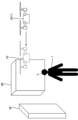
- FIG. 2 is a diagram showing an example of the configuration of the moving body 10.
- the moving body 10 includes, for example, a projection device 11, an imaging device 12, a control device 14, a communication section 15, and a movement mechanism 16.
- the projection device 11 is configured by, for example, a liquid crystal projector or a projector using LCOS (Liquid Crystal On Silicon). In the following description, the projection device 11 is assumed to be a liquid crystal projector.
- LCOS Liquid Crystal On Silicon
- the imaging device 12 is an imaging unit including an imaging lens and an imaging device.
- the imaging element for example, a CMOS (Complementary Metal-Oxide-Semiconductor) image sensor can be used.
- CMOS Complementary Metal-Oxide-Semiconductor
- the control device 14 is an example of the control device of the present invention.
- the control device 14 performs various controls in the moving body 10 .
- Control by the control device 14 includes, for example, control of projection by the projection device 11, control of imaging by the imaging device 12, control of communication by the communication unit 15, control of movement of the moving body 10 by the movement mechanism 16, is included.
- the control device 14 includes a control unit configured by various processors, a communication interface (not shown) for communicating with each unit, and a storage medium such as a hard disk, SSD (Solid State Drive), or ROM (Read Only Memory). 14a, and controls the moving body 10 in an integrated manner.
- the various processors of the control unit of the control device 14 the circuit configuration is changed after manufacturing such as CPU (Central Processing Unit), FPGA (Field Programmable Gate Array), which is a general-purpose processor that executes programs and performs various processes.
- Programmable Logic Device which is a processor, or dedicated electric circuit, etc., which is a processor having a circuit configuration specially designed to execute specific processing such as ASIC (Application Specific Integrated Circuit) is included.
- control unit of the control device 14 may be configured with one of various processors, or a combination of two or more processors of the same or different type (for example, a combination of multiple FPGAs or a combination of a CPU and an FPGA). may consist of
- the communication unit 15 is a communication interface capable of communicating with other devices.
- the communication unit 15 is, for example, a radio communication interface that performs radio communication with an information terminal on the ground while the mobile object 10 is in flight.
- the moving mechanism 16 is a mechanism for moving the moving body 10 .
- the moving mechanism 16 includes four rotors, actuators such as motors that rotate the rotors, and control circuits that control the actuators.
- the number of rotors or the like included in the moving mechanism 16 may be three, or may be five or more.
- the projection device 11, the imaging device 12, the control device 14, the communication unit 15, and the moving mechanism 16 are implemented as, for example, one device.
- the projection device 11, the imaging device 12, the control device 14, the communication unit 15, and the movement mechanism 16 may be implemented by a plurality of devices that can cooperate by communicating with each other.
- FIG. 3 is a schematic diagram showing an example of the internal configuration of the projection device 11.
- the projection device 11 of the moving body 10 shown in FIG. 2 includes a light source 31, an optical modulator 32, a projection optical system 33, and a control circuit 34, as shown in FIG.
- the light source 31 includes a light emitting element such as a laser or an LED (Light Emitting Diode), and emits white light, for example.
- the light modulation unit 32 modulates each color light emitted from the light source 31 and separated into three colors of red, blue, and green by a color separation mechanism (not shown) based on image information, and outputs each color image. It is composed of a liquid crystal panel (light modulation element) and a dichroic prism that mixes the respective color images emitted from the three liquid crystal panels and emits them in the same direction. Red, blue, and green filters may be mounted on these three liquid crystal panels, respectively, and the white light emitted from the light source 31 may be modulated by each liquid crystal panel to emit an image of each color.
- the projection optical system 33 receives the light from the light source 31 and the light modulation section 32, and includes at least one lens and is configured by, for example, a relay optical system. The light that has passed through the projection optical system 33 is projected onto the projection object 6 .
- a region of the projection object 6 irradiated with light that passes through the entire range of the light modulation unit 32 is a projectable range that can be projected by the projection device 11 .
- the area irradiated with the light that is actually transmitted from the light modulation section 32 is the projection range (projection target area 7) of the projection device 11 .
- the size, position, and shape of the projection range of the projection device 11 change in the projectable range.
- the control circuit 34 controls the light source 31, the light modulating unit 32, and the projection optical system 33 based on the display data input from the control device 14, thereby projecting an image on the projection object 6 based on the display data. be projected.
- the display data input to the control circuit 34 is made up of three data, ie, red display data, blue display data, and green display data.
- control circuit 34 enlarges or reduces the projection range of the projection device 11 by changing the projection optical system 33 based on commands input from the control device 14 . Further, the control circuit 34 may move the projection range of the projection device 11 by changing the projection optical system 33 based on a command input from the control device 14 .
- the projection device 11 also includes a shift mechanism that mechanically or optically moves the projection range of the projection device 11 while maintaining the image circle of the projection optical system 33 .
- the image circle of the projection optical system 33 is an area in which the projection light incident on the projection optical system 33 passes through the projection optical system 33 appropriately in terms of light falloff, color separation, peripheral curvature, and the like.
- the shift mechanism is realized by at least one of an optical system shift mechanism that performs optical system shift and an electronic shift mechanism that performs electronic shift.
- the optical system shift mechanism is, for example, a mechanism for moving the projection optical system 33 in a direction perpendicular to the optical axis, or a mechanism for moving the light modulation section 32 in a direction perpendicular to the optical axis instead of moving the projection optical system 33. is. Further, the optical system shift mechanism may combine the movement of the projection optical system 33 and the movement of the light modulation section 32 .
- the electronic shift mechanism is a mechanism that shifts the pseudo projection range by changing the light transmission range in the light modulation section 32 .
- the projection device 11 may also include a projection direction changing mechanism that moves the projection range together with the image circle of the projection optical system 33 .
- the projection direction changing mechanism is a mechanism that changes the projection direction of the projection device 11 by changing the orientation of the projection device 11 by mechanical rotation.
- FIG. 4 is a flow chart showing a first example of control by the control device 14. As shown in FIG. The control device 14 executes the processing shown in FIG. 4, for example.
- the control device 14 detects the person 1 from the imaging result of the imaging device 12 and detects the state of the detected person 1 (step S11). For example, the control device 14 detects the person 1 by performing image recognition processing based on an image captured by the imaging device 12, and detects the position of the eyes of the person 1 (direction of line of sight), , the movement state (speed or direction) of the person 1, and at least one of the number of persons 1 are detected as the state of the person 1.
- the control device 14 determines the optimal projection target position for observation from the person 1 (step S12). Specifically, the control device 14 identifies projection candidate positions where projection is possible from the imaging results of the imaging device 12, and selects the projection candidate positions most suitable for observation from the person 1 from the identified projection candidate positions. is determined as the projection target position. For example, the control device 14 controls the projection candidate position in the direction the person 1 is looking, the projection candidate position in the direction the person 1 is facing, the projection candidate position in the movement destination of the person 1, or a projection candidate position that is visible from a plurality of persons. A projection candidate position or the like at the position is determined as a projection target position.
- the control device 14 determines the optimal target moving body position for projection onto the projection target position determined in step S12 (step S13). Specifically, the control device 14 identifies movement candidate positions to which the moving body 10 can move from the imaging results of the imaging device 12, and selects the movement candidate positions that are most suitable for projection onto the projection target position. Then, the candidate moving position obtained is determined as the target moving body position. As an example, the control device 14 determines, as the target moving body position, the moving candidate position at which the projection of the projection target position on the projection plane minimizes, among the moving candidate positions to which the moving body 10 can move. However, the control device 14 may determine the target moving body position based on other factors such as the presence or absence of an obstacle on the optical path of the projection light, not limited to the tilt of the projection.
- control device 14 controls the moving mechanism 16 to start moving the moving body 10 to the target moving body position determined in step S13 (step S14).
- control device 14 acquires the current position of the moving body 10 (step S15).
- the control device 14 acquires the position of the mobile object 10 by GNSS (Global Navigation Satellite System) such as GPS (Global Positioning System) provided in the mobile object 10 .
- GNSS Global Navigation Satellite System
- GPS Global Positioning System
- control device 14 determines whether or not the moving body 10 has reached the target moving body position based on the position of the moving body 10 acquired in step S15 (step S16). If the moving body 10 has not reached the target moving body position (step S16: No), the control device 14 detects the state of the person 1 from the imaging result of the imaging device 12 (step S17), as in step S11. ).
- step S18 determines whether or not the optimal projection target position has changed. For example, as in step S12, the control device 14 selects a projection candidate position that is most suitable for observation from the person 1 from among the projection candidate positions that can be projected, and the selected projection candidate position is the current projection target. The determination in step S18 is made depending on whether or not there is a change from the position. If the optimal projection target position has not changed (step S18: No), the control device 14 returns to step S15.
- step S18 if the optimal projection target position has changed (step S18: Yes), the control device 14 updates the projection target position (step S19). Specifically, the control device 14 determines the projection candidate position selected in step S18 as a new projection target position.
- control device 14 determines the optimal target moving body position for projection onto the projection target position updated in step S12 (step S20), and returns to step S15. Specifically, in the same way as in step S13, the control device 14 identifies movement candidate positions to which the moving body 10 can move from the imaging result of the imaging device 12, and selects the projection target positions from the identified movement candidate positions. , is determined as the target moving body position.
- step S16 when the moving body 10 reaches the target moving body position (step S16: Yes), the control device 14 controls the projection device 11 to start projecting an image onto the projection target position (step S21), the series of processing ends. As a result, the moving body 10 is in a state of projecting an image onto the projection target position at the target moving body position.
- FIGS. 5 to 7 are diagrams showing an example of the operation of the moving body 10 under the control of the control device 14 shown in FIG. 5 to 7, a first projection object 6A and a second projection object 6B are positioned around the person 1, and are projected by the projection device 11 in the same manner as the projection object 6 shown in FIG. An object that has a projection surface on which an image can be displayed.
- the person 1 faces the direction of the second projection object 6B.
- the control device 14 detects the person 1 from the imaging result of the imaging device 12 and also detects the state of the person 1 .
- the control device 14 cannot detect that the person 1 is facing the direction of the second projection object 6B due to the long distance between the moving object 10 (imaging device 12) and the person 1. , and as a result, the optimum projection target position for observation from the person 1 is determined as the first projection target object 6A.
- the control device 14 determines the first position P1 as the target moving body position that is most suitable for projection onto the first projection object 6A. In this case, the control device 14 controls the moving mechanism 16 to start moving the moving body 10 to the first position P1.
- the control device 14 repeatedly determines whether or not the optimal projection target position has changed based on the imaging results of the imaging device 12. Then, in the state shown in FIG. 6, the control device 14 detects that the person 1 is facing the direction of the second projection object 6B, and as a result, the optimal projection object position for observation from the person 1 is the second projection object. Assume that it is determined to be the second projection object 6B. In this case, the control device 14 updates the projection target position to the second projection target 6B.
- control device 14 determines the second position P2 as the optimal target moving body position for projection onto the second projection object 6B. In this case, the control device 14 changes the destination of the moving body 10 to the second position P2. Then, when the moving body 10 reaches the second position P2, the control device 14 controls the moving mechanism 16 to move from the projection device 11 to the second projection object 6B (projection target position), as shown in FIG. Start image projection.
- the control device 14 acquires the detection result (first object information) of the state of the person 1 (first object), determines the projection target position and the target moving body position based on the detection result, The moving body 10 is moved to the moving body position, and the projection device 11 projects to the projection target position. That is, the control device 14 causes the projection device 11 to project to the projection target position in a state in which the moving body 10 has reached the target moving body position.
- control device 14 acquires the detection result (second target information) of the state of the person 1 even while the moving body 10 is moving to the target moving body position, and based on the detection result, the projection target position and the target position are obtained. Update the mobile position.
- the projection target position and the target moving body position that are determined to be optimal change during the movement of the moving body 10 can be flexibly updated. If the projection target position or the target moving body position that is determined to be optimal changes during the movement of the moving body 10, for example, a situation that could not be determined from a distance becomes clear during the movement of the moving body 10, and the optimal projection is performed. This includes a case where the target position changes, a case where the state of the person 1 or the projection target changes while the moving body 10 is moving, and the like.
- projection can be performed from a better target moving body position to a better projection target position to improve the projection quality, or the time required to move to the optimum target moving body position in a short time and start projection can be improved. can be shortened. That is, better projection can be performed.
- the detection result of the state of person 1 is information obtained by imaging person 1 with imaging device 12 .
- the control device 14 performs the process of detecting the state of the person 1 from the imaging result of the imaging device 12 has been described. or another device that can communicate with the control device 14 may be configured to perform this processing.
- the imaging device 12 Since the imaging device 12 is mounted on the moving body 10, the optimum projection target position based on the imaging result of the imaging device 12 tends to change during the movement of the moving body 10.
- the imaging device When the projection target position and the target moving body position determined to be optimal based on the imaging result by 12 change during the movement of the moving body 10, the projection target position and the target moving body position can be flexibly updated.
- the configuration in which the imaging device 12 is mounted on the moving body 10 is not limited to the configuration in which the imaging device 12 is provided on the ground as long as the imaging device 12 can communicate with the control device 14.
- a configuration in which the imaging device 12 is provided in a moving object (for example, a flying object) different from the moving object 10 may be employed.
- FIG. 8 is a flowchart showing a second example of control by the control device 14. As shown in FIG. The control device 14 may execute the processing shown in FIG.
- Steps S31 to S35 shown in FIG. 8 are the same as steps S11 to S15 shown in FIG.
- the control device 14 determines whether or not the moving body 10 has entered the update stop area based on the position of the moving body 10 acquired in step S35 (step S36).
- the update stop area is a predetermined area including the target moving body position. The update stop area will be explained in FIG.
- step S36 if the moving body 10 has not entered the update stop area (step S36: No), the control device 14 proceeds to step S37.
- Steps S37 to S40 are the same as steps S17 to S20 shown in FIG.
- step S36 if the moving body 10 has entered the update stop area (step S36: Yes), the control device 14 determines whether the moving body 10 is at the target moving body position based on the position of the moving body 10 acquired in step S35. (step S41), and waits until the moving body 10 reaches the target moving body position (step S41: No loop).
- step S41 when the moving body 10 reaches the target moving body position (step S41: Yes), the control device 14 performs control to start projecting an image from the projection device 11 to the projection target position (step S42). , ends the series of processes.
- FIG. 9 is a diagram showing an example of an update stop area under the control of the control device 14 shown in FIG.
- the same reference numerals are given to the same parts as those shown in FIG. 5, and the description thereof will be omitted.
- the target moving body position is the first position P1.
- the control device 14 stops updating the projection target position and the target moving body position. .
- the update stop area E1 is an area in which the distance from the target moving body position (first position P1) in the movement direction of the moving body 10 is equal to or less than a predetermined distance. That is, when the distance between the moving body 10 and the target moving body position becomes equal to or less than the predetermined distance, the control device 14 stops updating the projection target position and the target moving body position.
- the update stop area E1 is not limited to the example shown in FIG. or a region of another shape. Also, the update stop area E1 may be an area centered on a position shifted from the target moving body position (for example, a position shifted in the direction of the moving body 10).
- FIG. 10 is a flow chart showing a third example of control by the control device 14. As shown in FIG. The control device 14 may perform the processing shown in FIG. 10 .
- Steps S51 to S57 shown in FIG. 10 are the same as steps S11 to S17 shown in FIG.
- the control device 14 calculates an updatable area according to the distance between the moving body 10 and the target moving body position (step S58). Calculation of the updatable area according to the distance between the moving body 10 and the target moving body position will be described with reference to FIG.
- Steps S59 to S62 shown in FIG. 10 are the same as steps S18 to S21 shown in FIG. However, in step S59, the control device 14 selects the most suitable projection position for observation from the person 1 from among the projection candidate positions where projection is possible and included in the updatable area calculated in step S58. Select a candidate position. Then, the control device 14 determines whether the optimum projection target position has changed based on whether the selected projection candidate position has changed from the current projection target position.
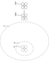
- FIG. 11 is a diagram showing an example of an updatable area under the control of the control device 14 shown in FIG. FIG. 11 shows the moving body 10 as viewed vertically from above. In the state of FIG. 11, it is assumed that the target moving body position is the first position P1.
- the first updatable area e1 is the updatable area calculated when the mobile unit 10 is located at the first position p1.
- a second updatable area e2 is an updatable area calculated when the mobile unit 10 is located at the second position p2.
- the second position p2 is closer to the first position P1 than the first position p1.
- Both the first updatable area e1 and the second updatable area e2 are areas including the first position P1 (target moving body position), but the second updatable area e2 is narrower than the first updatable area e1. is. Also, in FIG. 11, both the first updatable area e1 and the second updatable area e2 are horizontal elliptical areas.
- the control device 14 narrows the updatable area as the distance between the moving object 10 and the target moving object position becomes shorter.
- the moving body 10 approaches the target moving body position, a large change in the projection target position and the target moving body position is suppressed, and fluctuations in the movement of the moving body 10 can be prevented.
- the first updatable area e1 and the second updatable area e2 are not limited to the example shown in FIG. 11, and may have various shapes.
- first updatable area e1 and the second updatable area e2 may be areas centered on the target moving body position, or may be at positions shifted from the target moving body position (for example, shifted in the direction of the moving body 10). It may be a region centered on the position where the
- FIG. 12 is a diagram showing an example of an imaging device not mounted on the moving object 10.
- the control device 14 may be able to communicate with the imaging device 12a that is not mounted on the moving object 10 .
- the imaging device 12a may be installed, for example, on the ground near the projection target 6, or may be mounted on a moving body different from the moving body 10 (for example, another flying body).
- control device 14 receives an image captured by the imaging device 12a from the imaging device 12a, and combines the imaging result of the imaging device 12 mounted on the moving object 10 with the imaging result of the imaging device 12a.
- the first object information about the state of the person 1 (first object) may be acquired.
- FIG. 13 is a diagram showing an example of a situation in which person 1 looks at moving object 10.
- the control device 14 detects a state in which the person 1 is looking at the moving object 10, for example, based on the imaging result of the imaging device 12.
- FIG. For example, the control device 14 detects the orientation of the face and the direction of the line of sight of the person 1 through image recognition processing based on the captured image obtained by the imaging device 12, thereby detecting the state in which the person 1 is looking at the moving body 10. detect.
- the control device 14 When the control device 14 detects that the person 1 is looking at the moving body 10, the control device 14 excludes the state of the person 1 detected in that state and determines or updates the projection target position. For example, when the control device 14 detects that the person 1 is looking at the moving body 10, the control device 14 determines that the state of the person 1 that was detected immediately before detecting that the person 1 is looking at the moving body 10 continues. Then, the projection target position is determined and updated.
- control device 14 may determine the projection target position by excluding changes in the state detection result (first target information) of the person 1 caused by the moving object 10 . This makes it possible to accurately select a more appropriate projection target position and target moving body position.
- FIG. 14 is a flowchart showing a fourth example of control by the control device 14. As shown in FIG. The control device 14 may execute the processing shown in FIG. 14 .
- Steps S71 to S81 shown in FIG. 14 are the same as steps S11 to S21 shown in FIG. However, after performing control to start projecting the image from the projection device 11 to the projection target position in step S81, the control device 14 proceeds to step S77.
- the control device 14 keeps the state of the person 1 ( acquisition of the second target information) and update of the projection target position and the target moving body position based on the acquired state of the person 1 are continued.
- the target moving body position is updated, the moving body 10 does not reach the target moving body position, so the moving body 10 is moved to the updated target moving body position again.
- the projection target position and the target moving body position can be flexibly updated.
- FIG. 15 is a flowchart showing a fifth example of control by the control device 14. As shown in FIG. The control device 14 may execute the processing shown in FIG. 15 .
- Steps S91 to S99 shown in FIG. 15 are the same as steps S11 to S19 shown in FIG.
- the control device 14 determines whether or not the moving body 10 has entered the moving body position update stop area based on the position of the moving body 10 acquired in step S35 (step S100).
- the mobile position update stop area is the same area as the update stop area described in FIGS.
- the moving object position update stop area is an area where updating of the target moving object position is stopped, but updating of the projection target position is not stopped.
- step S100 if the moving body 10 is not in the moving body position update stop area (step S100: No), the control device 14 proceeds to step S101 and updates the target moving body position. Steps S101 and S102 shown in FIG. 15 are the same as steps S20 and S21 shown in FIG. If the moving body 10 has entered the moving body position update stop area (step S100: Yes), the control device 14 maintains the target moving body position and returns to step S95.
- the control device 14 maintains the target moving body position when the moving body 10 is located within the moving body position update stop area (predetermined area) including the target moving body position and the projection target position is updated. You may do so.
- the optimum target position of the moving body changes when the moving body 10 approaches the target position to some extent, the target position of the moving body is maintained and only the projection direction is changed to change the projection target position. can be done.
- the first target may be a plurality of persons.
- the control device 14 acquires first object information indicating the states of the plurality of persons, and projects based on the acquired first object information. Determine the target position and the target moving body position.
- the first target information is, for example, at least one of the eye positions (line-of-sight directions) of the plurality of persons, the orientation of the bodies of the plurality of persons, the positional relationship of the plurality of persons, and the movement state of the plurality of persons. be.
- the control device 14 calculates an evaluation value of ease of observation from a plurality of persons for each projection candidate position where projection is possible, and sets the projection candidate position with the highest calculated evaluation value as the projection target position. decide. For example, if the plurality of persons are two persons, a first person and a second person, the evaluation value of the ease of observation from the plurality of persons is the same as the evaluation value of the ease of observation from the first person. , an evaluation value of ease of observation from the second person, and a representative value (for example, total, average, minimum value, etc.). The average may be a weighted average.
- the first object may be something other than a person.
- the first object may be a car in which a person rides.
- the control device 14 acquires, for example, the detection result of the orientation of the vehicle as the detection result of the state of the vehicle (first target).
- the first target is not limited to the projection observer or the car in which the projection observer appears, but may be a projection object that is a candidate for the projection target position.
- the control device 14 may acquire projection plane information regarding the state of the projection plane of the object to be projected (whether or not it has a plane suitable for projection, etc.) as the first object information.
- the control device 14 acquires the detection result (first object information) of the state of the object to be projected (first object), determines the projection object position and the target moving object position based on the detection result, The moving body 10 is moved to the moving body position, and the projection device 11 projects to the projection target position. Then, the control device 14 acquires the detection result (second target information) of the state of the projection target even while the moving body 10 is moving to the target moving body position, and based on the detection result, the projection target position and the Update the target moving body position.
- the projection target position and the target moving body position that are determined to be optimal change during the movement of the moving body 10 can be flexibly updated. If the projection target position and the target moving body position that are determined to be optimal change while the moving body 10 is moving, for example, a situation (for example, the state of the projection surface) that cannot be determined from a distance may change while the moving body 10 is moving. This includes a case where the optimal projection target position has changed due to a change in the state of the object to be projected during the movement of the moving body 10, and the like.
- projection can be performed from a better target moving body position to a better projection target position to improve the projection quality, or the time required to move to the optimum target moving body position in a short time and start projection can be improved. can be shortened. That is, better projection can be performed.
- the first target may include both a person (or an automobile in which the person rides, etc.) and a projection target that is a candidate for the projection target position.
- the control device 14 acquires, for example, the detection result (first object information) of the state of the person and projection object (first object), and determines the projection object position and the target moving body position based on the detection result. Then, the moving body 10 is moved to the target moving body position and projected from the projection device 11 to the projection target position. Then, the control device 14 acquires the detection result (second target information) of the states of the person and the projection target even while the moving body 10 is moving to the target moving body position, and based on the detection result, the projection target Update the position and the target mobile body position.
- the control device 14 may change the method of determining the projection target position based on the state of the first target (first target information) based on the distance between the moving body 10 and the target moving body position. As an example, the control device 14 determines the projection target position based on the position of the person 1 detected from the imaging result of the imaging device 12 and the orientation of the person 1 detected from the imaging result of the imaging device 12 .
- control device 14 calculates the first evaluation value of ease of observation calculated from the detected position of the person 1 and the direction of the detected person 1 for each projection candidate position where projection is possible.
- a total evaluation value is calculated by ⁇ ⁇ first evaluation value + ⁇ ⁇ second evaluation value based on the second evaluation value of ease of observation, and the projection candidate position with the highest calculated total evaluation value is projected. Determine as the target position.
- the control device 14 for example, when the distance between the moving body 10 and the target moving body position is equal to or greater than a predetermined distance, sets coefficients ⁇ and ⁇ such that ⁇ > ⁇ , and calculates the overall evaluation value. , set coefficients ⁇ and ⁇ such that ⁇ when the distance between the moving body 10 and the target moving body position is less than a predetermined distance, and calculate the overall evaluation value.
- the control device 14 sets the first value to ⁇ to calculate the overall evaluation value.
- the second value may be set to ⁇ to calculate the overall evaluation value. First value ⁇ Second value.
- the position of the person 1 is emphasized rather than the direction of the person 1 to determine the projection target position.
- the projection target position can be determined with more emphasis on the direction of the person 1 than on the position of the person 1 .
- the position of the person 1 is emphasized in determining the projection target position, and the moving body 10 approaches the person 1.
- the projection target position is determined in consideration of the orientation of the person 1 so that the person 1 can be observed more easily.
- a projection target position can be determined.
- the moving object 10 is a multicopter
- the moving object 10 may be an aircraft (flying object) other than the multicopter.
- the moving object 10 is not limited to a flying object, and may be a vehicle, a robot, or the like that runs or walks on the ground.
- the control device 14 may be configured to update either the projection target position or the target moving body position.
- the control device 14 acquires the detection result (second target information) of the state of the person 1 while the mobile body 10 is moving to the target mobile body position, and updates the projection target position based on the detection result.
- the projection target position can be flexibly updated. Therefore, it is possible to improve the projection quality by performing projection on a better projection target position. That is, better projection can be performed.
- the control device 14 acquires the detection result (second target information) of the state of the person 1 while the mobile body 10 is moving to the target mobile body position, and updates the target mobile body position based on the detection result. do.
- the target moving body position determined to be optimal changes during the movement of the moving body 10
- the target moving body position can be flexibly updated. Therefore, the projection quality can be improved by performing projection from a better target moving body position. That is, better projection can be performed.
- control device of the present invention is applied to the control device 14 of the moving body 10
- the configuration is not limited to this.
- FIG. 16 is a diagram showing an example of an information terminal 110 to which the control device of the present invention is applied.
- the control device of the present invention may be applied to the information terminal 110.
- FIG. 16 is a diagram showing an example of an information terminal 110 to which the control device of the present invention is applied.
- the control device of the present invention may be applied to the information terminal 110.
- the information terminal 110 is an information terminal that can directly or indirectly communicate with the mobile object 10 . Communication between the information terminal 110 and the mobile object 10 is, for example, wireless communication.
- the information terminal 110 executes various controls by the control device 14 by communicating with the mobile object 10 .
- the information terminal 110 is a smart phone carried by the operator 2 .
- the information terminal 110 can be various information terminals such as a desktop personal computer, a notebook personal computer, and a tablet terminal.
- the information terminal 110 receives an image captured by the imaging device 12 from the moving body 10, and performs image recognition processing based on the received captured image to detect the state of the person 1 (first target) (first target information). is acquired, and the projection target position and the target moving body position are determined based on the detection result. Then, the information terminal 110 communicates with the mobile body 10 to move the mobile body 10 to the target mobile body position and control the projection device 11 to project on the projection target position.
- the information terminal 110 acquires the detection result (second target information) of the state of the person 1 based on the captured image received from the mobile body 10 even while the mobile body 10 is moving to the target mobile body position, The projection target position and the target moving body position are updated based on the detection result. Then, the information terminal 110 sets the updated projection target position and target mobile body position to the mobile body 10 by communicating with the mobile body 10 . As a result, as with the configuration in which the control device of the present invention is applied to the moving body 10, better projection can be performed.
- the acquisition of the detection result of the state of the person 1 by image recognition processing based on the image captured by the imaging device 12 may be performed in the mobile 10 and the information terminal 110 may be configured to receive the detection result from the mobile 10 .
- FIG. 17 is a diagram showing an example of the hardware configuration of the information terminal 110.
- the information terminal 110 shown in FIG. 16 can be realized by the information terminal 110 shown in FIG. 17, for example.
- Information terminal 110 includes processor 111 , memory 112 , wireless communication interface 113 , and user interface 114 .
- Processor 111 , memory 112 , wireless communication interface 113 , and user interface 114 are connected by bus 119 , for example.
- the processor 111 is a circuit that performs signal processing, such as a CPU that controls the entire information terminal 110 .
- the processor 111 may be realized by other digital circuits such as FPGA and DSP (Digital Signal Processor). Also, the processor 111 may be realized by combining a plurality of digital circuits.
- the memory 112 includes, for example, main memory and auxiliary memory.
- the main memory is, for example, RAM (Random Access Memory).
- a main memory is used as a work area for the processor 111 .
- Auxiliary memory is non-volatile memory such as magnetic disk, optical disk, flash memory, etc.
- Various programs for operating the information terminal 110 are stored in the auxiliary memory.
- the programs stored in the auxiliary memory are loaded into main memory and executed by processor 111 .
- the auxiliary memory may include a portable memory removable from the information terminal 110.
- Portable memories include memory cards such as USB (Universal Serial Bus) flash drives and SD (Secure Digital) memory cards, and external hard disk drives.
- the wireless communication interface 113 is a communication interface that performs wireless communication with the outside of the information terminal 110 (for example, the mobile object 10). Wireless communication interface 113 is controlled by processor 111 .
- the user interface 114 includes, for example, an input device that receives operation input from the user and an output device that outputs information to the user.
- the input device can be implemented by, for example, a pointing device (eg mouse), a key (eg keyboard), a remote controller, or the like.
- An output device can be realized by, for example, a display or a speaker. Also, the input device and the output device may be implemented by a touch panel or the like.
- User interface 114 is controlled by processor 111 .
- the control device 14 calculates the reliability of the acquired target information (first target information or second target information) indicating the state of the first target, excludes target information with low reliability, and determines the projection target position and the The target moving body position may be updated. For example, when the reliability of the acquired target information is less than the threshold, the control device 14 maintains the projection target position and the target moving body position based on the most recent target information whose reliability is equal to or greater than the threshold.
- the control device 14 may update the projection target position and the target moving body position based on a combination of a plurality of parameters.
- the first target may include another projection device different from the projection device 11 mounted on the moving body 10 .
- the control device 14 detects the projection states of the other projection devices, considers interference with the projection of the other projection devices, and determines the projection target position and the target moving body position suitable for projection by the projection device 11. Decisions and updates may be made.
- the control device 14 first uses the first target information used to determine the projection target position and the target moving body position, and the second target information acquired after starting the movement of the moving body 10 to the target moving body position. , the projection target position and the target moving body position may be updated. For example, if the difference between the first target information and the second target information does not satisfy a predetermined condition, the control device 14 may not update the projection target position or the target moving body position.
- a predetermined condition is, for example, a condition that the difference between the state of the first object indicated by the first object information and the state of the first object indicated by the second object information is equal to or greater than a predetermined value.
- the state of the first object includes, for example, the position of the person 1, the position of the eyes of the person 1, the orientation of the body of the person 1, the movement state (speed and direction) of the person 1, and at least one of the number of persons 1.
- control device 14 receives instruction information instructing to stop the movement of the moving body 10 from a device external to the moving body 10 while the moving body 10 is moving to the target moving body position, the control device 14 performs The movement of the moving body 10 may be stopped.
- a control device comprising a processor and controlling a moving body equipped with a projection device, The above processor obtaining first target information about the state of the first target; determining a projection target position and a target moving body position based on the first target information; moving the moving body to the target moving body position; Project from the projection device to the projection target position, Acquiring second object information about the state of the first object while the moving object is moving to the target moving object position, and based on the second object information, the projection object position and/or the target moving object position to update the Control device.
- the control device according to The first target information is information obtained by imaging the first target with an imaging device, Control device.
- the control device includes a first imaging device mounted on the moving object and a second imaging device not mounted on the moving object, Control device.
- the first object includes a person;
- the first target information indicates at least one of the position of the eyes of the person, the orientation of the body of the person, the movement state of the person, and the number of people. Control device.
- the processor is configured to: determining the projection target position based on at least one of the movement states of Control device.
- the control device includes a projection target that is a candidate for the projection target position, Control device.
- the control device includes projection plane information regarding the state of the projection plane of the projection object. Control device.
- the control device according to any one of (1) to (8), The processor stops updating the projection target position and/or the target moving body position when the moving body enters a predetermined area including the target moving body position. Control device.
- the control device according to any one of (1) to (9),
- the processor updates the projection target position and/or the target moving body position within a range according to the distance between the moving body and the target moving body position. Control device.
- control device according to any one of (1) to (10), The above processor changing the method of determining the projection target position based on the first target information based on the distance between the moving body and the target moving body position; Control device.
- the control device according to any one of (1) to (11), The processor determines the projection target position by excluding changes in the first target information caused by the moving object. Control device.
- the control device according to any one of (1) to (12), The processor acquires the second target information after the moving body moves to the target moving body position, and updates the projection target position and/or the target moving body position based on the second target information. do, Control device.
- the control device according to any one of (1) to (13), The processor maintains the target moving body position when the moving body is located within a predetermined area including the target moving body position and the projection target position is updated. Control device.
- control device When receiving instruction information indicating at least one of the projection target position and the target moving body position, the processor updates the projection target position and/or the target moving body position based on the instruction information. Control device.
- a processor of a control device that controls a mobile body equipped with a projection device, obtaining first target information about the state of the first target; determining a projection target position and a target moving body position based on the first target information; moving the moving body to the target moving body position; Project from the projection device to the projection target position, Acquiring second object information about the state of the first object while the moving object is moving to the target moving object position, and based on the second object information, the projection object position and/or the target moving object position to update the control method.
Landscapes
- Engineering & Computer Science (AREA)
- Physics & Mathematics (AREA)
- General Physics & Mathematics (AREA)
- Theoretical Computer Science (AREA)
- Multimedia (AREA)
- Aviation & Aerospace Engineering (AREA)
- Computer Vision & Pattern Recognition (AREA)
- Remote Sensing (AREA)
- Automation & Control Theory (AREA)
- Radar, Positioning & Navigation (AREA)
- Human Computer Interaction (AREA)
- Control Of Position, Course, Altitude, Or Attitude Of Moving Bodies (AREA)
- User Interface Of Digital Computer (AREA)
Priority Applications (2)
| Application Number | Priority Date | Filing Date | Title |
|---|---|---|---|
| JP2023570821A JPWO2023127500A1 (https=) | 2021-12-27 | 2022-12-14 | |
| US18/754,610 US20240346667A1 (en) | 2021-12-27 | 2024-06-26 | Control device, control method, and control program |
Applications Claiming Priority (2)
| Application Number | Priority Date | Filing Date | Title |
|---|---|---|---|
| JP2021-212601 | 2021-12-27 | ||
| JP2021212601 | 2021-12-27 |
Related Child Applications (1)
| Application Number | Title | Priority Date | Filing Date |
|---|---|---|---|
| US18/754,610 Continuation US20240346667A1 (en) | 2021-12-27 | 2024-06-26 | Control device, control method, and control program |
Publications (1)
| Publication Number | Publication Date |
|---|---|
| WO2023127500A1 true WO2023127500A1 (ja) | 2023-07-06 |
Family
ID=86998742
Family Applications (1)
| Application Number | Title | Priority Date | Filing Date |
|---|---|---|---|
| PCT/JP2022/046068 Ceased WO2023127500A1 (ja) | 2021-12-27 | 2022-12-14 | 制御装置、制御方法、及び制御プログラム |
Country Status (3)
| Country | Link |
|---|---|
| US (1) | US20240346667A1 (https=) |
| JP (1) | JPWO2023127500A1 (https=) |
| WO (1) | WO2023127500A1 (https=) |
Citations (7)
| Publication number | Priority date | Publication date | Assignee | Title |
|---|---|---|---|---|
| JP2016208255A (ja) * | 2015-04-22 | 2016-12-08 | みこらった株式会社 | 移動型プロジェクション装置 |
| JP2018125816A (ja) * | 2017-02-03 | 2018-08-09 | パナソニックIpマネジメント株式会社 | 映像表示システム |
| JP2019008676A (ja) * | 2017-06-27 | 2019-01-17 | オムロン株式会社 | 制御装置、飛行体、および制御プログラム |
| US20190135450A1 (en) * | 2016-07-04 | 2019-05-09 | SZ DJI Technology Co., Ltd. | System and method for automated tracking and navigation |
| JP2019148654A (ja) * | 2018-02-26 | 2019-09-05 | キヤノン株式会社 | 制御装置、画像投影装置、制御方法、およびプログラム |
| WO2019244644A1 (ja) * | 2018-06-19 | 2019-12-26 | ソニー株式会社 | 移動体制御装置および移動体制御方法、並びにプログラム |
| JP2021175042A (ja) * | 2020-04-21 | 2021-11-01 | 合同会社酒井総合研究所 | 画像投影装置 |
-
2022
- 2022-12-14 WO PCT/JP2022/046068 patent/WO2023127500A1/ja not_active Ceased
- 2022-12-14 JP JP2023570821A patent/JPWO2023127500A1/ja active Pending
-
2024
- 2024-06-26 US US18/754,610 patent/US20240346667A1/en active Pending
Patent Citations (7)
| Publication number | Priority date | Publication date | Assignee | Title |
|---|---|---|---|---|
| JP2016208255A (ja) * | 2015-04-22 | 2016-12-08 | みこらった株式会社 | 移動型プロジェクション装置 |
| US20190135450A1 (en) * | 2016-07-04 | 2019-05-09 | SZ DJI Technology Co., Ltd. | System and method for automated tracking and navigation |
| JP2018125816A (ja) * | 2017-02-03 | 2018-08-09 | パナソニックIpマネジメント株式会社 | 映像表示システム |
| JP2019008676A (ja) * | 2017-06-27 | 2019-01-17 | オムロン株式会社 | 制御装置、飛行体、および制御プログラム |
| JP2019148654A (ja) * | 2018-02-26 | 2019-09-05 | キヤノン株式会社 | 制御装置、画像投影装置、制御方法、およびプログラム |
| WO2019244644A1 (ja) * | 2018-06-19 | 2019-12-26 | ソニー株式会社 | 移動体制御装置および移動体制御方法、並びにプログラム |
| JP2021175042A (ja) * | 2020-04-21 | 2021-11-01 | 合同会社酒井総合研究所 | 画像投影装置 |
Also Published As
| Publication number | Publication date |
|---|---|
| US20240346667A1 (en) | 2024-10-17 |
| JPWO2023127500A1 (https=) | 2023-07-06 |
Similar Documents
| Publication | Publication Date | Title |
|---|---|---|
| US8794768B2 (en) | Projection display device and method of controlling the same | |
| US10643510B2 (en) | Projection type display device and projection control method for head-up display | |
| KR102665654B1 (ko) | 구도를 추천하기 위한 전자 장치 및 그의 동작 방법 | |
| US10412354B2 (en) | Projection type display device and projection control method | |
| US20180187397A1 (en) | Projection type display device and projection control method | |
| US20190199984A1 (en) | Projector, multi-projection system, and method for controlling projector | |
| US11489998B2 (en) | Image capturing apparatus and method of controlling image capturing apparatus | |
| CN104658462A (zh) | 投影机以及投影机的控制方法 | |
| US10466574B2 (en) | Image projection apparatus | |
| US11889238B2 (en) | Projection apparatus, projection method, and control program | |
| WO2023127500A1 (ja) | 制御装置、制御方法、及び制御プログラム | |
| US12506849B2 (en) | Electronic apparatus and controlling method thereof | |
| WO2023127501A1 (ja) | 制御装置、制御方法、及び制御プログラム | |
| US12461332B2 (en) | Projection apparatus, projection method, and control program | |
| US20250071243A1 (en) | Control device, moving object, control method, and control program | |
| US20250014139A1 (en) | Control device, control method, and control program | |
| JP2020076854A (ja) | 画像投射装置およびその制御方法 | |
| US20260046382A1 (en) | Projection apparatus, control method, and control program | |
| US20230274675A1 (en) | Control device, control method, control program, and projection system | |
| JP2023006798A (ja) | 投影装置、投影方法、制御装置、及び制御プログラム | |
| JP2008242099A (ja) | 光学装置の製造装置、位置調整方法、位置調整プログラム、および記録媒体 | |
| US20240312164A1 (en) | Control device, control method, and control program | |
| US11947759B2 (en) | Projection system sharing image between projection device and display device | |
| WO2021134575A1 (zh) | 显示控制方法和设备 | |
| CN115918103B (zh) | 电子设备、控制电子设备的方法和计算机可读存储介质 |
Legal Events
| Date | Code | Title | Description |
|---|---|---|---|
| 121 | Ep: the epo has been informed by wipo that ep was designated in this application |
Ref document number: 22915724 Country of ref document: EP Kind code of ref document: A1 |
|
| WWE | Wipo information: entry into national phase |
Ref document number: 2023570821 Country of ref document: JP |
|
| NENP | Non-entry into the national phase |
Ref country code: DE |
|
| 122 | Ep: pct application non-entry in european phase |
Ref document number: 22915724 Country of ref document: EP Kind code of ref document: A1 |