WO2023127500A1 - 制御装置、制御方法、及び制御プログラム - Google Patents
制御装置、制御方法、及び制御プログラム Download PDFInfo
- Publication number
- WO2023127500A1 WO2023127500A1 PCT/JP2022/046068 JP2022046068W WO2023127500A1 WO 2023127500 A1 WO2023127500 A1 WO 2023127500A1 JP 2022046068 W JP2022046068 W JP 2022046068W WO 2023127500 A1 WO2023127500 A1 WO 2023127500A1
- Authority
- WO
- WIPO (PCT)
- Prior art keywords
- target
- moving body
- projection
- control device
- information
- Prior art date
Links
- 238000000034 method Methods 0.000 title claims abstract description 15
- 238000003384 imaging method Methods 0.000 claims description 74
- 238000012545 processing Methods 0.000 claims description 18
- 238000001514 detection method Methods 0.000 description 25
- 230000003287 optical effect Effects 0.000 description 25
- 238000004891 communication Methods 0.000 description 21
- 238000010586 diagram Methods 0.000 description 20
- 230000015654 memory Effects 0.000 description 20
- 238000011156 evaluation Methods 0.000 description 15
- 239000004973 liquid crystal related substance Substances 0.000 description 7
- 238000013459 approach Methods 0.000 description 4
- 238000012986 modification Methods 0.000 description 2
- 230000004048 modification Effects 0.000 description 2
- 239000004065 semiconductor Substances 0.000 description 2
- 238000000926 separation method Methods 0.000 description 2
- 230000005540 biological transmission Effects 0.000 description 1
- 238000004364 calculation method Methods 0.000 description 1
- 239000003086 colorant Substances 0.000 description 1
- 230000000295 complement effect Effects 0.000 description 1
- 238000005516 engineering process Methods 0.000 description 1
- 210000000887 face Anatomy 0.000 description 1
- 210000003128 head Anatomy 0.000 description 1
- 238000004519 manufacturing process Methods 0.000 description 1
- 230000002093 peripheral effect Effects 0.000 description 1
- 229910052710 silicon Inorganic materials 0.000 description 1
- 239000010703 silicon Substances 0.000 description 1
- 239000007787 solid Substances 0.000 description 1
Images


Classifications
-
- G—PHYSICS
- G05—CONTROLLING; REGULATING
- G05D—SYSTEMS FOR CONTROLLING OR REGULATING NON-ELECTRIC VARIABLES
- G05D1/00—Control of position, course, altitude or attitude of land, water, air or space vehicles, e.g. using automatic pilots
- G05D1/10—Simultaneous control of position or course in three dimensions
Definitions
- the present invention relates to a control device, control method, and control program.
- Patent Document 1 describes that a mobile projection device projects and displays a projection image to a determined location while hovering.
- Patent Literature 2 describes that the multicopter is equipped with a human sensor and projects an image onto the road surface only when there is a person near the multicopter.
- One embodiment according to the technology of the present disclosure provides a control device, control method, and control program capable of performing better projection.
- a control device is a control device that includes a processor and controls a moving body equipped with a projection device, wherein the processor acquires first target information regarding a state of a first target, 1 determining a projection target position and a target moving body position based on target information, moving the moving body to the target moving body position, projecting the projection target position from the projection device, and moving the moving body to the target movement; Second object information regarding the state of the first object is obtained while moving to the body position, and the projection object position and/or the target moving body position are updated based on the second object information.
- a processor of a control device that controls a moving body equipped with a projection device acquires first target information regarding a state of a first target, and based on the first target information, a projection target determining a position and a target moving body position, moving the moving body to the target moving body position, projecting from the projection device onto the projection target position, and moving the moving body to the target moving body position, Second object information relating to the state of the first object is acquired, and the projection object position and/or the target moving body position are updated based on the second object information.
- a control program acquires first target information about a state of a first target in a processor of a control device that controls a moving body equipped with a projection device, and based on the first target information, a projection target determining a position and a target moving body position, moving the moving body to the target moving body position, projecting from the projection device onto the projection target position, and moving the moving body to the target moving body position, It is for executing processing of acquiring second object information relating to the state of the first object and updating the projection object position and/or the target moving body position based on the second object information.
- FIG. 1 is a diagram showing an example of a configuration of a mobile body 10
- FIG. 2 is a schematic diagram showing an example of the internal configuration of the projection device 11
- FIG. 4 is a flowchart showing a first example of control by the control device 14
- 5 is a diagram (Part 1) showing an example of the operation of the moving body 10 under the control of the control device 14 shown in FIG. 4
- FIG. 5 is a diagram (part 2) showing an example of the operation of the moving body 10 under the control of the control device 14 shown in FIG. 4
- FIG. 5 is a diagram (part 3) showing an example of the operation of the moving body 10 under the control of the control device 14 shown in FIG. 4
- FIG. 1 is a diagram showing an example of a configuration of a mobile body 10
- FIG. 2 is a schematic diagram showing an example of the internal configuration of the projection device 11
- FIG. 4 is a flowchart showing a first example of control by the control device 14
- 5 is a diagram (Part 1) showing an example of the
- FIG. 14 is a flowchart showing a fourth example of control by the control device 14; 10 is a flowchart showing a fifth example of control by the control device 14; It is a figure which shows an example of the information terminal 110 to which the control apparatus of this invention is applied.
- 2 is a diagram illustrating an example of a hardware configuration of an information terminal 110; FIG.
- FIG. 1 is a diagram showing an example of a mobile object 10 according to an embodiment.
- the moving object 10 is a movable flying object, such as an unmanned aerial vehicle called a drone.
- the moving body 10 is a multicopter having three or more rotors (eg, four rotors).
- the control device of the present invention is mounted on a moving body 10, for example.
- a moving body 10 is equipped with a projection device 11 .
- the projection device 11 is a projection device capable of projecting onto the projection target 6 .
- the projection target 6 is an object such as a wall or a screen that has a projection surface on which a projection image can be displayed by the projection device 11 .
- the projection object 6 is a cuboid.
- a projection target area 7 indicated by a dashed line is an area of the projection object 6 that is irradiated with projection light from the projection device 11 .
- the projection target region 7 corresponds to part or all of the projectable range that can be projected by the projection device 11 .
- the projection area 7 is rectangular.
- the mobile object 10 flies over the head of the person 1 and projects an image from the mounted projection device 11 onto the projection target area 7 .
- a person 1 is an observer viewing a projection image projected onto the projection target area 7 by the projection device 11 .
- Person 1 is an example of the first object of the present invention.
- FIG. 2 is a diagram showing an example of the configuration of the moving body 10.
- the moving body 10 includes, for example, a projection device 11, an imaging device 12, a control device 14, a communication section 15, and a movement mechanism 16.
- the projection device 11 is configured by, for example, a liquid crystal projector or a projector using LCOS (Liquid Crystal On Silicon). In the following description, the projection device 11 is assumed to be a liquid crystal projector.
- LCOS Liquid Crystal On Silicon
- the imaging device 12 is an imaging unit including an imaging lens and an imaging device.
- the imaging element for example, a CMOS (Complementary Metal-Oxide-Semiconductor) image sensor can be used.
- CMOS Complementary Metal-Oxide-Semiconductor
- the control device 14 is an example of the control device of the present invention.
- the control device 14 performs various controls in the moving body 10 .
- Control by the control device 14 includes, for example, control of projection by the projection device 11, control of imaging by the imaging device 12, control of communication by the communication unit 15, control of movement of the moving body 10 by the movement mechanism 16, is included.
- the control device 14 includes a control unit configured by various processors, a communication interface (not shown) for communicating with each unit, and a storage medium such as a hard disk, SSD (Solid State Drive), or ROM (Read Only Memory). 14a, and controls the moving body 10 in an integrated manner.
- the various processors of the control unit of the control device 14 the circuit configuration is changed after manufacturing such as CPU (Central Processing Unit), FPGA (Field Programmable Gate Array), which is a general-purpose processor that executes programs and performs various processes.
- Programmable Logic Device which is a processor, or dedicated electric circuit, etc., which is a processor having a circuit configuration specially designed to execute specific processing such as ASIC (Application Specific Integrated Circuit) is included.
- control unit of the control device 14 may be configured with one of various processors, or a combination of two or more processors of the same or different type (for example, a combination of multiple FPGAs or a combination of a CPU and an FPGA). may consist of
- the communication unit 15 is a communication interface capable of communicating with other devices.
- the communication unit 15 is, for example, a radio communication interface that performs radio communication with an information terminal on the ground while the mobile object 10 is in flight.
- the moving mechanism 16 is a mechanism for moving the moving body 10 .
- the moving mechanism 16 includes four rotors, actuators such as motors that rotate the rotors, and control circuits that control the actuators.
- the number of rotors or the like included in the moving mechanism 16 may be three, or may be five or more.
- the projection device 11, the imaging device 12, the control device 14, the communication unit 15, and the moving mechanism 16 are implemented as, for example, one device.
- the projection device 11, the imaging device 12, the control device 14, the communication unit 15, and the movement mechanism 16 may be implemented by a plurality of devices that can cooperate by communicating with each other.
- FIG. 3 is a schematic diagram showing an example of the internal configuration of the projection device 11.
- the projection device 11 of the moving body 10 shown in FIG. 2 includes a light source 31, an optical modulator 32, a projection optical system 33, and a control circuit 34, as shown in FIG.
- the light source 31 includes a light emitting element such as a laser or an LED (Light Emitting Diode), and emits white light, for example.
- the light modulation unit 32 modulates each color light emitted from the light source 31 and separated into three colors of red, blue, and green by a color separation mechanism (not shown) based on image information, and outputs each color image. It is composed of a liquid crystal panel (light modulation element) and a dichroic prism that mixes the respective color images emitted from the three liquid crystal panels and emits them in the same direction. Red, blue, and green filters may be mounted on these three liquid crystal panels, respectively, and the white light emitted from the light source 31 may be modulated by each liquid crystal panel to emit an image of each color.
- the projection optical system 33 receives the light from the light source 31 and the light modulation section 32, and includes at least one lens and is configured by, for example, a relay optical system. The light that has passed through the projection optical system 33 is projected onto the projection object 6 .
- a region of the projection object 6 irradiated with light that passes through the entire range of the light modulation unit 32 is a projectable range that can be projected by the projection device 11 .
- the area irradiated with the light that is actually transmitted from the light modulation section 32 is the projection range (projection target area 7) of the projection device 11 .
- the size, position, and shape of the projection range of the projection device 11 change in the projectable range.
- the control circuit 34 controls the light source 31, the light modulating unit 32, and the projection optical system 33 based on the display data input from the control device 14, thereby projecting an image on the projection object 6 based on the display data. be projected.
- the display data input to the control circuit 34 is made up of three data, ie, red display data, blue display data, and green display data.
- control circuit 34 enlarges or reduces the projection range of the projection device 11 by changing the projection optical system 33 based on commands input from the control device 14 . Further, the control circuit 34 may move the projection range of the projection device 11 by changing the projection optical system 33 based on a command input from the control device 14 .
- the projection device 11 also includes a shift mechanism that mechanically or optically moves the projection range of the projection device 11 while maintaining the image circle of the projection optical system 33 .
- the image circle of the projection optical system 33 is an area in which the projection light incident on the projection optical system 33 passes through the projection optical system 33 appropriately in terms of light falloff, color separation, peripheral curvature, and the like.
- the shift mechanism is realized by at least one of an optical system shift mechanism that performs optical system shift and an electronic shift mechanism that performs electronic shift.
- the optical system shift mechanism is, for example, a mechanism for moving the projection optical system 33 in a direction perpendicular to the optical axis, or a mechanism for moving the light modulation section 32 in a direction perpendicular to the optical axis instead of moving the projection optical system 33. is. Further, the optical system shift mechanism may combine the movement of the projection optical system 33 and the movement of the light modulation section 32 .
- the electronic shift mechanism is a mechanism that shifts the pseudo projection range by changing the light transmission range in the light modulation section 32 .
- the projection device 11 may also include a projection direction changing mechanism that moves the projection range together with the image circle of the projection optical system 33 .
- the projection direction changing mechanism is a mechanism that changes the projection direction of the projection device 11 by changing the orientation of the projection device 11 by mechanical rotation.
- FIG. 4 is a flow chart showing a first example of control by the control device 14. As shown in FIG. The control device 14 executes the processing shown in FIG. 4, for example.
- the control device 14 detects the person 1 from the imaging result of the imaging device 12 and detects the state of the detected person 1 (step S11). For example, the control device 14 detects the person 1 by performing image recognition processing based on an image captured by the imaging device 12, and detects the position of the eyes of the person 1 (direction of line of sight), , the movement state (speed or direction) of the person 1, and at least one of the number of persons 1 are detected as the state of the person 1.
- the control device 14 determines the optimal projection target position for observation from the person 1 (step S12). Specifically, the control device 14 identifies projection candidate positions where projection is possible from the imaging results of the imaging device 12, and selects the projection candidate positions most suitable for observation from the person 1 from the identified projection candidate positions. is determined as the projection target position. For example, the control device 14 controls the projection candidate position in the direction the person 1 is looking, the projection candidate position in the direction the person 1 is facing, the projection candidate position in the movement destination of the person 1, or a projection candidate position that is visible from a plurality of persons. A projection candidate position or the like at the position is determined as a projection target position.
- the control device 14 determines the optimal target moving body position for projection onto the projection target position determined in step S12 (step S13). Specifically, the control device 14 identifies movement candidate positions to which the moving body 10 can move from the imaging results of the imaging device 12, and selects the movement candidate positions that are most suitable for projection onto the projection target position. Then, the candidate moving position obtained is determined as the target moving body position. As an example, the control device 14 determines, as the target moving body position, the moving candidate position at which the projection of the projection target position on the projection plane minimizes, among the moving candidate positions to which the moving body 10 can move. However, the control device 14 may determine the target moving body position based on other factors such as the presence or absence of an obstacle on the optical path of the projection light, not limited to the tilt of the projection.
- control device 14 controls the moving mechanism 16 to start moving the moving body 10 to the target moving body position determined in step S13 (step S14).
- control device 14 acquires the current position of the moving body 10 (step S15).
- the control device 14 acquires the position of the mobile object 10 by GNSS (Global Navigation Satellite System) such as GPS (Global Positioning System) provided in the mobile object 10 .
- GNSS Global Navigation Satellite System
- GPS Global Positioning System
- control device 14 determines whether or not the moving body 10 has reached the target moving body position based on the position of the moving body 10 acquired in step S15 (step S16). If the moving body 10 has not reached the target moving body position (step S16: No), the control device 14 detects the state of the person 1 from the imaging result of the imaging device 12 (step S17), as in step S11. ).
- step S18 determines whether or not the optimal projection target position has changed. For example, as in step S12, the control device 14 selects a projection candidate position that is most suitable for observation from the person 1 from among the projection candidate positions that can be projected, and the selected projection candidate position is the current projection target. The determination in step S18 is made depending on whether or not there is a change from the position. If the optimal projection target position has not changed (step S18: No), the control device 14 returns to step S15.
- step S18 if the optimal projection target position has changed (step S18: Yes), the control device 14 updates the projection target position (step S19). Specifically, the control device 14 determines the projection candidate position selected in step S18 as a new projection target position.
- control device 14 determines the optimal target moving body position for projection onto the projection target position updated in step S12 (step S20), and returns to step S15. Specifically, in the same way as in step S13, the control device 14 identifies movement candidate positions to which the moving body 10 can move from the imaging result of the imaging device 12, and selects the projection target positions from the identified movement candidate positions. , is determined as the target moving body position.
- step S16 when the moving body 10 reaches the target moving body position (step S16: Yes), the control device 14 controls the projection device 11 to start projecting an image onto the projection target position (step S21), the series of processing ends. As a result, the moving body 10 is in a state of projecting an image onto the projection target position at the target moving body position.
- FIGS. 5 to 7 are diagrams showing an example of the operation of the moving body 10 under the control of the control device 14 shown in FIG. 5 to 7, a first projection object 6A and a second projection object 6B are positioned around the person 1, and are projected by the projection device 11 in the same manner as the projection object 6 shown in FIG. An object that has a projection surface on which an image can be displayed.
- the person 1 faces the direction of the second projection object 6B.
- the control device 14 detects the person 1 from the imaging result of the imaging device 12 and also detects the state of the person 1 .
- the control device 14 cannot detect that the person 1 is facing the direction of the second projection object 6B due to the long distance between the moving object 10 (imaging device 12) and the person 1. , and as a result, the optimum projection target position for observation from the person 1 is determined as the first projection target object 6A.
- the control device 14 determines the first position P1 as the target moving body position that is most suitable for projection onto the first projection object 6A. In this case, the control device 14 controls the moving mechanism 16 to start moving the moving body 10 to the first position P1.
- the control device 14 repeatedly determines whether or not the optimal projection target position has changed based on the imaging results of the imaging device 12. Then, in the state shown in FIG. 6, the control device 14 detects that the person 1 is facing the direction of the second projection object 6B, and as a result, the optimal projection object position for observation from the person 1 is the second projection object. Assume that it is determined to be the second projection object 6B. In this case, the control device 14 updates the projection target position to the second projection target 6B.
- control device 14 determines the second position P2 as the optimal target moving body position for projection onto the second projection object 6B. In this case, the control device 14 changes the destination of the moving body 10 to the second position P2. Then, when the moving body 10 reaches the second position P2, the control device 14 controls the moving mechanism 16 to move from the projection device 11 to the second projection object 6B (projection target position), as shown in FIG. Start image projection.
- the control device 14 acquires the detection result (first object information) of the state of the person 1 (first object), determines the projection target position and the target moving body position based on the detection result, The moving body 10 is moved to the moving body position, and the projection device 11 projects to the projection target position. That is, the control device 14 causes the projection device 11 to project to the projection target position in a state in which the moving body 10 has reached the target moving body position.
- control device 14 acquires the detection result (second target information) of the state of the person 1 even while the moving body 10 is moving to the target moving body position, and based on the detection result, the projection target position and the target position are obtained. Update the mobile position.
- the projection target position and the target moving body position that are determined to be optimal change during the movement of the moving body 10 can be flexibly updated. If the projection target position or the target moving body position that is determined to be optimal changes during the movement of the moving body 10, for example, a situation that could not be determined from a distance becomes clear during the movement of the moving body 10, and the optimal projection is performed. This includes a case where the target position changes, a case where the state of the person 1 or the projection target changes while the moving body 10 is moving, and the like.
- projection can be performed from a better target moving body position to a better projection target position to improve the projection quality, or the time required to move to the optimum target moving body position in a short time and start projection can be improved. can be shortened. That is, better projection can be performed.
- the detection result of the state of person 1 is information obtained by imaging person 1 with imaging device 12 .
- the control device 14 performs the process of detecting the state of the person 1 from the imaging result of the imaging device 12 has been described. or another device that can communicate with the control device 14 may be configured to perform this processing.
- the imaging device 12 Since the imaging device 12 is mounted on the moving body 10, the optimum projection target position based on the imaging result of the imaging device 12 tends to change during the movement of the moving body 10.
- the imaging device When the projection target position and the target moving body position determined to be optimal based on the imaging result by 12 change during the movement of the moving body 10, the projection target position and the target moving body position can be flexibly updated.
- the configuration in which the imaging device 12 is mounted on the moving body 10 is not limited to the configuration in which the imaging device 12 is provided on the ground as long as the imaging device 12 can communicate with the control device 14.
- a configuration in which the imaging device 12 is provided in a moving object (for example, a flying object) different from the moving object 10 may be employed.
- FIG. 8 is a flowchart showing a second example of control by the control device 14. As shown in FIG. The control device 14 may execute the processing shown in FIG.
- Steps S31 to S35 shown in FIG. 8 are the same as steps S11 to S15 shown in FIG.
- the control device 14 determines whether or not the moving body 10 has entered the update stop area based on the position of the moving body 10 acquired in step S35 (step S36).
- the update stop area is a predetermined area including the target moving body position. The update stop area will be explained in FIG.
- step S36 if the moving body 10 has not entered the update stop area (step S36: No), the control device 14 proceeds to step S37.
- Steps S37 to S40 are the same as steps S17 to S20 shown in FIG.
- step S36 if the moving body 10 has entered the update stop area (step S36: Yes), the control device 14 determines whether the moving body 10 is at the target moving body position based on the position of the moving body 10 acquired in step S35. (step S41), and waits until the moving body 10 reaches the target moving body position (step S41: No loop).
- step S41 when the moving body 10 reaches the target moving body position (step S41: Yes), the control device 14 performs control to start projecting an image from the projection device 11 to the projection target position (step S42). , ends the series of processes.
- FIG. 9 is a diagram showing an example of an update stop area under the control of the control device 14 shown in FIG.
- the same reference numerals are given to the same parts as those shown in FIG. 5, and the description thereof will be omitted.
- the target moving body position is the first position P1.
- the control device 14 stops updating the projection target position and the target moving body position. .
- the update stop area E1 is an area in which the distance from the target moving body position (first position P1) in the movement direction of the moving body 10 is equal to or less than a predetermined distance. That is, when the distance between the moving body 10 and the target moving body position becomes equal to or less than the predetermined distance, the control device 14 stops updating the projection target position and the target moving body position.
- the update stop area E1 is not limited to the example shown in FIG. or a region of another shape. Also, the update stop area E1 may be an area centered on a position shifted from the target moving body position (for example, a position shifted in the direction of the moving body 10).
- FIG. 10 is a flow chart showing a third example of control by the control device 14. As shown in FIG. The control device 14 may perform the processing shown in FIG. 10 .
- Steps S51 to S57 shown in FIG. 10 are the same as steps S11 to S17 shown in FIG.
- the control device 14 calculates an updatable area according to the distance between the moving body 10 and the target moving body position (step S58). Calculation of the updatable area according to the distance between the moving body 10 and the target moving body position will be described with reference to FIG.
- Steps S59 to S62 shown in FIG. 10 are the same as steps S18 to S21 shown in FIG. However, in step S59, the control device 14 selects the most suitable projection position for observation from the person 1 from among the projection candidate positions where projection is possible and included in the updatable area calculated in step S58. Select a candidate position. Then, the control device 14 determines whether the optimum projection target position has changed based on whether the selected projection candidate position has changed from the current projection target position.
- FIG. 11 is a diagram showing an example of an updatable area under the control of the control device 14 shown in FIG. FIG. 11 shows the moving body 10 as viewed vertically from above. In the state of FIG. 11, it is assumed that the target moving body position is the first position P1.
- the first updatable area e1 is the updatable area calculated when the mobile unit 10 is located at the first position p1.
- a second updatable area e2 is an updatable area calculated when the mobile unit 10 is located at the second position p2.
- the second position p2 is closer to the first position P1 than the first position p1.
- Both the first updatable area e1 and the second updatable area e2 are areas including the first position P1 (target moving body position), but the second updatable area e2 is narrower than the first updatable area e1. is. Also, in FIG. 11, both the first updatable area e1 and the second updatable area e2 are horizontal elliptical areas.
- the control device 14 narrows the updatable area as the distance between the moving object 10 and the target moving object position becomes shorter.
- the moving body 10 approaches the target moving body position, a large change in the projection target position and the target moving body position is suppressed, and fluctuations in the movement of the moving body 10 can be prevented.
- the first updatable area e1 and the second updatable area e2 are not limited to the example shown in FIG. 11, and may have various shapes.
- first updatable area e1 and the second updatable area e2 may be areas centered on the target moving body position, or may be at positions shifted from the target moving body position (for example, shifted in the direction of the moving body 10). It may be a region centered on the position where the
- FIG. 12 is a diagram showing an example of an imaging device not mounted on the moving object 10.
- the control device 14 may be able to communicate with the imaging device 12a that is not mounted on the moving object 10 .
- the imaging device 12a may be installed, for example, on the ground near the projection target 6, or may be mounted on a moving body different from the moving body 10 (for example, another flying body).
- control device 14 receives an image captured by the imaging device 12a from the imaging device 12a, and combines the imaging result of the imaging device 12 mounted on the moving object 10 with the imaging result of the imaging device 12a.
- the first object information about the state of the person 1 (first object) may be acquired.
- FIG. 13 is a diagram showing an example of a situation in which person 1 looks at moving object 10.
- the control device 14 detects a state in which the person 1 is looking at the moving object 10, for example, based on the imaging result of the imaging device 12.
- FIG. For example, the control device 14 detects the orientation of the face and the direction of the line of sight of the person 1 through image recognition processing based on the captured image obtained by the imaging device 12, thereby detecting the state in which the person 1 is looking at the moving body 10. detect.
- the control device 14 When the control device 14 detects that the person 1 is looking at the moving body 10, the control device 14 excludes the state of the person 1 detected in that state and determines or updates the projection target position. For example, when the control device 14 detects that the person 1 is looking at the moving body 10, the control device 14 determines that the state of the person 1 that was detected immediately before detecting that the person 1 is looking at the moving body 10 continues. Then, the projection target position is determined and updated.
- control device 14 may determine the projection target position by excluding changes in the state detection result (first target information) of the person 1 caused by the moving object 10 . This makes it possible to accurately select a more appropriate projection target position and target moving body position.
- FIG. 14 is a flowchart showing a fourth example of control by the control device 14. As shown in FIG. The control device 14 may execute the processing shown in FIG. 14 .
- Steps S71 to S81 shown in FIG. 14 are the same as steps S11 to S21 shown in FIG. However, after performing control to start projecting the image from the projection device 11 to the projection target position in step S81, the control device 14 proceeds to step S77.
- the control device 14 keeps the state of the person 1 ( acquisition of the second target information) and update of the projection target position and the target moving body position based on the acquired state of the person 1 are continued.
- the target moving body position is updated, the moving body 10 does not reach the target moving body position, so the moving body 10 is moved to the updated target moving body position again.
- the projection target position and the target moving body position can be flexibly updated.
- FIG. 15 is a flowchart showing a fifth example of control by the control device 14. As shown in FIG. The control device 14 may execute the processing shown in FIG. 15 .
- Steps S91 to S99 shown in FIG. 15 are the same as steps S11 to S19 shown in FIG.
- the control device 14 determines whether or not the moving body 10 has entered the moving body position update stop area based on the position of the moving body 10 acquired in step S35 (step S100).
- the mobile position update stop area is the same area as the update stop area described in FIGS.
- the moving object position update stop area is an area where updating of the target moving object position is stopped, but updating of the projection target position is not stopped.
- step S100 if the moving body 10 is not in the moving body position update stop area (step S100: No), the control device 14 proceeds to step S101 and updates the target moving body position. Steps S101 and S102 shown in FIG. 15 are the same as steps S20 and S21 shown in FIG. If the moving body 10 has entered the moving body position update stop area (step S100: Yes), the control device 14 maintains the target moving body position and returns to step S95.
- the control device 14 maintains the target moving body position when the moving body 10 is located within the moving body position update stop area (predetermined area) including the target moving body position and the projection target position is updated. You may do so.
- the optimum target position of the moving body changes when the moving body 10 approaches the target position to some extent, the target position of the moving body is maintained and only the projection direction is changed to change the projection target position. can be done.
- the first target may be a plurality of persons.
- the control device 14 acquires first object information indicating the states of the plurality of persons, and projects based on the acquired first object information. Determine the target position and the target moving body position.
- the first target information is, for example, at least one of the eye positions (line-of-sight directions) of the plurality of persons, the orientation of the bodies of the plurality of persons, the positional relationship of the plurality of persons, and the movement state of the plurality of persons. be.
- the control device 14 calculates an evaluation value of ease of observation from a plurality of persons for each projection candidate position where projection is possible, and sets the projection candidate position with the highest calculated evaluation value as the projection target position. decide. For example, if the plurality of persons are two persons, a first person and a second person, the evaluation value of the ease of observation from the plurality of persons is the same as the evaluation value of the ease of observation from the first person. , an evaluation value of ease of observation from the second person, and a representative value (for example, total, average, minimum value, etc.). The average may be a weighted average.
- the first object may be something other than a person.
- the first object may be a car in which a person rides.
- the control device 14 acquires, for example, the detection result of the orientation of the vehicle as the detection result of the state of the vehicle (first target).
- the first target is not limited to the projection observer or the car in which the projection observer appears, but may be a projection object that is a candidate for the projection target position.
- the control device 14 may acquire projection plane information regarding the state of the projection plane of the object to be projected (whether or not it has a plane suitable for projection, etc.) as the first object information.
- the control device 14 acquires the detection result (first object information) of the state of the object to be projected (first object), determines the projection object position and the target moving object position based on the detection result, The moving body 10 is moved to the moving body position, and the projection device 11 projects to the projection target position. Then, the control device 14 acquires the detection result (second target information) of the state of the projection target even while the moving body 10 is moving to the target moving body position, and based on the detection result, the projection target position and the Update the target moving body position.
- the projection target position and the target moving body position that are determined to be optimal change during the movement of the moving body 10 can be flexibly updated. If the projection target position and the target moving body position that are determined to be optimal change while the moving body 10 is moving, for example, a situation (for example, the state of the projection surface) that cannot be determined from a distance may change while the moving body 10 is moving. This includes a case where the optimal projection target position has changed due to a change in the state of the object to be projected during the movement of the moving body 10, and the like.
- projection can be performed from a better target moving body position to a better projection target position to improve the projection quality, or the time required to move to the optimum target moving body position in a short time and start projection can be improved. can be shortened. That is, better projection can be performed.
- the first target may include both a person (or an automobile in which the person rides, etc.) and a projection target that is a candidate for the projection target position.
- the control device 14 acquires, for example, the detection result (first object information) of the state of the person and projection object (first object), and determines the projection object position and the target moving body position based on the detection result. Then, the moving body 10 is moved to the target moving body position and projected from the projection device 11 to the projection target position. Then, the control device 14 acquires the detection result (second target information) of the states of the person and the projection target even while the moving body 10 is moving to the target moving body position, and based on the detection result, the projection target Update the position and the target mobile body position.
- the control device 14 may change the method of determining the projection target position based on the state of the first target (first target information) based on the distance between the moving body 10 and the target moving body position. As an example, the control device 14 determines the projection target position based on the position of the person 1 detected from the imaging result of the imaging device 12 and the orientation of the person 1 detected from the imaging result of the imaging device 12 .
- control device 14 calculates the first evaluation value of ease of observation calculated from the detected position of the person 1 and the direction of the detected person 1 for each projection candidate position where projection is possible.
- a total evaluation value is calculated by ⁇ ⁇ first evaluation value + ⁇ ⁇ second evaluation value based on the second evaluation value of ease of observation, and the projection candidate position with the highest calculated total evaluation value is projected. Determine as the target position.
- the control device 14 for example, when the distance between the moving body 10 and the target moving body position is equal to or greater than a predetermined distance, sets coefficients ⁇ and ⁇ such that ⁇ > ⁇ , and calculates the overall evaluation value. , set coefficients ⁇ and ⁇ such that ⁇ when the distance between the moving body 10 and the target moving body position is less than a predetermined distance, and calculate the overall evaluation value.
- the control device 14 sets the first value to ⁇ to calculate the overall evaluation value.
- the second value may be set to ⁇ to calculate the overall evaluation value. First value ⁇ Second value.
- the position of the person 1 is emphasized rather than the direction of the person 1 to determine the projection target position.
- the projection target position can be determined with more emphasis on the direction of the person 1 than on the position of the person 1 .
- the position of the person 1 is emphasized in determining the projection target position, and the moving body 10 approaches the person 1.
- the projection target position is determined in consideration of the orientation of the person 1 so that the person 1 can be observed more easily.
- a projection target position can be determined.
- the moving object 10 is a multicopter
- the moving object 10 may be an aircraft (flying object) other than the multicopter.
- the moving object 10 is not limited to a flying object, and may be a vehicle, a robot, or the like that runs or walks on the ground.
- the control device 14 may be configured to update either the projection target position or the target moving body position.
- the control device 14 acquires the detection result (second target information) of the state of the person 1 while the mobile body 10 is moving to the target mobile body position, and updates the projection target position based on the detection result.
- the projection target position can be flexibly updated. Therefore, it is possible to improve the projection quality by performing projection on a better projection target position. That is, better projection can be performed.
- the control device 14 acquires the detection result (second target information) of the state of the person 1 while the mobile body 10 is moving to the target mobile body position, and updates the target mobile body position based on the detection result. do.
- the target moving body position determined to be optimal changes during the movement of the moving body 10
- the target moving body position can be flexibly updated. Therefore, the projection quality can be improved by performing projection from a better target moving body position. That is, better projection can be performed.
- control device of the present invention is applied to the control device 14 of the moving body 10
- the configuration is not limited to this.
- FIG. 16 is a diagram showing an example of an information terminal 110 to which the control device of the present invention is applied.
- the control device of the present invention may be applied to the information terminal 110.
- FIG. 16 is a diagram showing an example of an information terminal 110 to which the control device of the present invention is applied.
- the control device of the present invention may be applied to the information terminal 110.
- the information terminal 110 is an information terminal that can directly or indirectly communicate with the mobile object 10 . Communication between the information terminal 110 and the mobile object 10 is, for example, wireless communication.
- the information terminal 110 executes various controls by the control device 14 by communicating with the mobile object 10 .
- the information terminal 110 is a smart phone carried by the operator 2 .
- the information terminal 110 can be various information terminals such as a desktop personal computer, a notebook personal computer, and a tablet terminal.
- the information terminal 110 receives an image captured by the imaging device 12 from the moving body 10, and performs image recognition processing based on the received captured image to detect the state of the person 1 (first target) (first target information). is acquired, and the projection target position and the target moving body position are determined based on the detection result. Then, the information terminal 110 communicates with the mobile body 10 to move the mobile body 10 to the target mobile body position and control the projection device 11 to project on the projection target position.
- the information terminal 110 acquires the detection result (second target information) of the state of the person 1 based on the captured image received from the mobile body 10 even while the mobile body 10 is moving to the target mobile body position, The projection target position and the target moving body position are updated based on the detection result. Then, the information terminal 110 sets the updated projection target position and target mobile body position to the mobile body 10 by communicating with the mobile body 10 . As a result, as with the configuration in which the control device of the present invention is applied to the moving body 10, better projection can be performed.
- the acquisition of the detection result of the state of the person 1 by image recognition processing based on the image captured by the imaging device 12 may be performed in the mobile 10 and the information terminal 110 may be configured to receive the detection result from the mobile 10 .
- FIG. 17 is a diagram showing an example of the hardware configuration of the information terminal 110.
- the information terminal 110 shown in FIG. 16 can be realized by the information terminal 110 shown in FIG. 17, for example.
- Information terminal 110 includes processor 111 , memory 112 , wireless communication interface 113 , and user interface 114 .
- Processor 111 , memory 112 , wireless communication interface 113 , and user interface 114 are connected by bus 119 , for example.
- the processor 111 is a circuit that performs signal processing, such as a CPU that controls the entire information terminal 110 .
- the processor 111 may be realized by other digital circuits such as FPGA and DSP (Digital Signal Processor). Also, the processor 111 may be realized by combining a plurality of digital circuits.
- the memory 112 includes, for example, main memory and auxiliary memory.
- the main memory is, for example, RAM (Random Access Memory).
- a main memory is used as a work area for the processor 111 .
- Auxiliary memory is non-volatile memory such as magnetic disk, optical disk, flash memory, etc.
- Various programs for operating the information terminal 110 are stored in the auxiliary memory.
- the programs stored in the auxiliary memory are loaded into main memory and executed by processor 111 .
- the auxiliary memory may include a portable memory removable from the information terminal 110.
- Portable memories include memory cards such as USB (Universal Serial Bus) flash drives and SD (Secure Digital) memory cards, and external hard disk drives.
- the wireless communication interface 113 is a communication interface that performs wireless communication with the outside of the information terminal 110 (for example, the mobile object 10). Wireless communication interface 113 is controlled by processor 111 .
- the user interface 114 includes, for example, an input device that receives operation input from the user and an output device that outputs information to the user.
- the input device can be implemented by, for example, a pointing device (eg mouse), a key (eg keyboard), a remote controller, or the like.
- An output device can be realized by, for example, a display or a speaker. Also, the input device and the output device may be implemented by a touch panel or the like.
- User interface 114 is controlled by processor 111 .
- the control device 14 calculates the reliability of the acquired target information (first target information or second target information) indicating the state of the first target, excludes target information with low reliability, and determines the projection target position and the The target moving body position may be updated. For example, when the reliability of the acquired target information is less than the threshold, the control device 14 maintains the projection target position and the target moving body position based on the most recent target information whose reliability is equal to or greater than the threshold.
- the control device 14 may update the projection target position and the target moving body position based on a combination of a plurality of parameters.
- the first target may include another projection device different from the projection device 11 mounted on the moving body 10 .
- the control device 14 detects the projection states of the other projection devices, considers interference with the projection of the other projection devices, and determines the projection target position and the target moving body position suitable for projection by the projection device 11. Decisions and updates may be made.
- the control device 14 first uses the first target information used to determine the projection target position and the target moving body position, and the second target information acquired after starting the movement of the moving body 10 to the target moving body position. , the projection target position and the target moving body position may be updated. For example, if the difference between the first target information and the second target information does not satisfy a predetermined condition, the control device 14 may not update the projection target position or the target moving body position.
- a predetermined condition is, for example, a condition that the difference between the state of the first object indicated by the first object information and the state of the first object indicated by the second object information is equal to or greater than a predetermined value.
- the state of the first object includes, for example, the position of the person 1, the position of the eyes of the person 1, the orientation of the body of the person 1, the movement state (speed and direction) of the person 1, and at least one of the number of persons 1.
- control device 14 receives instruction information instructing to stop the movement of the moving body 10 from a device external to the moving body 10 while the moving body 10 is moving to the target moving body position, the control device 14 performs The movement of the moving body 10 may be stopped.
- a control device comprising a processor and controlling a moving body equipped with a projection device, The above processor obtaining first target information about the state of the first target; determining a projection target position and a target moving body position based on the first target information; moving the moving body to the target moving body position; Project from the projection device to the projection target position, Acquiring second object information about the state of the first object while the moving object is moving to the target moving object position, and based on the second object information, the projection object position and/or the target moving object position to update the Control device.
- the control device according to The first target information is information obtained by imaging the first target with an imaging device, Control device.
- the control device includes a first imaging device mounted on the moving object and a second imaging device not mounted on the moving object, Control device.
- the first object includes a person;
- the first target information indicates at least one of the position of the eyes of the person, the orientation of the body of the person, the movement state of the person, and the number of people. Control device.
- the processor is configured to: determining the projection target position based on at least one of the movement states of Control device.
- the control device includes a projection target that is a candidate for the projection target position, Control device.
- the control device includes projection plane information regarding the state of the projection plane of the projection object. Control device.
- the control device according to any one of (1) to (8), The processor stops updating the projection target position and/or the target moving body position when the moving body enters a predetermined area including the target moving body position. Control device.
- the control device according to any one of (1) to (9),
- the processor updates the projection target position and/or the target moving body position within a range according to the distance between the moving body and the target moving body position. Control device.
- control device according to any one of (1) to (10), The above processor changing the method of determining the projection target position based on the first target information based on the distance between the moving body and the target moving body position; Control device.
- the control device according to any one of (1) to (11), The processor determines the projection target position by excluding changes in the first target information caused by the moving object. Control device.
- the control device according to any one of (1) to (12), The processor acquires the second target information after the moving body moves to the target moving body position, and updates the projection target position and/or the target moving body position based on the second target information. do, Control device.
- the control device according to any one of (1) to (13), The processor maintains the target moving body position when the moving body is located within a predetermined area including the target moving body position and the projection target position is updated. Control device.
- control device When receiving instruction information indicating at least one of the projection target position and the target moving body position, the processor updates the projection target position and/or the target moving body position based on the instruction information. Control device.
- a processor of a control device that controls a mobile body equipped with a projection device, obtaining first target information about the state of the first target; determining a projection target position and a target moving body position based on the first target information; moving the moving body to the target moving body position; Project from the projection device to the projection target position, Acquiring second object information about the state of the first object while the moving object is moving to the target moving object position, and based on the second object information, the projection object position and/or the target moving object position to update the control method.
Landscapes
- Engineering & Computer Science (AREA)
- Aviation & Aerospace Engineering (AREA)
- Radar, Positioning & Navigation (AREA)
- Remote Sensing (AREA)
- Physics & Mathematics (AREA)
- General Physics & Mathematics (AREA)
- Automation & Control Theory (AREA)
- User Interface Of Digital Computer (AREA)
Abstract
より良好な投影を行うことのできる制御装置、制御方法、及び制御プログラムを提供する。 制御装置(14)は、投影装置(11)を搭載した移動体(10)を制御する。制御装置(14)は、人物(1)の状態に関する第1対象情報を取得し、第1対象情報に基づいて投影対象位置及び目標移動体位置を決定し、目標移動体位置へ移動体(10)を移動させ、投影装置(11)から投影対象位置に投影させる。また、制御装置(14)は、移動体(10)が目標移動体位置に移動する途中において、人物(1)の状態に関する第2対象情報を取得し、第2対象情報に基づいて投影対象位置及び/又は目標移動体位置を更新する。
Description
本発明は、制御装置、制御方法、及び制御プログラムに関する。
特許文献1には、移動型プロジェクション装置が、ホバーリングしている状態で、決定された場所に対してプロジェクション画像を投射して表示することが記載されている。特許文献2には、マルチコプターが人感センサを備え、マルチコプターの近傍に人がいるときにだけ路面に画像を投影させることが記載されている。
本開示の技術に係る1つの実施形態は、より良好な投影を行うことができる制御装置、制御方法、及び制御プログラムを提供する。
本発明の一態様の制御装置は、プロセッサを備え、投影装置を搭載した移動体を制御する制御装置であって、上記プロセッサは、第1対象の状態に関する第1対象情報を取得し、上記第1対象情報に基づいて投影対象位置及び目標移動体位置を決定し、上記目標移動体位置へ上記移動体を移動させ、上記投影装置から上記投影対象位置に投影させ、上記移動体が上記目標移動体位置に移動する途中において、上記第1対象の状態に関する第2対象情報を取得し、上記第2対象情報に基づいて上記投影対象位置及び/又は上記目標移動体位置を更新するものである。
本発明の一態様の制御方法は、投影装置を搭載した移動体を制御する制御装置のプロセッサが、第1対象の状態に関する第1対象情報を取得し、上記第1対象情報に基づいて投影対象位置及び目標移動体位置を決定し、上記目標移動体位置へ上記移動体を移動させ、上記投影装置から上記投影対象位置に投影させ、上記移動体が上記目標移動体位置に移動する途中において、上記第1対象の状態に関する第2対象情報を取得し、上記第2対象情報に基づいて上記投影対象位置及び/又は上記目標移動体位置を更新するものである。
本発明の一態様の制御プログラムは、投影装置を搭載した移動体を制御する制御装置のプロセッサに、第1対象の状態に関する第1対象情報を取得し、上記第1対象情報に基づいて投影対象位置及び目標移動体位置を決定し、上記目標移動体位置へ上記移動体を移動させ、上記投影装置から上記投影対象位置に投影させ、上記移動体が上記目標移動体位置に移動する途中において、上記第1対象の状態に関する第2対象情報を取得し、上記第2対象情報に基づいて上記投影対象位置及び/又は上記目標移動体位置を更新する、処理を実行させるためのものである。
本発明によれば、より良好な投影を行うことのできる制御装置、制御方法、及び制御プログラムを提供することができる。
以下、本発明の実施形態の一例について、図面を参照して説明する。
(実施形態)
<実施形態の移動体10>
図1は、実施形態の移動体10の一例を示す図である。図1に示すように、移動体10は、移動可能な飛翔体であり、例えばドローンとも呼ばれる無人航空機である。例えば、移動体10は、3つ以上のローター(例えば4つのローター)を有するマルチコプターである。本発明の制御装置は、例えば移動体10に搭載される。
<実施形態の移動体10>
図1は、実施形態の移動体10の一例を示す図である。図1に示すように、移動体10は、移動可能な飛翔体であり、例えばドローンとも呼ばれる無人航空機である。例えば、移動体10は、3つ以上のローター(例えば4つのローター)を有するマルチコプターである。本発明の制御装置は、例えば移動体10に搭載される。
移動体10は投影装置11を搭載している。投影装置11は、投影対象物6に対する投影が可能な投影装置である。投影対象物6は、投影装置11によって投影画像が表示可能な投影面を有する、壁やスクリーンなどの物体である。図1に示す例では、投影対象物6は直方体である。
一点鎖線で図示する被投影領域7は、投影対象物6のうち、投影装置11により投影光が照射される領域である。被投影領域7は、投影装置11により投影が可能な投影可能範囲の一部又は全部に対応する。図1に示す例では、被投影領域7は矩形である。
例えば、移動体10は、人物1の頭上を飛翔しながら、搭載した投影装置11から被投影領域7に画像を投影する。人物1は、投影装置11によって被投影領域7に投影された投影画像を見る観察者である。人物1は、本発明の第1対象の一例である。
<移動体10の構成>
図2は、移動体10の構成の一例を示す図である。図2に示すように、移動体10は、例えば、投影装置11と、撮像装置12と、制御装置14と、通信部15と、移動機構16と、を備える。
図2は、移動体10の構成の一例を示す図である。図2に示すように、移動体10は、例えば、投影装置11と、撮像装置12と、制御装置14と、通信部15と、移動機構16と、を備える。
投影装置11は、例えば液晶プロジェクタ又はLCOS(Liquid Crystal On Silicon)を用いたプロジェクタ等によって構成される。以下では、投影装置11が液晶プロジェクタであるものとして説明する。
撮像装置12は、撮像レンズや撮像素子を含む撮像部である。撮像素子としては、例えばCMOS(Complementary Metal-Oxide-Semiconductor)イメージセンサを用いることができる。
制御装置14は、本発明の制御装置の一例である。制御装置14は、移動体10における各種の制御を行う。制御装置14による制御には、例えば、投影装置11による投影の制御と、撮像装置12による撮像の制御と、通信部15による通信の制御と、移動機構16による移動体10の移動の制御と、が含まれる。
制御装置14は、各種のプロセッサにより構成される制御部と、各部と通信するための通信インタフェース(図示省略)と、ハードディスク、SSD(Solid State Drive)、又はROM(Read Only Memory)等の記憶媒体14aと、を含む装置であり、移動体10を統括制御する。制御装置14の制御部の各種のプロセッサとしては、プログラムを実行して各種処理を行う汎用的なプロセッサであるCPU(Central Processing Unit)、FPGA(Field Programmable Gate Array)等の製造後に回路構成を変更可能なプロセッサであるプログラマブルロジックデバイス(Programmable Logic Device:PLD)、又はASIC(Application Specific Integrated Circuit)等の特定の処理を実行させるために専用に設計された回路構成を有するプロセッサである専用電気回路等が含まれる。
これら各種のプロセッサの構造は、より具体的には、半導体素子等の回路素子を組み合わせた電気回路である。制御装置14の制御部は、各種のプロセッサのうちの1つで構成されてもよいし、同種又は異種の2つ以上のプロセッサの組み合わせ(例えば、複数のFPGAの組み合わせ又はCPUとFPGAの組み合わせ)で構成されてもよい。
通信部15は、他の装置との間で通信が可能な通信インタフェースである。通信部15は、例えば、移動体10の飛翔中に地上の情報端末と無線通信を行う無線通信インタフェースである。
移動機構16は、移動体10が移動を行うための機構である。例えば移動体10がマルチコプターである場合、移動機構16には、4つのローターと、これらのローターをそれぞれ回転させるモータ等の各アクチュエータと、各アクチュエータを制御する制御回路と、が含まれる。ただし、移動機構16に含まれるローター等の数は、3つでもよいし、5つ以上でもよい。
なお、投影装置11、撮像装置12、制御装置14、通信部15、及び移動機構16は、例えば一個の装置として実現される。又は、投影装置11、撮像装置12、制御装置14、通信部15、及び移動機構16は、互いに通信を行うことにより連携可能な複数の装置により実現されてもよい。
<投影装置11の内部構成>
図3は、投影装置11の内部構成の一例を示す模式図である。図2に示した移動体10の投影装置11は、図3に示すように、光源31と、光変調部32と、投影光学系33と、制御回路34と、を備える。光源31は、レーザ又はLED(Light Emitting Diode)等の発光素子を含み、例えば白色光を出射する。
図3は、投影装置11の内部構成の一例を示す模式図である。図2に示した移動体10の投影装置11は、図3に示すように、光源31と、光変調部32と、投影光学系33と、制御回路34と、を備える。光源31は、レーザ又はLED(Light Emitting Diode)等の発光素子を含み、例えば白色光を出射する。
光変調部32は、光源31から出射されて図示省略の色分離機構によって赤、青、緑の3色に分離された各色光を、画像情報に基づいて変調して各色画像を出射する3つの液晶パネル(光変調素子)と、3つの液晶パネルから出射された各色画像を混合して同一方向に出射するダイクロイックプリズムと、によって構成される。この3つの液晶パネルにそれぞれ赤、青、緑のフィルタを搭載し、光源31から出射された白色光を、各液晶パネルにて変調して各色画像を出射させてもよい。
投影光学系33は、光源31及び光変調部32からの光が入射されるものであり、少なくとも1つのレンズを含む、例えばリレー光学系によって構成されている。投影光学系33を通過した光は投影対象物6に投影される。
投影対象物6のうち、光変調部32の全範囲を透過する光が照射される領域が、投影装置11により投影が可能な投影可能範囲となる。この投影可能範囲のうち、光変調部32から実際に透過する光が照射される領域が投影装置11の投影範囲(被投影領域7)となる。例えば、光変調部32のうち光が透過する領域の大きさ、位置、及び形状を制御することにより、投影可能範囲において、投影装置11の投影範囲の大きさ、位置、及び形状が変化する。
制御回路34は、制御装置14から入力される表示用データに基づいて、光源31、光変調部32、及び投影光学系33を制御することにより、投影対象物6にこの表示用データに基づく画像を投影させる。制御回路34に入力される表示用データは、赤表示用データと、青表示用データと、緑表示用データとの3つによって構成される。
また、制御回路34は、制御装置14から入力される命令に基づいて、投影光学系33を変化させることにより、投影装置11の投影範囲の拡大や縮小を行う。また、制御回路34は、制御装置14から入力される命令に基づいて、投影光学系33を変化させることにより、投影装置11の投影範囲の移動を行ってもよい。
また、投影装置11は、投影光学系33のイメージサークルを維持しつつ、投影装置11の投影範囲を機械的又は光学的に移動させるシフト機構を備える。投影光学系33のイメージサークルは、投影光学系33に入射した投影光が、光量落ち、色分離、周辺湾曲などの点から適正に投影光学系33を通過する領域である。
シフト機構は、光学系シフトを行う光学系シフト機構と、電子シフトを行う電子シフト機構と、の少なくともいずれかにより実現される。
光学系シフト機構は、例えば、投影光学系33を光軸に垂直な方向に移動させる機構、又は、投影光学系33を移動させる代わりに光変調部32を光軸に垂直な方向に移動させる機構である。また、光学系シフト機構は、投影光学系33の移動と光変調部32の移動とを組み合わせて行うものであってもよい。
電子シフト機構は、光変調部32において光を透過させる範囲を変化させることによる疑似的な投影範囲のシフトを行う機構である。
また、投影装置11は、投影光学系33のイメージサークルとともに投影範囲を移動させる投影方向変更機構を備えてもよい。投影方向変更機構は、機械的な回転で投影装置11の向きを変更することにより、投影装置11の投影方向を変化させる機構である。
<制御装置14による制御の第1の例>
図4は、制御装置14による制御の第1の例を示すフローチャートである。制御装置14は、例えば図4に示す処理を実行する。
図4は、制御装置14による制御の第1の例を示すフローチャートである。制御装置14は、例えば図4に示す処理を実行する。
まず、制御装置14は、撮像装置12による撮像結果から、人物1を検知し、検知した人物1の状態を検出する(ステップS11)。例えば、制御装置14は、撮像装置12による撮像で得られた撮像画像に基づく画像認識処理を行うことによって、人物1を検知し、人物1の目の位置(視線の向き)、人物1の体の向き、人物1の移動状態(速度や方向)、及び人物1の人数の少なくともいずれかを、人物1の状態として検出する。
次に、制御装置14は、人物1からの観察に最適な投影対象位置を決定する(ステップS12)。具体的には、制御装置14は、撮像装置12による撮像結果から、投影が可能な投影候補位置を特定し、特定した投影候補位置の中から、人物1からの観察に最も適した投影候補位置を投影対象位置として決定する。例えば、制御装置14は、人物1が見ている方向にある投影候補位置、人物1が向いている方向にある投影候補位置、人物1の移動先にある投影候補位置、又は複数の人物から見やすい位置にある投影候補位置などを投影対象位置として決定する。
次に、制御装置14は、ステップS12により決定した投影対象位置への投影に最適な目標移動体位置を決定する(ステップS13)。具体的には、制御装置14は、撮像装置12による撮像結果から、移動体10が移動可能な移動候補位置を特定し、特定した移動候補位置の中から、投影対象位置への投影に最も適した移動候補位置を目標移動体位置として決定する。一例としては、制御装置14は、移動体10が移動可能な移動候補位置のうち、投影対象位置の投影面に対する投影のあおりが最小となる移動候補位置を目標移動体位置として決定する。ただし、制御装置14は、投影のあおりに限らず、投影光の光路上の障害物の有無などの他の要素に基づいて目標移動体位置を決定してもよい。
次に、制御装置14は、移動機構16を制御して、ステップS13により決定した目標移動体位置への移動体10の移動を開始する(ステップS14)。次に、制御装置14は、現在の移動体10の位置を取得する(ステップS15)。例えば、制御装置14は、移動体10が備えるGPS(Global Positioning System)等のGNSS(Global Navigation Satellite System)により移動体10の位置を取得する。
次に、制御装置14は、ステップS15によって取得した移動体10の位置に基づいて、移動体10が目標移動体位置に到達したか否かを判断する(ステップS16)。移動体10が目標移動体位置に到達していない場合(ステップS16:No)は、制御装置14は、ステップS11と同様に、撮像装置12による撮像結果から人物1の状態を検出する(ステップS17)。
次に、制御装置14は、最適な投影対象位置が変化したか否かを判断する(ステップS18)。例えば、制御装置14は、ステップS12と同様に、投影が可能な投影候補位置の中から、人物1からの観察に最も適した投影候補位置を選択し、選択した投影候補位置が現在の投影対象位置から変化したか否かによりステップS18の判断を行う。最適な投影対象位置が変化していない場合(ステップS18:No)は、制御装置14は、ステップS15へ戻る。
ステップS18において、最適な投影対象位置が変化した場合(ステップS18:Yes)は、制御装置14は、投影対象位置を更新する(ステップS19)。具体的には、制御装置14は、ステップS18において選択した投影候補位置を、新たな投影対象位置として決定する。
次に、制御装置14は、ステップS12により更新した投影対象位置への投影に最適な目標移動体位置を決定し(ステップS20)、ステップS15へ戻る。具体的には、制御装置14は、ステップS13と同様に、撮像装置12による撮像結果から、移動体10が移動可能な移動候補位置を特定し、特定した移動候補位置の中から、投影対象位置への投影に最も適した移動候補位置を目標移動体位置として決定する。
ステップS16において、移動体10が目標移動体位置に到達した場合(ステップS16:Yes)は、制御装置14は、投影装置11を制御して、投影対象位置への画像の投影を開始させ(ステップS21)、一連の処理を終了する。これにより、移動体10は、目標移動体位置において、投影対象位置への画像の投影を行う状態となる。
<図4に示した制御装置14の制御による移動体10の動作>
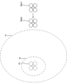
図5~図7は、図4に示した制御装置14の制御による移動体10の動作の一例を示す図である。図5~図7において、第1投影対象物6A及び第2投影対象物6Bは、人物1の周辺に位置しており、図1に示した投影対象物6と同様に、投影装置11によって投影画像が表示可能な投影面を有する物体である。図5~図7の例では、人物1は第2投影対象物6Bの方向を向いている。
図5~図7は、図4に示した制御装置14の制御による移動体10の動作の一例を示す図である。図5~図7において、第1投影対象物6A及び第2投影対象物6Bは、人物1の周辺に位置しており、図1に示した投影対象物6と同様に、投影装置11によって投影画像が表示可能な投影面を有する物体である。図5~図7の例では、人物1は第2投影対象物6Bの方向を向いている。
まず、図5に示す状態において、制御装置14は、撮像装置12による撮像結果から人物1を検知するとともに、人物1の状態を検出する。ここで、制御装置14は、移動体10(撮像装置12)と人物1との距離が遠いことに起因して、人物1が第2投影対象物6Bの方向を向いていることを検出できず、その結果、人物1からの観察に最適な投影対象位置を第1投影対象物6Aに決定したとする。また、制御装置14は、第1投影対象物6Aへの投影に最適な目標移動体位置を第1位置P1に決定したとする。この場合、制御装置14は、移動機構16を制御して、移動体10の第1位置P1への移動を開始する。
次に、制御装置14は、移動体10が第1位置P1へ到達するまでの間、撮像装置12による撮像結果から、最適な投影対象位置が変化したか否かを繰り返し判断する。そして、図6に示す状態において、制御装置14は、人物1が第2投影対象物6Bの方向を向いていることを検出し、その結果、人物1からの観察に最適な投影対象位置が第2投影対象物6Bであると判断したとする。この場合、制御装置14は、投影対象位置を第2投影対象物6Bに更新する。
また、制御装置14は、第2投影対象物6Bへの投影に最適な目標移動体位置を第2位置P2に決定したとする。この場合、制御装置14は、移動体10の移動先を第2位置P2に変更する。そして、移動体10が第2位置P2に到達すると、制御装置14は、図7に示すように、移動機構16を制御して、投影装置11から第2投影対象物6B(投影対象位置)へ画像の投影を開始させる。
このように、制御装置14は、人物1(第1対象)の状態の検出結果(第1対象情報)を取得し、その検出結果に基づいて投影対象位置及び目標移動体位置を決定し、目標移動体位置へ移動体10を移動させ、投影装置11から投影対象位置に投影させる。すなわち、制御装置14は、目標移動体位置へ移動体10が到達した状態で投影装置11から投影対象位置に投影させる。
そして、制御装置14は、移動体10が目標移動体位置に移動する途中においても、人物1の状態の検出結果(第2対象情報)を取得し、その検出結果に基づいて投影対象位置及び目標移動体位置を更新する。
したがって、最適と判断される投影対象位置や目標移動体位置が移動体10の移動中に変化した場合に、投影対象位置や目標移動体位置を柔軟に更新することができる。最適と判断される投影対象位置や目標移動体位置が移動体10の移動中に変化する場合には、例えば、遠くから判別できなかった状況が移動体10の移動中に判明して最適な投影対象位置が変化した場合や、移動体10の移動中に人物1や投影対象物の状態が変化した場合などが含まれる。
これにより、より良好な投影対象位置に対してより良好な目標移動体位置から投影を行って投影品質を向上させたり、最適な目標移動体位置まで短時間で移動して投影開始までにかかる時間を短縮したりすることができる。すなわち、より良好な投影を行うことができる。
人物1(第1対象)の状態の検出結果は、人物1を撮像装置12により撮像して得られた情報である。上記においては、撮像装置12による撮像結果から人物1の状態を検出する処理を制御装置14が行う例について説明したが、撮像装置12のプロセッサがこの処理を行う構成としてもよいし、撮像装置12や制御装置14と通信可能な他の装置がこの処理を行う構成としてもよい。
撮像装置12が移動体10に搭載されていることで、撮像装置12による撮像結果に基づく最適な投影対象位置が移動体10の移動中に変化しやすいが、本実施形態によれば、撮像装置12による撮像結果に基づいて最適と判断される投影対象位置や目標移動体位置が移動体10の移動中に変化した場合に、投影対象位置や目標移動体位置を柔軟に更新することができる。ただし、撮像装置12が移動体10に搭載されている構成に限らず、撮像装置12が制御装置14と通信可能であれば、撮像装置12が地上に設けられた構成であってもよいし、撮像装置12が移動体10とは異なる移動体(例えば飛翔体)に設けられた構成であってもよい。
<制御装置14による制御の第2の例>
図8は、制御装置14による制御の第2の例を示すフローチャートである。制御装置14は、図8に示す処理を実行してもよい。
図8は、制御装置14による制御の第2の例を示すフローチャートである。制御装置14は、図8に示す処理を実行してもよい。
図8に示すステップS31~S35は、図4に示したステップS11~S15と同様である。ステップS35の次に、制御装置14は、ステップS35によって取得した移動体10の位置に基づいて、移動体10が更新停止エリアに入ったか否かを判断する(ステップS36)。更新停止エリアは、目標移動体位置を含む所定領域である。更新停止エリアについては図9において説明する。
ステップS36において、移動体10が更新停止エリアに入っていない場合(ステップS36:No)は、制御装置14は、ステップS37へ移行する。ステップS37~S40は、図4に示したステップS17~S20と同様である。
ステップS36において、移動体10が更新停止エリアに入った場合(ステップS36:Yes)は、制御装置14は、ステップS35によって取得した移動体10の位置に基づいて、移動体10が目標移動体位置に到達したか否かを判断し(ステップS41)、移動体10が目標移動体位置に到達するまで待つ(ステップS41:Noのループ)。
ステップS41において、移動体10が目標移動体位置に到達した場合(ステップS41:Yes)は、制御装置14は、投影装置11から投影対象位置へ画像の投影を開始させる制御を行い(ステップS42)、一連の処理を終了する。
<図8に示した制御装置14の制御における更新停止エリア>
図9は、図8に示した制御装置14の制御における更新停止エリアの一例を示す図である。図9において、図5に示した部分と同様の部分については同一の符号を付して説明を省略する。図9の状態において、目標移動体位置は第1位置P1であるとする。制御装置14は、移動体10の目標移動体位置(第1位置P1)への移動中に、移動体10が更新停止エリアE1に入ると、投影対象位置及び目標移動体位置の更新を停止する。
図9は、図8に示した制御装置14の制御における更新停止エリアの一例を示す図である。図9において、図5に示した部分と同様の部分については同一の符号を付して説明を省略する。図9の状態において、目標移動体位置は第1位置P1であるとする。制御装置14は、移動体10の目標移動体位置(第1位置P1)への移動中に、移動体10が更新停止エリアE1に入ると、投影対象位置及び目標移動体位置の更新を停止する。
図9においては、更新停止エリアE1は、移動体10の移動方向における、目標移動体位置(第1位置P1)からの距離が所定距離以下の領域である。すなわち、制御装置14は、移動体10と目標移動体位置との間の距離が所定距離以下になると、投影対象位置及び目標移動体位置の更新を停止する。
これにより、移動体10が目標移動体位置に近づいた段階で投影対象位置や目標移動体位置が変更されることを回避し、移動体10の移動のふらつきを防止することができる。なお、更新停止エリアE1は、図9に示した例に限らず、目標移動体位置を中心とする球体領域であってもよいし、目標移動体位置を中心とする水平方向の円領域又は楕円であってもよいし、他の形状の領域であってもよい。また、更新停止エリアE1は、目標移動体位置からずれた位置(例えば移動体10の方向にずれた位置)を中心とする領域であってもよい。
<制御装置14による制御の第3の例>
図10は、制御装置14による制御の第3の例を示すフローチャートである。制御装置14は、図10に示す処理を実行してもよい。
図10は、制御装置14による制御の第3の例を示すフローチャートである。制御装置14は、図10に示す処理を実行してもよい。
図10に示すステップS51~S57は、図4に示したステップS11~S17と同様である。ステップS57の次に、制御装置14は、移動体10と目標移動体位置との距離に応じた更新可能エリアを算出する(ステップS58)。移動体10と目標移動体位置との距離に応じた更新可能エリアの算出については図11において説明する。
図10に示すステップS59~S62は、図4に示したステップS18~S21と同様である。ただし、ステップS59において、制御装置14は、投影が可能な投影候補位置のうち、ステップS58によって算出された更新可能エリアに含まれる投影候補位置の中から、人物1からの観察に最も適した投影候補位置を選択する。そして、制御装置14は、選択した投影候補位置が現在の投影対象位置から変化したか否かにより、最適な投影対象位置が変化したか否かを判断する。
<図10に示した制御装置14の制御における更新可能エリア>
図11は、図10に示した制御装置14の制御における更新可能エリアの一例を示す図である。図11は、移動体10を上空から垂直方向に見た様子を示している。図11の状態において、目標移動体位置は第1位置P1であるとする。
図11は、図10に示した制御装置14の制御における更新可能エリアの一例を示す図である。図11は、移動体10を上空から垂直方向に見た様子を示している。図11の状態において、目標移動体位置は第1位置P1であるとする。
第1更新可能エリアe1は、移動体10が第1位置p1に位置する時に算出される更新可能エリアである。第2更新可能エリアe2は、移動体10が第2位置p2に位置する時に算出される更新可能エリアである。第2位置p2は、第1位置p1より第1位置P1に近い位置である。
第1更新可能エリアe1及び第2更新可能エリアe2は、ともに第1位置P1(目標移動体位置)を含む領域であるが、第2更新可能エリアe2は第1更新可能エリアe1よりも狭い領域である。また、図11においては、第1更新可能エリアe1及び第2更新可能エリアe2は、ともに、水平方向の楕円領域である。
このように、制御装置14は、移動体10と目標移動体位置との距離が短いほど、更新可能エリアを狭くする。これにより、移動体10が目標移動体位置に近づくほど、投影対象位置や目標移動体位置の大幅な変更が抑制され、移動体10の移動のふらつきを防止することができる。なお、第1更新可能エリアe1及び第2更新可能エリアe2は、図11に示した例に限らず、各種の形状とすることができる。
また、第1更新可能エリアe1及び第2更新可能エリアe2は、目標移動体位置を中心とする領域であってもよいし、目標移動体位置からずれた位置(例えば移動体10の方向にずれた位置)を中心とする領域であってもよい。
<移動体10に非搭載の撮像装置>
図12は、移動体10に非搭載の撮像装置の一例を示す図である。例えば、制御装置14は、移動体10に非搭載の撮像装置12aと通信可能であってもよい。撮像装置12aは、例えば地上のうち投影対象物6の近くに設置されていてもよいし、移動体10とは異なる移動体(例えば別の飛翔体)に搭載されていてもよい。
図12は、移動体10に非搭載の撮像装置の一例を示す図である。例えば、制御装置14は、移動体10に非搭載の撮像装置12aと通信可能であってもよい。撮像装置12aは、例えば地上のうち投影対象物6の近くに設置されていてもよいし、移動体10とは異なる移動体(例えば別の飛翔体)に搭載されていてもよい。
この場合に、制御装置14は、撮像装置12aの撮像により得られた撮像画像を撮像装置12aから受信し、移動体10に搭載された撮像装置12による撮像結果と、撮像装置12aによる撮像結果と、の両方に基づいて、人物1(第1対象)の状態に関する第1対象情報を取得してもよい。
<人物1が移動体10を見ている状況>
図13は、人物1が移動体10を見ている状況の一例を示す図である。図13において、図5に示した部分と同様の部分については同一の符号を付して説明を省略する。図13に示す例では、人物1が、飛翔中の移動体10に気付き、移動体10を見上げている。制御装置14は、例えば撮像装置12による撮像結果に基づいて、人物1が移動体10を見ている状態を検知する。例えば、制御装置14は、撮像装置12により得られた撮像画像に基づく画像認識処理により人物1の顔の向きや視線の向きを検出することで、人物1が移動体10を見ている状態を検知する。
図13は、人物1が移動体10を見ている状況の一例を示す図である。図13において、図5に示した部分と同様の部分については同一の符号を付して説明を省略する。図13に示す例では、人物1が、飛翔中の移動体10に気付き、移動体10を見上げている。制御装置14は、例えば撮像装置12による撮像結果に基づいて、人物1が移動体10を見ている状態を検知する。例えば、制御装置14は、撮像装置12により得られた撮像画像に基づく画像認識処理により人物1の顔の向きや視線の向きを検出することで、人物1が移動体10を見ている状態を検知する。
制御装置14は、人物1が移動体10を見ている状態を検知すると、その状態で検出した人物1の状態を除外して、投影対象位置の決定や更新を行う。例えば、制御装置14は、人物1が移動体10を見ている状態を検知すると、人物1が移動体10を見ている状態を検知する直前に検出した人物1の状態が継続していると見なして、投影対象位置の決定や更新を行う。
このように、制御装置14は、移動体10に起因する人物1の状態の検出結果(第1対象情報)の変化を除外して投影対象位置を決定してもよい。これにより、より適切な投影対象位置や目標移動体位置を精度よく選択することが可能になる。
<制御装置14による制御の第4の例>
図14は、制御装置14による制御の第4の例を示すフローチャートである。制御装置14は、図14に示す処理を実行してもよい。
図14は、制御装置14による制御の第4の例を示すフローチャートである。制御装置14は、図14に示す処理を実行してもよい。
図14に示すステップS71~S81は、図4に示したステップS11~S21と同様である。ただし、ステップS81によって投影装置11から投影対象位置へ画像の投影を開始させる制御を行った後、制御装置14は、ステップS77へ移行する。
すなわち、制御装置14は、移動体10が目標移動体位置に到達し、投影装置11から投影対象位置へ画像の投影を開始させた後も、撮像装置12による撮像結果に基づく人物1の状態(第2対象情報)の取得と、取得した人物1の状態に基づく投影対象位置及び目標移動体位置の更新を継続する。そして、目標移動体位置を更新した場合は、移動体10が目標移動体位置に到達していない状態となるため、更新した目標移動体位置への移動体10の移動が再度行われることになる。
これにより、移動体10が目標移動体位置に到達し、投影装置11から投影対象位置へ画像の投影を開始させた後に、最適と判断される投影対象位置や目標移動体位置が変化した場合に、投影対象位置や目標移動体位置を柔軟に更新することができる。
<制御装置14による制御の第5の例>
図15は、制御装置14による制御の第5の例を示すフローチャートである。制御装置14は、図15に示す処理を実行してもよい。
図15は、制御装置14による制御の第5の例を示すフローチャートである。制御装置14は、図15に示す処理を実行してもよい。
図15に示すステップS91~S99は、図4に示したステップS11~S19と同様である。ステップS99の次に、制御装置14は、ステップS35によって取得した移動体10の位置に基づいて、移動体10が移動体位置更新停止エリアに入ったか否かを判断する(ステップS100)。移動体位置更新停止エリアは、図8,図9において説明した更新停止エリアと同様の領域である。ただし、移動体位置更新停止エリアは、目標移動体位置の更新は停止される一方、投影対象位置の更新は停止されない領域である。
ステップS100において、移動体10が移動体位置更新停止エリアに入っていない場合(ステップS100:No)は、制御装置14は、ステップS101へ移行して目標移動体位置を更新する。図15に示すステップS101,S102は、図4に示したステップS20,S21と同様である。移動体10が移動体位置更新停止エリアに入った場合(ステップS100:Yes)は、制御装置14は、目標移動体位置を維持してステップS95へ戻る。
このように、制御装置14は、移動体10が目標移動体位置を含む移動体位置更新停止エリア(所定領域)内に位置しかつ投影対象位置を更新する場合は、目標移動体位置を維持するようにしてもよい。これにより、移動体10が目標移動体位置にある程度近づいた段階で最適な目標移動体位置が変化した場合は、目標移動体位置は維持して投影方向だけ変えることで投影対象位置を変更することができる。これにより、投影対象位置の更新に伴って移動体10の移動時間が長くなり、投影の開始までにかかる時間が長くなることを抑制することができる。
<第1対象が複数人の人物である場合>
第1対象が人物1である場合について説明したが、第1対象は複数の人物であってもよい。例えば、制御装置14は、撮像装置12による撮像結果から複数人の人物を検知した場合、その複数人の人物の状態を示す第1対象情報を取得し、取得した第1対象情報に基づいて投影対象位置や目標移動体位置を決定する。この場合の第1対象情報は、例えば、複数の人物の目の位置(視線の向き)、複数の人物の体の向き、複数の人物の位置関係、複数の人物の移動状態の少なくともいずれかである。
第1対象が人物1である場合について説明したが、第1対象は複数の人物であってもよい。例えば、制御装置14は、撮像装置12による撮像結果から複数人の人物を検知した場合、その複数人の人物の状態を示す第1対象情報を取得し、取得した第1対象情報に基づいて投影対象位置や目標移動体位置を決定する。この場合の第1対象情報は、例えば、複数の人物の目の位置(視線の向き)、複数の人物の体の向き、複数の人物の位置関係、複数の人物の移動状態の少なくともいずれかである。
例えば、制御装置14は、投影が可能な投影候補位置のそれぞれについて、複数の人物からの観察のしやすさの評価値を算出し、算出した評価値が最も高い投影候補位置を投影対象位置として決定する。例えば、複数の人物が第1人物及び第2人物の2人であるとすると、複数の人物からの観察のしやすさの評価値は、第1人物からの観察のしやすさの評価値と、第2人物からの観察のしやすさの評価値と、の代表値(例えば合計、平均、最小値など)とすることができる。平均は重み付け平均であってもよい。
<第1対象が自動車等である場合>
第1対象が人物1である場合について説明したが、第1対象は人物以外であってもよい。例えば、第1対象は、人物が乗車した自動車などであってもよい。例えば、自動車に乗車した人物がフロントガラス越しに投影画像を観察する場合、自動車の前方が向いている方向にある投影対象物が、最適な投影対象位置となる可能性が高い。この場合、制御装置14は、自動車(第1対象)の状態の検出結果として、例えば自動車の向きの検出結果などを取得する。
第1対象が人物1である場合について説明したが、第1対象は人物以外であってもよい。例えば、第1対象は、人物が乗車した自動車などであってもよい。例えば、自動車に乗車した人物がフロントガラス越しに投影画像を観察する場合、自動車の前方が向いている方向にある投影対象物が、最適な投影対象位置となる可能性が高い。この場合、制御装置14は、自動車(第1対象)の状態の検出結果として、例えば自動車の向きの検出結果などを取得する。
<第1対象が被投影物である場合>
第1対象は、投影の観察者や、投影の観察者が登場した自動車等に限らず、投影対象位置の候補となる被投影物であってもよい。例えば、制御装置14は、第1対象情報として、被投影物の投影面の状態(投影に適した面を有するか否か等)に関する投影面情報を取得してもよい。
第1対象は、投影の観察者や、投影の観察者が登場した自動車等に限らず、投影対象位置の候補となる被投影物であってもよい。例えば、制御装置14は、第1対象情報として、被投影物の投影面の状態(投影に適した面を有するか否か等)に関する投影面情報を取得してもよい。
この場合、制御装置14は、被投影物(第1対象)の状態の検出結果(第1対象情報)を取得し、その検出結果に基づいて投影対象位置及び目標移動体位置を決定し、目標移動体位置へ移動体10を移動させ、投影装置11から投影対象位置に投影させる。そして、制御装置14は、移動体10が目標移動体位置に移動する途中においても、被投影物の状態の検出結果(第2対象情報)を取得し、その検出結果に基づいて投影対象位置及び目標移動体位置を更新する。
したがって、最適と判断される投影対象位置や目標移動体位置が移動体10の移動中に変化した場合に、投影対象位置や目標移動体位置を柔軟に更新することができる。最適と判断される投影対象位置や目標移動体位置が移動体10の移動中に変化する場合には、例えば、遠くから判別できなかった状況(例えば投影面の状態)が移動体10の移動中に判明して最適な投影対象位置が変化した場合や、移動体10の移動中に被投影物の状態が変化した場合などが含まれる。
これにより、より良好な投影対象位置に対してより良好な目標移動体位置から投影を行って投影品質を向上させたり、最適な目標移動体位置まで短時間で移動して投影開始までにかかる時間を短縮したりすることができる。すなわち、より良好な投影を行うことができる。
<第1対象が人物等及び被投影物である場合>
また、第1対象は、人物(又は人物が乗車した自動車等)と、投影対象位置の候補となる被投影物と、の両方を含んでもよい。この場合、制御装置14は、例えば人物及び被投影物(第1対象)の状態の検出結果(第1対象情報)を取得し、その検出結果に基づいて投影対象位置及び目標移動体位置を決定し、目標移動体位置へ移動体10を移動させ、投影装置11から投影対象位置に投影させる。そして、制御装置14は、移動体10が目標移動体位置に移動する途中においても、人物及び被投影物の状態の検出結果(第2対象情報)を取得し、その検出結果に基づいて投影対象位置及び目標移動体位置を更新する。
また、第1対象は、人物(又は人物が乗車した自動車等)と、投影対象位置の候補となる被投影物と、の両方を含んでもよい。この場合、制御装置14は、例えば人物及び被投影物(第1対象)の状態の検出結果(第1対象情報)を取得し、その検出結果に基づいて投影対象位置及び目標移動体位置を決定し、目標移動体位置へ移動体10を移動させ、投影装置11から投影対象位置に投影させる。そして、制御装置14は、移動体10が目標移動体位置に移動する途中においても、人物及び被投影物の状態の検出結果(第2対象情報)を取得し、その検出結果に基づいて投影対象位置及び目標移動体位置を更新する。
<投影対象位置の決定方法>
制御装置14は、第1対象の状態(第1対象情報)に基づく投影対象位置の決定方法を、移動体10と目標移動体位置との距離に基づいて変更してもよい。一例としては、制御装置14は、撮像装置12による撮像結果から検出した人物1の位置と、撮像装置12による撮像結果から検出した人物1の向きと、に基づいて投影対象位置を決定する。
制御装置14は、第1対象の状態(第1対象情報)に基づく投影対象位置の決定方法を、移動体10と目標移動体位置との距離に基づいて変更してもよい。一例としては、制御装置14は、撮像装置12による撮像結果から検出した人物1の位置と、撮像装置12による撮像結果から検出した人物1の向きと、に基づいて投影対象位置を決定する。
具体的には、制御装置14は、投影が可能な投影候補位置のそれぞれについて、検出した人物1の位置から算出した観察のしやすさの第1評価値と、検出した人物1の向きから算出した観察のしやすさの第2評価値と、に基づいて、α×第1評価値+β×第2評価値によって総合評価値を算出し、算出した総合評価値が最も高い投影候補位置を投影対象位置として決定する。
この場合に、制御装置14は、例えば、移動体10と目標移動体位置との距離が所定距離以上の場合にα>βとなる係数α,βを設定して上記の総合評価値を算出し、移動体10と目標移動体位置との距離が所定距離未満の場合にα<βとなる係数α,βを設定して上記の総合評価値を算出する。又は、制御装置14は、移動体10と目標移動体位置との距離が所定距離以上の場合にβに第1の値を設定して上記の総合評価値を算出し、移動体10と目標移動体位置との距離が所定距離未満の場合にβに第2の値を設定して上記の総合評価値を算出してもよい。第1の値<第2の値である。
これにより、移動体10と目標移動体位置が遠い段階では人物1の向きよりも人物1の位置を重視して投影対象位置を決定し、移動体10と目標移動体位置が近くなった段階では人物1の位置よりも人物1の向きを重視して投影対象位置を決定することができる。すなわち、移動体10と目標移動体位置が遠く人物1の向き等の詳細な状況が判別しにくい段階では人物1の位置を重視して投影対象位置を決定し、移動体10を人物1へ近づくように移動させることができる。そして、移動体10と目標移動体位置が近くなり人物1の向き等の詳細な状況が判別しやすい段階で人物1の向きを考慮して投影対象位置を決定し、より人物1が観察しやすい投影対象位置を決定することができる。
<外部からの指示情報に基づく投影対象位置及び目標移動体位置の更新>
移動体10に搭載された制御装置14によって投影対象位置や目標移動体位置を決定する構成について説明したが、この構成において、制御装置14は、移動体10が目標移動体位置に移動する途中において、移動体10の外部の装置から、投影対象位置及び目標移動体位置の少なくともいずれかを指示する指示情報を受信した場合、その指示情報に基づいて投影対象位置や目標移動体位置を更新するようにしてもよい。
移動体10に搭載された制御装置14によって投影対象位置や目標移動体位置を決定する構成について説明したが、この構成において、制御装置14は、移動体10が目標移動体位置に移動する途中において、移動体10の外部の装置から、投影対象位置及び目標移動体位置の少なくともいずれかを指示する指示情報を受信した場合、その指示情報に基づいて投影対象位置や目標移動体位置を更新するようにしてもよい。
<移動体10の変形例>
移動体10がマルチコプターである構成について説明したが、移動体10はマルチコプター以外の航空機(飛翔体)であってもよい。また、移動体10は、飛翔体に限らず、地上を走行或いは歩行する車両やロボット等であってもよい。
移動体10がマルチコプターである構成について説明したが、移動体10はマルチコプター以外の航空機(飛翔体)であってもよい。また、移動体10は、飛翔体に限らず、地上を走行或いは歩行する車両やロボット等であってもよい。
<更新対象の変形例>
制御装置14が投影対象位置及び目標移動体位置を更新する構成について説明したが、制御装置14は投影対象位置及び目標移動体位置のいずれかを更新する構成としてもよい。例えば、制御装置14は、移動体10が目標移動体位置に移動する途中において、人物1の状態の検出結果(第2対象情報)を取得し、その検出結果に基づいて投影対象位置を更新する。これにより、最適と判断される投影対象位置が移動体10の移動中に変化した場合に、投影対象位置を柔軟に更新することができる。したがって、より良好な投影対象位置に対して投影を行って投影品質を向上させることができる。すなわち、より良好な投影を行うことができる。
制御装置14が投影対象位置及び目標移動体位置を更新する構成について説明したが、制御装置14は投影対象位置及び目標移動体位置のいずれかを更新する構成としてもよい。例えば、制御装置14は、移動体10が目標移動体位置に移動する途中において、人物1の状態の検出結果(第2対象情報)を取得し、その検出結果に基づいて投影対象位置を更新する。これにより、最適と判断される投影対象位置が移動体10の移動中に変化した場合に、投影対象位置を柔軟に更新することができる。したがって、より良好な投影対象位置に対して投影を行って投影品質を向上させることができる。すなわち、より良好な投影を行うことができる。
又は、制御装置14は、移動体10が目標移動体位置に移動する途中において、人物1の状態の検出結果(第2対象情報)を取得し、その検出結果に基づいて目標移動体位置を更新する。これにより、最適と判断される目標移動体位置が移動体10の移動中に変化した場合に、目標移動体位置を柔軟に更新することができる。したがって、より良好な目標移動体位置から投影を行って投影品質を向上させることができる。すなわち、より良好な投影を行うことができる。
<制御装置の他の適用例>
本発明の制御装置を移動体10の制御装置14に適用する場合について説明したが、このような構成に限らない。
本発明の制御装置を移動体10の制御装置14に適用する場合について説明したが、このような構成に限らない。
図16は、本発明の制御装置を適用した情報端末110の一例を示す図である。本発明の制御装置は、情報端末110に適用されてもよい。
情報端末110は、移動体10と直接又は間接的に通信可能な情報端末である。情報端末110と移動体10との間の通信は、例えば無線通信である。情報端末110は、移動体10と通信を行うことにより、上記の制御装置14による各種の制御を実行する。図16の例では、情報端末110は、運用者2に携帯されたスマートフォンである。ただし、情報端末110は、デスクトップ型のパーソナルコンピュータ、ノート型のパーソナルコンピュータ、タブレット端末など各種の情報端末とすることができる。
例えば、情報端末110は、撮像装置12による撮像画像を移動体10から受信し、受信した撮像画像に基づく画像認識処理によって、人物1(第1対象)の状態の検出結果(第1対象情報)を取得し、その検出結果に基づいて投影対象位置及び目標移動体位置を決定する。そして、情報端末110は、移動体10と通信を行うことにより、目標移動体位置へ移動体10を移動させ、投影装置11から投影対象位置に投影させる制御を行う。
また、情報端末110は、移動体10が目標移動体位置に移動する途中においても、移動体10から受信した撮像画像に基づいて人物1の状態の検出結果(第2対象情報)を取得し、その検出結果に基づいて投影対象位置及び目標移動体位置を更新する。そして、情報端末110は、移動体10と通信を行うことにより、更新した投影対象位置及び目標移動体位置を移動体10に設定する。これにより、本発明の制御装置を移動体10に適用した構成と同様に、より良好な投影を行うことができる。
なお、撮像装置12による撮像画像に基づく画像認識処理による人物1の状態の検出結果の取得を移動体10において行い、情報端末110は、その検出結果を移動体10から受信する構成としてもよい。
<情報端末110のハードウェア構成>
図17は、情報端末110のハードウェア構成の一例を示す図である。図16に示した情報端末110は、例えば図17に示す情報端末110により実現することができる。情報端末110は、プロセッサ111と、メモリ112と、無線通信インタフェース113と、ユーザインタフェース114と、を備える。プロセッサ111、メモリ112、無線通信インタフェース113、及びユーザインタフェース114は、例えばバス119によって接続される。
図17は、情報端末110のハードウェア構成の一例を示す図である。図16に示した情報端末110は、例えば図17に示す情報端末110により実現することができる。情報端末110は、プロセッサ111と、メモリ112と、無線通信インタフェース113と、ユーザインタフェース114と、を備える。プロセッサ111、メモリ112、無線通信インタフェース113、及びユーザインタフェース114は、例えばバス119によって接続される。
プロセッサ111は、信号処理を行う回路であり、例えば情報端末110の全体の制御を司るCPUである。なお、プロセッサ111は、FPGAやDSP(Digital Signal Processor)などの他のデジタル回路により実現されてもよい。また、プロセッサ111は、複数のデジタル回路を組み合わせて実現されてもよい。
メモリ112には、例えばメインメモリ及び補助メモリが含まれる。メインメモリは、例えばRAM(Random Access Memory)である。メインメモリは、プロセッサ111のワークエリアとして使用される。
補助メモリは、例えば磁気ディスク、光ディスク、フラッシュメモリなどの不揮発性メモリである。補助メモリには、情報端末110を動作させる各種のプログラムが記憶されている。補助メモリに記憶されたプログラムは、メインメモリにロードされてプロセッサ111によって実行される。
また、補助メモリは、情報端末110から取り外し可能な可搬型のメモリを含んでもよい。可搬型のメモリには、USB(Universal Serial Bus)フラッシュドライブやSD(Secure Digital)メモリカードなどのメモリカードや、外付けハードディスクドライブなどがある。
無線通信インタフェース113は、情報端末110の外部(例えば移動体10)との間で無線通信を行う通信インタフェースである。無線通信インタフェース113は、プロセッサ111によって制御される。
ユーザインタフェース114は、例えば、ユーザからの操作入力を受け付ける入力デバイスや、ユーザへ情報を出力する出力デバイスなどを含む。入力デバイスは、例えばポインティングデバイス(例えばマウス)、キー(例えばキーボード)やリモコンなどにより実現することができる。出力デバイスは、例えばディスプレイやスピーカなどにより実現することができる。また、タッチパネルなどによって入力デバイス及び出力デバイスを実現してもよい。ユーザインタフェース114は、プロセッサ111によって制御される。
<対象情報の信頼度に基づく処理>
制御装置14は、取得した第1対象の状態を示す対象情報(第1対象情報又は第2対象情報)の信頼度を算出し、信頼度が低い対象情報については除外して、投影対象位置や目標移動体位置の更新を行ってもよい。例えば、制御装置14は、取得した対象情報の信頼度が閾値未満である場合は、信頼度が閾値以上である直近の対象情報に基づく投影対象位置や目標移動体位置を維持する。
制御装置14は、取得した第1対象の状態を示す対象情報(第1対象情報又は第2対象情報)の信頼度を算出し、信頼度が低い対象情報については除外して、投影対象位置や目標移動体位置の更新を行ってもよい。例えば、制御装置14は、取得した対象情報の信頼度が閾値未満である場合は、信頼度が閾値以上である直近の対象情報に基づく投影対象位置や目標移動体位置を維持する。
<複数のパラメータに基づく投影対象位置等の更新>
第1対象が人物である場合、人物1の目の位置(視線の向き)や人物1の体の向きなどを対象情報として取得する場合について説明したが、この場合に、制御装置14は、人物1の視線が変化しても、人物1の位置や人物1の体の向きが変化していない場合は、投影対象位置や目標移動体位置の更新を行わないようにしてもよい。すなわち、人物1の位置、人物1の目の位置、人物1の体の向き、人物1の移動状態(速度や方向)、及び人物1の人数などの複数のパラメータが対象情報に含まれる場合、制御装置14は、複数のパラメータの組み合わせに基づいて投影対象位置や目標移動体位置の更新を行うようにしてもよい。
第1対象が人物である場合、人物1の目の位置(視線の向き)や人物1の体の向きなどを対象情報として取得する場合について説明したが、この場合に、制御装置14は、人物1の視線が変化しても、人物1の位置や人物1の体の向きが変化していない場合は、投影対象位置や目標移動体位置の更新を行わないようにしてもよい。すなわち、人物1の位置、人物1の目の位置、人物1の体の向き、人物1の移動状態(速度や方向)、及び人物1の人数などの複数のパラメータが対象情報に含まれる場合、制御装置14は、複数のパラメータの組み合わせに基づいて投影対象位置や目標移動体位置の更新を行うようにしてもよい。
<他の投影装置の投影との干渉を考慮した投影対象位置等の更新>
第1対象は、移動体10に搭載された投影装置11とは異なる他の投影装置を含んでもよい。この場合、制御装置14は、他の投影装置の投影状態を検出し、他の投影装置の投影との干渉を考慮して、投影装置11による投影に適した投影対象位置や目標移動体位置の決定及び更新を行ってもよい。
第1対象は、移動体10に搭載された投影装置11とは異なる他の投影装置を含んでもよい。この場合、制御装置14は、他の投影装置の投影状態を検出し、他の投影装置の投影との干渉を考慮して、投影装置11による投影に適した投影対象位置や目標移動体位置の決定及び更新を行ってもよい。
<第1対象情報及び第2対象情報の差分に基づく投影対象位置等の更新>
制御装置14は、最初に投影対象位置及び目標移動体位置を決定するために用いた第1対象情報と、目標移動体位置への移動体10の移動を開始した後に取得した第2対象情報と、の差分に基づいて、投影対象位置や目標移動体位置の更新を行うようにしてもよい。例えば、制御装置14は、第1対象情報と第2対象情報との差分が所定の条件を満たさない場合は、投影対象位置や目標移動体位置の更新を行わないようにしてもよい。
制御装置14は、最初に投影対象位置及び目標移動体位置を決定するために用いた第1対象情報と、目標移動体位置への移動体10の移動を開始した後に取得した第2対象情報と、の差分に基づいて、投影対象位置や目標移動体位置の更新を行うようにしてもよい。例えば、制御装置14は、第1対象情報と第2対象情報との差分が所定の条件を満たさない場合は、投影対象位置や目標移動体位置の更新を行わないようにしてもよい。
所定の条件とは、例えば、第1対象情報が示す第1対象の状態と、第2対象情報が示す第1対象の状態と、の差分が所定値以上であるという条件である。第1対象が人物1である場合、第1対象の状態とは、例えば、人物1の位置、人物1の目の位置、人物1の体の向き、人物1の移動状態(速度や方向)、及び人物1の人数の少なくともいずれかである。
<外部からの移動中止の指示に基づく制御>
制御装置14は、移動体10が目標移動体位置に移動する途中において、移動体10の外部の装置から、移動体10の移動中止を指示する指示情報を受信した場合、その指示情報に基づいて移動体10の移動を中止するようにしてもよい。
制御装置14は、移動体10が目標移動体位置に移動する途中において、移動体10の外部の装置から、移動体10の移動中止を指示する指示情報を受信した場合、その指示情報に基づいて移動体10の移動を中止するようにしてもよい。
本明細書には少なくとも以下の事項が記載されている。
(1)
プロセッサを備え、投影装置を搭載した移動体を制御する制御装置であって、
上記プロセッサは、
第1対象の状態に関する第1対象情報を取得し、
上記第1対象情報に基づいて投影対象位置及び目標移動体位置を決定し、
上記目標移動体位置へ上記移動体を移動させ、
上記投影装置から上記投影対象位置に投影させ、
上記移動体が上記目標移動体位置に移動する途中において、上記第1対象の状態に関する第2対象情報を取得し、上記第2対象情報に基づいて上記投影対象位置及び/又は上記目標移動体位置を更新する、
制御装置。
プロセッサを備え、投影装置を搭載した移動体を制御する制御装置であって、
上記プロセッサは、
第1対象の状態に関する第1対象情報を取得し、
上記第1対象情報に基づいて投影対象位置及び目標移動体位置を決定し、
上記目標移動体位置へ上記移動体を移動させ、
上記投影装置から上記投影対象位置に投影させ、
上記移動体が上記目標移動体位置に移動する途中において、上記第1対象の状態に関する第2対象情報を取得し、上記第2対象情報に基づいて上記投影対象位置及び/又は上記目標移動体位置を更新する、
制御装置。
(2)
(1)に記載の制御装置であって、
上記第1対象情報は、上記第1対象を撮像装置により撮像して得られた情報である、
制御装置。
(1)に記載の制御装置であって、
上記第1対象情報は、上記第1対象を撮像装置により撮像して得られた情報である、
制御装置。
(3)
(2)に記載の制御装置であって、
上記撮像装置は、上記移動体に搭載されている、
制御装置。
(2)に記載の制御装置であって、
上記撮像装置は、上記移動体に搭載されている、
制御装置。
(4)
(3)に記載の制御装置であって、
上記撮像装置は、上記移動体に搭載された第1撮像装置と、上記移動体に非搭載の第2撮像装置と、を含む、
制御装置。
(3)に記載の制御装置であって、
上記撮像装置は、上記移動体に搭載された第1撮像装置と、上記移動体に非搭載の第2撮像装置と、を含む、
制御装置。
(5)
(1)から(4)のいずれか1項に記載の制御装置であって、
上記第1対象は人物を含み、
上記第1対象情報は、上記人物の目の位置、上記人物の体の向き、上記人物の移動状態、及び上記人物の人数の少なくともいずれかを示す、
制御装置。
(1)から(4)のいずれか1項に記載の制御装置であって、
上記第1対象は人物を含み、
上記第1対象情報は、上記人物の目の位置、上記人物の体の向き、上記人物の移動状態、及び上記人物の人数の少なくともいずれかを示す、
制御装置。
(6)
(5)に記載の制御装置であって、
上記プロセッサは、上記第1対象情報として複数の人物の情報を取得した場合、上記複数の人物の目の位置、上記複数の人物の体の向き、上記複数の人物の位置関係、上記複数の人物の移動状態の少なくともいずれかに基づいて上記投影対象位置を決定する、
制御装置。
(5)に記載の制御装置であって、
上記プロセッサは、上記第1対象情報として複数の人物の情報を取得した場合、上記複数の人物の目の位置、上記複数の人物の体の向き、上記複数の人物の位置関係、上記複数の人物の移動状態の少なくともいずれかに基づいて上記投影対象位置を決定する、
制御装置。
(7)
(1)から(6)のいずれか1項に記載の制御装置であって、
上記第1対象は、上記投影対象位置の候補となる被投影物を含む、
制御装置。
(1)から(6)のいずれか1項に記載の制御装置であって、
上記第1対象は、上記投影対象位置の候補となる被投影物を含む、
制御装置。
(8)
(7)に記載の制御装置であって、
上記第1対象情報は、上記被投影物の投影面の状態に関する投影面情報を含む、
制御装置。
(7)に記載の制御装置であって、
上記第1対象情報は、上記被投影物の投影面の状態に関する投影面情報を含む、
制御装置。
(9)
(1)から(8)のいずれか1項に記載の制御装置であって、
上記プロセッサは、上記移動体が上記目標移動体位置を含む所定領域に入った場合に上記投影対象位置及び/又は上記目標移動体位置の更新を停止する、
制御装置。
(1)から(8)のいずれか1項に記載の制御装置であって、
上記プロセッサは、上記移動体が上記目標移動体位置を含む所定領域に入った場合に上記投影対象位置及び/又は上記目標移動体位置の更新を停止する、
制御装置。
(10)
(1)から(9)のいずれか1項に記載の制御装置であって、
上記プロセッサは、上記移動体と上記目標移動体位置との距離に応じた範囲内で上記投影対象位置及び/又は上記目標移動体位置を更新する、
制御装置。
(1)から(9)のいずれか1項に記載の制御装置であって、
上記プロセッサは、上記移動体と上記目標移動体位置との距離に応じた範囲内で上記投影対象位置及び/又は上記目標移動体位置を更新する、
制御装置。
(11)
(1)から(10)のいずれか1項に記載の制御装置であって、
上記プロセッサは、
上記第1対象情報に基づく上記投影対象位置の決定方法を、上記移動体と上記目標移動体位置との距離に基づいて変更する、
制御装置。
(1)から(10)のいずれか1項に記載の制御装置であって、
上記プロセッサは、
上記第1対象情報に基づく上記投影対象位置の決定方法を、上記移動体と上記目標移動体位置との距離に基づいて変更する、
制御装置。
(12)
(1)から(11)のいずれか1項に記載の制御装置であって、
上記プロセッサは、上記移動体に起因する上記第1対象情報の変化を除外して上記投影対象位置を決定する、
制御装置。
(1)から(11)のいずれか1項に記載の制御装置であって、
上記プロセッサは、上記移動体に起因する上記第1対象情報の変化を除外して上記投影対象位置を決定する、
制御装置。
(13)
(1)から(12)のいずれか1項に記載の制御装置であって、
上記プロセッサは、上記移動体が上記目標移動体位置に移動した後において、上記第2対象情報を取得し、上記第2対象情報に基づいて上記投影対象位置及び/又は上記目標移動体位置を更新する、
制御装置。
(1)から(12)のいずれか1項に記載の制御装置であって、
上記プロセッサは、上記移動体が上記目標移動体位置に移動した後において、上記第2対象情報を取得し、上記第2対象情報に基づいて上記投影対象位置及び/又は上記目標移動体位置を更新する、
制御装置。
(14)
(1)から(13)のいずれか1項に記載の制御装置であって、
上記プロセッサは、上記移動体が上記目標移動体位置を含む所定領域内に位置しかつ上記投影対象位置を更新する場合は上記目標移動体位置を維持する、
制御装置。
(1)から(13)のいずれか1項に記載の制御装置であって、
上記プロセッサは、上記移動体が上記目標移動体位置を含む所定領域内に位置しかつ上記投影対象位置を更新する場合は上記目標移動体位置を維持する、
制御装置。
(15)
(1)から(14)のいずれか1項に記載の制御装置であって、
上記プロセッサは、上記投影対象位置及び目標移動体位置の少なくともいずれかを指示する指示情報を受信した場合、上記指示情報に基づいて上記投影対象位置及び/又は上記目標移動体位置を更新する、
制御装置。
(1)から(14)のいずれか1項に記載の制御装置であって、
上記プロセッサは、上記投影対象位置及び目標移動体位置の少なくともいずれかを指示する指示情報を受信した場合、上記指示情報に基づいて上記投影対象位置及び/又は上記目標移動体位置を更新する、
制御装置。
(16)
投影装置を搭載した移動体を制御する制御装置のプロセッサが、
第1対象の状態に関する第1対象情報を取得し、
上記第1対象情報に基づいて投影対象位置及び目標移動体位置を決定し、
上記目標移動体位置へ上記移動体を移動させ、
上記投影装置から上記投影対象位置に投影させ、
上記移動体が上記目標移動体位置に移動する途中において、上記第1対象の状態に関する第2対象情報を取得し、上記第2対象情報に基づいて上記投影対象位置及び/又は上記目標移動体位置を更新する、
制御方法。
投影装置を搭載した移動体を制御する制御装置のプロセッサが、
第1対象の状態に関する第1対象情報を取得し、
上記第1対象情報に基づいて投影対象位置及び目標移動体位置を決定し、
上記目標移動体位置へ上記移動体を移動させ、
上記投影装置から上記投影対象位置に投影させ、
上記移動体が上記目標移動体位置に移動する途中において、上記第1対象の状態に関する第2対象情報を取得し、上記第2対象情報に基づいて上記投影対象位置及び/又は上記目標移動体位置を更新する、
制御方法。
(17)
投影装置を搭載した移動体を制御する制御装置のプロセッサに、
第1対象の状態に関する第1対象情報を取得し、
上記第1対象情報に基づいて投影対象位置及び目標移動体位置を決定し、
上記目標移動体位置へ上記移動体を移動させ、
上記投影装置から上記投影対象位置に投影させ、
上記移動体が上記目標移動体位置に移動する途中において、上記第1対象の状態に関する第2対象情報を取得し、上記第2対象情報に基づいて上記投影対象位置及び/又は上記目標移動体位置を更新する、
処理を実行させるための制御プログラム。
投影装置を搭載した移動体を制御する制御装置のプロセッサに、
第1対象の状態に関する第1対象情報を取得し、
上記第1対象情報に基づいて投影対象位置及び目標移動体位置を決定し、
上記目標移動体位置へ上記移動体を移動させ、
上記投影装置から上記投影対象位置に投影させ、
上記移動体が上記目標移動体位置に移動する途中において、上記第1対象の状態に関する第2対象情報を取得し、上記第2対象情報に基づいて上記投影対象位置及び/又は上記目標移動体位置を更新する、
処理を実行させるための制御プログラム。
以上、各種の実施の形態について説明したが、本発明はかかる例に限定されないことは言うまでもない。当業者であれば、特許請求の範囲に記載された範疇内において、各種の変更例又は修正例に想到し得ることは明らかであり、それらについても当然に本発明の技術的範囲に属するものと了解される。また、発明の趣旨を逸脱しない範囲において、上記実施の形態における各構成要素を任意に組み合わせてもよい。
なお、本出願は、2021年12月27日出願の日本特許出願(特願2021-212601)に基づくものであり、その内容は本出願の中に参照として援用される。
1 人物
2 運用者
6 投影対象物
6A 第1投影対象物
6B 第2投影対象物
7 被投影領域
10 移動体
11 投影装置
12,12a 撮像装置
14 制御装置
14a 記憶媒体
15 通信部
16 移動機構
31 光源
32 光変調部
33 投影光学系
34 制御回路
110 情報端末
111 プロセッサ
112 メモリ
113 無線通信インタフェース
114 ユーザインタフェース
119 バス
e1 第1更新可能エリア
p1 第1位置
e2 第2更新可能エリア
p2 第2位置
P1 第1位置
E1 更新停止エリア
P2 第2位置
2 運用者
6 投影対象物
6A 第1投影対象物
6B 第2投影対象物
7 被投影領域
10 移動体
11 投影装置
12,12a 撮像装置
14 制御装置
14a 記憶媒体
15 通信部
16 移動機構
31 光源
32 光変調部
33 投影光学系
34 制御回路
110 情報端末
111 プロセッサ
112 メモリ
113 無線通信インタフェース
114 ユーザインタフェース
119 バス
e1 第1更新可能エリア
p1 第1位置
e2 第2更新可能エリア
p2 第2位置
P1 第1位置
E1 更新停止エリア
P2 第2位置
Claims (17)
- プロセッサを備え、投影装置を搭載した移動体を制御する制御装置であって、
前記プロセッサは、
第1対象の状態に関する第1対象情報を取得し、
前記第1対象情報に基づいて投影対象位置及び目標移動体位置を決定し、
前記目標移動体位置へ前記移動体を移動させ、
前記投影装置から前記投影対象位置に投影させ、
前記移動体が前記目標移動体位置に移動する途中において、前記第1対象の状態に関する第2対象情報を取得し、前記第2対象情報に基づいて前記投影対象位置及び/又は前記目標移動体位置を更新する、
制御装置。 - 請求項1に記載の制御装置であって、
前記第1対象情報は、前記第1対象を撮像装置により撮像して得られた情報である、
制御装置。 - 請求項2に記載の制御装置であって、
前記撮像装置は、前記移動体に搭載されている、
制御装置。 - 請求項3に記載の制御装置であって、
前記撮像装置は、前記移動体に搭載された第1撮像装置と、前記移動体に非搭載の第2撮像装置と、を含む、
制御装置。 - 請求項1から4のいずれか1項に記載の制御装置であって、
前記第1対象は人物を含み、
前記第1対象情報は、前記人物の目の位置、前記人物の体の向き、前記人物の移動状態、及び前記人物の人数の少なくともいずれかを示す、
制御装置。 - 請求項5に記載の制御装置であって、
前記プロセッサは、前記第1対象情報として複数の人物の情報を取得した場合、前記複数の人物の目の位置、前記複数の人物の体の向き、前記複数の人物の位置関係、前記複数の人物の移動状態の少なくともいずれかに基づいて前記投影対象位置を決定する、
制御装置。 - 請求項1から6のいずれか1項に記載の制御装置であって、
前記第1対象は、前記投影対象位置の候補となる被投影物を含む、
制御装置。 - 請求項7に記載の制御装置であって、
前記第1対象情報は、前記被投影物の投影面の状態に関する投影面情報を含む、
制御装置。 - 請求項1から8のいずれか1項に記載の制御装置であって、
前記プロセッサは、前記移動体が前記目標移動体位置を含む所定領域に入った場合に前記投影対象位置及び/又は前記目標移動体位置の更新を停止する、
制御装置。 - 請求項1から9のいずれか1項に記載の制御装置であって、
前記プロセッサは、前記移動体と前記目標移動体位置との距離に応じた範囲内で前記投影対象位置及び/又は前記目標移動体位置を更新する、
制御装置。 - 請求項1から10のいずれか1項に記載の制御装置であって、
前記プロセッサは、
前記第1対象情報に基づく前記投影対象位置の決定方法を、前記移動体と前記目標移動体位置との距離に基づいて変更する、
制御装置。 - 請求項1から11のいずれか1項に記載の制御装置であって、
前記プロセッサは、前記移動体に起因する前記第1対象情報の変化を除外して前記投影対象位置を決定する、
制御装置。 - 請求項1から12のいずれか1項に記載の制御装置であって、
前記プロセッサは、前記移動体が前記目標移動体位置に移動した後において、前記第2対象情報を取得し、前記第2対象情報に基づいて前記投影対象位置及び/又は前記目標移動体位置を更新する、
制御装置。 - 請求項1から13のいずれか1項に記載の制御装置であって、
前記プロセッサは、前記移動体が前記目標移動体位置を含む所定領域内に位置しかつ前記投影対象位置を更新する場合は、前記目標移動体位置を維持する、
制御装置。 - 請求項1から14のいずれか1項に記載の制御装置であって、
前記プロセッサは、前記投影対象位置及び目標移動体位置の少なくともいずれかを指示する指示情報を受信した場合、前記指示情報に基づいて前記投影対象位置及び/又は前記目標移動体位置を更新する、
制御装置。 - 投影装置を搭載した移動体を制御する制御装置のプロセッサが、
第1対象の状態に関する第1対象情報を取得し、
前記第1対象情報に基づいて投影対象位置及び目標移動体位置を決定し、
前記目標移動体位置へ前記移動体を移動させ、
前記投影装置から前記投影対象位置に投影させ、
前記移動体が前記目標移動体位置に移動する途中において、前記第1対象の状態に関する第2対象情報を取得し、前記第2対象情報に基づいて前記投影対象位置及び/又は前記目標移動体位置を更新する、
制御方法。 - 投影装置を搭載した移動体を制御する制御装置のプロセッサに、
第1対象の状態に関する第1対象情報を取得し、
前記第1対象情報に基づいて投影対象位置及び目標移動体位置を決定し、
前記目標移動体位置へ前記移動体を移動させ、
前記投影装置から前記投影対象位置に投影させ、
前記移動体が前記目標移動体位置に移動する途中において、前記第1対象の状態に関する第2対象情報を取得し、前記第2対象情報に基づいて前記投影対象位置及び/又は前記目標移動体位置を更新する、
処理を実行させるための制御プログラム。
Applications Claiming Priority (2)
| Application Number | Priority Date | Filing Date | Title |
|---|---|---|---|
| JP2021-212601 | 2021-12-27 | ||
| JP2021212601 | 2021-12-27 |
Publications (1)
| Publication Number | Publication Date |
|---|---|
| WO2023127500A1 true WO2023127500A1 (ja) | 2023-07-06 |
Family
ID=86998742
Family Applications (1)
| Application Number | Title | Priority Date | Filing Date |
|---|---|---|---|
| PCT/JP2022/046068 WO2023127500A1 (ja) | 2021-12-27 | 2022-12-14 | 制御装置、制御方法、及び制御プログラム |
Country Status (1)
| Country | Link |
|---|---|
| WO (1) | WO2023127500A1 (ja) |
Citations (7)
| Publication number | Priority date | Publication date | Assignee | Title |
|---|---|---|---|---|
| JP2016208255A (ja) * | 2015-04-22 | 2016-12-08 | みこらった株式会社 | 移動型プロジェクション装置 |
| JP2018125816A (ja) * | 2017-02-03 | 2018-08-09 | パナソニックIpマネジメント株式会社 | 映像表示システム |
| JP2019008676A (ja) * | 2017-06-27 | 2019-01-17 | オムロン株式会社 | 制御装置、飛行体、および制御プログラム |
| US20190135450A1 (en) * | 2016-07-04 | 2019-05-09 | SZ DJI Technology Co., Ltd. | System and method for automated tracking and navigation |
| JP2019148654A (ja) * | 2018-02-26 | 2019-09-05 | キヤノン株式会社 | 制御装置、画像投影装置、制御方法、およびプログラム |
| WO2019244644A1 (ja) * | 2018-06-19 | 2019-12-26 | ソニー株式会社 | 移動体制御装置および移動体制御方法、並びにプログラム |
| JP2021175042A (ja) * | 2020-04-21 | 2021-11-01 | 合同会社酒井総合研究所 | 画像投影装置 |
-
2022
- 2022-12-14 WO PCT/JP2022/046068 patent/WO2023127500A1/ja unknown
Patent Citations (7)
| Publication number | Priority date | Publication date | Assignee | Title |
|---|---|---|---|---|
| JP2016208255A (ja) * | 2015-04-22 | 2016-12-08 | みこらった株式会社 | 移動型プロジェクション装置 |
| US20190135450A1 (en) * | 2016-07-04 | 2019-05-09 | SZ DJI Technology Co., Ltd. | System and method for automated tracking and navigation |
| JP2018125816A (ja) * | 2017-02-03 | 2018-08-09 | パナソニックIpマネジメント株式会社 | 映像表示システム |
| JP2019008676A (ja) * | 2017-06-27 | 2019-01-17 | オムロン株式会社 | 制御装置、飛行体、および制御プログラム |
| JP2019148654A (ja) * | 2018-02-26 | 2019-09-05 | キヤノン株式会社 | 制御装置、画像投影装置、制御方法、およびプログラム |
| WO2019244644A1 (ja) * | 2018-06-19 | 2019-12-26 | ソニー株式会社 | 移動体制御装置および移動体制御方法、並びにプログラム |
| JP2021175042A (ja) * | 2020-04-21 | 2021-11-01 | 合同会社酒井総合研究所 | 画像投影装置 |
Similar Documents
| Publication | Publication Date | Title |
|---|---|---|
| US8794768B2 (en) | Projection display device and method of controlling the same | |
| CN107851424B (zh) | 投影型显示装置及投影控制方法 | |
| KR102665654B1 (ko) | 구도를 추천하기 위한 전자 장치 및 그의 동작 방법 | |
| US10412354B2 (en) | Projection type display device and projection control method | |
| US10349025B2 (en) | Projector and method of controlling projector | |
| US20180187397A1 (en) | Projection type display device and projection control method | |
| US10638100B2 (en) | Projector, multi-projection system, and method for controlling projector | |
| US10466574B2 (en) | Image projection apparatus | |
| CN104658462A (zh) | 投影机以及投影机的控制方法 | |
| US20170269363A1 (en) | Projection-type display device, electronic device, driver viewing image sharing method, and driver viewing image sharing program | |
| WO2023127500A1 (ja) | 制御装置、制御方法、及び制御プログラム | |
| US11889238B2 (en) | Projection apparatus, projection method, and control program | |
| US11489998B2 (en) | Image capturing apparatus and method of controlling image capturing apparatus | |
| JP2020076854A (ja) | 画像投射装置およびその制御方法 | |
| WO2023223734A1 (ja) | 制御装置、移動体、制御方法、及び制御プログラム | |
| WO2021134575A1 (zh) | 显示控制方法和设备 | |
| WO2023127501A1 (ja) | 制御装置、制御方法、及び制御プログラム | |
| US20230274675A1 (en) | Control device, control method, control program, and projection system | |
| WO2024038733A1 (ja) | 画像処理装置、画像処理方法及び画像処理プログラム | |
| US11947759B2 (en) | Projection system sharing image between projection device and display device | |
| WO2022163207A1 (ja) | 合焦支援装置、合焦支援方法、及び合焦支援プログラム | |
| WO2023100573A1 (ja) | 制御装置、制御方法、及び制御プログラム | |
| US20220382012A1 (en) | Projection apparatus, projection method, and control program | |
| US20220377295A1 (en) | Projection apparatus, projection method, and control program | |
| WO2023181857A1 (ja) | 制御装置、制御方法、及び制御プログラム |
Legal Events
| Date | Code | Title | Description |
|---|---|---|---|
| 121 | Ep: the epo has been informed by wipo that ep was designated in this application |
Ref document number: 22915724 Country of ref document: EP Kind code of ref document: A1 |