WO2024038733A1 - 画像処理装置、画像処理方法及び画像処理プログラム - Google Patents
画像処理装置、画像処理方法及び画像処理プログラム Download PDFInfo
- Publication number
- WO2024038733A1 WO2024038733A1 PCT/JP2023/026850 JP2023026850W WO2024038733A1 WO 2024038733 A1 WO2024038733 A1 WO 2024038733A1 JP 2023026850 W JP2023026850 W JP 2023026850W WO 2024038733 A1 WO2024038733 A1 WO 2024038733A1
- Authority
- WO
- WIPO (PCT)
- Prior art keywords
- virtual projection
- image processing
- projection plane
- processing device
- image
- Prior art date
Links
- 238000012545 processing Methods 0.000 title claims abstract description 201
- 238000003672 processing method Methods 0.000 title claims abstract description 9
- 238000003384 imaging method Methods 0.000 claims abstract description 45
- 238000009434 installation Methods 0.000 claims description 84
- 230000005484 gravity Effects 0.000 claims description 10
- 230000008859 change Effects 0.000 claims description 9
- 230000010365 information processing Effects 0.000 claims description 4
- 230000003287 optical effect Effects 0.000 description 66
- 238000010586 diagram Methods 0.000 description 37
- 230000007246 mechanism Effects 0.000 description 34
- 230000015654 memory Effects 0.000 description 22
- 238000004891 communication Methods 0.000 description 12
- 238000000034 method Methods 0.000 description 10
- 230000004048 modification Effects 0.000 description 7
- 238000012986 modification Methods 0.000 description 7
- 239000004973 liquid crystal related substance Substances 0.000 description 6
- 238000001514 detection method Methods 0.000 description 5
- 230000008569 process Effects 0.000 description 4
- 238000000926 separation method Methods 0.000 description 2
- 239000003086 colorant Substances 0.000 description 1
- 239000000470 constituent Substances 0.000 description 1
- 238000013461 design Methods 0.000 description 1
- 238000005516 engineering process Methods 0.000 description 1
- 238000004519 manufacturing process Methods 0.000 description 1
- 230000002093 peripheral effect Effects 0.000 description 1
- 230000004044 response Effects 0.000 description 1
- 239000004065 semiconductor Substances 0.000 description 1
- 229910052710 silicon Inorganic materials 0.000 description 1
- 239000010703 silicon Substances 0.000 description 1
- 238000004088 simulation Methods 0.000 description 1
- 239000007787 solid Substances 0.000 description 1
Images


Classifications
-
- G—PHYSICS
- G09—EDUCATION; CRYPTOGRAPHY; DISPLAY; ADVERTISING; SEALS
- G09G—ARRANGEMENTS OR CIRCUITS FOR CONTROL OF INDICATING DEVICES USING STATIC MEANS TO PRESENT VARIABLE INFORMATION
- G09G5/00—Control arrangements or circuits for visual indicators common to cathode-ray tube indicators and other visual indicators
- G09G5/36—Control arrangements or circuits for visual indicators common to cathode-ray tube indicators and other visual indicators characterised by the display of a graphic pattern, e.g. using an all-points-addressable [APA] memory
- G09G5/37—Details of the operation on graphic patterns
- G09G5/373—Details of the operation on graphic patterns for modifying the size of the graphic pattern
-
- H—ELECTRICITY
- H04—ELECTRIC COMMUNICATION TECHNIQUE
- H04N—PICTORIAL COMMUNICATION, e.g. TELEVISION
- H04N5/00—Details of television systems
- H04N5/74—Projection arrangements for image reproduction, e.g. using eidophor
Definitions
- the present invention relates to an image processing device, an image processing method, and an image processing program.
- Patent Document 1 describes an information processing device that outputs projector arrangement information regarding the arrangement of projectors based on projection conditions regarding projection by the projectors, in order to reduce the burden on projector arrangement design.
- Patent Document 2 discloses that setting information regarding image projection by an image projection device is acquired, and based on the obtained setting information, each of a plurality of image projection devices and a plurality of images projected by the plurality of image projection devices are An information processing apparatus is described that generates a simulation image including a display area.
- Patent Document 3 discloses, in order to easily perform projection in three directions, a first mounting section for mounting a main body provided with a projection section capable of projecting an image onto a target object on a mounting surface; A projection toy is described in which a second placing part and a third placing part are provided in the main body, and the first placing part, second placing part, and third placing part are provided in mutually different directions.
- One embodiment of the technology of the present disclosure provides an image processing device, an image processing method, and an image processing program that can improve user convenience regarding the arrangement of a projection surface and a projection device.
- An image processing device is an image processing device including a processor, wherein the processor acquires first image data obtained by imaging a space with an imaging device, and generates a virtual projection image in the space.
- a first position corresponding to the position of the plane and a second position serving as a reference for the orientation of the virtual projection plane are determined, and the virtual projection plane is adjusted based on the positional relationship between the first position and the second position.
- a processor included in an image processing device acquires first image data obtained by imaging a space with an imaging device, and obtains first image data that corresponds to a position of a virtual projection plane in the space. determining a first position and a second position serving as a reference for the orientation of the virtual projection plane; and determining the orientation of the virtual projection plane based on the positional relationship between the first position and the second position. generating virtual projection plane data representing the virtual projection plane; and based on the first image data and the virtual projection plane data, a second image on which the virtual projection plane is displayed on a first image represented by the first image data; It generates second image data representing an image and outputs the second image data to an output destination.
- An image processing program causes a processor included in an image processing device to acquire first image data obtained by imaging a space with an imaging device, and obtains first image data that corresponds to a position of a virtual projection plane in the space. determining a first position and a second position serving as a reference for the orientation of the virtual projection plane; and determining the orientation of the virtual projection plane based on the positional relationship between the first position and the second position. generating virtual projection plane data representing the virtual projection plane; and based on the first image data and the virtual projection plane data, a second image on which the virtual projection plane is displayed on a first image represented by the first image data; This is for executing processing of generating second image data representing an image and outputting the second image data to an output destination.
- an image processing device an image processing method, and an image processing program that can improve user convenience regarding the arrangement of a projection surface and a projection device.
- FIG. 1 is a schematic diagram showing an example of a projection device 10 that is a placement support target by an image processing device according to an embodiment.
- 2 is a schematic diagram showing an example of the internal configuration of the projection section 1 shown in FIG. 1.
- FIG. 1 is a schematic diagram showing an external configuration of a projection device 10.
- FIG. 4 is a schematic cross-sectional view of the optical unit 106 of the projection device 10 shown in FIG. 3.
- FIG. 5 is a diagram showing an example of the appearance of an image processing device 50.
- FIG. 5 is a diagram illustrating an example of a hardware configuration of an image processing device 50.
- FIG. 5 is a diagram illustrating an example of a physical space in which an image processing device 50 is used.
- FIG. 7 is a diagram illustrating an example of a state in which the orientation of a virtual projection plane is undetermined.
- 7 is a diagram illustrating an example of determining the orientation of the virtual projection device by determining the orientation of the virtual projection plane 80.
- FIG. 7 is a diagram illustrating an example of a method of specifying a position in a physical space 70.
- FIG. 9 is a diagram showing an example of a virtual projection device installation position 91, a virtual projection plane installation position 81, and a reference point.
- FIG. 7 is a diagram showing a first example of the positional relationship between a virtual projection plane installation position 81 and a reference point 111.
- FIG. 7 is a diagram showing a second example of the positional relationship between a virtual projection plane installation position 81 and a reference point 111.
- FIG. 7 is a diagram illustrating an example of determining the orientation of the virtual projection plane 80 when the first angle ⁇ is less than a threshold value.
- FIG. It is a figure which shows an example of the projection distance D when 1st angle (theta) is less than a threshold value.
- 7 is a diagram illustrating an example of determining the orientation of the virtual projection plane 80 when the first angle ⁇ is equal to or greater than a threshold value.
- FIG. It is a figure which shows an example of the projection distance D when 1st angle (theta) is more than a threshold value.
- FIG. 5 is a flowchart illustrating an example of processing by the image processing device 50.
- FIG. 7 is a diagram illustrating an example of recalculating the projection distance D when the user changes the orientation of the virtual projection plane 80.
- FIG. 7 is a diagram illustrating an example of determining the position of the virtual projection plane 80 based on detection of a plane serving as a reference for the position of the virtual projection plane 80.
- FIG. FIG. 7 is a diagram (part 1) illustrating an example of determining the temporary orientation of the virtual projection plane 80 based on the camera position when the first angle ⁇ is less than the threshold value.
- FIG. 7 is a diagram (Part 2) showing an example of determining the orientation of the virtual projection plane 80 based on the camera position when the first angle ⁇ is less than the threshold value.
- FIG. 1 is a schematic diagram illustrating an example of a projection device 10 that is subject to placement support by an image processing device according to an embodiment.
- the image processing device of the embodiment can be used, for example, to support placement of the projection device 10.
- the projection device 10 includes a projection section 1, a control device 4, and an operation reception section 2.
- the projection unit 1 is configured by, for example, a liquid crystal projector or a projector using LCOS (Liquid Crystal On Silicon). The following description will be made assuming that the projection unit 1 is a liquid crystal projector.
- the control device 4 is a control device that controls projection by the projection device 10.
- the control device 4 includes a control section composed of various processors, a communication interface (not shown) for communicating with each section, and a memory 4a such as a hard disk, SSD (Solid State Drive), or ROM (Read Only Memory). This is a device including the following, and centrally controls the projection unit 1.
- Various processors in the control unit of the control device 4 include a CPU (Central Processing Unit), which is a general-purpose processor that executes programs and performs various processes, and an FPGA (Field Programmable Gate Array), whose circuit configurations are changed after manufacturing.
- Programmable logic devices PLD
- ASICs Application Specific Integrated Circuits
- the structure of these various processors is an electric circuit that combines circuit elements such as semiconductor elements.
- the control unit of the control device 4 may be configured with one of various processors, or a combination of two or more processors of the same type or different types (for example, a combination of multiple FPGAs or a combination of a CPU and an FPGA). It may be composed of.
- the operation reception unit 2 detects instructions from the user by accepting various operations from the user.
- the operation reception section 2 may be a button, a key, a joystick, etc. provided on the control device 4, or may be a reception section or the like that receives a signal from a remote controller that remotely controls the control device 4.
- the projection object 6 is an object such as a screen or a wall that has a projection surface on which a projected image is displayed by the projection unit 1.
- the projection surface of the projection object 6 is a rectangular plane. It is assumed that the top, bottom, right and left of the projection object 6 in FIG. 1 are the top, bottom, left and right of the actual projection object 6.
- a projection surface 11 illustrated by a dashed line is a region of the object 6 to be projected with projection light from the projection unit 1.
- the projection surface 11 is rectangular.
- the projection surface 11 is part or all of the projectable range that can be projected by the projection unit 1 .
- the projection unit 1, the control device 4, and the operation reception unit 2 are realized by, for example, one device (see, for example, FIGS. 3 and 4).
- the projection unit 1, the control device 4, and the operation reception unit 2 may be separate devices that cooperate by communicating with each other.
- FIG. 2 is a schematic diagram showing an example of the internal configuration of the projection section 1 shown in FIG. 1.
- the projection section 1 includes a light source 21, a light modulation section 22, a projection optical system 23, and a control circuit 24.
- the light source 21 includes a light emitting element such as a laser or an LED (Light Emitting Diode), and emits, for example, white light.
- a light emitting element such as a laser or an LED (Light Emitting Diode)
- LED Light Emitting Diode
- the light modulation unit 22 modulates each color light emitted from the light source 21 and separated into three colors of red, blue, and green by a color separation mechanism (not shown) based on image information, and outputs each color image. Consists of a liquid crystal panel. Red, blue, and green filters may be mounted on each of these three liquid crystal panels, and the white light emitted from the light source 21 may be modulated by each liquid crystal panel to emit each color image.
- the projection optical system 23 receives light from the light source 21 and the light modulation section 22, and is configured by, for example, a relay optical system including at least one lens. The light passing through the projection optical system 23 is projected onto the object 6 to be projected.
- the area of the object to be projected 6 that is irradiated with light that passes through the entire range of the light modulation section 22 becomes the projectable range that can be projected by the projection section 1.
- the area to which the light actually transmitted from the light modulation section 22 is irradiated becomes the projection surface 11 .
- the size, position, and shape of the projection surface 11 change within the projectable range.
- the control circuit 24 controls the light source 21, the light modulation section 22, and the projection optical system 23 based on the display data input from the control device 4, so that an image based on the display data is displayed on the projection target 6. to be projected.
- the display data input to the control circuit 24 is composed of three pieces: red display data, blue display data, and green display data.
- control circuit 24 enlarges or reduces the projection surface 11 (see FIG. 1) of the projection unit 1 by changing the projection optical system 23 based on commands input from the control device 4. Further, the control device 4 may move the projection surface 11 of the projection unit 1 by changing the projection optical system 23 based on a user's operation accepted by the operation reception unit 2.
- the projection device 10 includes a shift mechanism that mechanically or optically moves the projection surface 11 while maintaining the image circle of the projection optical system 23.
- the image circle of the projection optical system 23 is an area in which the projection light incident on the projection optical system 23 passes through the projection optical system 23 appropriately in terms of light falloff, color separation, peripheral curvature, and the like.
- the shift mechanism is realized by at least one of an optical system shift mechanism that shifts the optical system and an electronic shift mechanism that shifts the electronic system.
- the optical system shift mechanism is, for example, a mechanism that moves the projection optical system 23 in a direction perpendicular to the optical axis (see, for example, FIGS. 3 and 4), or a mechanism that moves the light modulation section 22 instead of moving the projection optical system 23. This is a mechanism that moves in a direction perpendicular to the axis. Further, the optical system shift mechanism may be a mechanism that combines the movement of the projection optical system 23 and the movement of the light modulation section 22.
- the electronic shift mechanism is a mechanism that performs a pseudo shift of the projection plane 11 by changing the range through which light is transmitted in the light modulation section 22.
- the projection device 10 may include a projection direction changing mechanism that moves the projection surface 11 together with the image circle of the projection optical system 23.
- the projection direction changing mechanism is a mechanism that changes the projection direction of the projection section 1 by changing the direction of the projection section 1 by mechanical rotation (see, for example, FIGS. 3 and 4).
- FIG. 3 is a schematic diagram showing the external configuration of the projection device 10.
- FIG. 4 is a schematic cross-sectional view of the optical unit 106 of the projection apparatus 10 shown in FIG.
- FIG. 4 shows a cross section taken along the optical path of light emitted from the main body 101 shown in FIG.
- the projection device 10 includes a main body 101 and an optical unit 106 protruding from the main body 101.
- the operation reception section 2 , the control device 4 , the light source 21 in the projection section 1 , the light modulation section 22 , and the control circuit 24 are provided in the main body section 101 .
- the projection optical system 23 in the projection section 1 is provided in the optical unit 106.
- the optical unit 106 includes a first member 102 supported by the main body 101 and a second member 103 supported by the first member 102.
- first member 102 and the second member 103 may be an integrated member.
- the optical unit 106 may be configured to be detachably attached to the main body portion 101 (in other words, configured to be replaceable).
- the main body portion 101 has a casing 15 (see FIG. 4) in which an opening 15a (see FIG. 4) for passing light is formed in a portion connected to the optical unit 106.
- a light source 21 As shown in FIG. 3, inside the housing 15 of the main body section 101, there are a light source 21 and a light modulation section 22 (which generates an image by spatially modulating the light emitted from the light source 21 based on input image data). (see FIG. 2).
- the light emitted from the light source 21 enters the light modulation section 22 of the light modulation unit 12, is spatially modulated by the light modulation section 22, and is emitted.
- the image formed by the light spatially modulated by the light modulation unit 12 passes through the opening 15a of the housing 15 and enters the optical unit 106, and the image is input to the projection target 6 as the projection target. , and the image G1 becomes visible to the viewer.
- the optical unit 106 includes a first member 102 having a hollow part 2A connected to the inside of the main body 101, a second member 103 having a hollow part 3A connected to the hollow part 2A, and a second member 103 having a hollow part 3A connected to the inside of the main body 101.
- the first optical system 121 and the reflective member 122 arranged, the second optical system 31, the reflective member 32, the third optical system 33, and the lens 34 arranged in the hollow part 3A, the shift mechanism 105, and the projection direction change A mechanism 104 is provided.
- the first member 102 is a member having a rectangular cross-sectional outer shape, for example, and the opening 2a and the opening 2b are formed in mutually perpendicular surfaces.
- the first member 102 is supported by the main body 101 with the opening 2a facing the opening 15a of the main body 101.
- the light emitted from the light modulation section 22 of the light modulation unit 12 of the main body section 101 enters the hollow section 2A of the first member 102 through the opening 15a and the opening 2a.
- the direction of incidence of light entering the hollow portion 2A from the main body portion 101 is referred to as a direction X1, the direction opposite to the direction X1 is referred to as a direction X2, and the directions X1 and X2 are collectively referred to as a direction X.
- the direction from the front to the back of the page and the opposite direction are referred to as direction Z.
- the direction from the front to the back of the page is referred to as a direction Z1
- the direction from the back to the front of the page is referred to as a direction Z2.
- the direction perpendicular to the direction X and the direction Z is described as a direction Y, the direction going upward in FIG. .
- the projection device 10 is arranged so that the direction Y2 is the vertical direction.
- the projection optical system 23 shown in FIG. 2 includes a first optical system 121, a reflecting member 122, a second optical system 31, a reflecting member 32, a third optical system 33, and a lens 34.
- FIG. 4 shows the optical axis K of this projection optical system 23.
- the first optical system 121, the reflecting member 122, the second optical system 31, the reflecting member 32, the third optical system 33, and the lens 34 are arranged along the optical axis K in this order from the light modulating section 22 side.
- the first optical system 121 includes at least one lens, and guides the light incident on the first member 102 from the main body 101 and traveling in the direction X1 to the reflecting member 122.
- the reflecting member 122 reflects the light incident from the first optical system 121 in the direction Y1.
- the reflecting member 122 is composed of, for example, a mirror.
- the first member 102 has an opening 2b formed on the optical path of the light reflected by the reflecting member 122, and the reflected light passes through the opening 2b and advances to the hollow portion 3A of the second member 103.
- the second member 103 is a member having a substantially T-shaped cross-sectional outline, and has an opening 3a formed at a position facing the opening 2b of the first member 102.
- the light from the main body portion 101 that has passed through the opening 2b of the first member 102 is incident on the hollow portion 3A of the second member 103 through this opening 3a.
- the cross-sectional shapes of the first member 102 and the second member 103 are arbitrary and are not limited to those described above.
- the second optical system 31 includes at least one lens and guides the light incident from the first member 102 to the reflecting member 32.
- the reflecting member 32 reflects the light incident from the second optical system 31 in the direction X2 and guides it to the third optical system 33.
- the reflecting member 32 is formed of, for example, a mirror.
- the third optical system 33 includes at least one lens and guides the light reflected by the reflecting member 32 to the lens 34.
- the lens 34 is arranged at the end of the second member 103 in the direction X2 so as to close the opening 3c formed at this end.
- the lens 34 projects the light incident from the third optical system 33 onto the object 6 to be projected.
- the projection direction changing mechanism 104 is a rotation mechanism that rotatably connects the second member 103 to the first member 102.
- the projection direction changing mechanism 104 allows the second member 103 to rotate around a rotation axis (specifically, the optical axis K) extending in the Y direction.
- a rotation axis specifically, the optical axis K
- the projection direction changing mechanism 104 is not limited to the arrangement position shown in FIG. 4 as long as it can rotate the optical system. Further, the number of rotation mechanisms is not limited to one, and a plurality of rotation mechanisms may be provided.
- the shift mechanism 105 is a mechanism for moving the optical axis K of the projection optical system (in other words, the optical unit 106) in a direction perpendicular to the optical axis K (direction Y in FIG. 4). Specifically, the shift mechanism 105 is configured to be able to change the position of the first member 102 in the direction Y with respect to the main body 101.
- the shift mechanism 105 may be one that moves the first member 102 manually or may be one that moves the first member 102 electrically.
- FIG. 4 shows a state in which the first member 102 is moved to the maximum extent in the direction Y1 by the shift mechanism 105. From the state shown in FIG. 4, by moving the first member 102 in the direction Y2 by the shift mechanism 105, the center of the image formed by the light modulator 22 (in other words, the center of the display surface) and the optical axis K are By changing the relative position, the image G1 projected onto the projection object 6 can be shifted (translated) in the direction Y2.
- the shift mechanism 105 may be a mechanism that moves the light modulation section 22 in the Y direction instead of moving the optical unit 106 in the Y direction. Even in this case, the image G1 projected onto the projection object 6 can be moved in the direction Y2.
- FIG. 5 is a diagram showing an example of the appearance of the image processing device 50.
- the image processing device 50 is a tablet terminal having a touch panel 51.
- the touch panel 51 is a display that allows touch operations.
- the image processing device 50 displays a placement support image on the touch panel 51 to support installation of the projection device 10 in a space.
- the image processing device 50 adds an image of a virtual projection surface, which is a virtual projection surface, to a first image obtained by imaging a space in which the projection device 10 is installed and performs projection; A second image obtained by superimposing an image of a virtual projection device, which is a projection device, is displayed as a placement support image.
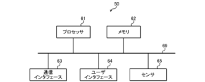
- FIG. 6 is a diagram showing an example of the hardware configuration of the image processing device 50.
- the image processing device 50 shown in FIG. 5 includes, for example, a processor 61, a memory 62, a communication interface 63, a user interface 64, and a sensor 65, as shown in FIG.
- Processor 61, memory 62, communication interface 63, user interface 64, and sensor 65 are connected by bus 69, for example.
- the processor 61 is a circuit that performs signal processing, and is, for example, a CPU that controls the entire image processing device 50. Note that the processor 61 may be realized by other digital circuits such as an FPGA or a DSP (Digital Signal Processor). Further, the processor 61 may be realized by combining a plurality of digital circuits.
- the memory 62 includes, for example, a main memory and an auxiliary memory.
- the main memory is, for example, RAM (Random Access Memory).
- the main memory is used as a work area for the processor 61.
- the auxiliary memory is, for example, nonvolatile memory such as a magnetic disk or flash memory.
- Various programs for operating the image processing device 50 are stored in the auxiliary memory.
- the program stored in the auxiliary memory is loaded into the main memory and executed by the processor 61.
- auxiliary memory may include a portable memory that is removable from the image processing device 50.
- Portable memories include memory cards such as USB (Universal Serial Bus) flash drives and SD (Secure Digital) memory cards, external hard disk drives, and the like.
- the communication interface 63 is a communication interface that communicates with a device external to the image processing device 50.
- the communication interface 63 includes at least one of a wired communication interface that performs wired communication and a wireless communication interface that performs wireless communication.
- Communication interface 63 is controlled by processor 61 .
- the user interface 64 includes, for example, an input device that accepts operation input from the user, an output device that outputs information to the user, and the like.
- the input device can be realized by, for example, keys (for example, a keyboard), a remote control, or the like.
- the output device can be realized by, for example, a display or a speaker.
- a touch panel 51 implements an input device and an output device.
- User interface 64 is controlled by processor 61.
- the image processing device 50 uses the user interface 64 to accept various specifications from the user.
- the sensor 65 includes an imaging device that has an imaging optical system and an imaging element and is capable of capturing an image, a space recognition sensor that can three-dimensionally recognize the space around the image processing device 50, and the like.
- the imaging device includes, for example, an imaging device provided on the back side of the image processing device 50 shown in FIG. 5.
- LIDAR Light Detection and Ranging
- the spatial recognition sensor is not limited to this, and may be various sensors such as a radar that emits radio waves or an ultrasonic sensor that emits ultrasonic waves.
- FIG. 7 is a diagram illustrating an example of a physical space in which the image processing device 50 is used. As shown in FIG. 7, for example, a user of the image processing device 50 brings the image processing device 50 into a physical space 70, which is a physical space where the projection device 10 is installed.
- the image processing device 50 recognizes the physical space 70 using a space recognition sensor. Specifically, the image processing device 50 defines one horizontal direction in the physical space 70 as the X axis, the direction of gravity in the physical space 70 as the Y axis, and the direction perpendicular to the X and Y axes in the physical space 70 as the Z axis. , the physical space 70 is recognized by a world coordinate system consisting of an X-axis, a Y-axis, and a Z-axis.
- the image processing device 50 displays a captured image based on the captured data obtained by imaging with the imaging device as a through image (live view) to the user on the touch panel 51.
- the imaging data is an example of first image data.
- the captured image is an example of the first image.
- the virtual projection surface can be determined relatively easily by using information about that surface.
- Position and orientation can be determined.
- the position and orientation of the virtual projection device can be determined by determining and presenting the installable range of the virtual projection device from the virtual projection plane and having the user specify a position within the installable range.
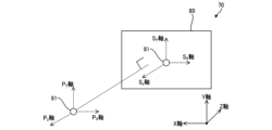
- FIG. 8 is a diagram illustrating an example of a state in which the orientation of the virtual projection plane is undetermined.
- the virtual projection plane installation position 81 is the installation position of the virtual projection plane 80 , which is the virtual projection plane 11 , in the physical space 70 .
- the virtual projection plane installation position 81 is one point included in the virtual projection plane 80.
- the virtual projection plane installation position 81 is the center point of the rectangular virtual projection plane 80.
- the virtual projection plane installation position 81 does not need to be included in the virtual projection plane 80 as long as it is a position that defines the position of the virtual projection plane 80 .
- the horizontal direction of the virtual projection plane 80 is defined as the S X axis
- the vertical direction of the virtual projection plane 80 is defined as the S Y axis
- the direction perpendicular to the virtual projection plane 80 is defined as the S Z axis.
- FIG. 9 is a diagram illustrating an example of determining the orientation of the virtual projection device by determining the orientation of the virtual projection plane 80.
- the virtual projection device installation position 91 is the installation position of the virtual projection device, which is the virtual projection device 10, in the physical space 70.
- the virtual projection device installation position 91 is one point included in the virtual projection device.
- the virtual projection device installation position 91 is a position corresponding to the projection unit 1 (for example, the lens 34) of the projection device 10.
- the virtual projection device installation position 91 does not need to be included in the virtual projection device as long as it is a position that defines the position of the virtual projection device.
- the vertical direction of the virtual projection device be the P Y axis
- the horizontal direction of the virtual projection device be the P X axis
- the front-rear direction (projection direction) of the virtual projection device be the P Z axis.
- the projection distance D from the virtual projection device to the virtual projection plane 80 can be determined. Then, the size (width and height) of the virtual projection plane 80 can be determined based on the projection distance D.
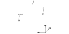
- FIG. 10 is a diagram illustrating an example of a method of specifying a position in the physical space 70.
- a three-dimensional orthogonal coordinate system centered on the position of the camera (image processing device 50) that captures and displays the captured image is defined as follows: T X is the horizontal direction of the camera, T Y is the vertical direction of the camera, and the depth direction of the camera is defined as TZ .
- the image processing device 50 displays the position designation image on the touch panel 51.
- the position designation image is created by adding an image of the position object P1 to the captured image so that the virtual position object P1 (for example, a sphere) appears to exist at a position moved by a distance d1 from the camera position to TZ in the physical space 70. This is a superimposed image.
- the image processing device 50 also receives an operation from the user instructing to change the distance d1.
- the user points the imaging device of the image processing device 50 at a desired position in the physical space 70, and sets the camera position and position.
- the position and orientation of the image processing device 50 are adjusted so that the desired position on the image processing device 50 is located on the straight line connecting the object P1.
- the user also adjusts the distance d1 by operating the image processing device 50 so that the desired position in the physical space 70 matches the positional object P1.
- the user performs an instruction position determination operation on the image processing device 50 in a state where the desired position in the physical space 70 and the position object P1 match.
- the image processing device 50 determines the position of the position object P1 at that time as the position specified by the user in the physical space 70. Thereby, the user can specify an arbitrary position in the physical space 70 to the image processing device 50, for example, as the virtual projection plane installation position 81 or the virtual projection device installation position 91.
- FIG. 11 is a diagram showing an example of a virtual projection device installation position 91, a virtual projection plane installation position 81, and a reference point.
- the image processing device 50 receives the designation of the virtual projection device installation position 91, the virtual projection plane installation position 81, and the reference point 111 from the user using the designation method shown in FIG. 10, for example.
- the virtual projection plane installation position 81 is a first position corresponding to the position of the virtual projection plane 80 in the physical space 70.
- the reference point 111 is a second position in the physical space 70 that serves as a reference for the orientation of the virtual projection plane 80, and is a position that is not on a plane that includes the virtual projection plane 80.
- the reference point 111 is, for example, the virtual projection device installation position 91.
- the image processing device 50 only needs to accept the position designated as the virtual projection device installation position 91 as the reference point 111, and does not accept the designation of the reference point 111 separately from the virtual projection device installation position 91. It's okay.
- FIG. 12 is a diagram showing a first example of the positional relationship between the virtual projection plane installation position 81 and the reference point 111.
- FIG. 13 is a diagram showing a second example of the positional relationship between the virtual projection plane installation position 81 and the reference point 111.
- a plane passing through the virtual projection plane installation position 81 and the reference point 111 specified by the user and parallel to the gravity direction (Y-axis) of the physical space 70 is defined as the installation position plane.
- a Y-axis that is the same as the Y-axis in the physical space 70 and an X'-axis perpendicular to the Y-axis are set.
- the Y-axis in the installation position plane is a vertical direction
- the X' axis in the installation position plane is horizontal.
- the first angle ⁇ is defined by the first line segment S1 connecting the reference point 111 (second position) and the virtual projection plane installation position 81 (first position) and the X' axis passing through the reference point 111 on the installation position plane. This is the angle formed by the parallel second line segment S2. That is, the first angle ⁇ is the first line segment S1 connecting the reference point 111 (second position) and the virtual projection plane installation position 81 (first position) in the physical space 70, and the horizontal line that includes the reference point 111. It is the angle formed by a plane.
- the image processing device 50 sets the orientation of the virtual projection plane 80 so that the Y-axis of the physical space 70 and the SY - axis of the virtual projection plane 80 are parallel.
- the image processing device 50 sets the orientation of the virtual projection plane 80 so that the Y axis of the physical space 70 and the SZ axis of the virtual projection plane 80 are parallel.
- the Y axis and the SZ axis are opposed to each other in the figure, the same applies when the Y axis and the SZ axis are in the same direction (floor projection).
- the image processing device 50 changes the orientation of the virtual projection plane 80 to a plane parallel to the direction of gravity (FIG. 12) or The plane perpendicular to the direction of gravity (Fig. 13) is determined.
- the orientation of the virtual projection plane 80 can be determined according to the positional relationship between the virtual projection plane installation position 81 and the reference point 111.
- the threshold value can be set to 80 degrees as an example, but is not limited to this and can be set arbitrarily.
- FIG. 14 is a diagram illustrating an example of determining the orientation of the virtual projection plane 80 when the first angle ⁇ is less than the threshold value. If the first angle ⁇ is less than the threshold, the S Y axis of the virtual projection plane 80 is determined in the vertical direction as shown in FIG. 12, but the S X axis and the S Z axis of the virtual projection plane 80 are undetermined. It is in a state of
- the image processing device 50 aligns the S , Determine the S Z axis. This determines the orientation of the virtual projection plane 80.
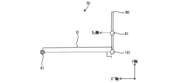
- FIG. 15 is a diagram showing an example of the projection distance D when the first angle ⁇ is less than the threshold value.
- FIG. 16 is a diagram illustrating an example of determining the orientation of the virtual projection plane 80 when the first angle ⁇ is equal to or greater than the threshold value.
- the SZ axis of the virtual projection plane 80 is determined in the vertical direction as shown in FIG. 13, but the SX axis and the SY axis of the virtual projection plane 80 are undetermined. It is in a state of
- the image processing device 50 aligns the S , SY Determine the Y axis. This determines the orientation of the virtual projection plane 80.
- FIG. 17 is a diagram showing an example of the projection distance D when the first angle ⁇ is equal to or greater than the threshold value.
- FIG. 18 is a flowchart illustrating an example of processing by the image processing device 50.
- the image processing device 50 executes the processing shown in FIG. 18, for example.
- the image processing device 50 determines the virtual projection device installation position 91, the virtual projection plane installation position 81, and the reference point 111 (step S11). For example, the image processing device 50 receives the designation of the virtual projection device installation position 91, the virtual projection plane installation position 81, and the reference point 111 as shown in FIG. 11 from the user using the designation method shown in FIG.
- the image processing device 50 calculates the positional relationship between the virtual projection plane installation position 81 determined in step S11 and the reference point 111 (step S12). For example, the image processing device 50 calculates the first angle ⁇ shown in FIGS. 12 and 13.
- the image processing device 50 determines the orientation of the virtual projection plane 80 based on the positional relationship between the virtual projection plane installation position 81 and the reference point 111 calculated in step S12 (step S13). For example, as shown in FIGS. 12 and 13, the image processing device 50 adjusts the S Y axis and the S Z axis of the virtual projection plane 80 based on the magnitude of the first angle ⁇ (result of comparison with the threshold value). It is determined which direction should be the same as the Y-axis of the physical space 70. Furthermore, the image processing device 50 determines the remaining axes of the virtual projection plane 80 to face the reference point 111, as shown in FIGS. 14 and 16.
- the image processing device 50 determines the orientation of the virtual projection device based on the orientation of the virtual projection plane 80 determined in step S13 (step S14). For example, as described in FIG. 9, the image processing device 50 sets the P Y axis of the virtual projection device in the same direction as the S Y axis of the virtual projection plane 80, and sets the P Z axis of the virtual projection device in the same direction as the S Y axis of the virtual projection plane 80. By setting the direction to be the same as the SZ axis of 80, the direction of the virtual projection device is determined.
- the image processing device 50 calculates the projection distance D between the virtual projection device and the virtual projection plane 80 based on the orientation of the virtual projection device determined in step S14 (step S15). For example, the image processing device 50 calculates the distance between the projection center 151 without lens shift and the virtual projection device installation position 91 as the projection distance D, as shown in FIGS. 15 and 17.
- the size of the virtual projection plane 80 is determined based on the projection distance D calculated in step S15 (step S16).
- the image processing device 50 determines the width and height of the virtual projection plane 80 based on the specifications (for example, the angle of view and aspect ratio) of the projection device 10 represented by the virtual projection device and the projection distance D.
- the position (virtual projection device installation position 91) and orientation of the virtual projection device, and the position (virtual projection surface installation position 81), orientation, and size of the virtual projection plane 80 are determined.
- the image processing device 50 uses this information to create a virtual projection device image representing the virtual projection device and a virtual projection plane image representing the virtual projection surface 80 in the physical space 70 by the image processing device 50. It is superimposed on the captured image represented by the captured image data obtained by imaging (step S17).
- the image processing device 50 displays the superimposed image obtained in step S17 as an arrangement support image on the touch panel 51 (step S18).
- the user places the projection device 10 and the projection surface 11 in the physical space 70 at the position and orientation determined based on the virtual projection device installation position 91 and the virtual projection surface installation position 81 specified in step S11.
- the placement support image is an example of the second image.
- the placement support image data representing the placement support image is an example of second image data.
- the image processing device 50 may re-execute steps S17 and S18 each time the position or orientation of the image processing device 50 in the physical space 70 changes (that is, each time the captured image changes). In other words, the image processing device 50 may update the superimposed virtual projection device image and virtual projection plane image and their arrangement in the placement support image to be displayed, in accordance with the changed imaging data.
- FIG. 19 is a diagram illustrating an example of recalculation of the projection distance D when the user changes the orientation of the virtual projection plane 80.
- the image processing device 50 receives an instruction operation to change the orientation of the virtual projection plane 80 from the user, the image processing device 50 changes the orientation of the virtual projection plane 80 based on the instruction operation received from the user. Then, the size of the virtual projection plane 80 is changed based on the changed orientation of the virtual projection plane 80 and the virtual projection device installation position 91, and the placement support image (placement support image data) to be displayed is updated.
- FIG. 19 shows a virtual projection plane 80 whose orientation has been changed.
- the perpendicular line 191 is a perpendicular line drawn from the virtual projection device installation position 91 to a plane that passes through the virtual projection plane installation position 81 and is parallel to the changed virtual projection plane 80 .
- the image processing device 50 recalculates the length of the perpendicular line 191 as a new projection distance D. Furthermore, the image processing device 50 re-determines the size of the virtual projection plane 80 based on the calculated projection distance D.
- the virtual projection plane image to be superimposed on the captured image is updated based on the changed orientation of the virtual projection plane 80 and the re-determined size of the virtual projection plane 80, and placement support that updates the virtual projection plane image Display the image (second image).
- the process when the user changes the orientation of the virtual projection plane 80 has been described. For example, after the process shown in FIG . If received from the user, the position of the virtual projection plane 80 in the SZ direction may be changed based on the instruction operation received from the user. In this case, the image processing device 50 calculates a projection distance D based on the changed position of the virtual projection plane 80 in the SZ direction and the virtual projection device installation position 91, and performs virtual projection based on the calculated projection distance D. The size of the surface 80 is changed and the displayed placement support image (placement support image data) is updated.
- FIG. 20 is a diagram illustrating an example of determining the position of the virtual projection plane 80 based on detection of a plane that serves as a reference for the position of the virtual projection plane 80.
- the image processing device 50 detects a line or plane serving as a reference for the position of the virtual projection plane 80 in the physical space 70, the image processing device 50 detects a virtual plane on the plane including the virtual projection plane 80 based on the position of the detected line or plane.
- the position of the projection plane 80 may be determined and the placement support image may be displayed.
- the image processing device 50 detects the floor surface 201 using the spatial recognition sensor. Since the floor surface 201 is perpendicular to the direction of the virtual projection surface 80, the image processing device 50 recognizes that the floor surface 201 is a surface that serves as a reference for the position of the virtual projection surface 80.
- step S16 and step S17 shown in FIG. 18 the image processing device 50 determines whether the end (lower end) of the virtual projection surface 80 is The virtual projection plane installation position 81 determined in step S11 is changed so that it is in contact with the floor surface 201.
- the virtual projection device image and the virtual projection plane image are superimposed on the captured image in step S17 with the virtual projection plane 80 being translated downward compared to the case where the virtual projection plane installation position 81 is not changed.
- Ru The determination of the position of the virtual projection plane 80 based on the detection of a plane serving as a reference for the position of the virtual projection plane 80 is performed in steps S17 and S18 due to changes in the position and orientation of the image processing device 50 in the physical space 70, as described above. It may also be executed when re-executing.
- the image processing device 50 may be changed so that the distance between the surface 201) and the end of the virtual projection plane 80 becomes a predetermined offset value.
- the offset value may be predetermined or may be specified by the user.
- the image processing device 50 determines the final position of the virtual projection plane 80 based on the virtual projection device installation position 91. Before determining the orientation, the orientation of the virtual projection plane 80 is temporarily determined using the position of the image processing device 50 (camera position), and the placement support image is displayed based on the orientation of the virtual projection plane 80. It's okay.
- 21 and 22 are diagrams illustrating an example of determining the temporary orientation of the virtual projection plane 80 based on the camera position when the first angle ⁇ is less than the threshold value. If the first angle ⁇ is less than the threshold, the S Y axis of the virtual projection plane 80 is determined in the vertical direction as shown in FIG. 12, but the S X axis and the S Z axis of the virtual projection plane 80 are undetermined. It is in a state of The camera position 211 is the position of the image processing device 50.
- the angle between the SZ axis of the virtual projection plane 80 and the line segment connecting the virtual projection plane installation position 81 and the camera position 211 is large, making it difficult to see the virtual projection plane 80 from the camera position 211. It is in a state.
- the image processing device 50 for example, in response to a user's operation or automatically, adjusts the virtual projection plane 80 so that the S and Z axes face the camera position 211 when viewed in a plane perpendicular to the Y axis. Tentatively determine the S X axis and the S Z axis.
- the direction of the virtual projection plane 80 becomes the direction based on the camera position 211, and the virtual projection plane 80 becomes easily visible from the camera position 211.
- the image processing device 50 repeatedly updates the orientation of the virtual projection plane 80 shown in FIGS. 21 and 22 as the user moves (moves the camera position 211).
- the image processing device 50 sets the camera position 211 at that time or a point specified by the user as the reference point 111.
- the virtual projection device installation position 91 may be set before the reference point 111 is set, or may be set after the reference point 111 is set.
- the virtual projection device installation position 91, the virtual projection plane installation position 81, and the reference point 111 are determined, so that the same processing as steps S12 to S18 shown in FIG. 18 is executed.
- the virtual projection plane 80 can be easily seen by the user even if the reference point 111 is not yet determined.
- the image processing device 50 similarly determines the orientation of the virtual projection plane 80 when the first angle ⁇ is greater than or equal to the threshold.
- the orientation of the virtual projection plane 80 may be determined temporarily based on the camera position.
- the image processing device 50 determines the orientation of the virtual projection surface 80 based on the positional relationship between the virtual projection surface installation position 81 and the reference point 111, and the position of the image processing device 50 (imaging device). Good too.
- the processor 61 of the image processing device 50 acquires the first image data obtained by imaging the physical space 70 with the imaging device of the sensor 65.
- the processor 61 of the image processing device 50 also detects a virtual projection plane installation position 81 (first position) corresponding to the position of the virtual projection plane 80 in the physical space 70 and a virtual A reference point 111 (second position) serving as a reference for the orientation of the projection surface 80 is determined, and the orientation of the virtual projection surface 80 is determined based on the positional relationship between the virtual projection surface installation position 81 and the reference point 111.
- Virtual projection plane data representing the virtual projection plane 80 is generated.
- the processor 61 of the image processing device 50 Based on the first image data and the virtual projection plane data, the processor 61 of the image processing device 50 generates a second image representing a second image in which the virtual projection plane 80 is displayed on the first image represented by the first image data. data is generated, and the second image data is output to the touch panel 51 (output destination).
- the image processing device 50 is not limited to such a configuration.
- the image processing device 50 may be an information terminal such as a smartphone or a personal computer.
- the image processing device 50 can display the second image on the other device by transmitting the generated second image to the other device. You may also perform control to In this case, the image processing device 50 may be a device that does not include a display device.
- the captured image representing the physical space 70 is an image obtained by imaging by the imaging device of the image processing device 50.
- the image processing device 50 may receive the information from the image processing device 50 .
- the image processing device 50 may be a device that does not include an imaging device.
- the reference point 111 is the virtual projection device installation position 91
- the reference point 111 is not limited to this, and may be the position of the imaging device (image processing device 50), or may be the location of the virtual projection plane 80. It may be the position of the observer observing, or a combination of these positions.
- the position of the imaging device (image processing device 50) is, for example, the origin of the world coordinate system when the image processing device 50 recognizes the physical space 70, so there is no need to accept a designation from the user.
- the image processing device 50 receives a designation from the user using the designation method shown in FIG. 10, for example.
- image processing program Note that the image processing method described in the above-described embodiments can be realized by executing a prepared image processing program on a computer.
- This image processing program is recorded on a computer-readable storage medium, and is executed by being read from the storage medium.
- the image processing program may be provided in a form stored in a non-transitory storage medium such as a flash memory, or may be provided via a network such as the Internet.
- the computer that executes this image processing program may be included in the image processing device, or may be included in an electronic device such as a smartphone, tablet terminal, or personal computer that can communicate with the image processing device. Alternatively, it may be included in a server device that can communicate with these image processing devices and electronic devices.
- An image processing device comprising a processor, The above processor is Obtaining first image data obtained by imaging the space with an imaging device, determining a first position corresponding to the position of the virtual projection plane in the space and a second position serving as a reference for the orientation of the virtual projection plane; determining the orientation of the virtual projection plane based on the positional relationship between the first position and the second position and generating virtual projection plane data representing the virtual projection plane; Based on the first image data and the virtual projection plane data, generate second image data representing a second image in which the virtual projection plane is displayed on the first image represented by the first image data; Output the second image data to the output destination, Image processing device.
- the second position is a position that is not on a plane including the virtual projection plane, Image processing device.
- the image processing device is at least one of an installation position of a virtual projection device corresponding to the virtual projection plane, a position of the imaging device, and a position of an observer observing the virtual projection plane.
- Image processing device is at least one of an installation position of a virtual projection device corresponding to the virtual projection plane, a position of the imaging device, and a position of an observer observing the virtual projection plane.
- the image processing device is Calculating a first angle that is the angle between a first line segment connecting the second position and the first position and a plane that includes the second position and is perpendicular or horizontal to the direction of gravity; determining the orientation of the virtual projection plane based on the magnitude of the first angle; Image processing device.
- the image processing device determines the orientation of the virtual projection plane to be a plane parallel to the direction of gravity or a plane perpendicular to the direction of gravity, depending on the comparison result between the first angle and the threshold value.
- Image processing device determines the orientation of the virtual projection plane to be a plane parallel to the direction of gravity or a plane perpendicular to the direction of gravity, depending on the comparison result between the first angle and the threshold value.
- the image processing device determines the first position and the second position based on instructions received from a user. Image processing device.
- the image processing device determines the orientation of the virtual projection plane based on the positional relationship and the installation position of the virtual projection device corresponding to the virtual projection plane. Image processing device.
- the image processing device determines the orientation of the virtual projection plane based on the positional relationship and the position of the imaging device. Image processing device.
- the image processing device determines the size of the virtual projection plane based on the orientation of the virtual projection plane and the installation position of the virtual projection device corresponding to the virtual projection plane, and generates the virtual projection plane data.
- Image processing device determines the size of the virtual projection plane based on the orientation of the virtual projection plane and the installation position of the virtual projection device corresponding to the virtual projection plane, and generates the virtual projection plane data.
- the image processing device is changing the orientation of the virtual projection surface based on an instruction to change the orientation of the virtual projection surface received from the user; changing the size of the virtual projection plane based on the changed orientation of the virtual projection plane and the installation position of the virtual projection device; updating the virtual projection plane data and the second image data; Image processing device.
- the image processing device according to any one of (1) to (10), When the processor detects a line or plane serving as a reference for the position of the virtual projection plane in the space, the processor detects the position of the virtual projection plane on the plane including the virtual projection plane based on the position of the line or plane. Determine and generate the above virtual projection plane data, Image processing device.
- the image processing device is determining the position of the virtual projection plane such that the distance between the position of the line or plane and the end of the virtual projection plane is a predetermined offset value; Image processing device.
- the image processing device is changing the position of the virtual projection plane based on an instruction to change the position of the virtual projection plane in a direction perpendicular to the virtual projection plane received from a user; changing the size of the virtual projection plane based on the changed position of the virtual projection plane and the installation position of the virtual projection device corresponding to the virtual projection plane; updating the virtual projection plane data and the second image data; Image processing device.
- the image processing device according to any one of (1) to (13), Provided in an information processing terminal including the imaging device and the display device,
- the output destination is the display device, Image processing device.
- a processor included in the image processing device Obtaining first image data obtained by imaging the space with an imaging device, determining a first position corresponding to the position of the virtual projection plane in the space and a second position serving as a reference for the orientation of the virtual projection plane; determining the orientation of the virtual projection plane based on the positional relationship between the first position and the second position and generating virtual projection plane data representing the virtual projection plane; Based on the first image data and the virtual projection plane data, generate second image data representing a second image in which the virtual projection plane is displayed on the first image represented by the first image data; Output the second image data to the output destination, Image processing method.
- the processor included in the image processing device Obtaining first image data obtained by imaging the space with an imaging device, determining a first position corresponding to the position of the virtual projection plane in the space and a second position serving as a reference for the orientation of the virtual projection plane; determining the orientation of the virtual projection plane based on the positional relationship between the first position and the second position and generating virtual projection plane data representing the virtual projection plane; Based on the first image data and the virtual projection plane data, generate second image data representing a second image in which the virtual projection plane is displayed on the first image represented by the first image data; Output the second image data to the output destination, An image processing program to perform processing.
Landscapes
- Engineering & Computer Science (AREA)
- Physics & Mathematics (AREA)
- Computer Hardware Design (AREA)
- General Physics & Mathematics (AREA)
- Theoretical Computer Science (AREA)
- Multimedia (AREA)
- Signal Processing (AREA)
- Image Processing (AREA)
Abstract
投影面や投影装置の配置に関するユーザの利便性を向上させることができる、画像処理装置、画像処理方法及び画像処理プログラムを提供することができる。 画像処理装置(50)は、撮像装置により物理空間(70)を撮像して得られた第1画像データを取得する。また、画像処理装置(50)は、物理空間(70)における、仮想投影面(80)の位置に対応する第1位置と、仮想投影面(80)の向きの基準となる第2位置と、を決定する。また、画像処理装置(50)は、第1位置と第2位置との位置関係に基づいて仮想投影面(80)の向きを決定して仮想投影面(80)を表す仮想投影面データを生成する。また、画像処理装置(50)は、第1画像データ及び仮想投影面データに基づいて、第1画像データが表す第1画像に仮想投影面が表示される第2画像を表す第2画像データを生成し、第2画像データを出力先に出力する。
Description
本発明は、画像処理装置、画像処理方法及び画像処理プログラムに関する。
特許文献1には、プロジェクタの配置設計に関する負担を軽減するために、プロジェクタによる投影に関する投影条件に基づいて、プロジェクタの配置に関するプロジェクタ配置情報を出力する情報処理装置が記載されている。
特許文献2には、画像投射装置による画像の投射に関する設定情報を取得し、取得した設定情報に基づいて、複数の画像投射装置と、その複数の画像投射装置により投射される複数の画像の各々の表示領域とを含むシミュレーション画像を生成する情報処理装置が記載されている。
特許文献3には、3方向への投影を容易に行うために、対象物に対して映像を投影可能な投影部を設けた本体を載置面に載置するための第1載置部、第2載置部、第3載置部を本体に設け、互いに異なる方向に向けて第1載置部、第2載置部、第3載置部を設けた投影玩具が記載されている。
本開示の技術に係る1つの実施形態は、投影面や投影装置の配置に関するユーザの利便性を向上させることができる、画像処理装置、画像処理方法及び画像処理プログラムを提供する。
本発明の一態様の画像処理装置は、プロセッサを備える画像処理装置であって、上記プロセッサは、撮像装置により空間を撮像して得られた第1画像データを取得し、上記空間における、仮想投影面の位置に対応する第1位置と、上記仮想投影面の向きの基準となる第2位置と、を決定し、上記第1位置と上記第2位置との位置関係に基づいて上記仮想投影面の向きを決定して上記仮想投影面を表す仮想投影面データを生成し、上記第1画像データ及び上記仮想投影面データに基づいて、上記第1画像データが表す第1画像に上記仮想投影面が表示される第2画像を表す第2画像データを生成し、第2画像データを出力先に出力するものである。
本発明の一態様の画像処理方法は、画像処理装置が備えるプロセッサが、撮像装置により空間を撮像して得られた第1画像データを取得し、上記空間における、仮想投影面の位置に対応する第1位置と、上記仮想投影面の向きの基準となる第2位置と、を決定し、上記第1位置と上記第2位置との位置関係に基づいて上記仮想投影面の向きを決定して上記仮想投影面を表す仮想投影面データを生成し、上記第1画像データ及び上記仮想投影面データに基づいて、上記第1画像データが表す第1画像に上記仮想投影面が表示される第2画像を表す第2画像データを生成し、第2画像データを出力先に出力するものである。
本発明の一態様の画像処理プログラムは、画像処理装置が備えるプロセッサに、撮像装置により空間を撮像して得られた第1画像データを取得し、上記空間における、仮想投影面の位置に対応する第1位置と、上記仮想投影面の向きの基準となる第2位置と、を決定し、上記第1位置と上記第2位置との位置関係に基づいて上記仮想投影面の向きを決定して上記仮想投影面を表す仮想投影面データを生成し、上記第1画像データ及び上記仮想投影面データに基づいて、上記第1画像データが表す第1画像に上記仮想投影面が表示される第2画像を表す第2画像データを生成し、第2画像データを出力先に出力する、処理を実行させるためのものである。
本発明によれば、投影面や投影装置の配置に関するユーザの利便性を向上させることができる、画像処理装置、画像処理方法及び画像処理プログラムを提供することができる。
以下、本発明の実施形態の例について、図面を参照して説明する。
(実施形態)
<実施形態の画像処理装置による配置支援対象の投影装置10>
図1は、実施形態の画像処理装置による配置支援対象の投影装置10の一例を示す模式図である。
<実施形態の画像処理装置による配置支援対象の投影装置10>
図1は、実施形態の画像処理装置による配置支援対象の投影装置10の一例を示す模式図である。
実施形態の画像処理装置は、例えば投影装置10の配置支援に用いることができる。投影装置10は、投影部1と、制御装置4と、操作受付部2と、を備える。投影部1は、例えば液晶プロジェクタ又はLCOS(Liquid Crystal On Silicon)を用いたプロジェクタ等によって構成される。以下では、投影部1が液晶プロジェクタであるものとして説明する。
制御装置4は、投影装置10による投影の制御を行う制御装置である。制御装置4は、各種のプロセッサにより構成される制御部と、各部と通信するための通信インタフェース(図示省略)と、ハードディスク、SSD(Solid State Drive)、又はROM(Read Only Memory)等のメモリ4aと、を含む装置であり、投影部1を統括制御する。
制御装置4の制御部の各種のプロセッサとしては、プログラムを実行して各種処理を行う汎用的なプロセッサであるCPU(Central Processing Unit)、FPGA(Field Programmable Gate Array)等の製造後に回路構成を変更可能なプロセッサであるプログラマブルロジックデバイス(Programmable Logic Device:PLD)、又はASIC(Application Specific Integrated Circuit)等の特定の処理を実行させるために専用に設計された回路構成を有するプロセッサである専用電気回路等が含まれる。
これら各種のプロセッサの構造は、より具体的には、半導体素子等の回路素子を組み合わせた電気回路である。制御装置4の制御部は、各種のプロセッサのうちの1つで構成されてもよいし、同種又は異種の2つ以上のプロセッサの組み合わせ(例えば、複数のFPGAの組み合わせ又はCPUとFPGAの組み合わせ)で構成されてもよい。
操作受付部2は、ユーザからの各種の操作を受け付けることにより、ユーザからの指示を検出する。操作受付部2は、制御装置4に設けられたボタン、キー、ジョイスティック等であってもよいし、制御装置4の遠隔操作を行うリモートコントローラからの信号を受け付ける受信部等であってもよい。
被投影物6は、投影部1によって投影画像が表示される投影面を有する、スクリーンや壁などの物体である。図1に示す例では、被投影物6は、被投影物6の投影面は矩形の平面である。図1における被投影物6の上下左右が、実際の被投影物6の上下左右であるとする。
一点鎖線で図示する投影面11は、被投影物6のうち、投影部1により投影光が照射される領域である。図1に示す例では、投影面11は矩形である。投影面11は、投影部1により投影が可能な投影可能範囲の一部又は全部である。
なお、投影部1、制御装置4、及び操作受付部2は、例えば一個の装置により実現される(例えば図3,図4参照)。又は、投影部1、制御装置4、及び操作受付部2は、互いに通信を行うことにより連携する、それぞれ別の装置であってもよい。
<図1に示す投影部1の内部構成>
図2は、図1に示す投影部1の内部構成の一例を示す模式図である。
図2は、図1に示す投影部1の内部構成の一例を示す模式図である。
図2に示すように、投影部1は、光源21と、光変調部22と、投影光学系23と、制御回路24と、を備える。
光源21は、レーザ又はLED(Light Emitting Diode)等の発光素子を含み、例えば白色光を出射する。
光変調部22は、光源21から出射されて図示省略の色分離機構によって赤、青、緑の3色に分離された各色光を、画像情報に基づいて変調して各色画像を出射する3つの液晶パネルによって構成される。この3つの液晶パネルにそれぞれ赤、青、緑のフィルタを搭載し、光源21から出射された白色光を、各液晶パネルにて変調して各色画像を出射させてもよい。
投影光学系23は、光源21及び光変調部22からの光が入射されるものであり、少なくとも1つのレンズを含む、例えばリレー光学系によって構成されている。投影光学系23を通過した光は被投影物6に投影される。
被投影物6のうち、光変調部22の全範囲を透過する光が照射される領域が、投影部1により投影が可能な投影可能範囲となる。この投影可能範囲のうち、光変調部22から実際に透過する光が照射される領域が投影面11となる。例えば、光変調部22のうち光が透過する領域の大きさ、位置、及び形状を制御することにより、投影可能範囲において、投影面11の大きさ、位置、及び形状が変化する。
制御回路24は、制御装置4から入力される表示用データに基づいて、光源21、光変調部22、及び投影光学系23を制御することにより、被投影物6にこの表示用データに基づく画像を投影させる。制御回路24に入力される表示用データは、赤表示用データと、青表示用データと、緑表示用データとの3つによって構成される。
また、制御回路24は、制御装置4から入力される命令に基づいて、投影光学系23を変化させることにより、投影部1の投影面11(図1参照)の拡大や縮小を行う。また、制御装置4は、操作受付部2によって受け付けられたユーザからの操作に基づいて投影光学系23を変化させることにより、投影部1の投影面11の移動を行ってもよい。
また、投影装置10は、投影光学系23のイメージサークルを維持しつつ、投影面11を機械的又は光学的に移動させるシフト機構を備える。投影光学系23のイメージサークルは、投影光学系23に入射した投影光が、光量落ち、色分離、周辺湾曲などの点から適正に投影光学系23を通過する領域である。
シフト機構は、光学系シフトを行う光学系シフト機構と、電子シフトを行う電子シフト機構と、の少なくともいずれかにより実現される。
光学系シフト機構は、例えば、投影光学系23を光軸に垂直な方向に移動させる機構(例えば図3,図4参照)、又は、投影光学系23を移動させる代わりに光変調部22を光軸に垂直な方向に移動させる機構である。また、光学系シフト機構は、投影光学系23の移動と光変調部22の移動とを組み合わせて行うものであってもよい。
電子シフト機構は、光変調部22において光を透過させる範囲を変化させることによる疑似的な投影面11のシフトを行う機構である。
また、投影装置10は、投影光学系23のイメージサークルとともに投影面11を移動させる投影方向変更機構を備えてもよい。投影方向変更機構は、機械的な回転で投影部1の向きを変更することにより、投影部1の投影方向を変化させる機構である(例えば図3,図4参照)。
<投影装置10の機械的構成>
図3は、投影装置10の外観構成を示す模式図である。図4は、図3に示す投影装置10の光学ユニット106の断面模式図である。図4は、図3に示す本体部101から出射される光の光路に沿った面での断面を示している。
図3は、投影装置10の外観構成を示す模式図である。図4は、図3に示す投影装置10の光学ユニット106の断面模式図である。図4は、図3に示す本体部101から出射される光の光路に沿った面での断面を示している。
図3に示すように、投影装置10は、本体部101と、本体部101から突出して設けられた光学ユニット106と、を備える。図3に示す構成において、操作受付部2と、制御装置4と、投影部1における光源21、光変調部22、及び制御回路24と、は本体部101に設けられる。投影部1における投影光学系23は光学ユニット106に設けられる。
光学ユニット106は、本体部101に支持される第1部材102と、第1部材102に支持された第2部材103と、を備える。
なお、第1部材102と第2部材103は一体化された部材であってもよい。光学ユニット106は、本体部101に着脱自在に構成(換言すると交換可能に構成)されていてもよい。
本体部101は、光学ユニット106と連結される部分に光を通すための開口15a(図4参照)が形成された筐体15(図4参照)を有する。
本体部101の筐体15の内部には、図3に示すように、光源21と、光源21から出射される光を入力画像データに基づいて空間変調して画像を生成する光変調部22(図2参照)を含む光変調ユニット12と、が設けられている。
光源21から出射された光は、光変調ユニット12の光変調部22に入射され、光変調部22によって空間変調されて出射される。
図4に示すように、光変調ユニット12によって空間変調された光によって形成される画像は、筐体15の開口15aを通過して光学ユニット106に入射され、投影対象物としての被投影物6に投影されて、画像G1が観察者から視認可能となる。
図4に示すように、光学ユニット106は、本体部101の内部と繋がる中空部2Aを有する第1部材102と、中空部2Aと繋がる中空部3Aを有する第2部材103と、中空部2Aに配置された第1光学系121及び反射部材122と、中空部3Aに配置された第2光学系31、反射部材32、第3光学系33、及びレンズ34と、シフト機構105と、投影方向変更機構104と、を備える。
第1部材102は、断面外形が一例として矩形の部材であり、開口2aと開口2bが互いに垂直な面に形成されている。第1部材102は、本体部101の開口15aと対面する位置に開口2aが配置される状態にて、本体部101によって支持されている。本体部101の光変調ユニット12の光変調部22から出射された光は、開口15a及び開口2aを通って第1部材102の中空部2Aに入射される。
本体部101から中空部2Aに入射される光の入射方向を方向X1と記載し、方向X1の逆方向を方向X2と記載し、方向X1と方向X2を総称して方向Xと記載する。また、図4において、紙面手前から奥に向かう方向とその逆方向を方向Zと記載する。方向Zのうち、紙面手前から奥に向かう方向を方向Z1と記載し、紙面奥から手前に向かう方向を方向Z2と記載する。
また、方向X及び方向Zに垂直な方向を方向Yと記載し、方向Yのうち、図4において上に向かう方向を方向Y1と記載し、図4において下に向かう方向を方向Y2と記載する。図4の例では方向Y2が鉛直方向となるように投影装置10が配置されている。
図2に示した投影光学系23は、第1光学系121、反射部材122、第2光学系31、反射部材32、第3光学系33、及びレンズ34により構成される。図4には、この投影光学系23の光軸Kが示されている。第1光学系121、反射部材122、第2光学系31、反射部材32、第3光学系33、及びレンズ34は、光変調部22側からこの順に光軸Kに沿って配置されている。
第1光学系121は、少なくとも1つのレンズを含み、本体部101から第1部材102に入射された方向X1に進む光を反射部材122に導く。
反射部材122は、第1光学系121から入射された光を方向Y1に反射させる。反射部材122は、例えばミラー等によって構成される。第1部材102には、反射部材122にて反射した光の光路上に開口2bが形成されており、この反射した光は開口2bを通過して第2部材103の中空部3Aへと進む。
第2部材103は、断面外形が略T字状の部材であり、第1部材102の開口2bと対面する位置に開口3aが形成されている。第1部材102の開口2bを通過した本体部101からの光は、この開口3aを通って第2部材103の中空部3Aに入射される。なお、第1部材102や第2部材103の断面外形は任意であり、上記のものには限定されない。
第2光学系31は、少なくとも1つのレンズを含み、第1部材102から入射された光を、反射部材32に導く。
反射部材32は、第2光学系31から入射される光を方向X2に反射させて第3光学系33に導く。反射部材32は、例えばミラー等によって構成される。
第3光学系33は、少なくとも1つのレンズを含み、反射部材32にて反射された光をレンズ34に導く。
レンズ34は、第2部材103の方向X2側の端部に形成された開口3cを塞ぐ形でこの端部に配置されている。レンズ34は、第3光学系33から入射された光を被投影物6に投影する。
投影方向変更機構104は、第1部材102に対して第2部材103を回転自在に連結する回転機構である。この投影方向変更機構104によって、第2部材103は、方向Yに延びる回転軸(具体的には光軸K)の回りに回転自在に構成されている。なお、投影方向変更機構104は、光学系を回転させることができればよく、図4に示した配置位置に限定されない。また、回転機構の数も1つに限らず、複数設けられていてもよい。
シフト機構105は、投影光学系の光軸K(換言すると光学ユニット106)をその光軸Kに垂直な方向(図4の方向Y)に移動させるための機構である。具体的には、シフト機構105は、第1部材102の本体部101に対する方向Yの位置を変更することができるように構成されている。シフト機構105は、手動にて第1部材102を移動させるものの他、電動にて第1部材102を移動させるものであってもよい。
図4は、シフト機構105によって第1部材102が方向Y1側に最大限移動された状態を示している。この図4に示す状態から、シフト機構105によって第1部材102が方向Y2に移動することで、光変調部22によって形成される画像の中心(換言すると表示面の中心)と光軸Kとの相対位置が変化して、被投影物6に投影されている画像G1を方向Y2にシフト(平行移動)させることができる。
なお、シフト機構105は、光学ユニット106を方向Yに移動させる代わりに、光変調部22を方向Yに移動させる機構であってもよい。この場合でも、被投影物6に投影されている画像G1を方向Y2に移動させることができる。
<画像処理装置50の外観>
図5は、画像処理装置50の外観の一例を示す図である。画像処理装置50は、タッチパネル51を有するタブレット端末である。タッチパネル51は、タッチ操作が可能なディスプレイである。画像処理装置50は、空間への投影装置10の設置を支援するための配置支援画像をタッチパネル51により表示する。
図5は、画像処理装置50の外観の一例を示す図である。画像処理装置50は、タッチパネル51を有するタブレット端末である。タッチパネル51は、タッチ操作が可能なディスプレイである。画像処理装置50は、空間への投影装置10の設置を支援するための配置支援画像をタッチパネル51により表示する。
具体的には、画像処理装置50は、投影装置10を設置して投影を行う空間を撮像して得られた第1画像に、仮想的な投影面である仮想投影面の画像と、仮想的な投影装置である仮想投影装置の画像と、を重畳した第2画像を配置支援画像として表示する。
<画像処理装置50のハードウェア構成>
図6は、画像処理装置50のハードウェア構成の一例を示す図である。図5に示した画像処理装置50は、例えば、図6に示すように、プロセッサ61と、メモリ62と、通信インタフェース63と、ユーザインタフェース64と、センサ65と、を備える。プロセッサ61、メモリ62、通信インタフェース63、ユーザインタフェース64、及びセンサ65は、例えばバス69によって接続される。
図6は、画像処理装置50のハードウェア構成の一例を示す図である。図5に示した画像処理装置50は、例えば、図6に示すように、プロセッサ61と、メモリ62と、通信インタフェース63と、ユーザインタフェース64と、センサ65と、を備える。プロセッサ61、メモリ62、通信インタフェース63、ユーザインタフェース64、及びセンサ65は、例えばバス69によって接続される。
プロセッサ61は、信号処理を行う回路であり、例えば画像処理装置50の全体の制御を司るCPUである。なお、プロセッサ61は、FPGAやDSP(Digital Signal Processor)などの他のデジタル回路により実現されてもよい。また、プロセッサ61は、複数のデジタル回路を組み合わせて実現されてもよい。
メモリ62には、例えばメインメモリ及び補助メモリが含まれる。メインメモリは、例えばRAM(Random Access Memory)である。メインメモリは、プロセッサ61のワークエリアとして使用される。
補助メモリは、例えば磁気ディスク、フラッシュメモリなどの不揮発性メモリである。補助メモリには、画像処理装置50を動作させる各種のプログラムが記憶されている。補助メモリに記憶されたプログラムは、メインメモリにロードされてプロセッサ61によって実行される。
また、補助メモリは、画像処理装置50から取り外し可能な可搬型のメモリを含んでもよい。可搬型のメモリには、USB(Universal Serial Bus)フラッシュドライブやSD(Secure Digital)メモリカードなどのメモリカードや、外付けハードディスクドライブなどがある。
通信インタフェース63は、画像処理装置50の外部の装置との間で通信を行う通信インタフェースである。通信インタフェース63は、有線により通信を行う有線通信インタフェースと、無線により通信を行う無線通信インタフェースと、の少なくともいずれかを含む。通信インタフェース63は、プロセッサ61によって制御される。
ユーザインタフェース64は、例えば、ユーザからの操作入力を受け付ける入力デバイスや、ユーザへ情報を出力する出力デバイスなどを含む。入力デバイスは、例えばキー(例えばキーボード)やリモコンなどにより実現することができる。出力デバイスは、例えばディスプレイやスピーカなどにより実現することができる。図5に示した画像処理装置50においては、タッチパネル51によって入力デバイス及び出力デバイスが実現されている。ユーザインタフェース64は、プロセッサ61によって制御される。画像処理装置50は、ユーザインタフェース64を用いて、ユーザからの各種の指定を受け付ける。
センサ65は、撮像光学系及び撮像素子を有し撮像が可能な撮像装置や、画像処理装置50の周辺の空間を3次元的に認識可能な空間認識センサなどを含む。撮像装置は、例えば図5に示した画像処理装置50の裏面に設けられた撮像装置を含む。
空間認識センサは、一例としては、レーザ光を照射し、照射したレーザ光が物体に当たって跳ね返ってくるまでの時間を計測し、物体までの距離や方向を測定するLIDAR(Light Detection and Ranging)である。ただし、空間認識センサは、これに限らず、電波を発射するレーダや、超音波を発射する超音波センサなど各種のセンサとすることができる。
<画像処理装置50が使用される物理空間>
図7は、画像処理装置50が使用される物理空間の一例を示す図である。図7に示すように、例えば、画像処理装置50のユーザは、投影装置10の設置対象の物理空間である物理空間70に画像処理装置50を持ち込む。
図7は、画像処理装置50が使用される物理空間の一例を示す図である。図7に示すように、例えば、画像処理装置50のユーザは、投影装置10の設置対象の物理空間である物理空間70に画像処理装置50を持ち込む。
画像処理装置50は、空間認識センサにより物理空間70を認識する。具体的には、画像処理装置50は、物理空間70における水平な一方向をX軸、物理空間70における重力方向をY軸、物理空間70におけるX軸及びY軸と直交する方向をZ軸として、X軸、Y軸、及びZ軸からなるワールド座標系によって物理空間70を認識する。また、画像処理装置50は、撮像装置による撮像で得られた撮像データに基づく撮像画像をスルー画像(ライブビュー)としてタッチパネル51によりユーザに表示する。撮像データは、第1画像データの一例である。撮像画像は、第1画像の一例である。
<仮想投影面の位置と向きの基準となる面が存在しない場合の配置>
仮に、物理空間70において、壁や投影スクリーンなど、仮想投影面の位置と向きの基準となる面が存在している場合には、その面の情報を使うことで比較的容易に仮想投影面の位置と向きを決定することができる。また、仮想投影面から仮想投影装置の設置可能範囲を求めて提示し、ユーザに設置可能範囲内の位置を指定させることで、仮想投影装置の位置と向きを決めることができる。しかし、仮想投影面の位置と向きの基準となる面が存在しない場合、仮想投影面と仮想投影装置の位置と向きを決定することは困難である。これに対して、本実施例によれば、仮想投影面の位置と向きの基準となる面が存在しなくても、効率よく仮想投影装置と仮想投影面の配置を決定することが可能になる。
仮に、物理空間70において、壁や投影スクリーンなど、仮想投影面の位置と向きの基準となる面が存在している場合には、その面の情報を使うことで比較的容易に仮想投影面の位置と向きを決定することができる。また、仮想投影面から仮想投影装置の設置可能範囲を求めて提示し、ユーザに設置可能範囲内の位置を指定させることで、仮想投影装置の位置と向きを決めることができる。しかし、仮想投影面の位置と向きの基準となる面が存在しない場合、仮想投影面と仮想投影装置の位置と向きを決定することは困難である。これに対して、本実施例によれば、仮想投影面の位置と向きの基準となる面が存在しなくても、効率よく仮想投影装置と仮想投影面の配置を決定することが可能になる。
<仮想投影面の向きが未決定の状態>
図8は、仮想投影面の向きが未決定の状態の一例を示す図である。仮想投影面設置位置81は、仮想的な投影面11である仮想投影面80の物理空間70における設置位置である。例えば、仮想投影面設置位置81は、仮想投影面80に含まれる一点である。図8の例では、仮想投影面設置位置81は矩形の仮想投影面80における中心点である。ただし、仮想投影面設置位置81は、仮想投影面80の位置を規定する位置であれば、仮想投影面80に含まれていなくてもよい。
図8は、仮想投影面の向きが未決定の状態の一例を示す図である。仮想投影面設置位置81は、仮想的な投影面11である仮想投影面80の物理空間70における設置位置である。例えば、仮想投影面設置位置81は、仮想投影面80に含まれる一点である。図8の例では、仮想投影面設置位置81は矩形の仮想投影面80における中心点である。ただし、仮想投影面設置位置81は、仮想投影面80の位置を規定する位置であれば、仮想投影面80に含まれていなくてもよい。
仮想投影面80の横方向をSX軸、仮想投影面80の縦方向をSY軸、仮想投影面80に対して垂直な方向をSZ軸とする。物理空間70における仮想投影面80の仮想投影面設置位置81のみが決定されている場合、SX軸、SY軸、及びSZ軸をそれぞれワールド座標系のX軸、Y軸、及びZ軸に対してどう設定するかが決まっていない状態、すなわち仮想投影面80の向きが未決定の状態となる。
<仮想投影面80の向きの決定による仮想投影装置の向きの決定>
図9は、仮想投影面80の向きの決定による仮想投影装置の向きの決定の一例を示す図である。仮想投影装置設置位置91は、仮想的な投影装置10である仮想投影装置の物理空間70における設置位置である。例えば、仮想投影装置設置位置91は、仮想投影装置に含まれる一点である。一例としては、仮想投影装置設置位置91は、投影装置10の投影部1(例えばレンズ34)に対応する位置である。ただし、仮想投影装置設置位置91は、仮想投影装置の位置を規定する位置であれば、仮想投影装置に含まれていなくてもよい。
図9は、仮想投影面80の向きの決定による仮想投影装置の向きの決定の一例を示す図である。仮想投影装置設置位置91は、仮想的な投影装置10である仮想投影装置の物理空間70における設置位置である。例えば、仮想投影装置設置位置91は、仮想投影装置に含まれる一点である。一例としては、仮想投影装置設置位置91は、投影装置10の投影部1(例えばレンズ34)に対応する位置である。ただし、仮想投影装置設置位置91は、仮想投影装置の位置を規定する位置であれば、仮想投影装置に含まれていなくてもよい。
仮想投影装置の縦方向をPY軸、仮想投影装置の横方向をPX軸、仮想投影装置の前後方向(投影方向)をPZ軸とする。仮想投影面設置位置81及び仮想投影面80の向きが決定している場合、仮想投影装置のPY軸を仮想投影面80のSY軸と同じ向きに設定し、仮想投影装置のPZ軸を仮想投影面80のSZ軸と同じ向きに設定することで、仮想投影装置の向きを決定することができる。
仮想投影装置の向きが決定すると、仮想投影装置から仮想投影面80までの投影距離Dを決定することができる。そして、投影距離Dに基づいて仮想投影面80のサイズ(横幅と縦幅)を決めることができる。
<物理空間70における位置の指定方法>
図10は、物理空間70における位置の指定方法の一例を示す図である。撮像及び撮像画像の表示を行っているカメラ(画像処理装置50)の位置を中心とする三次元直交座標系を、カメラの横方向をTX、カメラの縦方向をTY、カメラの奥行方向をTZとして定義する。
図10は、物理空間70における位置の指定方法の一例を示す図である。撮像及び撮像画像の表示を行っているカメラ(画像処理装置50)の位置を中心とする三次元直交座標系を、カメラの横方向をTX、カメラの縦方向をTY、カメラの奥行方向をTZとして定義する。
画像処理装置50は、位置指定用画像をタッチパネル51により表示する。位置指定用画像は、物理空間70においてカメラ位置からTZに距離d1だけ移動した位置に仮想的な位置オブジェクトP1(例えば球体)が存在するように見えるように撮像画像に位置オブジェクトP1の画像を重畳した画像である。また、画像処理装置50は、距離d1の変更を指示する操作をユーザから受け付ける。
これにより、例えば、ユーザは、画像処理装置50のタッチパネル51により表示された位置指定用画像を見ながら、物理空間70における指定したい位置に画像処理装置50の撮像装置を向けて、カメラ位置と位置オブジェクトP1とを結ぶ直線上に、画像処理装置50における指定したい位置が位置するように画像処理装置50の位置及び向きを調整する。また、ユーザは、画像処理装置50に対する操作によって、物理空間70における指定したい位置と位置オブジェクトP1とが一致するように、距離d1を調整する。そして、ユーザは、物理空間70における指定したい位置と位置オブジェクトP1とが一致した状態で、画像処理装置50に対する指示位置決定操作を行う。
画像処理装置50は、指示位置決定操作を受け付けると、その時点の位置オブジェクトP1の位置を、物理空間70におけるユーザから指定された位置として決定する。これにより、ユーザは、物理空間70における任意の位置を、例えば仮想投影面設置位置81や仮想投影装置設置位置91として画像処理装置50に指定することができる。
<仮想投影装置設置位置91、仮想投影面設置位置81及び基準点>
図11は、仮想投影装置設置位置91、仮想投影面設置位置81及び基準点の一例を示す図である。画像処理装置50は、例えば図10に示した指定方法により、仮想投影装置設置位置91と、仮想投影面設置位置81と、基準点111と、の指定をユーザから受け付ける。
図11は、仮想投影装置設置位置91、仮想投影面設置位置81及び基準点の一例を示す図である。画像処理装置50は、例えば図10に示した指定方法により、仮想投影装置設置位置91と、仮想投影面設置位置81と、基準点111と、の指定をユーザから受け付ける。
仮想投影面設置位置81は、物理空間70における、仮想投影面80の位置に対応する第1位置である。基準点111は、物理空間70における、仮想投影面80の向きの基準となる第2位置であり、仮想投影面80を含む平面上にない位置である。基準点111は、例えば仮想投影装置設置位置91である。この場合、画像処理装置50は、仮想投影装置設置位置91として指定された位置を基準点111としても受け付ければよく、仮想投影装置設置位置91の位置とは別に基準点111の指定を受け付けなくてもよい。
<仮想投影面設置位置81及び基準点111の位置関係の例>
図12は、仮想投影面設置位置81及び基準点111の位置関係の第1の例を示す図である。図13は、仮想投影面設置位置81及び基準点111の位置関係の第2の例を示す図である。
図12は、仮想投影面設置位置81及び基準点111の位置関係の第1の例を示す図である。図13は、仮想投影面設置位置81及び基準点111の位置関係の第2の例を示す図である。
ユーザによって指定された仮想投影面設置位置81及び基準点111を通り、かつ物理空間70の重力方向(Y軸)に対して平行な平面を設置位置平面とする。設置位置平面における座標軸として、物理空間70におけるY軸と同じY軸と、Y軸に垂直なX’軸と、を設定する。設置位置平面におけるY軸は垂直方向であり、設置位置平面におけるX’軸は水平方向である。
第1角度Θは、設置位置平面において、基準点111(第2位置)と仮想投影面設置位置81(第1位置)とを結ぶ第1線分S1と、基準点111を通りX’軸と平行な第2線分S2と、のなす角である。すなわち、第1角度Θは、物理空間70において、基準点111(第2位置)と仮想投影面設置位置81(第1位置)とを結ぶ第1線分S1と、基準点111を含み水平な平面と、のなす角である。
図12の例では、第1角度Θが比較的小さく閾値未満であるとする。この場合、画像処理装置50は、物理空間70のY軸と仮想投影面80のSY軸が平行になるよう、仮想投影面80の向きを設定する。
図13の例では、第1角度Θが比較的大きく閾値以上であるとする。この場合、画像処理装置50は、物理空間70のY軸と仮想投影面80のSZ軸が平行になるよう、仮想投影面80の向きを設定する。なお、図においてはY軸とSZ軸が対向しているが、Y軸とSZ軸が同じ向きの場合(床投写)も同様である。
図12,図13に示したように、画像処理装置50は、第1角度Θと閾値との比較結果に応じて、仮想投影面80の向きを、重力方向に平行な面(図12)又は重力方向に垂直な面(図13)に決定する。これにより、仮想投影面設置位置81及び基準点111の位置関係に応じて仮想投影面80の向きを決定することができる。なお、閾値は、一例としては80度とすることができるが、これに限らず任意に設定可能である。
<第1角度Θが閾値未満である場合の仮想投影面80の向きの決定>
図14は、第1角度Θが閾値未満である場合の仮想投影面80の向きの決定の一例を示す図である。第1角度Θが閾値未満である場合、図12に示したように仮想投影面80のSY軸が垂直方向に決定されるが、仮想投影面80のSX軸とSZ軸は未決定の状態である。
図14は、第1角度Θが閾値未満である場合の仮想投影面80の向きの決定の一例を示す図である。第1角度Θが閾値未満である場合、図12に示したように仮想投影面80のSY軸が垂直方向に決定されるが、仮想投影面80のSX軸とSZ軸は未決定の状態である。
この場合、画像処理装置50は、図14に示すようにY軸に垂直な平面でみたとき、仮想投影面80のSZ軸が基準点111に向くように仮想投影面80のSX軸とSZ軸を決定する。これにより、仮想投影面80の向きが決定する。
<第1角度Θが閾値未満である場合の投影距離D>
図15は、第1角度Θが閾値未満である場合の投影距離Dの一例を示す図である。図14のように仮想投影面80の向きを決定した後、画像処理装置50は、仮想投影装置設置位置91を通り仮想投影面80のSZ軸に平行な直線と、仮想投影面設置位置81を通り仮想投影面80に平行な平面と、の交点を、レンズシフトなしの投影中心151として算出する。そして、画像処理装置50は、レンズシフトなしの投影中心151と仮想投影装置設置位置91との間の距離を投影距離Dとして算出する。
図15は、第1角度Θが閾値未満である場合の投影距離Dの一例を示す図である。図14のように仮想投影面80の向きを決定した後、画像処理装置50は、仮想投影装置設置位置91を通り仮想投影面80のSZ軸に平行な直線と、仮想投影面設置位置81を通り仮想投影面80に平行な平面と、の交点を、レンズシフトなしの投影中心151として算出する。そして、画像処理装置50は、レンズシフトなしの投影中心151と仮想投影装置設置位置91との間の距離を投影距離Dとして算出する。
<第1角度Θが閾値以上である場合の仮想投影面80の向きの決定>
図16は、第1角度Θが閾値以上である場合の仮想投影面80の向きの決定の一例を示す図である。第1角度Θが閾値以上である場合、図13に示したように仮想投影面80のSZ軸が垂直方向に決定されるが、仮想投影面80のSX軸とSY軸は未決定の状態である。
図16は、第1角度Θが閾値以上である場合の仮想投影面80の向きの決定の一例を示す図である。第1角度Θが閾値以上である場合、図13に示したように仮想投影面80のSZ軸が垂直方向に決定されるが、仮想投影面80のSX軸とSY軸は未決定の状態である。
この場合、画像処理装置50は、図16に示すようにY軸に垂直な平面でみたとき、仮想投影面80のSY軸が基準点111に向くように仮想投影面80のSX軸とSY軸を決定する。これにより、仮想投影面80の向きが決定する。
<第1角度Θが閾値以上である場合の投影距離D>
図17は、第1角度Θが閾値以上である場合の投影距離Dの一例を示す図である。図16のように仮想投影面80の向きを決定した後、画像処理装置50は、仮想投影装置設置位置91を通り仮想投影面80のSZ軸に平行な直線と、仮想投影面設置位置81を通り仮想投影面80に平行な平面と、の交点を、レンズシフトなしの投影中心151として算出する。そして、画像処理装置50は、レンズシフトなしの投影中心151と仮想投影装置設置位置91との間の距離を投影距離Dとして算出する。
図17は、第1角度Θが閾値以上である場合の投影距離Dの一例を示す図である。図16のように仮想投影面80の向きを決定した後、画像処理装置50は、仮想投影装置設置位置91を通り仮想投影面80のSZ軸に平行な直線と、仮想投影面設置位置81を通り仮想投影面80に平行な平面と、の交点を、レンズシフトなしの投影中心151として算出する。そして、画像処理装置50は、レンズシフトなしの投影中心151と仮想投影装置設置位置91との間の距離を投影距離Dとして算出する。
<画像処理装置50による処理>
図18は、画像処理装置50による処理の一例を示すフローチャートである。画像処理装置50は、例えば図18に示す処理を実行する。
図18は、画像処理装置50による処理の一例を示すフローチャートである。画像処理装置50は、例えば図18に示す処理を実行する。
まず、画像処理装置50は、仮想投影装置設置位置91、仮想投影面設置位置81、及び基準点111を決定する(ステップS11)。例えば、画像処理装置50は、図10に示した指定方法により、図11に示したような仮想投影装置設置位置91、仮想投影面設置位置81、及び基準点111の指定をユーザから受け付ける。
次に、画像処理装置50は、ステップS11によって決定した仮想投影面設置位置81と基準点111との位置関係を算出する(ステップS12)。例えば、画像処理装置50は、図12,図13に示した第1角度Θを算出する。
次に、画像処理装置50は、ステップS12によって算出した仮想投影面設置位置81と基準点111の位置関係に基づいて、仮想投影面80の向きを決定する(ステップS13)。例えば、画像処理装置50は、図12,図13に示したように、第1角度Θの大きさ(閾値との比較結果)に基づいて、仮想投影面80のSY軸及びSZ軸のいずれを物理空間70のY軸と同じ方向にするかを決定する。また、画像処理装置50は、図14,図16に示したように、仮想投影面80の残りの軸を、基準点111に向くように決定する。
次に、画像処理装置50は、ステップS13によって決定した仮想投影面80の向きに基づいて、仮想投影装置の向きを決定する(ステップS14)。例えば、画像処理装置50は、図9において説明したように、仮想投影装置のPY軸を仮想投影面80のSY軸と同じ向きに設定し、仮想投影装置のPZ軸を仮想投影面80のSZ軸と同じ向きに設定することで、仮想投影装置の向きを決定する。
次に、画像処理装置50は、ステップS14によって決定した仮想投影装置の向きに基づいて、仮想投影装置と仮想投影面80との間の投影距離Dを算出する(ステップS15)。例えば、画像処理装置50は、図15,図17に示したように、レンズシフトなしの投影中心151と仮想投影装置設置位置91との間の距離を投影距離Dとして算出する。
次に、ステップS15によって算出した投影距離Dに基づいて、仮想投影面80のサイズを決定する(ステップS16)。例えば、画像処理装置50は、仮想投影装置が表す投影装置10の仕様(例えば画角やアスペクト比)と、投影距離Dと、に基づいて、仮想投影面80の横幅と縦幅を決定する。
ここまでの処理により、仮想投影装置の位置(仮想投影装置設置位置91)及び向きと、仮想投影面80の位置(仮想投影面設置位置81)、向き、及びサイズと、が決定される。次に、画像処理装置50は、これらの情報を用いて、仮想投影装置を表す仮想投影装置画像と、仮想投影面80を表す仮想投影面画像とを、物理空間70のうち画像処理装置50による撮像により得られた撮像データが表す撮像画像に重畳する(ステップS17)。
次に、画像処理装置50は、ステップS17により得られた重畳画像を、配置支援画像としてタッチパネル51により表示する(ステップS18)。これにより、ユーザは、物理空間70に対して、ステップS11によって指定した仮想投影装置設置位置91及び仮想投影面設置位置81に基づいて決定された位置及び向きで投影装置10及び投影面11を配置した様子を仮想的に示す配置支援画像を見ることができる。配置支援画像は、第2画像の一例である。配置支援画像を表す配置支援画像データは、第2画像データの一例である。
また、画像処理装置50は、物理空間70における画像処理装置50の位置や向きが変化する毎(すなわち撮像画像が変化する毎)に、ステップS17,S18を再実行してもよい。すなわち画像処理装置50は、変化後の撮像データに合わせて、表示する配置支援画像において、重畳される仮想投影装置画像及び仮想投影面画像やこれらの配置を更新するようにしてもよい。
<ユーザによる仮想投影面80の向きの変更時の投影距離Dの再計算>
図19は、ユーザによる仮想投影面80の向きの変更時の投影距離Dの再計算の一例を示す図である。画像処理装置50は、例えば図18に示した処理の後に、仮想投影面80の向きを変更する指示操作をユーザから受け付けると、ユーザから受け付けた指示操作に基づいて仮想投影面80の向きを変更し、変更後の仮想投影面80の向きと仮想投影装置設置位置91とに基づいて仮想投影面80のサイズを変更し、表示する配置支援画像(配置支援画像データ)を更新する。
図19は、ユーザによる仮想投影面80の向きの変更時の投影距離Dの再計算の一例を示す図である。画像処理装置50は、例えば図18に示した処理の後に、仮想投影面80の向きを変更する指示操作をユーザから受け付けると、ユーザから受け付けた指示操作に基づいて仮想投影面80の向きを変更し、変更後の仮想投影面80の向きと仮想投影装置設置位置91とに基づいて仮想投影面80のサイズを変更し、表示する配置支援画像(配置支援画像データ)を更新する。
例えば、図19は、向きを変更した仮想投影面80を示している。垂線191は、仮想投影面設置位置81を通り変更後の仮想投影面80に平行な平面に対して、仮想投影装置設置位置91から引いた垂線である。画像処理装置50は、垂線191の長さを、新たな投影距離Dとして再度算出する。また、画像処理装置50は、算出した投影距離Dに基づいて仮想投影面80のサイズを再度決定する。
そして、変更後の仮想投影面80の向きと、再度決定した仮想投影面80のサイズと、に基づいて、撮像画像に重畳する仮想投影面画像を更新し、仮想投影面画像を更新した配置支援画像(第2画像)を表示する。
ユーザによる仮想投影面80の向きの変更時の処理について説明したが、画像処理装置50は、例えば図18に示した処理の後に、仮想投影面80のSZ方向の位置を変更する指示操作をユーザから受け付けると、ユーザから受け付けた指示操作に基づいて仮想投影面80のSZ方向の位置を変更してもよい。この場合、画像処理装置50は、変更後の仮想投影面80のSZ方向の位置と仮想投影装置設置位置91とに基づいて投影距離Dを計算し、計算した投影距離Dに基づいて仮想投影面80のサイズを変更し、表示する配置支援画像(配置支援画像データ)を更新する。
<仮想投影面80の位置の基準となる面の検出に基づく仮想投影面80の位置の決定>
図20は、仮想投影面80の位置の基準となる面の検出に基づく仮想投影面80の位置の決定の一例を示す図である。画像処理装置50は、物理空間70において、仮想投影面80の位置の基準となる線又は面を検出した場合、検出した線又は面の位置に基づいて、仮想投影面80を含む平面上の仮想投影面80の位置を決定して配置支援画像を表示してもよい。
図20は、仮想投影面80の位置の基準となる面の検出に基づく仮想投影面80の位置の決定の一例を示す図である。画像処理装置50は、物理空間70において、仮想投影面80の位置の基準となる線又は面を検出した場合、検出した線又は面の位置に基づいて、仮想投影面80を含む平面上の仮想投影面80の位置を決定して配置支援画像を表示してもよい。
例えば、図20の例においては物理空間70に床面201が存在しており、画像処理装置50が空間認識センサにより床面201を検出したとする。画像処理装置50は、床面201が仮想投影面80の向きに対して垂直であることから、床面201が仮想投影面80の位置の基準となる面であると認識する。
この場合、画像処理装置50は、図18に示したステップS16とステップS17との間において、ステップS16によって決定した仮想投影面80のサイズに基づいて、仮想投影面80の端部(下端)が床面201に接するように、ステップS11によって決定した仮想投影面設置位置81を変更する。
これにより、仮想投影面設置位置81を変更しない場合と比べて仮想投影面80が下方へ平行移動した状態で、ステップS17において撮像画像に対して仮想投影装置画像と仮想投影面画像とが重畳される。この仮想投影面80の位置の基準となる面の検出に基づく仮想投影面80の位置の決定は、上述した、物理空間70における画像処理装置50の位置や向きが変化することによりステップS17,S18を再実行した際にも実行されてもよい。
なお、ここでは検出した面(床面201)に仮想投影面80の端部が接するように仮想投影面設置位置81を変更する場合について説明したが、画像処理装置50は、検出した面(床面201)と仮想投影面80の端部との間の距離が所定のオフセット値となるように仮想投影面設置位置81を変更するようにしてもよい。オフセット値は、予め定められていてもよいし、ユーザによって指定可能であってもよい。
<カメラ位置に基づく暫定的な仮想投影面80の向きの決定>
仮想投影面80の向きの基準となる基準点111として仮想投影装置設置位置91を用いる場合について説明したが、画像処理装置50は、仮想投影装置設置位置91に基づいて仮想投影面80の最終的な向きを決定する前に、暫定的に画像処理装置50の位置(カメラ位置)を用いて仮想投影面80の向きを決定し、その仮想投影面80の向きに基づいて配置支援画像を表示してもよい。
仮想投影面80の向きの基準となる基準点111として仮想投影装置設置位置91を用いる場合について説明したが、画像処理装置50は、仮想投影装置設置位置91に基づいて仮想投影面80の最終的な向きを決定する前に、暫定的に画像処理装置50の位置(カメラ位置)を用いて仮想投影面80の向きを決定し、その仮想投影面80の向きに基づいて配置支援画像を表示してもよい。
図21及び図22は、第1角度Θが閾値未満である場合のカメラ位置に基づく暫定的な仮想投影面80の向きの決定の一例を示す図である。第1角度Θが閾値未満である場合、図12に示したように仮想投影面80のSY軸が垂直方向に決定されるが、仮想投影面80のSX軸とSZ軸は未決定の状態である。カメラ位置211は、画像処理装置50の位置である。
図21の例では、仮想投影面80のSZ軸と、仮想投影面設置位置81とカメラ位置211とを結ぶ線分と、がなす角が大きく、カメラ位置211から仮想投影面80が見えにくい状態となっている。このような場合、画像処理装置50は、例えばユーザの操作に応じて、又は自動的に、Y軸に垂直な平面でみたとき、SZ軸がカメラ位置211に向くように仮想投影面80のSX軸とSZ軸を暫定的に決定する。
これにより、図22に示すように、仮想投影面80の向きが、カメラ位置211に基づく向きになり、カメラ位置211から仮想投影面80が見えやすい状態となる。例えば、画像処理装置50は、ユーザの移動(カメラ位置211の移動)に伴って図21,図22に示す仮想投影面80の向きの更新を繰り返し実行する。そして、画像処理装置50は、仮想投影面80の向きの更新を停止する操作をユーザから受け付けると、その時点のカメラ位置211もしくはユーザが指定した点を基準点111として設定する。この場合、仮想投影装置設置位置91については、基準点111の設定前に設定してもよいし、基準点111の設定後に設定してもよい。これにより、仮想投影装置設置位置91、仮想投影面設置位置81、及び基準点111が決定されるため、図18に示したステップS12~S18と同様の処理が実行される。このように、カメラ位置211を暫定的に基準点111と同様に扱うことで、基準点111が未決定の状態でも、ユーザにとって仮想投影面80が見えやすい状態とすることができる。
第1角度Θが閾値未満である場合のカメラ位置に基づく暫定的な仮想投影面80の向きの決定について説明したが、画像処理装置50は、第1角度Θが閾値以上である場合も同様に、カメラ位置に基づく暫定的な仮想投影面80の向きの決定を行ってもよい。
このように、画像処理装置50は、仮想投影面設置位置81及び基準点111の位置関係と、画像処理装置50(撮像装置)の位置と、に基づいて仮想投影面80の向きを決定してもよい。
以上説明したように、画像処理装置50のプロセッサ61は、センサ65の撮像装置により物理空間70を撮像して得られた第1画像データを取得する。また、画像処理装置50のプロセッサ61は、物理空間70における、仮想投影面80の位置に対応する仮想投影面設置位置81(第1位置)と、仮想投影面80を含む平面上にない、仮想投影面80の向きの基準となる基準点111(第2位置)と、を決定し、仮想投影面設置位置81と基準点111との位置関係に基づいて仮想投影面80の向きを決定して仮想投影面80を表す仮想投影面データを生成する。そして、画像処理装置50のプロセッサ61は、第1画像データ及び仮想投影面データに基づいて、第1画像データが表す第1画像に仮想投影面80が表示される第2画像を表す第2画像データを生成し、第2画像データをタッチパネル51(出力先)に出力する。
これにより、物理空間70において、壁や投影スクリーンなど、仮想投影面の位置と向きの基準となる面が存在していなくても、容易に仮想投影面80の位置と向き決定することができる。このため、効率よく仮想投影装置と仮想投影面80の配置を決定することが可能になるため、投影面11や投影装置10の配置に関するユーザの利便性を向上させることができる。
(変形例)
上記の各実施形態に関する変形例について説明する。
上記の各実施形態に関する変形例について説明する。
<変形例1>
画像処理装置50がタッチパネル51を有するタブレット端末である場合について説明したが、画像処理装置50はこのような構成に限らない。例えば、画像処理装置50は、スマートフォンやパーソナルコンピュータなどの情報端末であってもよい。
画像処理装置50がタッチパネル51を有するタブレット端末である場合について説明したが、画像処理装置50はこのような構成に限らない。例えば、画像処理装置50は、スマートフォンやパーソナルコンピュータなどの情報端末であってもよい。
<変形例2>
画像処理装置50がタッチパネル51により第2画像を表示する構成について説明したが、画像処理装置50は、生成した第2画像を他の装置へ送信することにより、その他の装置に第2画像を表示させる制御を行ってもよい。この場合に、画像処理装置50は、表示装置を備えない装置などであってもよい。
画像処理装置50がタッチパネル51により第2画像を表示する構成について説明したが、画像処理装置50は、生成した第2画像を他の装置へ送信することにより、その他の装置に第2画像を表示させる制御を行ってもよい。この場合に、画像処理装置50は、表示装置を備えない装置などであってもよい。
<変形例3>
物理空間70を表す撮像画像が画像処理装置50の撮像装置による撮像で得られた画像である場合について説明したが、撮像画像は画像処理装置50とは装置による撮像で得られた画像をその装置から画像処理装置50が受信したものであってもよい。この場合、画像処理装置50は撮像装置を備えない装置であってもよい。
物理空間70を表す撮像画像が画像処理装置50の撮像装置による撮像で得られた画像である場合について説明したが、撮像画像は画像処理装置50とは装置による撮像で得られた画像をその装置から画像処理装置50が受信したものであってもよい。この場合、画像処理装置50は撮像装置を備えない装置であってもよい。
<変形例4>
基準点111が仮想投影装置設置位置91である場合について説明したが、基準点111は、これに限らず、撮像装置(画像処理装置50)の位置であってもよいし、仮想投影面80を観察する観察者の位置であってもよいし、これらの位置の組み合わせであってもよい。なお、撮像装置(画像処理装置50)の位置は、例えば画像処理装置50が物理空間70を認識する際のワールド座標系の原点であるため、ユーザから指定を受け付ける必要はない。仮想投影面80を観察する観察者の位置については、画像処理装置50は、例えば、図10に示した指定方法によってユーザから指定を受け付ける。
基準点111が仮想投影装置設置位置91である場合について説明したが、基準点111は、これに限らず、撮像装置(画像処理装置50)の位置であってもよいし、仮想投影面80を観察する観察者の位置であってもよいし、これらの位置の組み合わせであってもよい。なお、撮像装置(画像処理装置50)の位置は、例えば画像処理装置50が物理空間70を認識する際のワールド座標系の原点であるため、ユーザから指定を受け付ける必要はない。仮想投影面80を観察する観察者の位置については、画像処理装置50は、例えば、図10に示した指定方法によってユーザから指定を受け付ける。
(画像処理プログラム)
なお、前述した実施形態で説明した画像処理方法は、予め用意された画像処理プログラムをコンピュータで実行することにより実現できる。本画像処理プログラムは、コンピュータが読み取り可能な記憶媒体に記録され、記憶媒体から読み出されることによって実行される。また、本画像処理プログラムは、フラッシュメモリ等の非一過性の記憶媒体に記憶された形で提供されてもよいし、インターネット等のネットワークを介して提供されてもよい。本画像処理プログラムを実行するコンピュータは、画像処理装置に含まれるものであってもよいし、画像処理装置と通信可能なスマートフォン、タブレット端末、又はパーソナルコンピュータ等の電子機器に含まれるものでもあってもよいし、これら画像処理装置及び電子機器と通信可能なサーバ装置に含まれるものであってもよい。
なお、前述した実施形態で説明した画像処理方法は、予め用意された画像処理プログラムをコンピュータで実行することにより実現できる。本画像処理プログラムは、コンピュータが読み取り可能な記憶媒体に記録され、記憶媒体から読み出されることによって実行される。また、本画像処理プログラムは、フラッシュメモリ等の非一過性の記憶媒体に記憶された形で提供されてもよいし、インターネット等のネットワークを介して提供されてもよい。本画像処理プログラムを実行するコンピュータは、画像処理装置に含まれるものであってもよいし、画像処理装置と通信可能なスマートフォン、タブレット端末、又はパーソナルコンピュータ等の電子機器に含まれるものでもあってもよいし、これら画像処理装置及び電子機器と通信可能なサーバ装置に含まれるものであってもよい。
上記の各実施形態及び各変形例は、組み合わせて実施することができる。
本明細書には少なくとも以下の事項が記載されている。
(1)
プロセッサを備える画像処理装置であって、
上記プロセッサは、
撮像装置により空間を撮像して得られた第1画像データを取得し、
上記空間における、仮想投影面の位置に対応する第1位置と、上記仮想投影面の向きの基準となる第2位置と、を決定し、
上記第1位置と上記第2位置との位置関係に基づいて上記仮想投影面の向きを決定して上記仮想投影面を表す仮想投影面データを生成し、
上記第1画像データ及び上記仮想投影面データに基づいて、上記第1画像データが表す第1画像に上記仮想投影面が表示される第2画像を表す第2画像データを生成し、
第2画像データを出力先に出力する、
画像処理装置。
プロセッサを備える画像処理装置であって、
上記プロセッサは、
撮像装置により空間を撮像して得られた第1画像データを取得し、
上記空間における、仮想投影面の位置に対応する第1位置と、上記仮想投影面の向きの基準となる第2位置と、を決定し、
上記第1位置と上記第2位置との位置関係に基づいて上記仮想投影面の向きを決定して上記仮想投影面を表す仮想投影面データを生成し、
上記第1画像データ及び上記仮想投影面データに基づいて、上記第1画像データが表す第1画像に上記仮想投影面が表示される第2画像を表す第2画像データを生成し、
第2画像データを出力先に出力する、
画像処理装置。
(2)
(1)に記載の画像処理装置であって、
上記第2位置は、上記仮想投影面を含む平面上にない位置である、
画像処理装置。
(1)に記載の画像処理装置であって、
上記第2位置は、上記仮想投影面を含む平面上にない位置である、
画像処理装置。
(3)
(1)又は(2)に記載の画像処理装置であって、
上記第2位置は、上記仮想投影面に対応する仮想投影装置の設置位置、上記撮像装置の位置、及び上記仮想投影面を観察する観察者の位置の少なくともいずれかである、
画像処理装置。
(1)又は(2)に記載の画像処理装置であって、
上記第2位置は、上記仮想投影面に対応する仮想投影装置の設置位置、上記撮像装置の位置、及び上記仮想投影面を観察する観察者の位置の少なくともいずれかである、
画像処理装置。
(4)
(1)から(3)のいずれか1項に記載の画像処理装置であって、
上記プロセッサは、
上記第2位置と上記第1位置とを結ぶ第1線分と、上記第2位置を含み重力方向に垂直又は水平な平面と、のなす角である第1角度を算出し、
上記第1角度の大きさに基づいて上記仮想投影面の向きを決定する、
画像処理装置。
(1)から(3)のいずれか1項に記載の画像処理装置であって、
上記プロセッサは、
上記第2位置と上記第1位置とを結ぶ第1線分と、上記第2位置を含み重力方向に垂直又は水平な平面と、のなす角である第1角度を算出し、
上記第1角度の大きさに基づいて上記仮想投影面の向きを決定する、
画像処理装置。
(5)
(4)に記載の画像処理装置であって、
上記プロセッサは、上記第1角度と閾値との比較結果に応じて、上記仮想投影面の向きを、重力方向に平行な面又は重力方向に垂直な面に決定する、
画像処理装置。
(4)に記載の画像処理装置であって、
上記プロセッサは、上記第1角度と閾値との比較結果に応じて、上記仮想投影面の向きを、重力方向に平行な面又は重力方向に垂直な面に決定する、
画像処理装置。
(6)
(1)から(5)のいずれか1項に記載の画像処理装置であって、
上記プロセッサは、使用者から受け付けた指示に基づいて上記第1位置及び上記第2位置を決定する、
画像処理装置。
(1)から(5)のいずれか1項に記載の画像処理装置であって、
上記プロセッサは、使用者から受け付けた指示に基づいて上記第1位置及び上記第2位置を決定する、
画像処理装置。
(7)
(1)から(6)のいずれか1項に記載の画像処理装置であって、
上記プロセッサは、上記位置関係と、上記仮想投影面に対応する仮想投影装置の設置位置と、に基づいて上記仮想投影面の向きを決定する、
画像処理装置。
(1)から(6)のいずれか1項に記載の画像処理装置であって、
上記プロセッサは、上記位置関係と、上記仮想投影面に対応する仮想投影装置の設置位置と、に基づいて上記仮想投影面の向きを決定する、
画像処理装置。
(8)
(1)から(6)のいずれか1項に記載の画像処理装置であって、
上記プロセッサは、上記位置関係と、上記撮像装置の位置と、に基づいて上記仮想投影面の向きを決定する、
画像処理装置。
(1)から(6)のいずれか1項に記載の画像処理装置であって、
上記プロセッサは、上記位置関係と、上記撮像装置の位置と、に基づいて上記仮想投影面の向きを決定する、
画像処理装置。
(9)
(1)から(8)のいずれか1項に記載の画像処理装置であって、
上記プロセッサは、上記仮想投影面の向きと、上記仮想投影面に対応する仮想投影装置の設置位置と、に基づいて上記仮想投影面のサイズを決定して上記仮想投影面データを生成する、
画像処理装置。
(1)から(8)のいずれか1項に記載の画像処理装置であって、
上記プロセッサは、上記仮想投影面の向きと、上記仮想投影面に対応する仮想投影装置の設置位置と、に基づいて上記仮想投影面のサイズを決定して上記仮想投影面データを生成する、
画像処理装置。
(10)
(9)に記載の画像処理装置であって、
上記プロセッサは、
使用者から受け付けた上記仮想投影面の向きの変更指示に基づいて上記仮想投影面の向きを変更し、
変更後の上記仮想投影面の向きと上記仮想投影装置の設置位置とに基づいて上記仮想投影面のサイズを変更し、
上記仮想投影面データ及び上記第2画像データを更新する、
画像処理装置。
(9)に記載の画像処理装置であって、
上記プロセッサは、
使用者から受け付けた上記仮想投影面の向きの変更指示に基づいて上記仮想投影面の向きを変更し、
変更後の上記仮想投影面の向きと上記仮想投影装置の設置位置とに基づいて上記仮想投影面のサイズを変更し、
上記仮想投影面データ及び上記第2画像データを更新する、
画像処理装置。
(11)
(1)から(10)のいずれか1項に記載の画像処理装置であって、
上記プロセッサは、上記空間において、上記仮想投影面の位置の基準となる線又は面を検出した場合、上記線又は面の位置に基づいて上記仮想投影面を含む平面上の上記仮想投影面の位置を決定して上記仮想投影面データを生成する、
画像処理装置。
(1)から(10)のいずれか1項に記載の画像処理装置であって、
上記プロセッサは、上記空間において、上記仮想投影面の位置の基準となる線又は面を検出した場合、上記線又は面の位置に基づいて上記仮想投影面を含む平面上の上記仮想投影面の位置を決定して上記仮想投影面データを生成する、
画像処理装置。
(12)
(11)に記載の画像処理装置であって、
上記プロセッサは、
上記線又は面の位置と上記仮想投影面の端部との間の距離が所定のオフセット値となるように上記仮想投影面の位置を決定する、
画像処理装置。
(11)に記載の画像処理装置であって、
上記プロセッサは、
上記線又は面の位置と上記仮想投影面の端部との間の距離が所定のオフセット値となるように上記仮想投影面の位置を決定する、
画像処理装置。
(13)
(1)から(12)のいずれか1項に記載の画像処理装置であって、
上記プロセッサは、
使用者から受け付けた上記仮想投影面に垂直な方向における上記仮想投影面の位置の変更指示に基づいて上記仮想投影面の位置を変更し、
変更後の上記仮想投影面の位置と上記仮想投影面に対応する仮想投影装置の設置位置とに基づいて上記仮想投影面のサイズを変更し、
上記仮想投影面データ及び上記第2画像データを更新する、
画像処理装置。
(1)から(12)のいずれか1項に記載の画像処理装置であって、
上記プロセッサは、
使用者から受け付けた上記仮想投影面に垂直な方向における上記仮想投影面の位置の変更指示に基づいて上記仮想投影面の位置を変更し、
変更後の上記仮想投影面の位置と上記仮想投影面に対応する仮想投影装置の設置位置とに基づいて上記仮想投影面のサイズを変更し、
上記仮想投影面データ及び上記第2画像データを更新する、
画像処理装置。
(14)
(1)から(13)のいずれか1項に記載の画像処理装置であって、
上記撮像装置と表示装置とを備える情報処理端末に設けられ、
上記出力先は上記表示装置である、
画像処理装置。
(1)から(13)のいずれか1項に記載の画像処理装置であって、
上記撮像装置と表示装置とを備える情報処理端末に設けられ、
上記出力先は上記表示装置である、
画像処理装置。
(15)
画像処理装置が備えるプロセッサが、
撮像装置により空間を撮像して得られた第1画像データを取得し、
上記空間における、仮想投影面の位置に対応する第1位置と、上記仮想投影面の向きの基準となる第2位置と、を決定し、
上記第1位置と上記第2位置との位置関係に基づいて上記仮想投影面の向きを決定して上記仮想投影面を表す仮想投影面データを生成し、
上記第1画像データ及び上記仮想投影面データに基づいて、上記第1画像データが表す第1画像に上記仮想投影面が表示される第2画像を表す第2画像データを生成し、
第2画像データを出力先に出力する、
画像処理方法。
画像処理装置が備えるプロセッサが、
撮像装置により空間を撮像して得られた第1画像データを取得し、
上記空間における、仮想投影面の位置に対応する第1位置と、上記仮想投影面の向きの基準となる第2位置と、を決定し、
上記第1位置と上記第2位置との位置関係に基づいて上記仮想投影面の向きを決定して上記仮想投影面を表す仮想投影面データを生成し、
上記第1画像データ及び上記仮想投影面データに基づいて、上記第1画像データが表す第1画像に上記仮想投影面が表示される第2画像を表す第2画像データを生成し、
第2画像データを出力先に出力する、
画像処理方法。
(16)
画像処理装置が備えるプロセッサに、
撮像装置により空間を撮像して得られた第1画像データを取得し、
上記空間における、仮想投影面の位置に対応する第1位置と、上記仮想投影面の向きの基準となる第2位置と、を決定し、
上記第1位置と上記第2位置との位置関係に基づいて上記仮想投影面の向きを決定して上記仮想投影面を表す仮想投影面データを生成し、
上記第1画像データ及び上記仮想投影面データに基づいて、上記第1画像データが表す第1画像に上記仮想投影面が表示される第2画像を表す第2画像データを生成し、
第2画像データを出力先に出力する、
処理を実行させるための画像処理プログラム。
画像処理装置が備えるプロセッサに、
撮像装置により空間を撮像して得られた第1画像データを取得し、
上記空間における、仮想投影面の位置に対応する第1位置と、上記仮想投影面の向きの基準となる第2位置と、を決定し、
上記第1位置と上記第2位置との位置関係に基づいて上記仮想投影面の向きを決定して上記仮想投影面を表す仮想投影面データを生成し、
上記第1画像データ及び上記仮想投影面データに基づいて、上記第1画像データが表す第1画像に上記仮想投影面が表示される第2画像を表す第2画像データを生成し、
第2画像データを出力先に出力する、
処理を実行させるための画像処理プログラム。
以上、各種の実施の形態について説明したが、本発明はかかる例に限定されないことは言うまでもない。当業者であれば、特許請求の範囲に記載された範疇内において、各種の変更例又は修正例に想到し得ることは明らかであり、それらについても当然に本発明の技術的範囲に属するものと了解される。また、発明の趣旨を逸脱しない範囲において、上記実施の形態における各構成要素を任意に組み合わせてもよい。
なお、本出願は、2022年8月19日出願の日本特許出願(特願2022-131119)に基づくものであり、その内容は本出願の中に参照として援用される。
1 投影部
2 操作受付部
2A,3A 中空部
2a,2b,3a,3c,15a 開口
4 制御装置
4a,62 メモリ
6 被投影物
10 投影装置
11 投影面
12 光変調ユニット
15 筐体
21 光源
22 光変調部
23 投影光学系
24 制御回路
31 第2光学系
32,122 反射部材
33 第3光学系
34 レンズ
50 画像処理装置
51 タッチパネル
61 プロセッサ
63 通信インタフェース
64 ユーザインタフェース
65 センサ
69 バス
70 物理空間
80 仮想投影面
81 仮想投影面設置位置
91 仮想投影装置設置位置
101 本体部
102 第1部材
103 第2部材
104 投影方向変更機構
105 シフト機構
106 光学ユニット
111 基準点
121 第1光学系
151 投影中心
191 垂線
201 床面
211 カメラ位置
d1 距離
G1 画像
P1 位置オブジェクト
S1 第1線分
S2 第2線分
Claims (16)
- プロセッサを備える画像処理装置であって、
前記プロセッサは、
撮像装置により空間を撮像して得られた第1画像データを取得し、
前記空間における、仮想投影面の位置に対応する第1位置と、前記仮想投影面の向きの基準となる第2位置と、を決定し、
前記第1位置と前記第2位置との位置関係に基づいて前記仮想投影面の向きを決定して前記仮想投影面を表す仮想投影面データを生成し、
前記第1画像データ及び前記仮想投影面データに基づいて、前記第1画像データが表す第1画像に前記仮想投影面が表示される第2画像を表す第2画像データを生成し、
第2画像データを出力先に出力する、
画像処理装置。 - 請求項1に記載の画像処理装置であって、
前記第2位置は、前記仮想投影面を含む平面上にない位置である、
画像処理装置。 - 請求項1に記載の画像処理装置であって、
前記第2位置は、前記仮想投影面に対応する仮想投影装置の設置位置、前記撮像装置の位置、及び前記仮想投影面を観察する観察者の位置の少なくともいずれかである、
画像処理装置。 - 請求項1に記載の画像処理装置であって、
前記プロセッサは、
前記第2位置と前記第1位置とを結ぶ第1線分と、前記第2位置を含み重力方向に垂直又は水平な平面と、のなす角である第1角度を算出し、
前記第1角度の大きさに基づいて前記仮想投影面の向きを決定する、
画像処理装置。 - 請求項4に記載の画像処理装置であって、
前記プロセッサは、前記第1角度と閾値との比較結果に応じて、前記仮想投影面の向きを、重力方向に平行な面又は重力方向に垂直な面に決定する、
画像処理装置。 - 請求項1に記載の画像処理装置であって、
前記プロセッサは、使用者から受け付けた指示に基づいて前記第1位置及び前記第2位置を決定する、
画像処理装置。 - 請求項1に記載の画像処理装置であって、
前記プロセッサは、前記位置関係と、前記仮想投影面に対応する仮想投影装置の設置位置と、に基づいて前記仮想投影面の向きを決定する、
画像処理装置。 - 請求項1に記載の画像処理装置であって、
前記プロセッサは、前記位置関係と、前記撮像装置の位置と、に基づいて前記仮想投影面の向きを決定する、
画像処理装置。 - 請求項1に記載の画像処理装置であって、
前記プロセッサは、前記仮想投影面の向きと、前記仮想投影面に対応する仮想投影装置の設置位置と、に基づいて前記仮想投影面のサイズを決定して前記仮想投影面データを生成する、
画像処理装置。 - 請求項9に記載の画像処理装置であって、
前記プロセッサは、
使用者から受け付けた前記仮想投影面の向きの変更指示に基づいて前記仮想投影面の向きを変更し、
変更後の前記仮想投影面の向きと前記仮想投影装置の設置位置とに基づいて前記仮想投影面のサイズを変更し、
前記仮想投影面データ及び前記第2画像データを更新する、
画像処理装置。 - 請求項1に記載の画像処理装置であって、
前記プロセッサは、前記空間において、前記仮想投影面の位置の基準となる線又は面を検出した場合、前記線又は面の位置に基づいて前記仮想投影面を含む平面上の前記仮想投影面の位置を決定して前記仮想投影面データを生成する、
画像処理装置。 - 請求項11に記載の画像処理装置であって、
前記プロセッサは、
前記線又は面の位置と前記仮想投影面の端部との間の距離が所定のオフセット値となるように前記仮想投影面の位置を決定する、
画像処理装置。 - 請求項1に記載の画像処理装置であって、
前記プロセッサは、
使用者から受け付けた前記仮想投影面に垂直な方向における前記仮想投影面の位置の変更指示に基づいて前記仮想投影面の位置を変更し、
変更後の前記仮想投影面の位置と前記仮想投影面に対応する仮想投影装置の設置位置とに基づいて前記仮想投影面のサイズを変更し、
前記仮想投影面データ及び前記第2画像データを更新する、
画像処理装置。 - 請求項1から13のいずれか1項に記載の画像処理装置であって、
前記撮像装置と表示装置とを備える情報処理端末に設けられ、
前記出力先は前記表示装置である、
画像処理装置。 - 画像処理装置が備えるプロセッサが、
撮像装置により空間を撮像して得られた第1画像データを取得し、
前記空間における、仮想投影面の位置に対応する第1位置と、前記仮想投影面の向きの基準となる第2位置と、を決定し、
前記第1位置と前記第2位置との位置関係に基づいて前記仮想投影面の向きを決定して前記仮想投影面を表す仮想投影面データを生成し、
前記第1画像データ及び前記仮想投影面データに基づいて、前記第1画像データが表す第1画像に前記仮想投影面が表示される第2画像を表す第2画像データを生成し、
第2画像データを出力先に出力する、
画像処理方法。 - 画像処理装置が備えるプロセッサに、
撮像装置により空間を撮像して得られた第1画像データを取得し、
前記空間における、仮想投影面の位置に対応する第1位置と、前記仮想投影面の向きの基準となる第2位置と、を決定し、
前記第1位置と前記第2位置との位置関係に基づいて前記仮想投影面の向きを決定して前記仮想投影面を表す仮想投影面データを生成し、
前記第1画像データ及び前記仮想投影面データに基づいて、前記第1画像データが表す第1画像に前記仮想投影面が表示される第2画像を表す第2画像データを生成し、
第2画像データを出力先に出力する、
処理を実行させるための画像処理プログラム。
Applications Claiming Priority (2)
| Application Number | Priority Date | Filing Date | Title |
|---|---|---|---|
| JP2022131119 | 2022-08-19 | ||
| JP2022-131119 | 2022-08-19 |
Publications (1)
| Publication Number | Publication Date |
|---|---|
| WO2024038733A1 true WO2024038733A1 (ja) | 2024-02-22 |
Family
ID=89941489
Family Applications (1)
| Application Number | Title | Priority Date | Filing Date |
|---|---|---|---|
| PCT/JP2023/026850 WO2024038733A1 (ja) | 2022-08-19 | 2023-07-21 | 画像処理装置、画像処理方法及び画像処理プログラム |
Country Status (1)
| Country | Link |
|---|---|
| WO (1) | WO2024038733A1 (ja) |
Citations (6)
| Publication number | Priority date | Publication date | Assignee | Title |
|---|---|---|---|---|
| JP2005229282A (ja) * | 2004-02-12 | 2005-08-25 | Seiko Epson Corp | プロジェクタおよびマルチプロジェクションディスプレイ |
| WO2017179272A1 (ja) * | 2016-04-15 | 2017-10-19 | ソニー株式会社 | 情報処理装置、情報処理方法、及びプログラム |
| JP2018005018A (ja) * | 2016-07-05 | 2018-01-11 | セイコーエプソン株式会社 | プロジェクションシステム、及び、プロジェクションシステムの調整方法 |
| US20210407204A1 (en) * | 2020-06-24 | 2021-12-30 | Optoma Corporation | Method for simulating setting of projector by augmented reality and terminal device therefor |
| JP2022114697A (ja) * | 2021-01-27 | 2022-08-08 | セイコーエプソン株式会社 | 表示方法および表示システム |
| US20220264066A1 (en) * | 2021-02-12 | 2022-08-18 | Seiko Epson Corporation | Display method and display system |
-
2023
- 2023-07-21 WO PCT/JP2023/026850 patent/WO2024038733A1/ja unknown
Patent Citations (6)
| Publication number | Priority date | Publication date | Assignee | Title |
|---|---|---|---|---|
| JP2005229282A (ja) * | 2004-02-12 | 2005-08-25 | Seiko Epson Corp | プロジェクタおよびマルチプロジェクションディスプレイ |
| WO2017179272A1 (ja) * | 2016-04-15 | 2017-10-19 | ソニー株式会社 | 情報処理装置、情報処理方法、及びプログラム |
| JP2018005018A (ja) * | 2016-07-05 | 2018-01-11 | セイコーエプソン株式会社 | プロジェクションシステム、及び、プロジェクションシステムの調整方法 |
| US20210407204A1 (en) * | 2020-06-24 | 2021-12-30 | Optoma Corporation | Method for simulating setting of projector by augmented reality and terminal device therefor |
| JP2022114697A (ja) * | 2021-01-27 | 2022-08-08 | セイコーエプソン株式会社 | 表示方法および表示システム |
| US20220264066A1 (en) * | 2021-02-12 | 2022-08-18 | Seiko Epson Corporation | Display method and display system |
Similar Documents
| Publication | Publication Date | Title |
|---|---|---|
| Wilson et al. | Steerable augmented reality with the beamatron | |
| US20190116356A1 (en) | Information processing apparatus, information processing method, and program | |
| CN107526237B (zh) | 投影装置、投影系统、投影方法 | |
| US20160188123A1 (en) | Projection device | |
| US11156843B2 (en) | End-to-end artificial reality calibration testing | |
| JPWO2016042926A1 (ja) | 画像処理装置、画像処理方法、及びプログラム | |
| US20210366324A1 (en) | Content generation method, content projection method, program, and content generation system | |
| JP2015210379A (ja) | 画像融合システム、情報処理装置、情報端末、および情報処理方法 | |
| JP6904592B2 (ja) | レーザベースのプロジェクタディスプレイのためのマルチストライプレーザ | |
| CN114286068B (zh) | 对焦方法、装置、存储介质以及投影设备 | |
| WO2018167918A1 (ja) | プロジェクタ、マッピング用データ作成方法、プログラム及びプロジェクションマッピングシステム | |
| US20230336698A1 (en) | Installation support apparatus, installation support method, and installation support program | |
| WO2017154609A1 (ja) | 情報処理装置、情報処理方法、及び、プログラム | |
| WO2019188046A1 (ja) | 投影システム、投影制御装置、投影制御方法、投影制御プログラム | |
| CN114286066A (zh) | 投影校正方法、装置、存储介质以及投影设备 | |
| CN114449249A (zh) | 图像投影方法、装置、存储介质以及投影设备 | |
| JP6314672B2 (ja) | 表示処理装置、表示処理方法、及びプログラム | |
| WO2024038733A1 (ja) | 画像処理装置、画像処理方法及び画像処理プログラム | |
| US10778966B2 (en) | Display device and method for controlling display device | |
| US10788742B2 (en) | Display system | |
| US20150156447A1 (en) | Curved display apparatus for vehicle | |
| WO2023189212A1 (ja) | 画像処理装置、画像処理方法及び画像処理プログラム | |
| CN114827564A (zh) | 投影设备控制方法、装置、存储介质以及投影设备 | |
| US11698578B2 (en) | Information processing apparatus, information processing method, and recording medium | |
| WO2023181854A1 (ja) | 情報処理装置、情報処理方法及び情報処理プログラム |
Legal Events
| Date | Code | Title | Description |
|---|---|---|---|
| 121 | Ep: the epo has been informed by wipo that ep was designated in this application |
Ref document number: 23853686 Country of ref document: EP Kind code of ref document: A1 |