WO2023127045A1 - 開閉装置 - Google Patents
開閉装置 Download PDFInfo
- Publication number
- WO2023127045A1 WO2023127045A1 PCT/JP2021/048644 JP2021048644W WO2023127045A1 WO 2023127045 A1 WO2023127045 A1 WO 2023127045A1 JP 2021048644 W JP2021048644 W JP 2021048644W WO 2023127045 A1 WO2023127045 A1 WO 2023127045A1
- Authority
- WO
- WIPO (PCT)
- Prior art keywords
- contact
- movable
- arc
- current
- fixed
- Prior art date
- Legal status (The legal status is an assumption and is not a legal conclusion. Google has not performed a legal analysis and makes no representation as to the accuracy of the status listed.)
- Ceased
Links
Images




Classifications
-
- H—ELECTRICITY
- H01—ELECTRIC ELEMENTS
- H01H—ELECTRIC SWITCHES; RELAYS; SELECTORS; EMERGENCY PROTECTIVE DEVICES
- H01H33/00—High-tension or heavy-current switches with arc-extinguishing or arc-preventing means
- H01H33/02—Details
- H01H33/04—Means for extinguishing or preventing arc between current-carrying parts
- H01H33/20—Means for extinguishing or preventing arc between current-carrying parts using arcing horns
-
- H—ELECTRICITY
- H01—ELECTRIC ELEMENTS
- H01H—ELECTRIC SWITCHES; RELAYS; SELECTORS; EMERGENCY PROTECTIVE DEVICES
- H01H33/00—High-tension or heavy-current switches with arc-extinguishing or arc-preventing means
- H01H33/02—Details
- H01H33/04—Means for extinguishing or preventing arc between current-carrying parts
- H01H33/16—Impedances connected with contacts
-
- H—ELECTRICITY
- H01—ELECTRIC ELEMENTS
- H01H—ELECTRIC SWITCHES; RELAYS; SELECTORS; EMERGENCY PROTECTIVE DEVICES
- H01H3/00—Mechanisms for operating contacts
- H01H3/32—Driving mechanisms, i.e. for transmitting driving force to the contacts
- H01H3/38—Driving mechanisms, i.e. for transmitting driving force to the contacts using spring or other flexible shaft coupling
-
- H—ELECTRICITY
- H01—ELECTRIC ELEMENTS
- H01H—ELECTRIC SWITCHES; RELAYS; SELECTORS; EMERGENCY PROTECTIVE DEVICES
- H01H33/00—High-tension or heavy-current switches with arc-extinguishing or arc-preventing means
- H01H33/02—Details
- H01H33/26—Means for detecting the presence of an arc or other discharge
-
- H—ELECTRICITY
- H01—ELECTRIC ELEMENTS
- H01H—ELECTRIC SWITCHES; RELAYS; SELECTORS; EMERGENCY PROTECTIVE DEVICES
- H01H33/00—High-tension or heavy-current switches with arc-extinguishing or arc-preventing means
- H01H33/02—Details
- H01H33/04—Means for extinguishing or preventing arc between current-carrying parts
- H01H33/16—Impedances connected with contacts
- H01H33/161—Variable impedances
- H01H2033/163—Variable impedances using PTC elements
Definitions
- the present disclosure relates to switching devices such as switches, switches, circuit breakers, electromagnetic contactors, and relays that open and close electric circuits.
- switchgear in addition to closing or opening the electric circuit with electric contacts, it safely opens the electric circuit even in the event of an abnormality such as a short circuit or overcurrent.
- a first contact, a second contact provided in parallel with the first contact, and a second contact provided in series with the second contact are provided in order to prevent an increase in current when an abnormality occurs.
- a current limiting element provided in parallel with the first contact and the second contact. The switching device sequentially opens the first contact and the second contact when an abnormality occurs.
- the switchgear conducts current with little resistance loss at the first contact under normal conditions, and when an abnormality occurs, the current flows through the circuit having the second contact and the PTC element as a step before transferring the current to the current limiting element. to migrate. As a result, it is possible to stabilize the transfer of current to the current limiting element while preventing the first contact from being damaged by arc discharge, thereby preventing an increase in current (see, for example, Patent Document 1).
- the present disclosure is intended to solve the above problems, and aims to provide a switchgear capable of preventing contact damage in a simple manner.
- the switchgear includes a first contact, a second contact provided in parallel with the first contact, and a energized state only when a discharge occurs, provided in parallel with the second contact. and an accident detector that opens the first contact when an accident is detected.
- the discharge switch has a resistance rise function. The second contact is opened when it becomes energized, and the current path is switched from the second contact to the circuit having the discharge switch by driving the discharge generated when the second contact is opened to the discharge switch.
- a switchgear according to the present disclosure can prevent contact damage in a simple manner.
- FIG. 2A and 2B are diagrams illustrating an external configuration of the opening/closing device 1 according to the first embodiment;
- FIG. 1 is a circuit configuration diagram of switchgear 1 according to Embodiment 1.
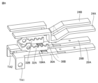
- FIG. FIG. 4 is a diagram illustrating a main part of commutation section 10 according to the first embodiment;
- FIG. 10 is a diagram illustrating a main part of commutation section 10A according to the second embodiment;
- FIG. 11 is a diagram illustrating a main part of commutation portion 10B according to the third embodiment;
- FIG. 20 is a diagram illustrating a main part of second contact 18#A according to the fourth embodiment;
- FIG. 20 is a diagram illustrating a main part of commutation portion 10C according to a modification of the fourth embodiment;
- FIG. 11 is a circuit configuration diagram of a switchgear 1A according to Embodiment 5;
- FIG. 11 is a circuit configuration diagram of a switchgear 1B according to a modification of the
- Embodiment 1A and 1B are diagrams illustrating an external configuration of a switchgear 1 according to Embodiment 1.
- the switchgear 1 includes an accident detection section 4, a first contact 6, a commutation section 10 including a second contact, a current limiting resistor 2 (2A, 2B) and a contact pressure spring 5B.
- the current-limiting resistance 2 includes current-limiting resistances 2A and 2B.
- Current-limiting resistors 2A and 2B are connected in series by a resistor-connecting conductor 3.
- FIG. 1 A resistor-connecting conductor 3.
- the accident detector 4 is arranged on a common conductor where the parallel circuits join.
- the accident detection unit 4 detects the magnetic flux density generated by the current in the conductor, and is composed of a movable iron core that is driven when a current exceeding a certain level flows, and a fixed iron core. Concatenated.
- the first contact 6 is adapted to be driven together with the movable core.
- the accident detection unit 4 drives the movable iron core when an abnormality occurs in the parallel circuit and the current flowing through the conductor increases. This opens the first contact and transfers the current to the commutation section 10 .
- FIG. 2 is a circuit configuration diagram of the switchgear 1 according to the first embodiment.
- switchgear 1 includes a first contact 6 and an accident detector 4 for controlling the switching pole operation of first contact 6 .
- the commutation part 10 is connected in parallel with the first contact 6 .
- a current limiting resistor 2 is connected in parallel with the first contact 6 and the commutation section 10 .
- the commutation section 10 includes a discharge switch 12 , a discharge resistor 14 , an opening operation section 16 and a second contact 18 .
- the second contact 18 is connected in parallel with the first contact 6 .
- the opening operation unit 16 maintains the open state of the second contact 18 .
- the discharge switch 12 is arranged in parallel with the second contact 18, becomes energized only when discharge occurs, and has a function of increasing resistance. Specifically, the discharge switch 12 is connected in series with the discharge resistor 14 and in parallel with the second contact 18 . The discharge switch 12 is energized only when an arc discharge occurs.
- the second contact 18 is opened when the second contact 18 is energized, and the arc discharge generated when the second contact 18 is opened is driven to the discharge switch 12, whereby the current path is from the second contact 18 to the discharge switch 12. switch to.
- FIG. 3 is a diagram illustrating a main part of commutation section 10 according to the first embodiment.
- the commutation portion 10 includes a housing 22, terminals TA, TB, TC, an opening operating portion 16, a second contact 18, a contact pressure spring 20, an arc Runners 24 , 28 and arc extinguishing member 26 are included.
- the second contact 18 is composed of a pair of long axis-shaped current-carrying electrodes facing each other, and includes a fixed contact 30 with a fixed contact and a movable contact 32 with a movable contact that contacts and does not contact the fixed contact. including.
- the second contact 18 is connected to a connection node between the accident detector 4 and the first contact 6 via the terminal TA.
- the movable contactor 32 is connected to the contact pressure spring 20 and is normally pressed to contact the fixed contactor 30 and conduct.
- the opening operation unit 16 is connected to the movable contactor 32 to open the second contact.
- the opening operation unit 16 is connected to a connection node between the accident detection unit 4 and the first contact 6 via a terminal TB.
- Arc runners 24 and 28 are arranged at the top and bottom of housing 22 .
- Arc runner 24 is connected to movable contact 32 .
- Arc runner 28 is connected to fixed contact 30 .
- Arc-extinguishing member 26 is provided between arc runner 24 and arc runner 28 .
- the second contact 18 is normally closed by the contact pressure spring 20, but the first contact 6 is opened and current flows to the circuit having the second contact 18.
- a current path is formed from the terminal TA through the fixed contact 30, the movable contact 32, and the terminal TB.
- the fixed contact 30 and the movable contact 32 are each composed of a long-axis-shaped current-carrying electrode pair facing each other, and when the second contact 18 is energized, the current-carrying electrode pair respectively flows in opposite directions. A repulsive force is generated between the current-carrying electrodes. That is, when the second contact 18 is energized, the second contact 18 is automatically and rapidly separated by the repulsive force.
- Electromagnetic force is generated inside the arc discharge due to the contribution of the magnetic field generated between the fixed contact 30 and the movable contact 32, and the arc discharge is driven to the discharge switch 12 side.
- the discharge switch 12 is connected to the arc runner 24 and the arc runner 28, the driven arc discharge is commutated to the arc runner 24 and the arc runner 28, and driven toward the tip side of the arc runner 24 and the arc runner 28. decompressed.
- the discharge resistance increases as the arc discharge extends, and the current is suppressed.
- An arc-extinguishing member 26 is provided between the arc runner 24 and the arc runner 28, and the arc-extinguishing member 26 such as an arc-extinguishing plate provided at the extension of the arc discharge can increase the discharge resistance. be.
- the configuration of the commutation section 10 according to the first embodiment makes it possible to increase the electric resistance in the circuit without using a resistive element such as a PTC element. It is possible to exhibit a current suppressing function even at a large current of several kA to several tens of kA or more without being restricted by the current used by the PTC element.
- the switchgear 1 can be realized with a simple structure without increasing the size.
- the switchgear 1 according to Embodiment 1 has a configuration in which a current-limiting resistor 2 is provided in parallel with the first contact 6 .
- a current-limiting resistor 2 By providing the current-limiting resistor 2 in parallel, part of the current is commutated to the current-limiting resistor 2 as the electrical resistance of the discharge switch 12 increases, so that the wear of the discharge switch 12 due to arc discharge can be further suppressed. can be done.
- the switchgear 1 when the switchgear 1 according to the first embodiment cooperates with another circuit breaker or switch to break the circuit, the current-limiting resistor 2 continues to operate until the other circuit breaker or switch is opened. It is possible to maintain the current limiting effect for a long time.
- the commutation unit 10 includes an opening operation unit 16 that opens the second contact 18 .
- the opening operation unit 16 includes a connecting part 160 connected to the movable contact 32, a movable iron core 162, a fixed iron core 164, and a conducting conductor 166.
- the opening operation unit 16 keeps the second contact 18 open. Immediately after the second contact 18 is energized, the contacts are quickly separated, but the opening operation unit 16 drives the movable contact 32 even when the electromagnetic force acting on the movable contact 32 is reduced. Thus, it is possible to maintain the open state of the second contact 18 .
- the opening operation part 16 may be composed of an electromagnet with a plurality of iron cores.
- the movable iron core 164 is connected to the movable contactor 32 via the connection part 160 .
- the current flows through the current limiting resistor 2 as a shunt to the opening operation portion 16.
- the attraction force it is possible to increase the opening speed of the second contact 18 .
- the second contact 18 can be continuously held in the open state. can. As a result, it is possible to suppress the reduction in the opening interval of the second contact 18 and to easily secure the insulating state between the contacts.
- the contact opening operation unit 16 or the accident detection unit 4 may receive a power signal from a system different from the system to be opened and closed.
- the opening operation unit 16 or the accident detection unit 4 opens the second contact 18 or the first contact 6 when receiving another power signal.
- a control power supply is provided separately, and the control power supply is connected to the opening operation unit 16 or the accident detection unit 4, and the power of the control power supply is used to connect the second contact 18 or the first contact. contact 6 may be opened.
- sensor information such as a current sensor (not shown), and if an abnormality is determined, power is supplied from the control power supply to start the operation of the switchgear based on various information. can be Other sensors may be used instead of current sensors.
- the first contact 6 or the second contact 18 is opened in advance by the power signal.
- Polar operation It is possible to configure a circuit through the current limiting resistor 2 of the switchgear 1 . As a result, the load circuit can be connected while the inrush current is suppressed by the current limiting resistor 2 .
- the second contact 18 by allowing the second contact 18 to be opened and closed by a power signal from the different system, it is possible to receive an accident cancellation command from a device other than the switchgear of the present disclosure. judgment becomes unnecessary. As a result, even when a current-limiting resistor set with a large electrical resistance value is installed together and the current after the current-limiting becomes extremely small, the open contact holding of the second contact 18 can be stably controlled. It is possible.
- FIG. 4 is a diagram illustrating a main part of commutation section 10A according to the second embodiment. Referring to FIG. 4(A), it differs from the commutation section 10 in that the opening operation section 16 is replaced with an opening operation section 16A. Other configurations are the same as those described with reference to FIG. 3, and detailed description thereof will not be repeated.
- the opening operation section 16A is composed of a single or a plurality of coils.
- the magnetic flux generated by the coil is used to open the second contact 18 .
- the opening operation part 16A By configuring the opening operation part 16A with a coil, a reactance is generated in the circuit when current passes through the coil, and this makes it possible to limit the current to a small value.
- a high magnetic flux density is generated around the coil due to the number of coil turns and passing current. It is possible to keep the movable contact 32 open by generating an electromagnetic force or the like using the magnetic flux density.
- the opening operation part 16A can increase the opening speed of the second contact 18 by using the electromagnetic force before the circuit having the discharge switch 12 becomes energized.
- the coils are composed of a plurality of coils
- one coil is electrically connected to the movable contact 32 and the arc runner 24, and the other coils are connected to a separate power source.
- the opening operation of the movable contactor 32 may be performed by a power signal of another system.
- the opening operation unit 16A uses an iron core as in the first embodiment, arranges the coil 168 wound around the fixed iron core 164, and generates an electric current from the coil 168. By operating the movable core 162 using the magnetic flux, it is also possible to open or hold the second contact 18 .
- FIG. 5 is a diagram illustrating a main part of commutation portion 10B according to the third embodiment.
- the contact pressure spring 20 is different in that additional parts are added.
- Other configurations are the same as those described with reference to FIG. 3, and detailed description thereof will not be repeated.
- the commutation portion 10B further includes a spring accumulating component 21 and a contact pressure adjusting mechanism 23 .
- the contact pressure spring 20 is provided with a spring accumulating component 21 and a contact pressure adjustment mechanism 23 .
- the contact pressure adjusting mechanism 23 is provided with a spring accumulating component 21 capable of adjusting the amount of energization of the contact pressure spring 20 on the opposite side of the contact pressure spring 20 from the arrangement position of the movable contactor 32 .
- a spring accumulating component 21 capable of adjusting the amount of energization of the contact pressure spring 20 on the opposite side of the contact pressure spring 20 from the arrangement position of the movable contactor 32 .
- the time difference between the opening of the first contact 6 and the opening of the second contact 18 can be adjusted.
- the second contact 18 is allowed to open after the current is completely transferred to the circuit with the contact.
- the time until the arc discharge that occurs when the first contact 6 opens when the second contact 18 opens before the current is transferred from the first contact 6 to the circuit with the second contact 18 is extinguished is prolonged and the first contact 6 is likely to be worn, but according to Embodiment 3, it is possible to prevent the arc discharge that occurs when the first contact 6 is opened from being prolonged. .
- FIG. 6 is a diagram illustrating a main part of second contact 18#A according to the fourth embodiment. 6, the difference is that the second contact 18 is replaced with a second contact 18#A.
- Other configurations are the same as those of the other embodiments.
- the second contact 18#A is formed in a U-shape. Specifically, the second contact 18#A includes a plurality of fixed contacts and a plurality of movable contacts provided corresponding to the plurality of fixed contacts, respectively.
- the second contact 18#A includes fixed contacts 30A, 30B and movable contacts 32A, 32B. It is composed of contact pairs of fixed contacts and movable contacts, and a plurality of fixed contacts and movable contacts are connected in series.
- the number of contact pairs of the second contact 18#A may be configured to have more than two pairs in series.
- arc runners 28A and 28B are provided corresponding to the fixed contacts 30A and 30B, respectively.
- Arc runners 24A and 24B are provided corresponding to the movable contacts 32A and 32B, respectively.
- a plurality of arc discharges are driven to the discharge switch 12 side by electromagnetic force.
- the discharge switch 12 is connected to the arc runners 24A, 24B and the arc runners 28A, 28B, and the driven arc discharge is driven and extended toward the tip side of the arc runners 24A, 24B and the arc runners 28A, 28B. be done.
- the arc discharge generated between the arc runners 24A, 24B and the arc runners 28A, 28B increases the discharge resistance as the arc discharge extends, and the current is suppressed.
- the electrode drop voltage increases with the number of arc discharges that occur, so it is possible to further exert the effect of limiting the circuit current.
- Arc-extinguishing members may be provided between the arc runners 24A, 24B and the arc runners 28A, 28B.
- FIG. 7 is a diagram illustrating a main part of a commutation section 10C according to a modification of the fourth embodiment. Referring to FIG. 7, it differs from commutation section 10 in that second contact 18 is replaced with second contact 18#B.
- the second contact 18#B is formed not in a U-shape but in a straight line.
- the second contact 18#B includes a plurality of fixed contacts and a plurality of movable contacts provided corresponding to the plurality of fixed contacts.
- the second contact 18#B includes fixed contacts 30A, 30B and movable contacts 32A, 32B. It is composed of contact pairs of fixed contacts and movable contacts, and a plurality of fixed contacts and movable contacts are connected in series. The movable contacts 32A, 32B are pressed against the fixed contacts 30A, 30B by contact pressure springs 20A, 20B, respectively.
- the number of contact pairs of the second contact 18#B may be configured to have more than two pairs in series.
- a fixed contact 30A is arranged on the right side and a fixed contact 30B is arranged on the left side.
- Arc runners 28A and 28B are provided corresponding to the fixed contacts 30A and 30B, respectively.
- Arc runners 24A and 24B are provided corresponding to the movable contacts 32A and 32B, respectively.
- An arc-extinguishing member 26A is provided between the arc runner 24A and the arc runner 28A.
- An arc extinguishing member 26B is provided between the arc runner 24B and the arc runner 28B.
- Embodiment 5 a method for stabilizing the commutation control of the current from the first contact 6 to the commutation section 10 will be described.
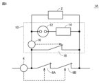
- FIG. 8 is a circuit configuration diagram of a switchgear 1A according to Embodiment 5.
- FIG. 8 switchgear 1A differs from switchgear 1 in that first contact 6 is replaced with first contact 6A.
- the first contact 6A has two contact pairs arranged in series.
- the contact pair does not have to be two points in series, and the contact pair of the first contact 6A should be composed of a contact pair having a larger number of series than the contact pairs of the second contact 18.
- the plurality of contacts Since the electrode drop voltage occurring on the first contact 6A having a pair is always higher than the electrode drop voltage occurring on the second contact 18, the voltage from the first contact 6A having a plurality of contact pairs to the commutating portion 10 It is possible to suppress the decrease in the commutation speed of the current and perform stable commutation control. Therefore, the duration of the arc discharge that occurs when the first contact 6A is opened can be shortened, and the wear of the first contact 6A can be suppressed.
- the contact can be stably switched due to the difference in the electrode drop voltage. Since it is possible to control the current, it is possible to accelerate the current transfer from the second contact 18 to the discharge switch 12, and by increasing the discharge resistance at an early stage, the circuit current can be quickly limited immediately after the occurrence of an abnormality. It is also possible to
- FIG. 9 is a circuit configuration diagram of a switchgear 1B according to a modification of the fifth embodiment.
- switchgear 1B differs from switchgear 1 in that first contact 6 is replaced with first contact 6B.
- the first contact 6B has a configuration in which a plurality of contact pairs are provided in parallel. It should be noted that it is not necessary to provide two contact pairs in parallel, and a plurality of contact points may be provided in parallel.
- the plurality of contact points may be configured such that a plurality of movable electrodes having contacts can be opened and closed, or a single movable electrode may be provided with a contact having a shape having a plurality of contact points.
- the contact resistance at the contact point is inversely proportional to the square root of the contact pressure load based on the Holm equation, a plurality of contact points are provided to distribute the load at each contact point. It is possible to suppress the contact resistance to be small by arranging them in such a way that they are aligned with each other.
- the material and shape of the contact that finally separates it is possible to have the following features. For example, by using a material with a high melting point as the material of the contact that is opened last, it is possible to reduce melting damage when arc discharge occurs and prevent deterioration of the first contact 6B during opening and closing. .
- the contact that opens last by limiting the opposing area of the contact pair to a small size, in addition to the electrode drop voltage at the time of contact opening, the cross-sectional area of the arc discharge can be narrowed down. The resulting voltage drop can be further increased.
- the commutation control of the current from the first contact 6B to the commutation section 10 can also be stabilized.
- the configuration illustrated as the above-described embodiment is an example of the configuration of the present disclosure, and can be combined with another known technique. , can also be modified and configured. Further, in the above-described embodiment, the processing and configuration described in other embodiments may be appropriately adopted and implemented.
- 1, 1A, 1B switchgear 2, 2A, 2B current-limiting resistor, 3 resistor connection conductor, 4 accident detection part, 5A conductor, 5B, 20, 20A, 20B contact pressure spring, 6, 6A, 6B first contact , 7, 22 housing, 10, 10A, 10B, 10C commutation part, 12 discharge switch, 14 discharge resistance, 16, 16A opening operation part, 18 second contact, 21 spring accumulating part, 23 contact pressure adjustment Mechanism, 24, 24A, 24B, 28, 28A, 28B Arc runner, 26, 26A, 26B Arc extinguishing member, 30, 30A, 30B Fixed contact, 32, 32A, 32B Movable contact.
Landscapes
- Arc-Extinguishing Devices That Are Switches (AREA)
- Breakers (AREA)
Priority Applications (5)
| Application Number | Priority Date | Filing Date | Title |
|---|---|---|---|
| CN202180104289.XA CN118382902A (zh) | 2021-12-27 | 2021-12-27 | 开闭装置 |
| US18/718,806 US20250046547A1 (en) | 2021-12-27 | 2021-12-27 | Switching device |
| JP2023570532A JP7599587B2 (ja) | 2021-12-27 | 2021-12-27 | 開閉装置 |
| EP21969929.5A EP4459654A4 (en) | 2021-12-27 | 2021-12-27 | SWITCHING DEVICE |
| PCT/JP2021/048644 WO2023127045A1 (ja) | 2021-12-27 | 2021-12-27 | 開閉装置 |
Applications Claiming Priority (1)
| Application Number | Priority Date | Filing Date | Title |
|---|---|---|---|
| PCT/JP2021/048644 WO2023127045A1 (ja) | 2021-12-27 | 2021-12-27 | 開閉装置 |
Publications (1)
| Publication Number | Publication Date |
|---|---|
| WO2023127045A1 true WO2023127045A1 (ja) | 2023-07-06 |
Family
ID=86998352
Family Applications (1)
| Application Number | Title | Priority Date | Filing Date |
|---|---|---|---|
| PCT/JP2021/048644 Ceased WO2023127045A1 (ja) | 2021-12-27 | 2021-12-27 | 開閉装置 |
Country Status (5)
| Country | Link |
|---|---|
| US (1) | US20250046547A1 (https=) |
| EP (1) | EP4459654A4 (https=) |
| JP (1) | JP7599587B2 (https=) |
| CN (1) | CN118382902A (https=) |
| WO (1) | WO2023127045A1 (https=) |
Citations (5)
| Publication number | Priority date | Publication date | Assignee | Title |
|---|---|---|---|---|
| JPS504996Y1 (https=) * | 1969-05-15 | 1975-02-12 | ||
| US5899323A (en) * | 1998-05-07 | 1999-05-04 | Eaton Corporation | Electrical switching apparatus with contact finger guide |
| JP2001515337A (ja) | 1997-08-29 | 2001-09-18 | タイコ・エレクトロニクス・コーポレイション | Ptcの作動耐久性が改良された過電流保護回路 |
| JP2013140767A (ja) * | 2011-12-07 | 2013-07-18 | Mitsubishi Electric Corp | 開閉器 |
| WO2017183679A1 (ja) * | 2016-04-22 | 2017-10-26 | 三菱電機株式会社 | 回路遮断器の接触子装置、およびこの接触子装置を用いた回路遮断器 |
Family Cites Families (1)
| Publication number | Priority date | Publication date | Assignee | Title |
|---|---|---|---|---|
| KR101521545B1 (ko) * | 2013-10-07 | 2015-05-19 | 한국전기연구원 | 고압 직류 전류 차단 장치 및 방법 |
-
2021
- 2021-12-27 EP EP21969929.5A patent/EP4459654A4/en not_active Withdrawn
- 2021-12-27 US US18/718,806 patent/US20250046547A1/en active Pending
- 2021-12-27 CN CN202180104289.XA patent/CN118382902A/zh not_active Withdrawn
- 2021-12-27 WO PCT/JP2021/048644 patent/WO2023127045A1/ja not_active Ceased
- 2021-12-27 JP JP2023570532A patent/JP7599587B2/ja active Active
Patent Citations (5)
| Publication number | Priority date | Publication date | Assignee | Title |
|---|---|---|---|---|
| JPS504996Y1 (https=) * | 1969-05-15 | 1975-02-12 | ||
| JP2001515337A (ja) | 1997-08-29 | 2001-09-18 | タイコ・エレクトロニクス・コーポレイション | Ptcの作動耐久性が改良された過電流保護回路 |
| US5899323A (en) * | 1998-05-07 | 1999-05-04 | Eaton Corporation | Electrical switching apparatus with contact finger guide |
| JP2013140767A (ja) * | 2011-12-07 | 2013-07-18 | Mitsubishi Electric Corp | 開閉器 |
| WO2017183679A1 (ja) * | 2016-04-22 | 2017-10-26 | 三菱電機株式会社 | 回路遮断器の接触子装置、およびこの接触子装置を用いた回路遮断器 |
Non-Patent Citations (1)
| Title |
|---|
| See also references of EP4459654A4 |
Also Published As
| Publication number | Publication date |
|---|---|
| EP4459654A1 (en) | 2024-11-06 |
| US20250046547A1 (en) | 2025-02-06 |
| JPWO2023127045A1 (https=) | 2023-07-06 |
| JP7599587B2 (ja) | 2024-12-13 |
| EP4459654A4 (en) | 2025-02-26 |
| CN118382902A (zh) | 2024-07-23 |
Similar Documents
| Publication | Publication Date | Title |
|---|---|---|
| JP5793019B2 (ja) | 消弧装置および開閉器 | |
| US5638038A (en) | Switch including breaker | |
| CN102339677B (zh) | 触点保护电路和包括该触点保护电路的高压继电器 | |
| US6831533B2 (en) | Electromagnetic relay | |
| US11710606B2 (en) | Dual parallel moveable electrical contacts/relays | |
| CN113574624A (zh) | 保护系统 | |
| JP2009268214A (ja) | 電源機器モジュール | |
| US9837232B2 (en) | Electromechanical circuit breaker | |
| JP7599587B2 (ja) | 開閉装置 | |
| US10529522B2 (en) | Circuit breaker | |
| US5777286A (en) | Electric device having separable contacts with arc switching | |
| US4516005A (en) | Sequenced intermittent blowout coil controller | |
| JP2002521801A (ja) | 短絡防護装置 | |
| JP6105231B2 (ja) | 開閉器 | |
| CN210956581U (zh) | 一种具有分流电阻的微型电磁铁及其应用的微型断路器 | |
| CN111696795B (zh) | 用于在电路中建立或断开电流的电气设备 | |
| US6665157B2 (en) | Apparatus for interrupting an electrical circuit | |
| US20250118509A1 (en) | Switchgear and method for controlling switchgear | |
| JPWO2023127045A5 (https=) | ||
| US3454831A (en) | Quick-opening,low cost,current limiting circuit breaker | |
| JP7593302B2 (ja) | 回路遮断器 | |
| JP7774257B2 (ja) | 接点ランニング装置 | |
| JP4214494B2 (ja) | 電動モータを制御する装置 | |
| US20020012214A1 (en) | Method for interrupting a current-carrying path | |
| CN118571673A (zh) | 适用于大功率电路的电接触器、包括集成至少一个这种电接触器的电路的飞行器 |
Legal Events
| Date | Code | Title | Description |
|---|---|---|---|
| 121 | Ep: the epo has been informed by wipo that ep was designated in this application |
Ref document number: 21969929 Country of ref document: EP Kind code of ref document: A1 |
|
| ENP | Entry into the national phase |
Ref document number: 2023570532 Country of ref document: JP Kind code of ref document: A |
|
| WWE | Wipo information: entry into national phase |
Ref document number: 202180104289.X Country of ref document: CN |
|
| WWE | Wipo information: entry into national phase |
Ref document number: 202427044363 Country of ref document: IN |
|
| WWE | Wipo information: entry into national phase |
Ref document number: 18718806 Country of ref document: US |
|
| NENP | Non-entry into the national phase |
Ref country code: DE |
|
| ENP | Entry into the national phase |
Ref document number: 2021969929 Country of ref document: EP Effective date: 20240729 |
|
| WWW | Wipo information: withdrawn in national office |
Ref document number: 2021969929 Country of ref document: EP |