WO2023127045A1 - 開閉装置 - Google Patents
開閉装置 Download PDFInfo
- Publication number
- WO2023127045A1 WO2023127045A1 PCT/JP2021/048644 JP2021048644W WO2023127045A1 WO 2023127045 A1 WO2023127045 A1 WO 2023127045A1 JP 2021048644 W JP2021048644 W JP 2021048644W WO 2023127045 A1 WO2023127045 A1 WO 2023127045A1
- Authority
- WO
- WIPO (PCT)
- Prior art keywords
- contact
- movable
- arc
- current
- fixed
- Prior art date
Links
Images


Classifications
-
- H—ELECTRICITY
- H01—ELECTRIC ELEMENTS
- H01H—ELECTRIC SWITCHES; RELAYS; SELECTORS; EMERGENCY PROTECTIVE DEVICES
- H01H33/00—High-tension or heavy-current switches with arc-extinguishing or arc-preventing means
- H01H33/02—Details
- H01H33/04—Means for extinguishing or preventing arc between current-carrying parts
- H01H33/12—Auxiliary contacts on to which the arc is transferred from the main contacts
-
- H—ELECTRICITY
- H01—ELECTRIC ELEMENTS
- H01H—ELECTRIC SWITCHES; RELAYS; SELECTORS; EMERGENCY PROTECTIVE DEVICES
- H01H33/00—High-tension or heavy-current switches with arc-extinguishing or arc-preventing means
- H01H33/02—Details
- H01H33/04—Means for extinguishing or preventing arc between current-carrying parts
- H01H33/20—Means for extinguishing or preventing arc between current-carrying parts using arcing horns
Definitions
- the present disclosure relates to switching devices such as switches, switches, circuit breakers, electromagnetic contactors, and relays that open and close electric circuits.
- switchgear in addition to closing or opening the electric circuit with electric contacts, it safely opens the electric circuit even in the event of an abnormality such as a short circuit or overcurrent.
- a first contact, a second contact provided in parallel with the first contact, and a second contact provided in series with the second contact are provided in order to prevent an increase in current when an abnormality occurs.
- a current limiting element provided in parallel with the first contact and the second contact. The switching device sequentially opens the first contact and the second contact when an abnormality occurs.
- the switchgear conducts current with little resistance loss at the first contact under normal conditions, and when an abnormality occurs, the current flows through the circuit having the second contact and the PTC element as a step before transferring the current to the current limiting element. to migrate. As a result, it is possible to stabilize the transfer of current to the current limiting element while preventing the first contact from being damaged by arc discharge, thereby preventing an increase in current (see, for example, Patent Document 1).
- the present disclosure is intended to solve the above problems, and aims to provide a switchgear capable of preventing contact damage in a simple manner.
- the switchgear includes a first contact, a second contact provided in parallel with the first contact, and a energized state only when a discharge occurs, provided in parallel with the second contact. and an accident detector that opens the first contact when an accident is detected.
- the discharge switch has a resistance rise function. The second contact is opened when it becomes energized, and the current path is switched from the second contact to the circuit having the discharge switch by driving the discharge generated when the second contact is opened to the discharge switch.
- a switchgear according to the present disclosure can prevent contact damage in a simple manner.
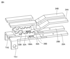
- FIG. 2A and 2B are diagrams illustrating an external configuration of the opening/closing device 1 according to the first embodiment;
- FIG. 1 is a circuit configuration diagram of switchgear 1 according to Embodiment 1.
- FIG. FIG. 4 is a diagram illustrating a main part of commutation section 10 according to the first embodiment;
- FIG. 10 is a diagram illustrating a main part of commutation section 10A according to the second embodiment;
- FIG. 11 is a diagram illustrating a main part of commutation portion 10B according to the third embodiment;
- FIG. 20 is a diagram illustrating a main part of second contact 18#A according to the fourth embodiment;
- FIG. 20 is a diagram illustrating a main part of commutation portion 10C according to a modification of the fourth embodiment;
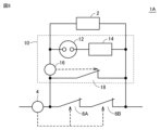
- FIG. 11 is a circuit configuration diagram of a switchgear 1A according to Embodiment 5;
- FIG. 11 is a circuit configuration diagram of a switchgear 1B according to a modification of the
- Embodiment 1A and 1B are diagrams illustrating an external configuration of a switchgear 1 according to Embodiment 1.
- the switchgear 1 includes an accident detection section 4, a first contact 6, a commutation section 10 including a second contact, a current limiting resistor 2 (2A, 2B) and a contact pressure spring 5B.
- the current-limiting resistance 2 includes current-limiting resistances 2A and 2B.
- Current-limiting resistors 2A and 2B are connected in series by a resistor-connecting conductor 3.
- FIG. 1 A resistor-connecting conductor 3.
- the accident detector 4 is arranged on a common conductor where the parallel circuits join.
- the accident detection unit 4 detects the magnetic flux density generated by the current in the conductor, and is composed of a movable iron core that is driven when a current exceeding a certain level flows, and a fixed iron core. Concatenated.
- the first contact 6 is adapted to be driven together with the movable core.
- the accident detection unit 4 drives the movable iron core when an abnormality occurs in the parallel circuit and the current flowing through the conductor increases. This opens the first contact and transfers the current to the commutation section 10 .
- FIG. 2 is a circuit configuration diagram of the switchgear 1 according to the first embodiment.
- switchgear 1 includes a first contact 6 and an accident detector 4 for controlling the switching pole operation of first contact 6 .
- the commutation part 10 is connected in parallel with the first contact 6 .
- a current limiting resistor 2 is connected in parallel with the first contact 6 and the commutation section 10 .
- the commutation section 10 includes a discharge switch 12 , a discharge resistor 14 , an opening operation section 16 and a second contact 18 .
- the second contact 18 is connected in parallel with the first contact 6 .
- the opening operation unit 16 maintains the open state of the second contact 18 .
- the discharge switch 12 is arranged in parallel with the second contact 18, becomes energized only when discharge occurs, and has a function of increasing resistance. Specifically, the discharge switch 12 is connected in series with the discharge resistor 14 and in parallel with the second contact 18 . The discharge switch 12 is energized only when an arc discharge occurs.
- the second contact 18 is opened when the second contact 18 is energized, and the arc discharge generated when the second contact 18 is opened is driven to the discharge switch 12, whereby the current path is from the second contact 18 to the discharge switch 12. switch to.
- FIG. 3 is a diagram illustrating a main part of commutation section 10 according to the first embodiment.
- the commutation portion 10 includes a housing 22, terminals TA, TB, TC, an opening operating portion 16, a second contact 18, a contact pressure spring 20, an arc Runners 24 , 28 and arc extinguishing member 26 are included.
- the second contact 18 is composed of a pair of long axis-shaped current-carrying electrodes facing each other, and includes a fixed contact 30 with a fixed contact and a movable contact 32 with a movable contact that contacts and does not contact the fixed contact. including.
- the second contact 18 is connected to a connection node between the accident detector 4 and the first contact 6 via the terminal TA.
- the movable contactor 32 is connected to the contact pressure spring 20 and is normally pressed to contact the fixed contactor 30 and conduct.
- the opening operation unit 16 is connected to the movable contactor 32 to open the second contact.
- the opening operation unit 16 is connected to a connection node between the accident detection unit 4 and the first contact 6 via a terminal TB.
- Arc runners 24 and 28 are arranged at the top and bottom of housing 22 .
- Arc runner 24 is connected to movable contact 32 .
- Arc runner 28 is connected to fixed contact 30 .
- Arc-extinguishing member 26 is provided between arc runner 24 and arc runner 28 .
- the second contact 18 is normally closed by the contact pressure spring 20, but the first contact 6 is opened and current flows to the circuit having the second contact 18.
- a current path is formed from the terminal TA through the fixed contact 30, the movable contact 32, and the terminal TB.
- the fixed contact 30 and the movable contact 32 are each composed of a long-axis-shaped current-carrying electrode pair facing each other, and when the second contact 18 is energized, the current-carrying electrode pair respectively flows in opposite directions. A repulsive force is generated between the current-carrying electrodes. That is, when the second contact 18 is energized, the second contact 18 is automatically and rapidly separated by the repulsive force.
- Electromagnetic force is generated inside the arc discharge due to the contribution of the magnetic field generated between the fixed contact 30 and the movable contact 32, and the arc discharge is driven to the discharge switch 12 side.
- the discharge switch 12 is connected to the arc runner 24 and the arc runner 28, the driven arc discharge is commutated to the arc runner 24 and the arc runner 28, and driven toward the tip side of the arc runner 24 and the arc runner 28. decompressed.
- the discharge resistance increases as the arc discharge extends, and the current is suppressed.
- An arc-extinguishing member 26 is provided between the arc runner 24 and the arc runner 28, and the arc-extinguishing member 26 such as an arc-extinguishing plate provided at the extension of the arc discharge can increase the discharge resistance. be.
- the configuration of the commutation section 10 according to the first embodiment makes it possible to increase the electric resistance in the circuit without using a resistive element such as a PTC element. It is possible to exhibit a current suppressing function even at a large current of several kA to several tens of kA or more without being restricted by the current used by the PTC element.
- the switchgear 1 can be realized with a simple structure without increasing the size.
- the switchgear 1 according to Embodiment 1 has a configuration in which a current-limiting resistor 2 is provided in parallel with the first contact 6 .
- a current-limiting resistor 2 By providing the current-limiting resistor 2 in parallel, part of the current is commutated to the current-limiting resistor 2 as the electrical resistance of the discharge switch 12 increases, so that the wear of the discharge switch 12 due to arc discharge can be further suppressed. can be done.
- the switchgear 1 when the switchgear 1 according to the first embodiment cooperates with another circuit breaker or switch to break the circuit, the current-limiting resistor 2 continues to operate until the other circuit breaker or switch is opened. It is possible to maintain the current limiting effect for a long time.
- the commutation unit 10 includes an opening operation unit 16 that opens the second contact 18 .
- the opening operation unit 16 includes a connecting part 160 connected to the movable contact 32, a movable iron core 162, a fixed iron core 164, and a conducting conductor 166.
- the opening operation unit 16 keeps the second contact 18 open. Immediately after the second contact 18 is energized, the contacts are quickly separated, but the opening operation unit 16 drives the movable contact 32 even when the electromagnetic force acting on the movable contact 32 is reduced. Thus, it is possible to maintain the open state of the second contact 18 .
- the opening operation part 16 may be composed of an electromagnet with a plurality of iron cores.
- the movable iron core 164 is connected to the movable contactor 32 via the connection part 160 .
- the current flows through the current limiting resistor 2 as a shunt to the opening operation portion 16.
- the attraction force it is possible to increase the opening speed of the second contact 18 .
- the second contact 18 can be continuously held in the open state. can. As a result, it is possible to suppress the reduction in the opening interval of the second contact 18 and to easily secure the insulating state between the contacts.
- the contact opening operation unit 16 or the accident detection unit 4 may receive a power signal from a system different from the system to be opened and closed.
- the opening operation unit 16 or the accident detection unit 4 opens the second contact 18 or the first contact 6 when receiving another power signal.
- a control power supply is provided separately, and the control power supply is connected to the opening operation unit 16 or the accident detection unit 4, and the power of the control power supply is used to connect the second contact 18 or the first contact. contact 6 may be opened.
- sensor information such as a current sensor (not shown), and if an abnormality is determined, power is supplied from the control power supply to start the operation of the switchgear based on various information. can be Other sensors may be used instead of current sensors.
- the first contact 6 or the second contact 18 is opened in advance by the power signal.
- Polar operation It is possible to configure a circuit through the current limiting resistor 2 of the switchgear 1 . As a result, the load circuit can be connected while the inrush current is suppressed by the current limiting resistor 2 .
- the second contact 18 by allowing the second contact 18 to be opened and closed by a power signal from the different system, it is possible to receive an accident cancellation command from a device other than the switchgear of the present disclosure. judgment becomes unnecessary. As a result, even when a current-limiting resistor set with a large electrical resistance value is installed together and the current after the current-limiting becomes extremely small, the open contact holding of the second contact 18 can be stably controlled. It is possible.
- FIG. 4 is a diagram illustrating a main part of commutation section 10A according to the second embodiment. Referring to FIG. 4(A), it differs from the commutation section 10 in that the opening operation section 16 is replaced with an opening operation section 16A. Other configurations are the same as those described with reference to FIG. 3, and detailed description thereof will not be repeated.
- the opening operation section 16A is composed of a single or a plurality of coils.
- the magnetic flux generated by the coil is used to open the second contact 18 .
- the opening operation part 16A By configuring the opening operation part 16A with a coil, a reactance is generated in the circuit when current passes through the coil, and this makes it possible to limit the current to a small value.
- a high magnetic flux density is generated around the coil due to the number of coil turns and passing current. It is possible to keep the movable contact 32 open by generating an electromagnetic force or the like using the magnetic flux density.
- the opening operation part 16A can increase the opening speed of the second contact 18 by using the electromagnetic force before the circuit having the discharge switch 12 becomes energized.
- the coils are composed of a plurality of coils
- one coil is electrically connected to the movable contact 32 and the arc runner 24, and the other coils are connected to a separate power source.
- the opening operation of the movable contactor 32 may be performed by a power signal of another system.
- the opening operation unit 16A uses an iron core as in the first embodiment, arranges the coil 168 wound around the fixed iron core 164, and generates an electric current from the coil 168. By operating the movable core 162 using the magnetic flux, it is also possible to open or hold the second contact 18 .
- FIG. 5 is a diagram illustrating a main part of commutation portion 10B according to the third embodiment.
- the contact pressure spring 20 is different in that additional parts are added.
- Other configurations are the same as those described with reference to FIG. 3, and detailed description thereof will not be repeated.
- the commutation portion 10B further includes a spring accumulating component 21 and a contact pressure adjusting mechanism 23 .
- the contact pressure spring 20 is provided with a spring accumulating component 21 and a contact pressure adjustment mechanism 23 .
- the contact pressure adjusting mechanism 23 is provided with a spring accumulating component 21 capable of adjusting the amount of energization of the contact pressure spring 20 on the opposite side of the contact pressure spring 20 from the arrangement position of the movable contactor 32 .
- a spring accumulating component 21 capable of adjusting the amount of energization of the contact pressure spring 20 on the opposite side of the contact pressure spring 20 from the arrangement position of the movable contactor 32 .
- the time difference between the opening of the first contact 6 and the opening of the second contact 18 can be adjusted.
- the second contact 18 is allowed to open after the current is completely transferred to the circuit with the contact.
- the time until the arc discharge that occurs when the first contact 6 opens when the second contact 18 opens before the current is transferred from the first contact 6 to the circuit with the second contact 18 is extinguished is prolonged and the first contact 6 is likely to be worn, but according to Embodiment 3, it is possible to prevent the arc discharge that occurs when the first contact 6 is opened from being prolonged. .
- FIG. 6 is a diagram illustrating a main part of second contact 18#A according to the fourth embodiment. 6, the difference is that the second contact 18 is replaced with a second contact 18#A.
- Other configurations are the same as those of the other embodiments.
- the second contact 18#A is formed in a U-shape. Specifically, the second contact 18#A includes a plurality of fixed contacts and a plurality of movable contacts provided corresponding to the plurality of fixed contacts, respectively.
- the second contact 18#A includes fixed contacts 30A, 30B and movable contacts 32A, 32B. It is composed of contact pairs of fixed contacts and movable contacts, and a plurality of fixed contacts and movable contacts are connected in series.
- the number of contact pairs of the second contact 18#A may be configured to have more than two pairs in series.
- arc runners 28A and 28B are provided corresponding to the fixed contacts 30A and 30B, respectively.
- Arc runners 24A and 24B are provided corresponding to the movable contacts 32A and 32B, respectively.
- a plurality of arc discharges are driven to the discharge switch 12 side by electromagnetic force.
- the discharge switch 12 is connected to the arc runners 24A, 24B and the arc runners 28A, 28B, and the driven arc discharge is driven and extended toward the tip side of the arc runners 24A, 24B and the arc runners 28A, 28B. be done.
- the arc discharge generated between the arc runners 24A, 24B and the arc runners 28A, 28B increases the discharge resistance as the arc discharge extends, and the current is suppressed.
- the electrode drop voltage increases with the number of arc discharges that occur, so it is possible to further exert the effect of limiting the circuit current.
- Arc-extinguishing members may be provided between the arc runners 24A, 24B and the arc runners 28A, 28B.
- FIG. 7 is a diagram illustrating a main part of a commutation section 10C according to a modification of the fourth embodiment. Referring to FIG. 7, it differs from commutation section 10 in that second contact 18 is replaced with second contact 18#B.
- the second contact 18#B is formed not in a U-shape but in a straight line.
- the second contact 18#B includes a plurality of fixed contacts and a plurality of movable contacts provided corresponding to the plurality of fixed contacts.
- the second contact 18#B includes fixed contacts 30A, 30B and movable contacts 32A, 32B. It is composed of contact pairs of fixed contacts and movable contacts, and a plurality of fixed contacts and movable contacts are connected in series. The movable contacts 32A, 32B are pressed against the fixed contacts 30A, 30B by contact pressure springs 20A, 20B, respectively.
- the number of contact pairs of the second contact 18#B may be configured to have more than two pairs in series.
- a fixed contact 30A is arranged on the right side and a fixed contact 30B is arranged on the left side.
- Arc runners 28A and 28B are provided corresponding to the fixed contacts 30A and 30B, respectively.
- Arc runners 24A and 24B are provided corresponding to the movable contacts 32A and 32B, respectively.
- An arc-extinguishing member 26A is provided between the arc runner 24A and the arc runner 28A.
- An arc extinguishing member 26B is provided between the arc runner 24B and the arc runner 28B.
- Embodiment 5 a method for stabilizing the commutation control of the current from the first contact 6 to the commutation section 10 will be described.
- FIG. 8 is a circuit configuration diagram of a switchgear 1A according to Embodiment 5.
- FIG. 8 switchgear 1A differs from switchgear 1 in that first contact 6 is replaced with first contact 6A.
- the first contact 6A has two contact pairs arranged in series.
- the contact pair does not have to be two points in series, and the contact pair of the first contact 6A should be composed of a contact pair having a larger number of series than the contact pairs of the second contact 18.
- the plurality of contacts Since the electrode drop voltage occurring on the first contact 6A having a pair is always higher than the electrode drop voltage occurring on the second contact 18, the voltage from the first contact 6A having a plurality of contact pairs to the commutating portion 10 It is possible to suppress the decrease in the commutation speed of the current and perform stable commutation control. Therefore, the duration of the arc discharge that occurs when the first contact 6A is opened can be shortened, and the wear of the first contact 6A can be suppressed.
- the contact can be stably switched due to the difference in the electrode drop voltage. Since it is possible to control the current, it is possible to accelerate the current transfer from the second contact 18 to the discharge switch 12, and by increasing the discharge resistance at an early stage, the circuit current can be quickly limited immediately after the occurrence of an abnormality. It is also possible to
- FIG. 9 is a circuit configuration diagram of a switchgear 1B according to a modification of the fifth embodiment.
- switchgear 1B differs from switchgear 1 in that first contact 6 is replaced with first contact 6B.
- the first contact 6B has a configuration in which a plurality of contact pairs are provided in parallel. It should be noted that it is not necessary to provide two contact pairs in parallel, and a plurality of contact points may be provided in parallel.
- the plurality of contact points may be configured such that a plurality of movable electrodes having contacts can be opened and closed, or a single movable electrode may be provided with a contact having a shape having a plurality of contact points.
- the contact resistance at the contact point is inversely proportional to the square root of the contact pressure load based on the Holm equation, a plurality of contact points are provided to distribute the load at each contact point. It is possible to suppress the contact resistance to be small by arranging them in such a way that they are aligned with each other.
- the material and shape of the contact that finally separates it is possible to have the following features. For example, by using a material with a high melting point as the material of the contact that is opened last, it is possible to reduce melting damage when arc discharge occurs and prevent deterioration of the first contact 6B during opening and closing. .
- the contact that opens last by limiting the opposing area of the contact pair to a small size, in addition to the electrode drop voltage at the time of contact opening, the cross-sectional area of the arc discharge can be narrowed down. The resulting voltage drop can be further increased.
- the commutation control of the current from the first contact 6B to the commutation section 10 can also be stabilized.
- the configuration illustrated as the above-described embodiment is an example of the configuration of the present disclosure, and can be combined with another known technique. , can also be modified and configured. Further, in the above-described embodiment, the processing and configuration described in other embodiments may be appropriately adopted and implemented.
- 1, 1A, 1B switchgear 2, 2A, 2B current-limiting resistor, 3 resistor connection conductor, 4 accident detection part, 5A conductor, 5B, 20, 20A, 20B contact pressure spring, 6, 6A, 6B first contact , 7, 22 housing, 10, 10A, 10B, 10C commutation part, 12 discharge switch, 14 discharge resistance, 16, 16A opening operation part, 18 second contact, 21 spring accumulating part, 23 contact pressure adjustment Mechanism, 24, 24A, 24B, 28, 28A, 28B Arc runner, 26, 26A, 26B Arc extinguishing member, 30, 30A, 30B Fixed contact, 32, 32A, 32B Movable contact.
Abstract
開閉装置(1)は、第1の接点(6)と、第1の接点と並列に設けられた第2の接点(18)と、事故を検知した場合において第1の接点を開極操作する事故検知部(16)とを備える。第2の接点は、対向する長軸状の通電電極対で構成され、固定接点を備えた固定接触子(30)と、固定接点に接触および非接触となる可動接点を備えた可動接触子(32)とを含む。第1の接点の開極操作による第2の接点の通電時において、通電電極対にそれぞれ逆向きの電流が流れることにより生じる電磁力により可動接点は固定接点から開離され、開離された可動接点と固定接点との間で放電スイッチ(12)が形成される。第2の接点の開極時に生じるアーク放電を電磁力で駆動するための固定接触子と電気的に接続する第1のアークランナー(26)と、可動接触子と電気的に接続する第2のアークランナー(24)とをさらに備える。
Description
本開示は、電気回路を開閉するスイッチ、開閉器、遮断器、電磁接触器、継電器などの開閉装置に関する。
従来より、開閉装置では、電気接点などによる電気回路の閉路または開路を行うことに加えて、短絡や過電流などの異常発生時にも安全に電気回路の開路を行う。一例として、開閉装置においては、異常発生時の電流の増大を防止するために第1の接点と、第1の接点と並列に設けられた第2の接点と、第2の接点と直列に設けられたPTC素子と、第1の接点および第2の接点と並列に設けられた限流素子とで構成される。開閉装置は、異常発生時に第1の接点および第2の接点を順番に開路する。開閉装置は、平常時は第1の接点で抵抗損失の少ない通電を行い、異常が発生した場合には限流素子に電流を移行する前段階として第2の接点およびPTC素子を有する回路に電流を移行させる。これにより、第1の接点のアーク放電による損傷を防止しつつ限流素子への電流の移行を安定化させ、電流の増大を防止できる(例えば、特許文献1参照)。
一方で、従来の開閉装置を用いて電気回路を接続する場合において、接続対象の回路で短絡状態などの異常が発生した場合に数kA~数十kAを超える大電流が流れる可能性がある。
従来の開閉装置では、この点で、PTC素子と直列に設けられた第2の接点に大電流が通過する際に、接点対の接触面の界面近傍で発生する電磁力により、限流素子へ電流が移行する前に接点が開離してしまいアーク放電により接点が損傷する可能性があった。
本開示は、上記の課題を解決するためのものであって、簡易な方式で接点の損傷を防ぐことが可能な開閉装置を提供することを目的とする。
ある実施の形態に従うと、開閉装置は、第1の接点と、第1の接点と並列に設けられた第2の接点と、第2の接点と並列に併設された放電発生時のみ通電状態となる放電スイッチと、事故を検知した場合において第1の接点を開極操作する事故検知部とを備える。放電スイッチは抵抗上昇機能を有する。第2の接点は、通電状態になると開離し、第2の接点の開離時に生じる放電を放電スイッチへ駆動することで通電経路が第2の接点から放電スイッチを有する回路へ切り替わる。
本開示に従う開閉装置は、簡易な方式で接点の損傷を防ぐことが可能である。
以下、実施形態について図に基づいて説明する。以下の説明では、同一部品には、同一の符号を付している。それらの名称および機能も同じであるためそれらについての詳細な説明は繰り返さない。
実施の形態1.
図1は、実施の形態1に従う開閉装置1の外観構成について説明する図である。図1を参照して、開閉装置1は、筐体7の内部に事故検知部4と、第1の接点6と、第2の接点を含む転流部10と、限流抵抗2(2A,2B)と、接圧ばね5Bとを含む。
図1は、実施の形態1に従う開閉装置1の外観構成について説明する図である。図1を参照して、開閉装置1は、筐体7の内部に事故検知部4と、第1の接点6と、第2の接点を含む転流部10と、限流抵抗2(2A,2B)と、接圧ばね5Bとを含む。
限流抵抗2は、限流抵抗2A,2Bとを含む。限流抵抗2A,2Bは、抵抗接続導体3により直列に接続されている。
第1の接点6の一方側は、転流部10と接続され、他方側は可とう導体5Aを介して接続される。第1の接点6は、通常時は接圧ばね5Bにより押圧されて閉極された状態である。事故検知部4は並列回路が合流する共通の導体に配置されている。
事故検知部4は、導体内の電流から生じる磁束密度を検知し、一定以上の電流が流れると駆動する可動鉄心と、固定鉄心とで、構成されており、可動鉄心は第1の接点6と連結されている。第1の接点6は、可動鉄心と共に駆動するようになっている。
事故検知部4は、並列回路に異常が発生し、導体を流れる電流が大きくなると、可動鉄心を駆動する。これにより、第1の接点は開極され、電流は転流部10に移行する。
図2は、実施の形態1に従う開閉装置1の回路構成図である。図2を参照して、開閉装置1は、第1の接点6と第1の接点6の開閉極動作を制御するための事故検知部4とを含む。転流部10は、第1の接点6と並列に接続される。限流抵抗2は、第1の接点6および転流部10と並列に接続される。
転流部10は、放電スイッチ12と、放電抵抗14と、開極操作部16と、第2の接点18とを含む。
第2の接点18は、第1の接点6と並列に接続される。開極操作部16は、第2の接点18の開極状態を維持する。
放電スイッチ12は、第2の接点18と並列に併設され、放電発生時のみ通電状態となるとともに、抵抗上昇機能を有する。具体的には、放電スイッチ12は、放電抵抗14と直列に接続されるとともに第2の接点18と並列に接続される。放電スイッチ12は、アーク放電発生時のみ通電状態となる。
第2の接点18は、通電状態になると開離し、第2の接点18の開離時に生じるアーク放電を放電スイッチ12に駆動することにより通電経路が第2の接点18から放電スイッチ12を有する回路へ切り替わる。
図3は、実施の形態1に従う転流部10の要部について説明する図である。図3(A)を参照して、転流部10は、筐体22と、端子TA,TB,TCと、開極操作部16と、第2の接点18と、接圧ばね20と、アークランナー24,28と、消弧部材26とを含む。
第2の接点18は、対向する長軸状の通電電極対で構成され、固定接点を備えた固定接触子30と、固定接点に接触および非接触となる可動接点を備えた可動接触子32とを含む。第2の接点18は、端子TAを介して事故検知部4と第1の接点6との間の接続ノードと接続される。
可動接触子32は、接圧ばね20と連結されて、通常時は押圧されて固定接触子30と接触して導通している。
開極操作部16は、可動接触子32と連結されて、第2の接点を開極操作する。
開極操作部16は、端子TBを介して事故検知部4と第1の接点6との間の接続ノードと接続される。
開極操作部16は、端子TBを介して事故検知部4と第1の接点6との間の接続ノードと接続される。
アークランナー24,28は、筐体22の上部および下部に配置される。アークランナー24は、可動接触子32と連結されている。アークランナー28は、固定接触子30と連結されている。消弧部材26は、アークランナー24とアークランナー28との間に設けられる。
第1の接点6の開極操作による第2の接点18の通電時において、対向する長軸状の通電電極対にそれぞれ逆向きの電流が流れる。これにより生じる電磁力により可動接点は、固定接点から開離される。
具体的には、第2の接点18は、常時は接圧ばね20により閉極状態となっているが、第1の接点6が開極状態となり、第2の接点18を有する回路へ電流が移行した際に、端子TAから固定接触子30、可動接触子32を経て端子TBを通過する電流経路が形成される。
固定接触子30および可動接触子32は、それぞれ対向する長軸状の通電電極対で構成されており、第2の接点18の通電時において、当該通電電極対はそれぞれ逆向きの電流が流れることで通電電極間に反発力が生じる。すなわち、第2の接点18が通電状態になると、反発力により第2の接点18は、自動的かつ高速に開離される。
第2の接点18が開離すると、固定接点と可動接点との間の空隙が発生し、当該接点間でアーク放電が発生する。また、当該固定接点と可動接点との間には放電スイッチが形成される。
固定接触子30および可動接触子32の間で生じる磁界の寄与によりアーク放電の内部で電磁力が発生し、アーク放電は放電スイッチ12側に駆動される。
放電スイッチ12は、アークランナー24とアークランナー28と接続されており、駆動されたアーク放電はアークランナー24およびアークランナー28に転流し、アークランナー24およびアークランナー28の先端側に向かって駆動され伸長される。
アークランナー24およびアークランナー28の間で発生するアーク放電は、アーク放電の伸長とともに放電抵抗が高まり、電流が抑制される。
アークランナー24と、アークランナー28との間には、消弧部材26が設けられ、アーク放電の伸長先に設けられた消弧板などの消弧部材26により、放電抵抗を高めることが可能である。
実施の形態1に従う転流部10の構成により、PTC素子などの抵抗素子を使用することなく回路内の電気抵抗を高めることが可能となる。PTC素子の使用電流による制約を受けることなく数kA~数十kA以上の大電流においても電流の抑制機能を発揮することが可能となる。
従来の構成では、PTC素子と直列に設けられた第2の接点に大電流が通過する際に、接点対の接触面の界面近傍で発生する電磁力により、限流素子へ電流が移行する前に接点が開離してしまいアーク放電により接点が損傷する可能性があった。電磁力による接点の開離を防止し、接点の損傷を回避するためには、限流素子へ電流の移行が完了するまでに接点の閉路を保持するための強固な開閉機構が必要となり、開閉装置が大型化する可能性があった。
実施の形態1に従う転流部10の構成により、第2の接点18を通電直後に、接点間が速やかに開離するとともに、アークランナーを設けて電流が増大する前に瞬時に電流を限流することが可能である。したがって、第2の接点の閉極保持の強固な機構が不要であり、簡易な構成で開閉装置1を大型化させることなく実現することが可能である。
第2の接点18で生じるアーク放電は、放電スイッチ12へ駆動され、保持するため、第2の接点18の損耗を抑制でき、使用による寿命を長期化することが可能である。
実施形態1に従う開閉装置1は、第1の接点6に対して、並列に限流抵抗2を設けた構成である。限流抵抗2を並列に設けることにより、放電スイッチ12の電気抵抗の上昇に伴って電流の一部が限流抵抗2に転流するため、放電スイッチ12のアーク放電による損耗をさらに抑制することができる。
また、実施の形態1に従う開閉装置1を、他の遮断器あるいは開閉器と協調させて回路遮断を行う場合に、他の遮断器あるいは開閉器の開路動作を行われるまで限流抵抗2による回路電流の限流効果を長時間保持しておくことが可能となる。
実施形態1に従う転流部10は、第2の接点18を開極操作する開極操作部16を含む。
図3(B)を参照して、開極操作部16は、可動接触子32と接続される接続部品160と、可動鉄心162と、固定鉄心164と、通電導体166とを含む。
開極操作部16は、第2の接点18の開極を保持する。第2の接点18を通電直後に、接点間が速やかに開離されるが、開極操作部16は、可動接触子32に作用する電磁力が低下した場合においても、可動接触子32を駆動することにより第2の接点18の開離状態を保持することが可能である。
この点で、開極操作部16は、複数の鉄心を備えた電磁石で構成されてもよい。
可動鉄心164は、接続部品160を介して可動接触子32と連結されている。
可動鉄心164は、接続部品160を介して可動接触子32と連結されている。
鉄心間に配置された通電導体166に電流が流れると、鉄心間で吸着力が生じる。この吸着力により可動鉄心162は駆動されて、可動接触子32の開極力に変換される。
また、開極操作部16には、第2の接点18が通電する際にも分流して限流抵抗2を介して電流が流れるため可動接触子32の開離が完了する前に、鉄心による吸着力を利用することで、第2の接点18の開極速度を高めることが可能である。
開極操作部16を設けることにより、放電スイッチ12を有する回路から限流抵抗2に電流経路が変移した場合においても第2の接点18を継続的に開極状態のまま保持しておくことができる。これにより、第2の接点18の開極間隔の低減を抑えて接点間の絶縁状態を確保しやすくすることが可能である。
また、開極操作部16あるいは事故検知部4は、開閉する系統とは異なる系統からの電力信号を受けるようにしてもよい。開極操作部16あるいは事故検知部4は、他の電力信号を受けた場合に第2の接点18あるいは第1の接点6を開極操作する。具体的には、制御用電源を別に設けて、当該制御用電源と開極操作部16あるいは事故検知部4を接続して、当該制御用電源の電力を用いて第2の接点18あるいは第1の接点6を開極操作するようにしてもよい。図示はしない電流センサ等のセンサ情報により異常の有無を判定し、異常と判定された場合で制御用電源から電力を供給することで、種々の情報から判断して開閉装置の動作を開始させるようにしてもよい。電流センサに限られず他のセンサを用いるようにしてもよい。
例えば、当該構成において、電動機などの回路接続時に突入電流が発生するような負荷回路と開閉装置1とを接続する場合に、予め第1の接点6あるいは第2の接点18を上記電力信号により開極操作する。開閉装置1が有する限流抵抗2を介した回路を構成することが可能である。これにより、限流抵抗2により突入電流を小さく抑えた状態で負荷回路を接続することが可能である。
また、第2の接点18を上記異なる系統からの電力信号で開閉できるようにすることで、事故解除の指令を本開示の開閉装置以外から受けることができるため、上記事故検知部4で事故解除の判断が不要となる。これにより、大きな電気抵抗値で設定された限流抵抗を併設した場合で限流後の電流が極端に小さくなるケースにおいても、第2の接点18の開極保持を安定的に制御することも可能である。
実施の形態2.
図4は、実施の形態2に従う転流部10Aの要部について説明する図である。図4(A)を参照して、転流部10と比較して、開極操作部16を開極操作部16Aに置換した点が異なる。その他の構成については、図3で説明したのと同様であるのでその詳細な説明については繰り返さない。
図4は、実施の形態2に従う転流部10Aの要部について説明する図である。図4(A)を参照して、転流部10と比較して、開極操作部16を開極操作部16Aに置換した点が異なる。その他の構成については、図3で説明したのと同様であるのでその詳細な説明については繰り返さない。
開極操作部16Aは、単一または複数のコイルで構成される。コイルで発生する磁束を利用して第2の接点18を開極操作する。
開極操作部16Aをコイルで構成することで、コイル内に電流が通過する際に回路内にリアクタンスが生じ、これにより電流を小さく限流することが可能である。
コイルの巻き数と通過電流によりコイル周囲に高い磁束密度が発生する。磁束密度を利用して電磁力などを生成することで可動接触子32の開極を保持することが可能である。開極操作部16Aは、放電スイッチ12を有する回路が通電状態になる前に上記電磁力を利用することで、第2の接点18の開極速度を高めることが可能である。
なお、上記コイルは複数で構成される場合では、一つは可動接触子32とアークランナー24とが電気的に接続されたコイルを使用し、他のコイルは別系統の電源に接続されて、別系統の電力信号により上記可動接触子32の開極動作を行うようにしてもよい。
なお、コイルの一つを必ずしも可動接触子32あるいはアークランナー24と電気的に接続する必要はなく、全て開閉する系統とは異なる系統から電力信号を受けて上記可動接触子32を開閉しても良い。
複数のコイルを備えている場合には、それぞれ電力信号を受けるタイミングや条件などを調整することで、複雑な指令を伴った制御も行うことも可能である。
なお、開極操作部16Aは、図4(B)を参照して実施の形態1のように、鉄心を併用し、固定鉄心164に上記コイル168を巻きつけて配置し、上記コイル168から生じる磁束を利用して可動鉄心162を動作させることで、第2の接点18の開極操作または開極保持を行うことも可能である。
実施の形態3.
図5は、実施の形態3に従う転流部10Bの要部について説明する図である。図5を参照して、転流部10と比較して、接圧ばね20にさらに部品を追加した点が異なる。その他の構成については、図3で説明したのと同様であるのでその詳細な説明については繰り返さない。
図5は、実施の形態3に従う転流部10Bの要部について説明する図である。図5を参照して、転流部10と比較して、接圧ばね20にさらに部品を追加した点が異なる。その他の構成については、図3で説明したのと同様であるのでその詳細な説明については繰り返さない。
転流部10Bは、ばね蓄勢部品21と、接圧調整機構23とをさらに含む。
具体的には、接圧ばね20にばね蓄勢部品21と、接圧調整機構23とが設けられる。
具体的には、接圧ばね20にばね蓄勢部品21と、接圧調整機構23とが設けられる。
接圧調整機構23は、接圧ばね20の可動接触子32の配置位置とは逆側に接圧ばね20の蓄勢量を調整できるばね蓄勢部品21が設けられており、ばね蓄勢部品21の位置調整により可動接触子32を押し込む接圧の大きさを調整することが可能である。
従って、接圧の大きさにより、第1の接点6が開極した後に第2の接点18を開極するまでの時間差を調整できるようになり、第1の接点6から第2の接点18を有する回路へ完全に電流が移行した後に第2の接点18が開極できるようになる。第1の接点6から第2の接点18を有する回路へ電流が移行する前に第2の接点18が開極した場合に第1の接点6の開極時に生じるアーク放電が消失するまでの時間が長期化して第1の接点6が損耗しやすくなるが、実施の形態3によれば、第1の接点6の開極時に生じるアーク放電の継続時間の長期化を防止することが可能である。
実施の形態4.
図6は、実施の形態4に従う第2の接点18#Aの要部について説明する図である。図6を参照して、第2の接点18を第2の接点18#Aに置換した点が異なる。その他の構成については他の実施の形態と同様である。
図6は、実施の形態4に従う第2の接点18#Aの要部について説明する図である。図6を参照して、第2の接点18を第2の接点18#Aに置換した点が異なる。その他の構成については他の実施の形態と同様である。
第2の接点18#Aは、コの字状で形成される。
具体的には、第2の接点18#Aは、複数の固定接触子と、当該複数の固定接触子にそれぞれ対応して設けられた複数の可動接触子とを含む。
具体的には、第2の接点18#Aは、複数の固定接触子と、当該複数の固定接触子にそれぞれ対応して設けられた複数の可動接触子とを含む。
一例として、第2の接点18#Aは、固定接触子30A,30Bと、可動接触子32A,32Bとを含む。固定接点と可動接点との接点対で構成され、複数の固定接点と可動接点とは直列に接続される。
第2の接点18#Aを有する回路が通電状態になると、ほぼ同時に開極する。第2の接点18#Aの接点対の個数は、2対よりも多くの直列数を備える構成としてもよい。
また、固定接触子30A,30Bにそれぞれ対応してアークランナー28A,28Bがそれぞれ設けられる。また、可動接触子32A,32Bにそれぞれ対応してアークランナー24A,24Bをそれぞれ設ける。
実施の形態4に従う構成により、複数の接点対を有する第2の接点18#Aが開極した場合に、それぞれの接点対から複数のアーク放電が発生する。
複数のアーク放電は電磁力により放電スイッチ12側に駆動される。
放電スイッチ12は、アークランナー24A,24Bと、アークランナー28A,28Bと接続されており、駆動されたアーク放電は、アークランナー24A,24Bおよびアークランナー28A,28Bの先端側に向かって駆動され伸張される。
放電スイッチ12は、アークランナー24A,24Bと、アークランナー28A,28Bと接続されており、駆動されたアーク放電は、アークランナー24A,24Bおよびアークランナー28A,28Bの先端側に向かって駆動され伸張される。
アークランナー24A,24Bおよびアークランナー28A,28Bの間で発生するアーク放電は、アーク放電の伸長とともに放電抵抗が高まり、電流が抑制される。
この際にアーク放電の発生数に伴って電極降下電圧も高まるため、回路電流を限流する効果をより発揮することが可能である。
なお、アークランナー24A,24Bおよびアークランナー28A,28Bのそれぞれの間に消弧部材を設けるようにしてもよい。
図7は、実施の形態4の変形例に従う転流部10Cの要部について説明する図である。図7を参照して、転流部10と比較して、第2の接点18を第2の接点18#Bに置換した点が異なる。第2の接点18#Bは、コの字状ではなく直線状に形成される。
具体的には、第2の接点18#Bは、複数の固定接触子と、当該複数の固定接触子にそれぞれ対応して設けられた複数の可動接触子とを含む。
一例として、第2の接点18#Bは、固定接触子30A,30Bと、可動接触子32A,32Bとを含む。固定接点と可動接点との接点対で構成され、複数の固定接点と可動接点とは直列に接続される。可動接触子32A,32Bは、接圧ばね20A,20Bによりそれぞれ固定接触子30A,30Bに押圧される。
第2の接点18#Bを有する回路が通電状態になると、ほぼ同時に開極する。第2の接点18#Bの接点対の個数は、2対よりも多くの直列数を備える構成としてもよい。
一例として、右側に固定接触子30Aおよび左側に固定接触子30Bが配置される。
固定接触子30A,30Bにそれぞれ対応してアークランナー28A,28Bがそれぞれ設けられる。また、可動接触子32A,32Bにそれぞれ対応してアークランナー24A,24Bをそれぞれ設ける。
固定接触子30A,30Bにそれぞれ対応してアークランナー28A,28Bがそれぞれ設けられる。また、可動接触子32A,32Bにそれぞれ対応してアークランナー24A,24Bをそれぞれ設ける。
アークランナー24Aとアークランナー28Aとの間には消弧部材26Aが設けられる。アークランナー24Bとアークランナー28Bとの間には消弧部材26Bが設けられる。
実施の形態4の変形例に従う構成により、複数の接点対を有する第2の接点18#Bが開極した場合に、それぞれの接点対から複数のアーク放電が発生する。複数のアーク放電は電磁力により放電スイッチ12側に駆動される。放電スイッチ12は、アークランナー24A,24Bと、アークランナー28A,28Bと接続されており、駆動されたアーク放電は、アークランナー24A,24Bおよびアークランナー28A,28Bの先端側に向かって駆動され伸張される。アークランナー24A,24Bおよびアークランナー28A,28Bの間で発生するアーク放電は、アーク放電の伸長とともに放電抵抗が高まり、電流が抑制される。この際にアーク放電の発生数に伴って電極降下電圧も高まるため、回路電流を限流する効果をより発揮することが可能である。
実施の形態5.
実施の形態5においては、第1の接点6から転流部10への電流の転流制御を安定化させる方式について説明する。
実施の形態5においては、第1の接点6から転流部10への電流の転流制御を安定化させる方式について説明する。
図8は、実施の形態5に従う開閉装置1Aの回路構成図である。図8を参照して、開閉装置1Aは、開閉装置1と比較して、第1の接点6を第1の接点6Aに置換した点が異なる。
第1の接点6Aは、接点対が2点直列に配置されている。なお、接点対は2点直列とする必要はなく、第1の接点6Aの接点対は、第2の接点18の接点対の直列数よりも多くの直列数を有する接点対で構成するようにしても良い。
実施形態5に従う構成により、複数の接点対を有する第1の接点6Aから転流部10への電流の移行が完了する前に、第2の接点18が開極した場合においても、複数の接点対を有する第1の接点6A上で生じる電極降下電圧が第2の接点18上で生じる電極降下電圧よりも常時高くなるため、複数の接点対を有する第1の接点6Aから転流部10への電流の転流速度の低下を抑制し、安定的な転流制御をおこなうことが可能である。従って、第1の接点6Aの開極時に生じるアーク放電の継続時間を短くでき、第1の接点6Aの損耗も抑制できる。
また、複数の接点対を有する第1の接点6Aと、第2の接点18との開極時間の差を小さくし、ほぼ同時に開極した場合においても、電極降下電圧の差により安定的に転流制御をおこなうことが可能となるため、第2の接点18から放電スイッチ12への電流移行の早期化も可能となり、早期に放電抵抗を高めることで異常発生直後から速やかに回路電流の限流をおこなうことも可能である。
図9は、実施の形態5の変形例に従う開閉装置1Bの回路構成図である。図9を参照して、開閉装置1Bは、開閉装置1と比較して、第1の接点6を第1の接点6Bに置換した点が異なる。
第1の接点6Bは、接点対を複数並列に設けた構成である。なお、接点対は2点並列とする必要はなく、さらに複数の接点を並列に設けるように構成するようにしても良い。
なお、複数の接触点は、接点を備えた可動電極を複数併設して開閉できるようにしても良いし、単一の可動電極に複数の接触点を有する形状をもつ接点を備えても良い。
実施の形態5の変形例に従う構成においては、接触点の接触抵抗は、ホルム(Holm)式に基づけば接圧荷重の平方根に反比例するため、接触点を複数設けて接触点毎の荷重を分散させて配置させることで接触抵抗を小さく抑制することが可能である。
また、開極時において、複数の接触点の開極タイミングをずらすことで、開極時に発生するアーク放電を発生させる箇所を限定することが可能である。
従って、最後に開離する接点の材料や形状などを工夫することで、以下の特徴をもたせることも可能である。例えば、最後に開離する接点の材料に高融点の素材を用いることで、アーク放電発生時の溶損を低減することができ、第1の接点6Bの開閉時の劣化を防止することができる。最後に開離する接点において、接点対の対抗面積を小さく制限することにより、接点開離時に電極降下電圧に加えて、アーク放電の断面積を小さく絞ることができるので第1の接点6B上で生じる降下電圧をより高めることができる。第1の接点6Bから転流部10への電流の転流制御を安定化させることもできる。
なお、本開示は、その開示の範囲内において、各実施の形態の一部または全部を自由に組み合わせたり、各実施の形態を適宜、変形、省略したりすることが可能である。
上述の実施の形態として例示した構成は、本開示の構成の一例であり、別の公知の技術と組み合わせることも可能であるし、本開示の要旨を逸脱しない範囲で、一部を省略する等、変更して構成することも可能である。また、上述した実施の形態において、他の実施の形態で説明した処理および構成を適宜採用して実施する場合であってもよい。
今回開示された実施の形態はすべての点で例示であって制限的なものではないと考えられるべきである。本開示の範囲は、上記した説明ではなく、請求の範囲によって示され、請求の範囲と均等の意味および範囲内でのすべての変更が含まれることが意図される。
1,1A,1B 開閉装置、2,2A,2B 限流抵抗、3 抵抗接続導体、4 事故検知部、5A 導体、5B,20,20A,20B 接圧ばね、6,6A,6B 第1の接点、7,22 筐体、10,10A,10B,10C 転流部、12 放電スイッチ、14 放電抵抗、16,16A 開極操作部、18 第2の接点、21 ばね蓄勢部品、23 接圧調整機構、24,24A,24B,28,28A,28B アークランナー、26,26A,26B 消弧部材、30,30A,30B 固定接触子、32,32A,32B 可動接触子。
Claims (12)
- 第1の接点と、
前記第1の接点と並列に設けられた第2の接点と、
前記第2の接点と並列に併設された放電発生時のみ通電状態となる放電スイッチと、
事故を検知した場合において前記第1の接点を開極操作する事故検知部とを備え、
前記放電スイッチは抵抗上昇機能を有し、
前記第2の接点は、通電状態になると開離し、前記第2の接点の開離時に生じる放電を前記放電スイッチへ駆動することで通電経路が前記第2の接点から前記放電スイッチを有する回路へ切り替わる、開閉装置。 - 前記第2の接点は、対向する長軸状の通電電極対で構成され、固定接点を備えた固定接触子と、前記固定接点に接触および非接触となる可動接点を備えた可動接触子とを含み、
前記第1の接点の開極操作による前記第2の接点の通電時において、前記通電電極対にそれぞれ逆向きの電流が流れることにより生じる電磁力により前記可動接点は前記固定接点から開離され、
前記放電スイッチは、開離された前記可動接点と前記固定接点との間で形成され、
前記第2の接点の開極時に生じるアーク放電を電磁力で駆動するための前記固定接触子と電気的に接続する第1のアークランナーと、
前記可動接触子と電気的に接続する第2のアークランナーとをさらに備える、請求項1記載の開閉装置。 - 前記第1のアークランナーと、前記第2のアークランナーとの間に消弧部材をさらに備える、請求項2記載の開閉装置。
- 前記第1および第2の接点と並列に設けられた限流抵抗と、
前記限流抵抗と直列に接続され、前記第2の接点の開極による通電状態時に前記第2の接点の開極を維持するための開極操作部とをさらに備える、請求項1または2記載の開閉装置。 - 前記開極操作部は、単一または複数のコイルで構成され、前記コイルで発生する磁束を利用して前記第2の接点を開極操作する、請求項4記載の開閉装置。
- 前記開極操作部は、複数の鉄心を備えた電磁石で構成され、前記鉄心間で生じる吸着力を利用して前記第2の接点を開極操作する、請求項4記載の開閉装置。
- 前記開極操作部は、外部からの電流指令の供給を受けることが可能に設けられ、
前記開極操作部は、前記外部からの電流指令に従って前記第2の接点を開極操作する、請求項4記載の開閉装置。 - 前記可動接触子を前記固定接触子に押圧するための押圧ばねと、
前記押圧ばねの接圧を調整する接圧調整機構とをさらに備える、請求項1~7のいずれか一項に記載の開閉装置。 - 前記第2の接点は、
複数の固定接触子と、
前記複数の固定接触子にそれぞれ対応して設けられた複数の可動接触子とを含む、請求項1~8のいずれか一項に記載の開閉装置。 - 前記複数の固定接触子および前記複数の可動接触子は、直列に設けられる、請求項9記載の開閉装置。
- 前記第1の接点は、複数の接触点を有し、
前記第1の接点の接触点は、前記第2の接点の接触点よりも多い、請求項1~10のいずれか一項に記載の開閉装置。 - 前記第1の接点の複数の接触点は、並列に設けられる、請求項11記載の開閉装置。
Priority Applications (1)
| Application Number | Priority Date | Filing Date | Title |
|---|---|---|---|
| PCT/JP2021/048644 WO2023127045A1 (ja) | 2021-12-27 | 2021-12-27 | 開閉装置 |
Applications Claiming Priority (1)
| Application Number | Priority Date | Filing Date | Title |
|---|---|---|---|
| PCT/JP2021/048644 WO2023127045A1 (ja) | 2021-12-27 | 2021-12-27 | 開閉装置 |
Publications (1)
| Publication Number | Publication Date |
|---|---|
| WO2023127045A1 true WO2023127045A1 (ja) | 2023-07-06 |
Family
ID=86998352
Family Applications (1)
| Application Number | Title | Priority Date | Filing Date |
|---|---|---|---|
| PCT/JP2021/048644 WO2023127045A1 (ja) | 2021-12-27 | 2021-12-27 | 開閉装置 |
Country Status (1)
| Country | Link |
|---|---|
| WO (1) | WO2023127045A1 (ja) |
Citations (4)
| Publication number | Priority date | Publication date | Assignee | Title |
|---|---|---|---|---|
| JPS504996Y1 (ja) * | 1969-05-15 | 1975-02-12 | ||
| US5899323A (en) * | 1998-05-07 | 1999-05-04 | Eaton Corporation | Electrical switching apparatus with contact finger guide |
| JP2013140767A (ja) * | 2011-12-07 | 2013-07-18 | Mitsubishi Electric Corp | 開閉器 |
| WO2017183679A1 (ja) * | 2016-04-22 | 2017-10-26 | 三菱電機株式会社 | 回路遮断器の接触子装置、およびこの接触子装置を用いた回路遮断器 |
-
2021
- 2021-12-27 WO PCT/JP2021/048644 patent/WO2023127045A1/ja unknown
Patent Citations (4)
| Publication number | Priority date | Publication date | Assignee | Title |
|---|---|---|---|---|
| JPS504996Y1 (ja) * | 1969-05-15 | 1975-02-12 | ||
| US5899323A (en) * | 1998-05-07 | 1999-05-04 | Eaton Corporation | Electrical switching apparatus with contact finger guide |
| JP2013140767A (ja) * | 2011-12-07 | 2013-07-18 | Mitsubishi Electric Corp | 開閉器 |
| WO2017183679A1 (ja) * | 2016-04-22 | 2017-10-26 | 三菱電機株式会社 | 回路遮断器の接触子装置、およびこの接触子装置を用いた回路遮断器 |
Similar Documents
| Publication | Publication Date | Title |
|---|---|---|
| US6956728B2 (en) | Method and apparatus to control modular asynchronous contactors | |
| JP5793019B2 (ja) | 消弧装置および開閉器 | |
| US6943654B2 (en) | Method and apparatus to control modular asynchronous contactors | |
| US5638038A (en) | Switch including breaker | |
| US6831533B2 (en) | Electromagnetic relay | |
| US20130181793A1 (en) | Electrical contactor | |
| US20220013307A1 (en) | Dual parallel moveable electrical contacts/relays | |
| CN102339677A (zh) | 触点保护电路和包括该触点保护电路的高压继电器 | |
| JP2010073352A (ja) | 電磁継電器 | |
| US4042895A (en) | Combination motor-starter and circuit breaker | |
| WO2023127045A1 (ja) | 開閉装置 | |
| US9837232B2 (en) | Electromechanical circuit breaker | |
| US10529522B2 (en) | Circuit breaker | |
| US5777286A (en) | Electric device having separable contacts with arc switching | |
| US6674619B2 (en) | Method for interrupting an electrical circuit | |
| US4516005A (en) | Sequenced intermittent blowout coil controller | |
| JP2002521801A (ja) | 短絡防護装置 | |
| US6665157B2 (en) | Apparatus for interrupting an electrical circuit | |
| JP6105231B2 (ja) | 開閉器 | |
| CN210956581U (zh) | 一种具有分流电阻的微型电磁铁及其应用的微型断路器 | |
| US3454831A (en) | Quick-opening,low cost,current limiting circuit breaker | |
| JP4214494B2 (ja) | 電動モータを制御する装置 | |
| US2548060A (en) | Electromagnetic operating and control system | |
| US20020012214A1 (en) | Method for interrupting a current-carrying path | |
| JP2023126099A (ja) | 接点ランニング装置 |
Legal Events
| Date | Code | Title | Description |
|---|---|---|---|
| 121 | Ep: the epo has been informed by wipo that ep was designated in this application |
Ref document number: 21969929 Country of ref document: EP Kind code of ref document: A1 |