WO2023126992A1 - 外気調和装置 - Google Patents
外気調和装置 Download PDFInfo
- Publication number
- WO2023126992A1 WO2023126992A1 PCT/JP2021/048463 JP2021048463W WO2023126992A1 WO 2023126992 A1 WO2023126992 A1 WO 2023126992A1 JP 2021048463 W JP2021048463 W JP 2021048463W WO 2023126992 A1 WO2023126992 A1 WO 2023126992A1
- Authority
- WO
- WIPO (PCT)
- Prior art keywords
- heat exchanger
- refrigerant
- air
- pressure gas
- heat
- Prior art date
- Legal status (The legal status is an assumption and is not a legal conclusion. Google has not performed a legal analysis and makes no representation as to the accuracy of the status listed.)
- Ceased
Links
Images



Classifications
-
- F—MECHANICAL ENGINEERING; LIGHTING; HEATING; WEAPONS; BLASTING
- F24—HEATING; RANGES; VENTILATING
- F24F—AIR-CONDITIONING; AIR-HUMIDIFICATION; VENTILATION; USE OF AIR CURRENTS FOR SCREENING
- F24F11/00—Control or safety arrangements
- F24F11/30—Control or safety arrangements for purposes related to the operation of the system, e.g. for safety or monitoring
- F24F11/41—Defrosting; Preventing freezing
-
- F—MECHANICAL ENGINEERING; LIGHTING; HEATING; WEAPONS; BLASTING
- F24—HEATING; RANGES; VENTILATING
- F24F—AIR-CONDITIONING; AIR-HUMIDIFICATION; VENTILATION; USE OF AIR CURRENTS FOR SCREENING
- F24F11/00—Control or safety arrangements
- F24F11/30—Control or safety arrangements for purposes related to the operation of the system, e.g. for safety or monitoring
- F24F11/41—Defrosting; Preventing freezing
- F24F11/42—Defrosting; Preventing freezing of outdoor units
-
- F—MECHANICAL ENGINEERING; LIGHTING; HEATING; WEAPONS; BLASTING
- F24—HEATING; RANGES; VENTILATING
- F24F—AIR-CONDITIONING; AIR-HUMIDIFICATION; VENTILATION; USE OF AIR CURRENTS FOR SCREENING
- F24F3/00—Air-conditioning systems in which conditioned primary air is supplied from one or more central stations to distributing units in the rooms or spaces where it may receive secondary treatment; Apparatus specially designed for such systems
- F24F3/12—Air-conditioning systems in which conditioned primary air is supplied from one or more central stations to distributing units in the rooms or spaces where it may receive secondary treatment; Apparatus specially designed for such systems characterised by the treatment of the air otherwise than by heating and cooling
- F24F3/14—Air-conditioning systems in which conditioned primary air is supplied from one or more central stations to distributing units in the rooms or spaces where it may receive secondary treatment; Apparatus specially designed for such systems characterised by the treatment of the air otherwise than by heating and cooling by humidification; by dehumidification
- F24F3/147—Air-conditioning systems in which conditioned primary air is supplied from one or more central stations to distributing units in the rooms or spaces where it may receive secondary treatment; Apparatus specially designed for such systems characterised by the treatment of the air otherwise than by heating and cooling by humidification; by dehumidification with both heat and humidity transfer between supplied and exhausted air
Definitions
- the present disclosure relates to an outside air conditioner.
- an outside air conditioner uses a heat exchanger in a heat pump circuit to recover heat from the outside air, return air from the room, or both.
- the high-temperature and high-pressure gas refrigerant discharged from the compressor is condensed by the heat exchanger to become a high-pressure liquid refrigerant, and is decompressed by an expansion valve to form a two-phase refrigerant of low-pressure gas refrigerant and liquid refrigerant.
- the two-phase refrigerant is evaporated by the heat exchanger to become a low-pressure gas refrigerant, sucked into the compressor to become a high-temperature and high-pressure gas refrigerant, and then discharged from the compressor again. The cycle then repeats.
- the air flow of the heat pump circuit is such that the outside air taken in by the blower is heated or cooled by the heat exchanger and supplied indoors, and the return air taken in from the room by the blower is released or released by the heat exchanger. Heat is recovered and exhausted again to the outside, and this cycle is repeated.
- frost may adhere to the surface of the heat exchanger.
- gas refrigerant was supplied to the heat exchanger to remove frost.
- the present disclosure has been made to solve the above-described problems, and aims to provide an outdoor air conditioner capable of defrosting while maintaining the indoor temperature.
- the outside air conditioner includes a refrigerant pipe serving as a refrigerant flow path, a control unit that controls the flow of the refrigerant, a compressor that is provided in the refrigerant pipe, sucks the refrigerant, and discharges the compressed refrigerant, Heat exchange between the supply air and the return air, with the supply air fan arranged in the first path through which the supply air supplied to the room flows, and the exhaust fan arranged in the second path through which the return air discharged from the room flows.
- a total heat exchanger located downstream of the total heat exchanger in the supply air flow of the first path, and a total heat exchanger located upstream of the total heat exchanger in the return air flow of the second path
- a second heat exchanger a first throttle unit that is provided between the first heat exchanger and the second heat exchanger and adjusts the flow of the refrigerant by the control unit, and a refrigerant pipe, one of which is the first heat exchange or a second heat exchanger, the other is connected to the compressor, and a third heat exchanger that exchanges heat between the refrigerant flowing through the refrigerant pipe and the outside air, and the refrigerant pipe is connected to the first heat exchanger or A first refrigerant pipe branch located in the middle of the refrigerant pipe connecting the second heat exchanger and the third heat exchanger, and a second refrigerant pipe located in the middle of the refrigerant pipe connecting the third heat exchanger and the compressor It has a flow path that is branched by a refrigerant pipe branch and does
- defrosting can be performed while maintaining the indoor temperature.
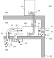
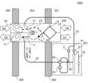
- FIG. 1 is a schematic configuration diagram of an outside air conditioner according to Embodiment 1.
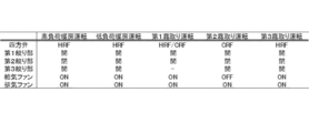
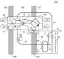
- FIG. FIG. 4 is an explanatory diagram showing the state of each mechanism during operation of the outside air conditioner according to Embodiment 1; 4 is another schematic configuration diagram of the outside air conditioner according to Embodiment 1.
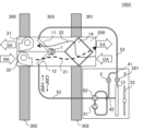
- FIG. FIG. 4 is a schematic configuration diagram of an outside air conditioner according to Embodiment 2;
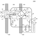
- FIG. 10 is a schematic configuration diagram of an outside air conditioner according to Embodiment 3;
- FIG. 11 is a schematic configuration diagram of an outside air conditioner according to Embodiment 4;
- FIG. 11 is a schematic configuration diagram of an outside air conditioner according to Embodiment 5;
- FIG. 11 is another schematic configuration diagram of the outside air conditioner according to Embodiment 5;
- FIG. 11 is another schematic configuration diagram of the outside air conditioner according to Embodiment 5;
- Embodiment 1 An outdoor air conditioner 1001 according to Embodiment 1 will be described with reference to FIGS. 1 to 3.
- FIG. 1 An outdoor air conditioner 1001 according to Embodiment 1 will be described with reference to FIGS. 1 to 3.
- FIG. 1 An outdoor air conditioner 1001 according to Embodiment 1 will be described with reference to FIGS. 1 to 3.
- OA indicated by an arrow indicates outside air
- SA indicates supply air
- EA indicates exhaust air
- a first path 21 indicates a path until outside air is supplied by an air supply fan 31
- a second path 22 indicates a path until return air is exhausted by an exhaust fan 32 .
- HRF indicated by an arrow indicates the direction of refrigerant flow during heating operation
- CRF indicated by an arrow indicates the direction of refrigerant flow during cooling operation.
- the flow of the refrigerant in the four-way valve 52 during the cooling operation is indicated by a dashed line
- the refrigerant flow during the heating operation is indicated by a solid line.
- the outside air processing unit 200 having the supply air fan 31, the first heat exchanger 11, the exhaust fan 32, the second heat exchanger 12, and the total heat exchanger 14 is installed, for example, in an installation space 303 sandwiched between walls 302. be.
- a heat source unit 201 having a compressor 51 for compressing refrigerant and a four-way valve 52 for distributing the compressed refrigerant is installed in an outdoor space 301, for example.
- the installation space 303 is adjacent to the indoor space 300 to be heated or cooled via the wall 302 , and is also adjacent to the outdoor space 301 via the wall 302 .
- the heat source unit 201 includes a heat source fan 33 that takes in outside air, and a third heat exchanger 13 that exchanges heat with the taken outside air.
- a refrigerant pipe 53 is provided so that the refrigerant flows through the four-way valve 52 . Then, in the refrigerant pipe 53 connecting the second heat exchanger 12 and the third heat exchanger 13, the first refrigerant pipe branch 41 and the second refrigerant pipe branch 41 and the second Refrigerant piping branches 42 are provided, and the second throttle section 2 for adjusting the flow of the refrigerant is provided between them.
- the refrigerant circuit includes a compressor 51 connected by a refrigerant pipe 53, a four-way valve 52, a first heat exchanger 11, a first throttle portion 1, a second heat exchanger 12, a third heat exchanger 13, The four-way valve 52 and the compressor 51 are formed in this order.
- the refrigerant pipe 53 includes a first refrigerant pipe branch 41 between the second heat exchanger 12 and the third heat exchanger 13 and a second refrigerant pipe branch 41 between the third heat exchanger 13 and the compressor 51 .
- a pipe branch 42 is provided between the first refrigerant pipe branch 41 and the second refrigerant pipe branch 42 and the second throttle portion 2 is provided.
- a refrigerant circuit without 13 is formed.
- the air supply fan 31 blows air from the outdoor space 301 to the indoor space 300 .
- the air supply fan 31 is provided on the first path 21, and supplies the air in the outdoor space 301 to the total heat exchanger 14, the air that has passed through the total heat exchanger 14, which is a heat exchange fluid, to the first heat exchanger 11, and supplies the air to the room. Air that has passed through the first heat exchanger 11 is supplied to the space 300 .
- the exhaust fan 32 blows air from the indoor space 300 to the outdoor space 301 .
- the exhaust fan 32 is provided in the second path 22 and supplies the air in the indoor space 300, which is a heat exchange fluid, to the second heat exchanger 12, and the air that has passed through the second heat exchanger 12 to the total heat exchanger 14. do.
- the air supply fan 31 and the exhaust fan 32 are composed of, for example, a centrifugal fan, an axial flow fan, a cross flow fan, or the like. The shape, form, etc. of the air supply fan 31 and the exhaust fan 32 may be different.
- the first heat exchanger 11 functions as a condenser during heating operation and as an evaporator during cooling operation.
- the second heat exchanger 12 functions as an evaporator or a condenser during heating operation, and mainly as a condenser during cooling operation.
- the first heat exchanger 11 and the second heat exchanger 12 are configured by, for example, a fin-and-tube heat exchanger having fins and heat transfer tubes, a microchannel heat exchanger having small-diameter heat transfer tubes, or the like.
- the shape, form, etc. of the first heat exchanger 11 and the second heat exchanger 12 may be different.
- the total heat exchanger 14 exchanges latent heat and sensible heat between the air in the outdoor space 301 and the air that has passed through the second heat exchanger 12 .
- the total heat exchanger 14 is composed of, for example, a rotary total heat exchanger, a static total heat exchanger, or the like.
- the first throttle section 1 expands and decompresses the refrigerant that has passed through the first heat exchanger 11 or the second heat exchanger 12 .
- the first throttle section 1 is composed of, for example, an electric expansion valve whose opening degree is variably controlled, and has one end connected to the first heat exchanger 11 and the other end connected to the second heat exchanger 12 .
- a mechanical expansion valve using a diaphragm as a pressure receiving portion, a capillary tube, or the like may be applied to the first throttle portion 1 .
- the third heat exchanger 13 functions as an evaporator during heating operation and as a condenser during cooling operation.
- the third heat exchanger 13 is composed of, for example, a fin-and-tube heat exchanger having fins and heat transfer tubes, a microchannel heat exchanger having small-diameter heat transfer tubes, or the like.
- the heat source unit fan 33 blows air from outside the heat source unit 201 into the heat source unit 201, and supplies the third heat exchanger 13 with the air outside the heat source unit 201, which is a heat exchange fluid.
- the heat source device fan 33 is configured by, for example, a centrifugal blower, an axial flow blower, a cross flow blower, or the like.
- the outdoor air conditioner 1001 also includes a control unit 54 (not shown).
- the control unit 54 is configured by, for example, an analog circuit, a digital circuit, a CPU (Central Processing Unit) and memory, or a combination of two or more of these.
- the control unit 54 controls the flow of the refrigerant by controlling the entire outside air conditioner 1001 based on instructions from an input device such as a remote controller.
- opening degree control of the first throttle portion 1 and the second throttle portion 2 rotation speed control of the air supply fan 31, exhaust fan 32 and heat source device fan 33, and frequency control of the compressor 51 are performed.
- the rotational speed control of the air supply fan 31, the exhaust fan 32, and the heat source device fan 33 includes ON/OFF switching.
- the controller 54 may be provided inside the outside air processing unit 200 or inside the heat source unit 201 . It may be provided in another housing.
- control unit 54 sets the four-way valve 52 to HRF, opens the first throttle section 1, closes the second throttle section 2, and opens the third throttle section 3. , and control is performed so that the air supply fan 31 and the exhaust fan 32 are operated.
- the compressor 51 sucks in the refrigerant and compresses it into a high-temperature and high-pressure state. Refrigerant compressed by the compressor 51 is discharged and sent to the four-way valve 52 .
- the compressor 51 is composed of, for example, a capacity-controllable inverter compressor, a rotary compressor, a scroll compressor, a screw compressor, a reciprocating compressor, or the like.
- the four-way valve 52 switches the refrigerant flow between heating operation and cooling operation.
- the four-way valve 52 connects the discharge port of the compressor 51 and the first heat exchanger 11 and connects the suction port of the compressor 51 with the third heat exchanger 13 and the second throttle section 2 during heating operation. switch the refrigerant flow to Further, the four-way valve 52 connects the discharge port of the compressor 51 to the third heat exchanger 13 and the second throttle portion 2 and connects the suction port of the compressor 51 to the first heat exchanger 11 during cooling operation. switch the refrigerant flow to connect the
- the second throttle section 2 is provided between the first refrigerant pipe branch 41 and the second refrigerant pipe branch 42 to adjust the flow of refrigerant.
- the refrigerant forms a refrigerant circuit that does not pass through the third heat exchanger 13 having a large pressure loss.
- the second throttle portion 2 is composed of, for example, an electric expansion valve whose opening degree can be variably controlled.
- a mechanical expansion valve using a diaphragm in the pressure receiving portion, a capillary tube, or the like may be used.
- R32 refrigerant, R410A, etc. may be used.
- High-temperature and high-pressure gaseous refrigerant is discharged from the compressor 51.
- High-temperature and high-pressure gas refrigerant (single-phase) discharged from the compressor 51 flows through the four-way valve 52 into the first heat exchanger 11 functioning as a condenser.
- the first heat exchanger 11 heat is exchanged between the high-temperature and high-pressure gas refrigerant that has flowed in and the air in the first path 21 that is supplied from the outdoor space 301 to the indoor space 300 by the air supply fan 31.
- the high-temperature and high-pressure gas refrigerant is condensed into a high-pressure liquid refrigerant (single-phase).
- the high-pressure liquid refrigerant sent out from the first heat exchanger 11 becomes a two-phase refrigerant of low-pressure gas refrigerant and liquid refrigerant by the first throttle portion 1 .
- the two-phase refrigerant flows into the second heat exchanger 12 functioning as an evaporator and the downstream third heat exchanger 13 .
- the second heat exchanger 12 heat is exchanged between the flowing two-phase refrigerant and the air in the second path 22 supplied from the indoor space 300 to the outdoor space 301 by the exhaust fan 32 .
- the third heat exchanger 13 heat is exchanged between the two-phase refrigerant flowing from the second heat exchanger 12 and the outside air blown by the heat source device fan 33 . From the second heat exchanger 12 to the third heat exchanger 13, the liquid refrigerant of the two-phase refrigerant evaporates to become a low-pressure gas refrigerant (single-phase).
- the low-pressure gas refrigerant sent out from the third heat exchanger 13 flows into the compressor 51 via the four-way valve 52, is compressed into high-temperature and high-pressure gas refrigerant, and is discharged from the compressor 51 again. This cycle is then repeated.
- the refrigerant flowing out of the third heat exchanger 13 during heating operation is a gas refrigerant (single-phase).
- the second throttle part 2 is closed to promote heat exchange in the third heat exchanger 13, so that the refrigerant mixes with the heat of the indoor space 300 and the outdoor space 301.
- High power operation can be realized by exchanging heat.
- the second throttle portion 2 is opened, and most of the refrigerant passes through a refrigerant circuit that does not pass through the third heat exchanger 13, which is a pressure loss body, so that the heat exchange of the third heat exchanger 13 is suppressed, and the refrigerant exchanges heat with the heat in the indoor space 300, so low input operation can be realized.
- the air during the heating operation is driven from the outdoor to the indoor through the first path 21 in FIG. 1 by driving the air supply fan 31 as described above.
- the air that has flowed into the outdoor air processing unit 200 from the outdoor space 301 is heated and humidified by exchanging sensible heat and latent heat with the air in the first path 21 in the total heat exchanger 14 .
- the air is further heated by the first heat exchanger 11 operating as a condenser and supplied to the indoor space 300 .
- an airflow is formed in the second path 22 from the return air to the exhaust.
- the air that has flowed from the indoor space 300 into the outdoor air processing unit 200 is cooled by the second heat exchanger 12 that operates as an evaporator, whereby heat is recovered in the refrigerant, and sensible heat and latent heat are exchanged by the downstream total heat exchanger 14. is performed, cooled and dehumidified, and discharged to the outdoor space 301 .
- the outside air is taken into the heat source unit 201 by driving the heat source unit fan 33, and discharged out of the heat source unit 201 again via the third heat exchanger 13.
- the moisture condensed on the third heat exchanger 13 from the outside air forms frost
- the heat exchange performance of the third heat exchanger 13 may be degraded due to the formation of frost that blocks the air passage.
- the temperature of the air in the total heat exchanger 14 that takes in the low-temperature outside air in the first path 21 becomes 0° C. or less
- the moisture dehumidified from the airflow in the second path 22 is removed in the total heat exchanger 14 Frost may form, block the air passages, and reduce the heat exchange performance of the total heat exchanger 14 .
- the refrigerant flow during the first defrosting operation is the same as that during the heating operation and is indicated by HRF in FIG.
- the refrigerant and air flows from the refrigerant discharged from the compressor 51 until the refrigerant flows into the second heat exchanger 12 are the same as during the heating operation.
- the refrigerant and air flows from the refrigerant discharged from the compressor 51 until the refrigerant flows into the second heat exchanger 12 are the same as during the heating operation.
- the second heat exchanger 12 heat is exchanged between the flowing two-phase refrigerant and the air in the second path 22 that is supplied from the indoor space 300 to the outdoor space 301 by the exhaust fan 32.
- the liquid refrigerant evaporates to become a low-temperature gas refrigerant (single-phase).
- the second heat exchanger 12 exchanges heat with return air having a higher temperature than the outside air, it is possible to supply refrigerant having a higher temperature than the outside air downstream.
- the low-pressure gas refrigerant (single-phase) sent out from the second heat exchanger 12 is branched at the first refrigerant pipe branch 41, and most of the refrigerant , part of the refrigerant passes through the third heat exchanger 13 and then joins at the second refrigerant pipe branch 42 .
- the reason why most of the refrigerant does not pass through the third heat exchanger 13 and passes through the refrigerant circuit without the third heat exchanger 13 is that the third heat exchanger 13 becomes a pressure loss body. Since the temperature of the refrigerant that has absorbed heat from the return air in the second heat exchanger 12 is 0° C. or higher, the low-pressure gas refrigerant (single-phase) melts the frost formed in the third heat exchanger 13 and partially It liquefies and becomes a two-phase refrigerant.
- the liquefaction of the low-pressure gas refrigerant can be reduced compared to when the second throttle portion 2 is closed. , the dryness of the refrigerant sucked into the compressor 51 is improved, and the operation can be performed without excessively flowing the liquid refrigerant to the compressor 51 .
- the outside air conditioning device 1001 includes a refrigerant pipe 53 that serves as a refrigerant flow path, a controller 54 that controls the flow of the refrigerant, and a compressor that is provided in the refrigerant pipe 53 and sucks the refrigerant and discharges the compressed refrigerant.
- One side is connected to the first heat exchanger 11 or the second heat exchanger 12 and the other side is connected to the compressor 51 by the first throttle portion 1 to be adjusted and the refrigerant pipe 53, and the refrigerant and the outside air flowing through the refrigerant pipe 53 are connected.
- the third heat exchanger 13 is branched by a first refrigerant pipe branch 41 located and a second refrigerant pipe branch 42 located midway in the refrigerant pipe 53 connecting the third heat exchanger 13 and the compressor 51.
- the flow path does not pass through the third heat exchanger 13 , and the flow path does not pass through the third heat exchanger 13 .
- the frost formed on the third heat exchanger 13 can be melted, and warm air is supplied to the indoor space 300.
- the temperature maintenance of 300 and the defrosting of the 3rd heat exchanger 13 can be made compatible.
- the refrigerant that flows into the second heat exchanger 12 that functions as an evaporator recovers heat from the return air that is hotter than the outside air, so it becomes a gaseous refrigerant (single phase) that is hotter than the outside air.
- a gaseous refrigerant single phase
- heat is radiated, enabling defrosting.
- the refrigerant that has passed through the second throttle portion 2 and the third heat exchanger 13 is turned into a high-temperature, high-pressure gas refrigerant in the compressor 51 and is discharged from the compressor 51 again.
- the high-temperature and high-pressure gas refrigerant passes through the first heat exchanger 11 functioning as a condenser, the temperature of the air that has passed through the total heat exchanger 14 in the first path 21 is increased. Since the air is supplied to the indoor space 300 as supply air, hot air can be supplied to the indoor space 300 in parallel with the defrosting of the third heat exchanger 13 .
- the airflow in the first path 21 passes through the first heat exchanger 11 via the total heat exchanger 14, thereby passing the air passing through the second heat exchanger 12 and the first heat exchanger 11.
- the temperature is raised by recovering heat from the high-temperature and high-pressure gas refrigerant, and the heating capacity in the first defrosting operation is improved.
- the airflow in the second path 22 passes through the total heat exchanger 14 via the second heat exchanger 12, so that when passing through the second heat exchanger 12, heat is released to the refrigerant to lower the temperature, Since the temperature difference between the airflows of the first path 21 and the second path 22 heat-exchanged in the total heat exchanger 14 becomes small, it is possible to improve temperature efficiency and suppress frost formation.
- the second refrigerant pipe branch 42 is provided between the third heat exchanger 13 and the four-way valve 52 . It may be provided between the suction port of the compressor 51 . Furthermore, by providing a refrigerant tank on the refrigerant pipe 53 from the four-way valve 52 to the compressor 51 , excessive inflow of liquid refrigerant into the compressor 51 can be suppressed.
- FIG. 1 shows an example in which the air supply fan 31 and the exhaust fan 32 are installed on the wall 302 separating the indoor space 300 and the installation space 303.
- the air supply fan 31 and the exhaust fan 32 may be arranged anywhere as long as the air flows of the first path 21 and the second path 22 are formed.
- the first path 21 and the second path 22 may be surrounded by another housing such as a duct 55 or the like.
- a blower unit 202 may be provided on the first path 21 and the second path 22, and a filter or the like may be provided on the first path 21 to add a foreign matter removing function.
- outside air processing unit 200 and the heat source unit 201 are installed in separate housings in the installation space 303 and the outdoor space 301 . They may be configured in the same housing and connected by the refrigerant pipe 53. It can be installed in another space as long as it is available.
- outside air processing unit 200 and the heat source unit 201 are connected one by one by the refrigerant pipe 53 .
- a plurality of outside air processing units 200 can be connected by providing a refrigerant distribution unit that divides the flow of the refrigerant on the refrigerant pipe 53 .
- An internal air circulation unit that circulates the refrigerant in the refrigerant pipe 53 may be provided.
- a heat source load unit or the like that uses water or the like as a working fluid may be provided.
- the refrigerant circuit and the air flow path of the outside air conditioner 1001 are arranged in the horizontal direction of the paper surface
- they may be arranged in the depth direction of the paper surface instead of defining the direction of gravity.
- Embodiment 2 An outdoor air conditioner 1002 according to Embodiment 2 will be described with reference to FIG.
- Embodiment 1 the configuration in which the first refrigerant pipe branch 41 and the third heat exchanger 13 are connected by the refrigerant pipe 53 has been described, but in Embodiment 2, the first refrigerant pipe branch 41 and the third heat exchanger The difference is that the refrigerant pipe 53 connecting to the vessel 13 is provided with the third throttle portion 3 .
- Other configurations are the same as those of the first embodiment.
- high-temperature and high-pressure gaseous refrigerant is discharged from the compressor 51.
- the high-temperature and high-pressure gas refrigerant (single-phase) discharged from the compressor 51 melts the frost formed on the third heat exchanger 13 and liquefies.
- the second throttle section 2 is closed during the second defrosting operation.
- the high-pressure liquid refrigerant sent out from the third heat exchanger 13 becomes a low-temperature, low-pressure two-phase refrigerant by opening the third throttle portion 3 .
- the two-phase refrigerant flows into the second heat exchanger 12 that functions as an evaporator, and heat is exchanged with the air in the second path 22 that is supplied from the indoor space 300 to the outdoor space 301 by the exhaust fan 32 .
- the liquid refrigerant in the two-phase state evaporates to become gas refrigerant (single-phase), and the refrigerant flows into the first heat exchanger 11 through the first throttle portion 1 .
- the low-temperature and low-pressure gas refrigerant does not exchange heat with the air in the first path 21, flows into the compressor 51 via the four-way valve 52, and is compressed into a high-temperature and high-pressure gas refrigerant. , and is discharged from the compressor 51 again, and this cycle is repeated.
- the outside air conditioner 1002 in the present embodiment does not stop the compressor 51, so that the hot air supply to the indoor space 300 is stopped for a period of time can be shortened. Therefore, it is possible to both maintain the temperature of the indoor space 300 and defrost the total heat exchanger 14 .
- the low-temperature, low-pressure two-phase refrigerant sent out from the third throttle portion 3 recovers heat from the return air in the second heat exchanger 12, and the low-temperature, low-pressure gas refrigerant ( single phase). Therefore, it is possible to prevent excessive inflow of the liquid refrigerant into the compressor 51 and shorten the heating stop time due to stopping the compressor 51 .
- the second heat exchanger 12 can recover heat from the return air and turn it into a low-temperature, low-pressure gas refrigerant. Therefore, the density of the liquid refrigerant in the low-temperature, low-pressure two-phase refrigerant that passes through the refrigerant pipe 53 from the third heat exchanger 13 to the second heat exchanger 12 is increased, and the surplus of the liquid refrigerant circulating in the refrigerant circuit is increased. can be reduced. Therefore, excessive inflow of the liquid refrigerant into the compressor 51 can be prevented, and heating stoppage due to stoppage of the compressor 51 can be prevented.
- the low-temperature low-pressure gas refrigerant sent out from the second heat exchanger 12 is It is possible to prevent liquefaction when passing through the heat exchanger 11 .
- the refrigerant flow during the third defrosting operation is the same as during the heating operation, and is indicated by HRF in FIG.
- High-temperature and high-pressure gaseous refrigerant is discharged from the compressor 51.
- High-temperature and high-pressure gas refrigerant (single-phase) discharged from the compressor 51 flows through the four-way valve 52 into the first heat exchanger 11 and the second heat exchanger 12 functioning as condensers.
- the second throttle section 2 is closed during the third defrosting operation.
- the high-pressure liquid refrigerant (single-phase) sent out from the second heat exchanger 12 becomes two-phase refrigerant of low-temperature low-pressure gas refrigerant and liquid refrigerant by opening the third throttle portion 3 .
- the two-phase refrigerant having a temperature lower than the air temperature flows into the third heat exchanger 13 functioning as an evaporator.
- heat is exchanged between the flowing two-phase refrigerant and the outside air blown by the heat source device fan 33 .
- the liquid refrigerant of the two-phase refrigerant evaporates to become a low-pressure gas refrigerant (single-phase).
- the low-pressure gas refrigerant sent out from the third heat exchanger 13 flows into the compressor 51 via the four-way valve 52, is compressed into high-temperature and high-pressure gas refrigerant, and is discharged from the compressor 51 again. This cycle is then repeated.
- the outdoor air conditioner 1002 in the present embodiment supplies warm air to the indoor space 300 while performing the third defrosting operation to melt the frost formed on the total heat exchanger 14. Defrosting of the heat exchanger 14 can be compatible.
- the third defrosting operation will be described in detail.
- the second heat exchanger 12 functioning as a condenser
- heat is released from the indoor space 300 into the return air. , to raise the temperature of the return air.
- the heated return air passes through the frosted total heat exchanger 14, it radiates heat, enabling defrosting.
- the temperature of the air that has passed through the total heat exchanger 14 in the first path 21 is increased. do. Since the air is supplied to the indoor space 300 as supply air, hot air can be supplied to the indoor space 300 in parallel with the defrosting of the total heat exchanger 14 .
- Embodiment 3 The external air conditioner 1003 according to Embodiment 3 will be described with reference to FIG.
- Embodiment 2 the configuration in which the third throttle portion 3 is provided in the refrigerant pipe 53 that connects the first refrigerant pipe branch 41 and the third heat exchanger 13 has been described.
- the second heat exchanger 12 is connected to the compressor 51, and the first heat exchanger 11 is connected to the third heat exchanger 13 via the refrigerant pipe 53, respectively. Accordingly, the positions of the first path 21 and the second path 22 of the air supply fan 31 and the exhaust fan 32 are switched.
- Other configurations are the same as those of the second embodiment.
- High-temperature and high-pressure gaseous refrigerant By driving the compressor 51, high-temperature and high-pressure gaseous refrigerant is discharged from the compressor 51.
- High-temperature and high-pressure gas refrigerant (single-phase) discharged from the compressor 51 flows through the four-way valve 52 into the second heat exchanger 12 and the first heat exchanger 11 functioning as condensers.
- the high-pressure liquid refrigerant (single-phase) sent out from the first heat exchanger 11 becomes two-phase refrigerant of low-pressure gas refrigerant and liquid refrigerant through the third throttle portion 3 .
- the two-phase refrigerant flows into the third heat exchanger 13 functioning as an evaporator.
- heat is exchanged between the flowing two-phase refrigerant and the outside air blown by the heat source device fan 33 .
- the liquid refrigerant of the two-phase refrigerant evaporates to become a low-pressure gas refrigerant (single-phase).
- the low-pressure gas refrigerant sent out from the third heat exchanger 13 flows into the compressor 51 via the four-way valve 52, is compressed into high-temperature and high-pressure gas refrigerant, and is discharged from the compressor 51 again. This cycle is then repeated.
- the second throttle part 2 is closed to promote heat exchange in the third heat exchanger 13, whereby the refrigerant exchanges heat with the heat in the indoor space 300 and the outdoor space 301, realizing high-output operation. do.
- the high-pressure liquid refrigerant sent out from the second heat exchanger 12 is converted to a refrigerant with a temperature lower than the air temperature by the first throttle portion 1, and the first heat exchanger 11 is operated as an evaporator.
- the refrigerant sent out from the first heat exchanger 11 be a low-pressure gas refrigerant (single-phase).
- the air supply fan 31 and the exhaust fan 32 are arranged corresponding to the positions of the first heat exchanger 11 and the second heat exchanger 12. Unlike forms 1 and 2, the first path 21 and the second path 22 are reversed, but the air supplied by the first heat exchanger 11 and the second heat exchanger 12 and the total heat exchanger 14 Since the heat-exchanged air is the same as in Embodiments 1 and 2, the description of the air flow in outside air conditioner 1003 is omitted.
- high-temperature and high-pressure gaseous refrigerant is discharged from the compressor 51 .
- the high-temperature and high-pressure gas refrigerant (single-phase) discharged from the compressor 51 is branched at the second refrigerant pipe branch 42, most of the refrigerant passes through the refrigerant circuit without the third heat exchanger 13, and some refrigerant After passing through the third heat exchanger 13 , the refrigerant joins at the first refrigerant pipe branch 41 .
- the temperature of the high-temperature and high-pressure gas refrigerant (single-phase) discharged from the compressor 51 is 0° C. or higher, the high-temperature and high-pressure gas refrigerant (single-phase) melts the frost formed in the third heat exchanger 13. do.
- the high-temperature, high-pressure refrigerant that joins at the first refrigerant pipe branch 41 flows into the first heat exchanger 11 that functions as a condenser.
- the first heat exchanger 11 heat is exchanged between the high-temperature, high-pressure refrigerant that has flowed in and the air in the first path 21 that is supplied from the outdoor space 301 to the indoor space 300 by the air supply fan 31.
- gas refrigerant is condensed into a high-pressure liquid refrigerant (single-phase).
- the high-pressure liquid refrigerant (single-phase) sent out from the first heat exchanger 11 becomes a two-phase refrigerant of low-pressure gas refrigerant and liquid refrigerant through the first throttle portion 1 .
- the two-phase refrigerant flows into the second heat exchanger 12 which functions as an evaporator.
- the second heat exchanger 12 heat is exchanged between the flowing two-phase refrigerant and the air in the second path 22 supplied from the indoor space 300 to the outdoor space 301 by the exhaust fan 32 .
- the liquid refrigerant of the two-phase refrigerant evaporates to become a low-pressure gas refrigerant (single-phase).
- the low-pressure gas refrigerant sent out from the second heat exchanger 12 flows into the compressor 51 via the four-way valve 52, is compressed into high-temperature and high-pressure gas refrigerant, and is discharged from the compressor 51 again. This cycle is then repeated.
- outdoor air conditioner 1003 in the present embodiment supplies warm air to indoor space 300 while performing the first defrosting operation to melt frost formed on third heat exchanger 13, the temperature of indoor space 300 is maintained and the temperature of indoor space 300 is maintained. Both defrosting of the third heat exchanger 13 can be achieved.
- the high-temperature and high-pressure gas refrigerant (single-phase) is supplied to the first heat exchanger 11 functioning as a condenser via the second throttle section 2, and the total heat exchanger of the first path 21
- the air passing through 14 is heated. Since the air is supplied to the indoor space 300 as supply air, hot air can be supplied to the indoor space 300 in parallel with the defrosting of the third heat exchanger 13 .
- Embodiment 4 The outdoor air conditioner 1004 according to Embodiment 4 will be described with reference to FIG.
- Embodiment 2 the configuration in which the second heat exchanger 12 and the four-way valve 52 are connected by the refrigerant pipe 53 via the first throttle portion 1 and the first heat exchanger 11 has been described.
- a third refrigerant pipe branch 43 is provided between the second heat exchanger 12 and the first throttle portion 1
- a fourth refrigerant pipe branch 44 is provided between the first heat exchanger 11 and the compressor 51
- a third The fourth throttle portion 4 is provided in the refrigerant circuit formed by connecting the refrigerant pipe branch 43 and the fourth refrigerant pipe branch 44 by the refrigerant pipe 53 without interposing the first throttle portion 1 and the first heat exchanger 11 .
- Other configurations are the same as those of the second embodiment.
- the flow of refrigerant and air until the refrigerant is discharged from the compressor 51 and undergoes heat exchange in the second heat exchanger 12 is the same as in the second defrosting operation of the second embodiment.
- the low-pressure gas refrigerant (single-phase) sent out from the second heat exchanger 12 is branched at the third refrigerant pipe branch 43, and most of the refrigerant is a refrigerant circuit that does not pass through the first throttle portion 1 and the first heat exchanger 11, and a part of the refrigerant passes through the first throttle portion 1 and the first heat exchanger 11, and then at the fourth refrigerant pipe branch 44 Refrigerants join. Most of the refrigerant passes through the refrigerant circuit without passing through the first throttle portion 1 and the first heat exchanger 11 without passing through the first throttle portion 1 and the first heat exchanger 11 because the first heat exchange This is because the vessel 11 becomes a pressure loss body.
- the low-pressure gas refrigerant (single-phase) that has passed through the refrigerant pipe 53 that does not pass through the first throttle portion 1 and the first heat exchanger 11, and the refrigerant that has passed through the first throttle portion 1 and the first heat exchanger 11 are the fourth
- the refrigerant joins at the refrigerant pipe branch 44 flows into the compressor 51 via the four-way valve 52 , is compressed into a high-temperature and high-pressure gas refrigerant, and is discharged from the compressor 51 again. This cycle is then repeated.
- the outside air conditioner 1004 in the present embodiment shortens the stop time of hot air supply to the indoor space 300 during the second defrosting operation for melting the frost that has formed on the third heat exchanger 13, thereby enabling early The heating operation can be restarted, and both the temperature maintenance of the indoor space 300 and the defrosting of the total heat exchanger 14 can be achieved.
- the operation of the second defrosting operation in this embodiment is the same as the second defrosting operation in the second embodiment.
- the second defrosting operation is performed by opening the fourth throttle portion 4 so that the low-temperature, low-pressure gas refrigerant (single-phase) sent out from the second heat exchanger 12 does not pass through the first heat exchanger 11, From the third refrigerant pipe branch 43 it passes through the fourth refrigerant pipe branch 44 .
- the first heat exchanger 11 is a pressure loss body.
- the low-temperature low-pressure gas refrigerant (single-phase) sent out from the second heat exchanger 12 is liquefied when passing through the first heat exchanger 11.
- excessive flow of liquefied refrigerant into the compressor 51 can be suppressed.
- Embodiment 5 The external air conditioner 1005 according to Embodiment 5 will be described with reference to FIGS. 7, 8, and 9.
- Other configurations are the same as those of the second embodiment.
- the opening/closing damper 56 is provided between the path downstream of the total heat exchanger 14 in the flow of supply air and the path upstream of the total heat exchanger 14 in the flow of exhaust air.
- the first path 21 is formed upstream and downstream of the total heat exchanger 14 in the flow of supply air
- the second path 22 is formed upstream and downstream of the total heat exchanger 14 in the flow of exhaust air.
- High-temperature and high-pressure gaseous refrigerant By driving the compressor 51, high-temperature and high-pressure gaseous refrigerant is discharged from the compressor 51.
- High-temperature and high-pressure gas refrigerant (single-phase) discharged from the compressor 51 flows through the four-way valve 52 into the first heat exchanger 11 and the second heat exchanger 12 functioning as condensers.
- the pressure of the air between the first heat exchanger 11 and the second heat exchanger 12 is higher than the atmospheric pressure. Therefore, part of the air that has passed through the second heat exchanger 12 flows into the total heat exchanger 14 .
- the outdoor air conditioner 1005 in the present embodiment supplies warm air to the indoor space 300 while performing the third defrosting operation to melt the frost formed on the total heat exchanger 14. Therefore, the temperature of the indoor space 300 is maintained and Defrosting of the heat exchanger 14 can be compatible.
- the third defrosting operation will be described in detail.
- the second heat exchanger 12 functioning as a condenser
- heat is released from the indoor space 300 into the return air. , to raise the temperature of the return air.
- a portion of the return air whose temperature has risen releases heat when passing through the frosted total heat exchanger 14, enabling defrosting.
- the second heat exchanger has already passed through the third path 23 in the internal air circulation operation. Heat is recovered from the high-temperature and high-pressure gas refrigerant (single-phase) at No. 12 to further raise the temperature of the air. Since the air is supplied to the indoor space 300 as supply air, hot air can be supplied to the indoor space 300 in parallel with the defrosting of the total heat exchanger 14 .
- the opening/closing damper 56 is positioned between the path downstream of the total heat exchanger 14 in the flow of supply air and the path downstream of the total heat exchanger 14 in the flow of exhaust air. may be set to By controlling the open/close damper 57, the return air from the indoor space 300 passes through the second heat exchanger 12 and the total heat exchanger 14, and then passes through the first heat exchanger 11 without being exhausted. , is supplied to the indoor space 300 as supply air. In this way, a third path is formed, and inside air circulation operation without heat exchange with the outside air is possible.
- a path 24 that is part of the first path 21 may be formed by penetrating the wall 302, and an opening/closing damper 58 may be provided on the wall surface. That is, the return air from the indoor space 300 passes through the second heat exchanger 12, passes through the total heat exchanger 14, passes through the path 24, passes through the first heat exchanger, and enters the indoor space 300 as supply air. It is also possible to enable inside air circulation operation in which heat is not exchanged with the outside air by supplying the inside air.
- the outdoor air conditioners 1005, 1006, and 1007 of the present embodiment it is possible to improve the amount of ventilation and maintain both the temperature of the indoor space 300 and the defrosting of the total heat exchanger 14.
Landscapes
- Engineering & Computer Science (AREA)
- Chemical & Material Sciences (AREA)
- Combustion & Propulsion (AREA)
- Mechanical Engineering (AREA)
- General Engineering & Computer Science (AREA)
- Air Conditioning Control Device (AREA)
- Central Air Conditioning (AREA)
- Air-Conditioning For Vehicles (AREA)
Abstract
外気調和装置(1000)は、給気及び還気が流れる給気ファン(31)及び排気ファン(32)、給気と還気とを熱交換する全熱交換器(14)、給気、還気及び外気と冷媒とを熱交換する第1熱交換器(11)、第2熱交換器(12)及び第3熱交換器(13)、冷媒配管(53)、制御部(54)、圧縮機(51)、冷媒の流れを調整する第1絞り部(1)及び第2絞り部(2)を備え、冷媒配管(53)には第1熱交換器(11)または第2熱交換器(12)と第3熱交換器(13)とを接続する冷媒配管(53)の途中に位置する第1冷媒配管分岐(41)と、第3熱交換器(13)と圧縮機(51)とを接続する冷媒配管(53)の途中に位置する第2冷媒配管分岐(42)とにより分岐される、第3熱交換器(13)を介さない流路が設けられ、第3熱交換器(13)を介さない流路に、第2絞り部(2)が設けられる。これにより、室内の温度を維持しつつ除霜ができる。
Description
本開示は、外気調和装置に関わる。
一般に外気調和装置は、ヒートポンプ回路中の熱交換器を用いて、外気、室内からの還気、又はその両方から熱回収する。このヒートポンプ回路において、圧縮機から吐出された高温高圧のガス冷媒は、熱交換器により凝縮され高圧の液冷媒となり、膨張弁によって減圧され低圧のガス冷媒と液冷媒との二相状態の冷媒となる。二相状態の冷媒は、熱交換器により蒸発され低圧のガス冷媒となり、圧縮機に吸入され高温高圧のガス冷媒となり、再び圧縮機から吐出される。そして、このサイクルが繰り返される。このときヒートポンプ回路の空気の流れは、送風機により取り込まれた外気が、熱交換器で昇温又は降温されて室内に供給され、送風機により室内から取り込まれた還気が、熱交換器で放熱又は熱回収され再び室外へ排気され、このサイクルが繰り返される。
例えば、特許文献1に開示された潜熱処理モジュールのヒートポンプ回路では、冷媒回路、圧縮機、四方弁、水熱交換器等の熱交換器、膨張弁、送風機等を操作することにより、室内の温度及び湿度調整が行われる。
しかしながら、熱交換器が低温の外気に曝される場合、表面に霜が付着することがあり、霜がヒートポンプ回路を閉塞しないよう、従来では室内への給気を停止し、圧縮機から高温高圧のガス冷媒を熱交換器へ供給する等して霜を取り除いていた。このように給気を長時間停止すると、室内の温度が低下するという課題があった。
本開示は、上述した課題を解決するためになされたものであり、室内の温度を維持しつつ除霜ができる外気調和装置を提供することを目的とする。
本開示に係る外気調和装置は、冷媒の流路となる冷媒配管と、冷媒の流れを制御する制御部と、冷媒配管に設けられ、冷媒を吸入し、圧縮した冷媒を吐出する圧縮機と、室内に供給される給気が流れる第1経路に配置された給気ファンと、室内から排出される還気が流れる第2経路に配置された排気ファンと、給気と還気とを熱交換する全熱交換器と、第1経路の給気の流れにおける全熱交換器の下流に位置する第1熱交換器と、第2経路の還気の流れにおける全熱交換器の上流に位置する第2熱交換器と、第1熱交換器と第2熱交換器との間に設けられ、制御部により冷媒の流れを調整する第1絞り部と、冷媒配管により、一方が第1熱交換器または第2熱交換器に接続され、他方が圧縮機に接続され、冷媒配管を流れる冷媒と外気とを熱交換する第3熱交換器とを備え、冷媒配管は、第1熱交換器または第2熱交換器と第3熱交換器とを接続する冷媒配管の途中に位置する第1冷媒配管分岐と、第3熱交換器と圧縮機とを接続する冷媒配管の途中に位置する第2冷媒配管分岐とにより分岐される、第3熱交換器を介さない流路を有し、第3熱交換器を介さない流路に、制御部により冷媒の流れを調整する第2絞り部を有すること、を特徴とする。
本開示によれば、室内の温度を維持しつつ除霜ができる。
実施の形態1.
図1~図3を用いて実施の形態1における外気調和装置1001について説明する。
図1~図3を用いて実施の形態1における外気調和装置1001について説明する。
図1において、矢印で示すOAは外気を、SAは給気を示し、外気は、給気ファン31により室外空間301から全熱交換器14及び第1熱交換器11を経由して室内空間300へと供給される。矢印で示すRAは還気を、EAは排気を示し、還気は排気ファン32により室内空間300から第2熱交換器12及び全熱交換器14を経由して室外空間301へ排気される。
第1経路21は、給気ファン31により外気が給気されるまでの経路、第2経路22は、排気ファン32により還気が排気されるまでの経路を示す。
第1経路21は、給気ファン31により外気が給気されるまでの経路、第2経路22は、排気ファン32により還気が排気されるまでの経路を示す。
図1において、矢印で示すHRFは暖房運転時の冷媒の流れ方向、矢印で示すCRFは冷房運転時の冷媒流れ方向を示す。また、四方弁52における冷房運転時の冷媒の流れを破線で、暖房運転の冷媒流れを実線で示している。
給気ファン31、第1熱交換器11、排気ファン32、第2熱交換器12、全熱交換器14を有する外気処理ユニット200は、例えば、壁302に挟まれた設置空間303に設置される。冷媒を圧縮する圧縮機51、圧縮された冷媒を分配する四方弁52を有する熱源機ユニット201は、例えば室外空間301に設置される。設置空間303は、暖房又は冷房する室内空間300と壁302を介して隣接しており、室外空間301とも壁302を介して隣接している。
さらに、熱源機ユニット201は、外気を取り込む熱源機ファン33、取り込んだ外気と熱交換する第3熱交換器13を備え、暖房運転時には、第2熱交換器12から第3熱交換器13を経由して、四方弁52に冷媒が流れるように、冷媒配管53が設けられている。そして、第2熱交換器12と第3熱交換器13を繋ぐ冷媒配管53には、第3熱交換器13を経由せず四方弁52へ冷媒を流す、第1冷媒配管分岐41及び第2冷媒配管分岐42が設けられ、これらの間には、冷媒の流れを調整する第2絞り部2が設けられている。
暖房運転時、冷媒回路は、冷媒配管53により接続された圧縮機51、四方弁52、第1熱交換器11、第1絞り部1、第2熱交換器12、第3熱交換器13、四方弁52、圧縮機51の順で形成される。さらに、冷媒配管53には、第2熱交換器12と第3熱交換器13との間に第1冷媒配管分岐41が、第3熱交換器13と圧縮機51との間に第2冷媒配管分岐42が、第1冷媒配管分岐41と第2冷媒配管分岐42との間に第2絞り部2が設けられ、第1冷媒配管分岐41と第2冷媒配管分岐42により第3熱交換器13を介さない冷媒回路が形成される。
給気ファン31は、室外空間301から室内空間300へ空気を送風する。給気ファン31は第1経路21に設けられ、全熱交換器14に室外空間301の空気を、第1熱交換器11に熱交換流体である全熱交換器14を通過した空気を、室内空間300に第1熱交換器11を通過した空気を供給する。
排気ファン32は、室内空間300から室外空間301へ空気を送風する。排気ファン32は、第2経路22に設けられ、第2熱交換器12に熱交換流体である室内空間300の空気を、全熱交換器14に第2熱交換器12を通過した空気を供給する。給気ファン31、排気ファン32は、例えば、遠心送風機、軸流送風機、横流送風機等で構成される。給気ファン31、排気ファン32の形状、形態等は異なっていてもよい。
排気ファン32は、室内空間300から室外空間301へ空気を送風する。排気ファン32は、第2経路22に設けられ、第2熱交換器12に熱交換流体である室内空間300の空気を、全熱交換器14に第2熱交換器12を通過した空気を供給する。給気ファン31、排気ファン32は、例えば、遠心送風機、軸流送風機、横流送風機等で構成される。給気ファン31、排気ファン32の形状、形態等は異なっていてもよい。
第1熱交換器11は、暖房運転時に凝縮器、冷房運転時には蒸発器として機能する。第2熱交換器12は、暖房運転時に蒸発器又は凝縮器として、冷房運転時に主に凝縮器として機能する。第1熱交換器11、第2熱交換器12は、例えば、フィンと伝熱管を備えたフィンアンドチューブ型熱交換器、伝熱管が小径であるマイクロチャネル熱交換器等で構成される。第1熱交換器11、第2熱交換器12の形状、形態等は異なっていてもよい。
全熱交換器14は、室外空間301の空気と第2熱交換器12を通過した空気との間で潜熱及び顕熱の熱交換を行う。全熱交換器14は、例えば回転型全熱交換器、静止型全熱交換器等で構成される。
第1絞り部1は、第1熱交換器11又は第2熱交換器12を経由した冷媒を膨張させて減圧する。第1絞り部1は、例えば開度が可変に制御される電動膨張弁で構成され、一端が第1熱交換器11に接続され、他端が第2熱交換器12に接続されている。第1絞り部1は、受圧部にダイアフラムを用いた機械式膨張弁、キャピラリーチューブ等を適用してもよい。
第3熱交換器13は、暖房運転時に蒸発器、冷房運転時に凝縮器として機能する。第3熱交換器13は、例えばフィンと伝熱管を備えたフィンアンドチューブ型熱交換器、伝熱管が小径であるマイクロチャネル熱交換器等で構成される。
熱源機ファン33は、熱源機ユニット201外から熱源機ユニット201内へ空気を送風し、第3熱交換器13に、熱交換流体である熱源機ユニット201外の空気を供給する。熱源機ファン33は、例えば、遠心送風機、軸流送風機、横流送風機等で構成される。
また、外気調和装置1001は、図示しない制御部54を備える。制御部54は、例えばアナログ回路、デジタル回路、CPU(Central Processing Unit)及びメモリ、又はこれらのうちの2つ以上の組み合わせにより構成される。
制御部54は、リモコン等の入力装置からの指示に基づいて、外気調和装置1001の全体の制御することにより冷媒の流れを制御する。本実施の形態では、第1絞り部1及び第2絞り部2の開度制御、給気ファン31、排気ファン32及び熱源機ファン33の回転数制御、並びに圧縮機51の周波数制御を行う。給気ファン31、排気ファン32及び熱源機ファン33の回転数制御はON/OFFの切替えも含む。制御部54は、外気処理ユニット200内に設けてもよく、熱源機ユニット201内に設けてもよい。別の筐体内に設けてもよい。
制御部54は、リモコン等の入力装置からの指示に基づいて、外気調和装置1001の全体の制御することにより冷媒の流れを制御する。本実施の形態では、第1絞り部1及び第2絞り部2の開度制御、給気ファン31、排気ファン32及び熱源機ファン33の回転数制御、並びに圧縮機51の周波数制御を行う。給気ファン31、排気ファン32及び熱源機ファン33の回転数制御はON/OFFの切替えも含む。制御部54は、外気処理ユニット200内に設けてもよく、熱源機ユニット201内に設けてもよい。別の筐体内に設けてもよい。
図2に示すように、制御部54は、例えば高負荷暖房運転の場合、四方弁52をHRFに、第1絞り部1を開、第2絞り部2を閉、第3絞り部3を開とし、給気ファン31及び排気ファン32を作動するように制御を行う。
圧縮機51は、冷媒を吸入し、圧縮して高温高圧の状態にする。圧縮機51で圧縮された冷媒は、吐出されて四方弁52へ送られる。圧縮機51は、例えば容量制御可能なインバータ圧縮機、ロータリー圧縮機、スクロール圧縮機、スクリュー圧縮機、往復圧縮機等で構成される。
四方弁52は、暖房運転と冷房運転とにおいて冷媒の流れを切り替える。四方弁52は、暖房運転時、圧縮機51の吐出口と第1熱交換器11とを接続するとともに、圧縮機51の吸入口と第3熱交換器13及び第2絞り部2とを接続するように冷媒の流れを切り替える。また、四方弁52は、冷房運転時、圧縮機51の吐出口と第3熱交換器13及び第2絞り部2とを接続するとともに、圧縮機51の吸入口と第1熱交換器11とを接続するように冷媒の流れを切り替える。
第2絞り部2は、第1冷媒配管分岐41と第2冷媒配管分岐42との間に設けられ、冷媒の流れを調整する。第2絞り部2を開とすると、冷媒は圧損の大きな第3熱交換器13を介さない冷媒回路を形成する。第2絞り部2は、例えば開度が可変に制御できる電動膨張弁で構成される。受圧部にダイアフラムを用いた機械式膨張弁、キャピラリーチューブ等を用いてもよい。
冷媒回路に用いる冷媒としては、例えばR32冷媒、R410A等を用いればよい。特に後述の第2霜取り運転においては、HFO1234yf、HFO1234ze(E)等のオレフィン系冷媒、又はプロパン、DME(ジメチルエーテル)を含むR32冷媒に対してガス密度の小さい冷媒を用いれば霜取り能力が大きくなり好ましい。
<外気調和装置1001の動作>
室外空間301の空気を室内空間300に昇温して給気する暖房運転する場合の外気調和装置1001の動作について説明する。暖房運転時の冷媒の流れは、図1中のHRFである。ここでは、熱交換流体が空気であり、被熱交換流体が冷媒である。
室外空間301の空気を室内空間300に昇温して給気する暖房運転する場合の外気調和装置1001の動作について説明する。暖房運転時の冷媒の流れは、図1中のHRFである。ここでは、熱交換流体が空気であり、被熱交換流体が冷媒である。
圧縮機51を駆動させることによって、圧縮機51から高温高圧のガス状態の冷媒が吐出する。圧縮機51から吐出した高温高圧のガス冷媒(単相)は、四方弁52を介して凝縮器として機能する第1熱交換器11に流れ込む。第1熱交換器11では、流れ込んだ高温高圧のガス冷媒と、給気ファン31によって室外空間301から室内空間300へ給気される第1経路21の空気との間で熱交換が行われて、高温高圧のガス冷媒が凝縮して高圧の液冷媒(単相)になる。
第1熱交換器11から送り出された高圧の液冷媒は、第1絞り部1によって低圧のガス冷媒と液冷媒との二相状態の冷媒になる。二相状態の冷媒は、蒸発器として機能する第2熱交換器12および下流の第3熱交換器13に流れ込む。第2熱交換器12では、流れ込んだ二相状態の冷媒と、排気ファン32によって室内空間300から室外空間301へ供給される第2経路22の空気との間で熱交換が行われる。第3熱交換器13では、第2熱交換器12から流れ込んだ二相状態の冷媒と、熱源機ファン33によって送風された外気との間で熱交換が行われる。第2熱交換器12から第3熱交換器13にかけて二相状態の冷媒のうち液冷媒が蒸発して低圧のガス冷媒(単相)になる。
第3熱交換器13から送り出された低圧のガス冷媒は、四方弁52を介して圧縮機51に流れ込み、圧縮されて高温高圧のガス冷媒となって、再び圧縮機51から吐出する。以下、このサイクルが繰り返される。
暖房運転の際、圧縮機51に冷媒が液状態で流入すると液圧縮を起こし、圧縮機51の故障の原因となってしまう。そのため、暖房運転時の第3熱交換器13から流出する冷媒はガス冷媒(単相)となっていることが望ましい。
例えば、図2に示すように、高負荷暖房運転時、第2絞り部2を閉じ、第3熱交換器13の熱交換を促進することで、冷媒が室内空間300及び室外空間301の熱と熱交換を行い高出力運転を実現できる。低負荷暖房運転時には、第2絞り部2を開け、冷媒の大部分が圧力損失体である第3熱交換器13を介さない冷媒回路を通過することで、第3熱交換器13の熱交換が抑えられ、冷媒が室内空間300の熱と熱交換を行うので低入力運転を実現できる。
暖房運転の際の空気は、先に述べたとおり給気ファン31を駆動させることで、図1中の第1経路21において室外から室内に流れる。室外空間301から外気処理ユニット200に流入した空気は全熱交換器14において第1経路21の空気と顕熱及び潜熱交換が行われ加熱及び加湿される。そして凝縮器として動作する第1熱交換器11によりさらに加熱され、室内空間300へ給気される。
また排気ファン32を駆動させることで、第2経路22において還気から排気までの気流が形成される。室内空間300から外気処理ユニット200に流入した空気は蒸発器として動作する第2熱交換器12によって冷却されることにより冷媒に熱が回収され、下流の全熱交換器14によって顕熱及び潜熱交換が行われ冷却及び除湿されて室外空間301に排出される。
熱源機ユニット201においては、熱源機ファン33を駆動させることで外気を熱源機ユニット201内へ取り込み、第3熱交換器13を介して再び熱源機ユニット201外へ排出する。
冷媒配管53を通過する冷媒が低温の外気により冷却され、第3熱交換器13の冷媒温度が0℃以下となる場合、外気から第3熱交換器13に結露した水分が霜を形成し、霜の形成により風路を閉塞して第3熱交換器13の熱交換性能が低下することがある。また第1経路21において低温の外気を取り込んだ全熱交換器14中の空気の温度が0℃以下となった場合、第2経路22における気流から除湿された水分が、全熱交換器14で霜を形成し、風路を閉塞して全熱交換器14の熱交換性能を低下させることがある。
第3熱交換器13に着霜した霜を融かす第1霜取り運転による外気調和装置1001の動作、冷媒及び空気流れについて説明する。第1霜取り運転時の冷媒の流れは、暖房運転時と同様であり図1中のHRFである。圧縮機51から冷媒が吐出し、冷媒が第2熱交換器12に流れ込むまでの冷媒及び空気流れは、暖房運転時と同様である。
圧縮機51から冷媒が吐出し、冷媒が第2熱交換器12に流れ込むまでの冷媒及び空気流れは、暖房運転時と同様である。
圧縮機51から冷媒が吐出し、冷媒が第2熱交換器12に流れ込むまでの冷媒及び空気流れは、暖房運転時と同様である。
第2熱交換器12では、流れ込んだ二相状態の冷媒と、排気ファン32によって室内空間300から室外空間301へ供給される第2経路22の空気との間で熱交換が行われ、二相状態の冷媒のうち液冷媒が蒸発して低温のガス冷媒(単相)になる。このとき、第2熱交換器12で外気より高温な還気と熱交換しているため、外気よりも高温な冷媒を下流に供給することが可能である。
第1霜取り運転では、第2絞り部2を開けることにより、第2熱交換器12から送り出された低圧のガス冷媒(単相)は、第1冷媒配管分岐41で分流し、大部分の冷媒は第3熱交換器13を介さない冷媒回路を、一部の冷媒は第3熱交換器13を通過した後、第2冷媒配管分岐42にて冷媒が合流する。大部分の冷媒が第3熱交換器13を通過せずに、第3熱交換器13を介さない冷媒回路を通過するのは、第3熱交換器13が圧力損失体となるからである。
第2熱交換器12にて還気から吸熱した冷媒温度は0℃以上であるので、低圧のガス冷媒(単相)が第3熱交換器13に形成される霜を融解し、一部が液化し、二相状態の冷媒となる。
第2熱交換器12にて還気から吸熱した冷媒温度は0℃以上であるので、低圧のガス冷媒(単相)が第3熱交換器13に形成される霜を融解し、一部が液化し、二相状態の冷媒となる。
第3熱交換器13を介さない冷媒回路を通過した低圧のガス冷媒(単相)及び第3熱交換器13を通過した二相状態の冷媒は、第2冷媒配管分岐42で合流し、四方弁52を介して圧縮機51に流れ込み、圧縮されて高温高圧のガス冷媒となって、再び圧縮機51から吐出する。以下、このサイクルが繰り返される。
したがって、第2絞り部2を開いて、第3熱交換器13を介さない冷媒回路を設けることにより、第2絞り部2を閉じた場合に比べて、低圧のガス冷媒の液化を低減できるので、圧縮機51に吸入される冷媒の乾き度が向上し、液冷媒を過剰に圧縮機51に流すことなく運転できる。
このように外気調和装置1001は、冷媒の流路となる冷媒配管53と、冷媒の流れを制御する制御部54と、冷媒配管53に設けられ、冷媒を吸入し、圧縮した冷媒を吐出する圧縮機51と、室内に供給される給気が流れる第1経路21に配置された給気ファン31と、室内から排出される還気が流れる第2経路22に配置された排気ファン32と、給気と還気とを熱交換する全熱交換器14と、第1経路21の給気の流れにおける全熱交換器14の下流に位置する第1熱交換器11と、第2経路22の還気の流れにおける全熱交換器14の上流に位置する第2熱交換器12と、第1熱交換器11と第2熱交換器12との間に設けられ、制御部54により冷媒の流れを調整する第1絞り部1と、冷媒配管53により、一方が第1熱交換器11または第2熱交換器12に接続され、他方が圧縮機51に接続され、冷媒配管53を流れる冷媒と外気とを熱交換する第3熱交換器13とを備え、冷媒配管53は、第1熱交換器11または第2熱交換器12と第3熱交換器13とを接続する冷媒配管53の途中に位置する第1冷媒配管分岐41と、第3熱交換器13と圧縮機51とを接続する冷媒配管53の途中に位置する第2冷媒配管分岐42とにより分岐される、第3熱交換器13を介さない流路を有し、第3熱交換器13を介さない流路に、制御部54により冷媒の流れを調整する第2絞り部2を有する。
そして、第1霜取り運転において、第2絞り部2を開けることにより、第3熱交換器13に着霜した霜を融かすことができるとともに、温風を室内空間300に供給するため、室内空間300の温度維持と第3熱交換器13の除霜を両立することができる。
そして、第1霜取り運転において、第2絞り部2を開けることにより、第3熱交換器13に着霜した霜を融かすことができるとともに、温風を室内空間300に供給するため、室内空間300の温度維持と第3熱交換器13の除霜を両立することができる。
第1霜取り運転について詳述すると、蒸発器として機能する第2熱交換器12に流入する冷媒は、外気より高温な還気から熱回収するため、外気より高温なガス冷媒(単相)となる。第2熱交換器12から送り出されたガス冷媒(単相)の一部が、霜が形成された第3熱交換器13を通過する際に、放熱するため除霜が可能となる。
第2絞り部2及び第3熱交換器13を通過した冷媒は、圧縮機51で高温高圧のガス冷媒となって再び圧縮機51から吐出される。高温高圧のガス冷媒が凝縮器として機能する第1熱交換器11を通過する際に、第1経路21の全熱交換器14を通過した空気を昇温する。当該空気が室内空間300に給気として供給されるので、第3熱交換器13の除霜と並行して室内空間300への温風供給が可能となる。
そして第1経路21の気流が、全熱交換器14を経由して第1熱交換器11を通過することにより、第2熱交換器12を通過した空気及び第1熱交換器11を通過する高温高圧のガス冷媒から熱回収することで昇温し、第1霜取り運転における暖房能力が向上する。
また、第2経路22の気流が、第2熱交換器12を経由して全熱交換器14を通過することにより、第2熱交換器12を通過時に、冷媒に放熱することで降温し、全熱交換器14で熱交換される第1経路21及び第2経路22の気流の温度差が小さくなるため、温度効率の向上及び着霜の抑制が可能となる。
なお、本実施の形態において、第2冷媒配管分岐42を第3熱交換器13と四方弁52との間に設ける例を示したが、第2冷媒配管分岐42は第3熱交換器13と圧縮機51の吸入口との間に設ければよい。さらに、四方弁52から圧縮機51に至る冷媒配管53上に冷媒タンクを設けることで、圧縮機51への液冷媒の過剰流入を抑制することができる。
また図1において、室内空間300と設置空間303を隔てる壁302に給気ファン31及び排気ファン32を設置する例を示したが、例えば図3に示すように、給気ファン31及び排気ファン32を室内空間300に設置してもよい。第1経路21及び第2経路22の空気流れが形成されれば、給気ファン31、排気ファン32はどこに配置してもよい。
また、図3に示すように、第1経路21及び第2経路22をダクト55等の別筐体で包囲してもよい。第1経路21及び第2経路22上に送風ユニット202、第1経路21上にフィルタ等を設け異物除去機能を付加してもよい。
また、図3に示すように、第1経路21及び第2経路22をダクト55等の別筐体で包囲してもよい。第1経路21及び第2経路22上に送風ユニット202、第1経路21上にフィルタ等を設け異物除去機能を付加してもよい。
また、外気処理ユニット200及び熱源機ユニット201は別筐体で設置空間303及び室外空間301に設置される例を示したが、同一筐体で構成してもよく、冷媒配管53で接続されている限りは別空間に設置してもよい。
また、外気処理ユニット200と熱源機ユニット201が一台ずつ冷媒配管53により接続されている例を示したが、冷媒配管53上に冷媒を分流する冷媒分流ユニットを設けて複数の外気処理ユニット200、熱源機ユニット201を構成してもよい。冷媒配管53に冷媒を循環させる内気循環ユニットを設けてもよい。水等を作動流体とする熱源負荷ユニット等を設けてもよい。
また、外気調和装置1001の冷媒回路及び空気流路を紙面水平方向に配置した例を示したが、重力方向を規定するものではなく、紙面奥行き方向に配置してもよい。
実施の形態2.
図4を用いて実施の形態2における外気調和装置1002について説明する。
実施の形態1において、第1冷媒配管分岐41と第3熱交換器13とを冷媒配管53で接続する構成について説明したが、実施の形態2では、第1冷媒配管分岐41と第3熱交換器13とを接続する冷媒配管53に第3絞り部3が設けられている点が異なる。それ以外の構成は実施の形態1と同様である。
図4を用いて実施の形態2における外気調和装置1002について説明する。
実施の形態1において、第1冷媒配管分岐41と第3熱交換器13とを冷媒配管53で接続する構成について説明したが、実施の形態2では、第1冷媒配管分岐41と第3熱交換器13とを接続する冷媒配管53に第3絞り部3が設けられている点が異なる。それ以外の構成は実施の形態1と同様である。
<外気調和装置1002の動作>
外気調和装置1002における第3熱交換器13に着霜した霜を融かす第2霜取り運転の冷媒及び空気流れについて説明する。第2霜取り運転時の冷媒の流れは、冷房運転時と同様であり図4にCRFで示している。
外気調和装置1002における第3熱交換器13に着霜した霜を融かす第2霜取り運転の冷媒及び空気流れについて説明する。第2霜取り運転時の冷媒の流れは、冷房運転時と同様であり図4にCRFで示している。
圧縮機51を駆動させることによって、圧縮機51から高温高圧のガス状態の冷媒が吐出する。圧縮機51から吐出した高温高圧のガス冷媒(単相)は、第3熱交換器13に形成される霜を融解し、液化する。
図2に示すように、第2霜取り運転時、第2絞り部2は閉じている。第3熱交換器13から送り出された高圧の液冷媒は、第3絞り部3を開くことによって低温低圧の二相状態の冷媒となる。二相状態の冷媒は、蒸発器として機能する第2熱交換器12に流れ込み、排気ファン32によって室内空間300から室外空間301へ供給される第2経路22の空気との間で熱交換が行われる。
続いて、二相状態の冷媒の液冷媒が蒸発しガス冷媒(単相)となった冷媒が第1絞り部1を介して第1熱交換器11へ流入する。低温低圧のガス冷媒は、給気ファン31をOFFにすることによって第1経路21の空気と熱交換を行わず、四方弁52を介して圧縮機51に流れ込み、圧縮されて高温高圧のガス冷媒となって、再び圧縮機51から吐出し、このサイクルが繰り返される。
本実施の形態における外気調和装置1002は、第3熱交換器13に着霜した霜を融かす第2霜取り運転時、圧縮機51を停止させないため室内空間300への温風供給の停止時間を短縮することができる。したがって、室内空間300の温度維持と全熱交換器14の除霜を両立することができる。
第2霜取り運転について詳述すると、圧縮機51から吐出した高温高圧のガス冷媒(単相)が、霜が形成された第3熱交換器13を通過する際に、放熱するため除霜が可能となる。
霜取り動作において、排気ファン32を停止し、第2熱交換器12にて還気から熱回収しない場合、低温低圧の二相状態の冷媒がそのまま第1絞り部1、第1熱交換器11及び四方弁52を経由して圧縮機51に吸入される。その結果、圧縮機51へ液冷媒が過剰に流入し、圧縮機51停止による暖房運転停止を引き起こすおそれがある。これに対し、第2霜取り運転では、第3絞り部3から送り出された低温低圧の二相状態の冷媒が、第2熱交換器12にて還気から熱回収し、低温低圧のガス冷媒(単相)となる。そのため、圧縮機51への液冷媒の過剰流入を防止し、圧縮機51停止による暖房停止時間の短縮が可能である。
また、第2熱交換器12を蒸発器として機能させることで、第2熱交換器12にて冷媒は還気から熱回収し、低温低圧のガス冷媒となることができる。そのため第3熱交換器13から第2熱交換器12までの冷媒配管53を通過する低温低圧の二相状態の冷媒のうち液冷媒の密度を大きくし、冷媒回路を循環する液冷媒の余剰分を削減することができる。したがって、圧縮機51への液冷媒の過剰流入を防止し、圧縮機51停止による暖房停止を防止できる。
また、第1絞り部1の開度調整を行い、第1熱交換器11の配管温度を外気以下とすることで、第2熱交換器12から送り出された低温低圧のガス冷媒が、第1熱交換器11通過時に液化するのを防止できる。
次に、外気調和装置1002における、全熱交換器14に着霜した霜を融かす第3霜取り運転の冷媒及び空気流れについて説明する。第3霜取り運転時の冷媒の流れは、暖房運転時と同様であり図4にHRFで示している。
圧縮機51を駆動させることによって、圧縮機51から高温高圧のガス状態の冷媒が吐出する。圧縮機51から吐出した高温高圧のガス冷媒(単相)は、四方弁52を介して凝縮器として機能する第1熱交換器11及び第2熱交換器12に流れ込む。第1熱交換器11及び第2熱交換器12では、流れ込んだ空気温度よりも高温な高温高圧のガス冷媒と、給気ファン31によって室外空間301から室内空間300へ給気される第1経路21の空気、及び排気ファン32によって室内空間300から室外空間301へ供給される第2経路22の空気との間でそれぞれ熱交換が行われて、高温高圧のガス冷媒が凝縮して高圧の液冷媒(単相)になる。
図2に示すように、第3霜取り運転時、第2絞り部2は閉じている。第2熱交換器12から送り出された高圧の液冷媒(単相)は、第3絞り部3を開にすることによって低温低圧のガス冷媒と液冷媒との二相状態の冷媒になる。空気温度よりも低温な二相状態の冷媒は、蒸発器として機能する第3熱交換器13に流れ込む。第3熱交換器13では、流れ込んだ二相状態の冷媒と、熱源機ファン33によって送風される外気との間で熱交換が行われる。第3熱交換器13では二相状態の冷媒のうち液冷媒が蒸発して低圧のガス冷媒(単相)になる。
第3熱交換器13から送り出された低圧のガス冷媒は、四方弁52を介して圧縮機51に流れ込み、圧縮されて高温高圧のガス冷媒となって、再び圧縮機51から吐出する。以下、このサイクルが繰り返される。
本実施の形態における外気調和装置1002は、全熱交換器14に着霜した霜を融かす第3霜取り運転をしながら温風を室内空間300に供給するため、室内空間300の温度維持と全熱交換器14の除霜を両立することができる。
第3霜取り運転について詳述すると、圧縮機51から吐出された高温高圧のガス冷媒が、凝縮器として機能する第2熱交換器12を通過する際に、室内空間300からの還気に放熱し、還気を昇温する。昇温した還気が、霜が形成された全熱交換器14を通過する際に、放熱するため除霜が可能となる。
さらに、圧縮機51から吐出された高温高圧のガス冷媒が、凝縮器として機能する第1熱交換器11を通過する際に、第1経路21の全熱交換器14を通過した空気を昇温する。当該空気が室内空間300に給気として供給されるので、全熱交換器14の除霜と平行して室内空間300への温風供給が可能となる。
実施の形態3.
図5を用いて実施の形態3における外気調和装置1003について説明する。
実施の形態2において、第1冷媒配管分岐41と第3熱交換器13とを接続する冷媒配管53に第3絞り部3が設けられている構成について説明したが、実施の形態3では、第2熱交換器12が圧縮機51に、第1熱交換器11が第3熱交換器13に、それぞれ冷媒配管53を介して接続され、第1熱交換及び第2熱交換器12の配置変更に伴い、給気ファン31と排気ファン32の、第1経路21と第2経路22の配置が入れ替わっている点が異なる。それ以外の構成は実施の形態2と同様である。
図5を用いて実施の形態3における外気調和装置1003について説明する。
実施の形態2において、第1冷媒配管分岐41と第3熱交換器13とを接続する冷媒配管53に第3絞り部3が設けられている構成について説明したが、実施の形態3では、第2熱交換器12が圧縮機51に、第1熱交換器11が第3熱交換器13に、それぞれ冷媒配管53を介して接続され、第1熱交換及び第2熱交換器12の配置変更に伴い、給気ファン31と排気ファン32の、第1経路21と第2経路22の配置が入れ替わっている点が異なる。それ以外の構成は実施の形態2と同様である。
<外気調和装置1003の動作>
まず、外気調和装置1003が実行する室外空間301の空気を室内空間300に昇温して給気する暖房運転における冷媒流れについて説明する。暖房運転時の冷媒の流れ方向は、図5にHRFで示している。
まず、外気調和装置1003が実行する室外空間301の空気を室内空間300に昇温して給気する暖房運転における冷媒流れについて説明する。暖房運転時の冷媒の流れ方向は、図5にHRFで示している。
圧縮機51を駆動させることによって、圧縮機51から高温高圧のガス状態の冷媒が吐出する。圧縮機51から吐出した高温高圧のガス冷媒(単相)は、四方弁52を介して凝縮器として機能する第2熱交換器12及び第1熱交換器11に流れ込む。第2熱交換器12及び第1熱交換器11では、流れ込んだ高温高圧のガス冷媒と、排気ファン32によって室内空間300から室外空間301へ供給される第2経路22の空気、及び給気ファン31によって室外空間301から室内空間300へ給気される第1経路21の空気との間で熱交換が行われて、高温高圧のガス冷媒が凝縮して高圧の液冷媒(単相)になる。
第1熱交換器11から送り出された高圧の液冷媒(単相)は、第3絞り部3によって低圧のガス冷媒と液冷媒との二相状態の冷媒になる。二相状態の冷媒は、蒸発器として機能する第3熱交換器13に流れ込む。第3熱交換器13では、流れ込んだ二相状態の冷媒と、熱源機ファン33によって送風される外気との間で熱交換が行われる。第3熱交換器13では二相状態の冷媒のうち液冷媒が蒸発して低圧のガス冷媒(単相)になる。
第3熱交換器13から送り出された低圧のガス冷媒は、四方弁52を介して圧縮機51に流れ込み、圧縮されて高温高圧のガス冷媒となって、再び圧縮機51から吐出する。以下、このサイクルが繰り返される。
高負荷暖房運転時には、第2絞り部2を閉じ、第3熱交換器13の熱交換を促進することで、冷媒が室内空間300及び室外空間301の熱と熱交換を行い高出力運転が実現する。低負荷暖房運転時では、第2熱交換器12から送り出された高圧の液冷媒を、第1絞り部1によって空気温度以下の冷媒とし、第1熱交換器11を蒸発器として運転することで第1熱交換器11から送り出される冷媒を低圧のガス冷媒(単相)とする。さらに、第2絞り部2を開け、冷媒の大部分が圧力損失体である第3熱交換器13を介さない冷媒回路を形成することで、第3熱交換器13の熱交換が抑えられ、冷媒が室内空間300の熱と熱交換を行うので低入力運転を実現できる。
また図5に示すように、本実施の形態に係る外気処理ユニット200では、第1熱交換器11及び第2熱交換器12の位置に対応した給気ファン31及び排気ファン32の配置が実施の形態1、2と異なり、第1経路21と第2経路22が逆となるが、第1熱交換器11及び第2熱交換器12にて供給される空気並びに全熱交換器14にて熱交換される空気は実施の形態1、2と同様であるため、外気調和装置1003の空気流れの説明は省略する。
次に、外気調和装置1003において、第3熱交換器13に着霜した霜を融かす第1霜取り運転を行う場合の冷媒流れについて説明する。第1霜取り運転時の冷媒の流れ方向は、冷房運転時と同様であり図5にCRFで示している。
圧縮機51を駆動させることによって、圧縮機51から高温高圧のガス状態の冷媒が吐出する。圧縮機51から吐出した高温高圧のガス冷媒(単相)は、第2冷媒配管分岐42で分流し、大部分の冷媒は第3熱交換器13を介さない冷媒回路を、一部の冷媒は第3熱交換器13を通過した後、第1冷媒配管分岐41にて冷媒が合流する。
ここで圧縮機51から吐出した高温高圧のガス冷媒(単相)の温度は0℃以上であるので、高温高圧のガス冷媒(単相)が第3熱交換器13に形成される霜を融解する。
ここで圧縮機51から吐出した高温高圧のガス冷媒(単相)の温度は0℃以上であるので、高温高圧のガス冷媒(単相)が第3熱交換器13に形成される霜を融解する。
第1冷媒配管分岐41にて合流した高温高圧冷媒が、凝縮器として機能する第1熱交換器11に流れ込む。第1熱交換器11では、流れ込んだ高温高圧冷媒と給気ファン31によって室外空間301から室内空間300へ給気される第1経路21の空気との間で熱交換が行われて、高温高圧のガス冷媒が凝縮して高圧の液冷媒(単相)になる。
第1熱交換器11から送り出された高圧の液冷媒(単相)は、第1絞り部1によって低圧のガス冷媒と液冷媒との二相状態の冷媒になる。二相状態の冷媒は、蒸発器として機能する第2熱交換器12に流れ込む。第2熱交換器12では、流れ込んだ二相状態の冷媒と、排気ファン32によって室内空間300から室外空間301へ供給される第2経路22の空気との間で熱交換が行われる。第2熱交換器12で二相状態の冷媒のうち液冷媒が蒸発して低圧のガス冷媒(単相)になる。
第2熱交換器12から送り出された低圧のガス冷媒は、四方弁52を介して圧縮機51に流れ込み、圧縮されて高温高圧のガス冷媒となって、再び圧縮機51から吐出する。以下、このサイクルが繰り返される。
本実施の形態における外気調和装置1003は、第3熱交換器13に着霜した霜を融かす第1霜取り運転をしながら温風を室内空間300に供給するため、室内空間300の温度維持と第3熱交換器13の除霜を両立することができる。
第1霜取り運転について詳述すると、第2絞り部2を開けることで、圧縮機51から吐出した高温高圧のガス冷媒(単相)の一部が、霜が形成された第3熱交換器13を通過する際に、放熱するため除霜が可能となる。
さらに、高温高圧のガス冷媒(単相)の大部分は、第2絞り部2を経由して、凝縮器として機能する第1熱交換器11に供給され、第1経路21の全熱交換器14を通過した空気を昇温する。当該空気が室内空間300に給気として供給されるので、第3熱交換器13の除霜と平行して室内空間300への温風供給が可能となる。
実施の形態4.
図6を用いて実施の形態4における外気調和装置1004について説明する。
図6を用いて実施の形態4における外気調和装置1004について説明する。
実施の形態2において、第2熱交換器12と四方弁52とを第1絞り部1及び第1熱交換器11を介して冷媒配管53により接続する構成について説明したが、実施の形態4では、第2熱交換器12と第1絞り部1との間に第3冷媒配管分岐43、第1熱交換器11と圧縮機51との間に第4冷媒配管分岐44が設けられ、第3冷媒配管分岐43と第4冷媒配管分岐44を冷媒配管53により第1絞り部1及び第1熱交換器11を介さずに接続して形成された冷媒回路に、第4絞り部4が設けられている点が異なる。それ以外の構成は実施の形態2と同様である。
<外気調和装置1004の動作>
外気調和装置1004において、第3熱交換器13に着霜した霜を融かす第2霜取り運転を行った場合の冷媒及び空気流れについて説明する。第2霜取り運転時の冷媒の流れ方向は、冷房運転時と同様であり図6にCRFで示している。
外気調和装置1004において、第3熱交換器13に着霜した霜を融かす第2霜取り運転を行った場合の冷媒及び空気流れについて説明する。第2霜取り運転時の冷媒の流れ方向は、冷房運転時と同様であり図6にCRFで示している。
圧縮機51から冷媒が吐出し、冷媒が第2熱交換器12で熱交換を行うまでの冷媒及び空気流れは、実施の形態2の第2霜取り運転と同様である。
二相状態の冷媒のうち液冷媒が蒸発しガス冷媒(単相)となると、第1絞り部1を介して第1熱交換器11へ流入する。このとき第1熱交換器11に流入するガス冷媒(単相)が外気温度より高温である場合、第1熱交換器11において液化した冷媒が圧縮機51へ流れ込むことにより、圧縮機51への液冷媒が過剰流入するおそれがある。
第2霜取り運転では、第4絞り部4を開けることにより、第2熱交換器12から送り出された低圧のガス冷媒(単相)は、第3冷媒配管分岐43で分流され、大部分の冷媒は第1絞り部1及び第1熱交換器11を介さない冷媒回路を、一部の冷媒は第1絞り部1及び第1熱交換器11を通過した後、第4冷媒配管分岐44にて冷媒が合流する。大部分の冷媒が第1絞り部1及び第1熱交換器11を通過せずに、第1絞り部1及び第1熱交換器11を介さない冷媒回路を通過するのは、第1熱交換器11が圧力損失体となるからである。
第1絞り部1及び第1熱交換器11を介さない冷媒配管53を通過した低圧のガス冷媒(単相)、第1絞り部1及び第1熱交換器11を通過した冷媒は、第4冷媒配管分岐44で合流し、四方弁52を介して圧縮機51に流れ込み、圧縮されて高温高圧のガス冷媒となって、再び圧縮機51から吐出する。以下、このサイクルが繰り返される。
本実施の形態における外気調和装置1004は、第3熱交換器13に着霜した霜を融かす第2霜取り運転時、室内空間300への温風供給の停止時間を短縮することにより、早期の暖房運転再開を実現し、室内空間300の温度維持と全熱交換器14の除霜を両立することができる。ここで本実施の形態における第2霜取り運転の動作は、実施の形態2における第2霜取り運転と同様である。
第2霜取り運転について詳述すると、第4絞り部4を開けることで、第2熱交換器12から送り出された低温低圧のガス冷媒(単相)は第1熱交換器11を介さず、第3冷媒配管分岐43から第4冷媒配管分岐44を通過する。これは、第1熱交換器11が圧力損失体であるためである。
したがって特に、第2熱交換器12の冷媒温度が外気温度よりも高い場合、第2熱交換器12から送り出された低温低圧のガス冷媒(単相)が、第1熱交換器11通過時に液化し、液化した冷媒が圧縮機51へ過剰に流入することを抑制することができる。
実施の形態5.
図7、図8、図9を用いて実施の形態5における外気調和装置1005について説明する。
実施の形態2において、第2熱交換器12と四方弁52とを第1絞り部1及び第1熱交換器11を介して冷媒配管53により接続する構成について説明したが、実施の形態5では、第1経路21と第2経路22との間に開閉ダンパー56が設けられている点が異なる。それ以外の構成は実施の形態2と同様である。
図7、図8、図9を用いて実施の形態5における外気調和装置1005について説明する。
実施の形態2において、第2熱交換器12と四方弁52とを第1絞り部1及び第1熱交換器11を介して冷媒配管53により接続する構成について説明したが、実施の形態5では、第1経路21と第2経路22との間に開閉ダンパー56が設けられている点が異なる。それ以外の構成は実施の形態2と同様である。
外気調和装置1005において、開閉ダンパー56は、給気の流れにおいて全熱交換器14より下流側の経路、排気の流れにおいて全熱交換器14より上流側の経路との間に設けられる。そして、第1経路21は給気の流れにおいて全熱交換器14より上流側及び下流側、第2経路22は排気の流れにおいて全熱交換器14より上流側及び下流側に形成される。そして開閉ダンパー56を制御して全熱交換器14へ流れる空気の流れを途中で切り替ることにより、室内空間300からの還気が第2熱交換器12を通過した後、第1熱交換器11を経由し、給気として室内空間300へ供給される第3経路23を形成する。このように外気との熱交換を行わない内気循環運転を可能とする。
<外気調和装置1005の動作>
外気調和装置1005において全熱交換器14に着霜した霜を融かす第3霜取り運転を行った場合の冷媒及び空気流れについて説明する。第3霜取り運転時の冷媒の流れ方向は、暖房運転時と同様であり図7にHRFで示している。
外気調和装置1005において全熱交換器14に着霜した霜を融かす第3霜取り運転を行った場合の冷媒及び空気流れについて説明する。第3霜取り運転時の冷媒の流れ方向は、暖房運転時と同様であり図7にHRFで示している。
圧縮機51を駆動させることによって、圧縮機51から高温高圧のガス状態の冷媒が吐出する。圧縮機51から吐出した高温高圧のガス冷媒(単相)は、四方弁52を介して凝縮器として機能する第1熱交換器11及び第2熱交換器12に流れ込む。
第1熱交換器11及び第2熱交換器12では、流れ込んだ高温高圧のガス冷媒と、内気循環運転である第3経路23において還気から第2熱交換器12を通過後の空気、及び第3経路23において室内空間300からの還気との間でそれぞれ熱交換が行われて、高温高圧のガス冷媒が凝縮して高圧の液冷媒(単相)になる。
このとき、第1熱交換器11と第2熱交換器12との間の空気は、大気圧より昇圧されている。そのため、第2熱交換器12を通過した空気の一部は全熱交換器14へ流入する。
第2熱交換器12から送り出された高圧の液冷媒(単相)が、第3絞り部3及び第3熱交換器13を経由し圧縮機51に流れ込むまでは、実施の形態2の第3霜取り運転と同様であるので詳細な説明は繰り返さない。
本実施の形態における外気調和装置1005は、全熱交換器14に着霜した霜を融かす第3霜取り運転をしながら温風を室内空間300に供給するため、室内空間300の温度維持と全熱交換器14の除霜を両立することができる。
第3霜取り運転について詳述すると、圧縮機51から吐出された高温高圧のガス冷媒が、凝縮器として機能する第2熱交換器12を通過する際に、室内空間300からの還気に放熱し、還気を昇温する。昇温した還気の一部が、霜が形成された全熱交換器14を通過する際に、放熱するため除霜が可能となる。
さらに、圧縮機51から吐出された高温高圧のガス冷媒が、凝縮器として機能する第1熱交換器11を通過する際に、内気循環運転である第3経路23において、すでに第2熱交換器12の高温高圧のガス冷媒(単相)から熱回収して昇温されている空気をさらに昇温する。当該空気が室内空間300に給気として供給されるので、全熱交換器14の除霜と並行して室内空間300への温風供給が可能となる。
また、開閉ダンパー56を図8に示すように、開閉ダンパー57は給気の流れにおいて全熱交換器14より下流側の経路、排気の流れにおいて全熱交換器14より下流側の経路との間に設けてもよい。開閉ダンパー57を制御することにより、室内空間300からの還気が第2熱交換器12を経由して全熱交換器14を通過後、排気されずに、第1熱交換器11を経由し、給気として室内空間300へ供給される。このようにして第3経路が形成され、外気との熱交換を行わない内気循環運転を可能とする。
さらに図9に示すように、壁302を貫通させて第1経路21の一部となる経路24を形成し、壁面に開閉ダンパー58を設けてもよい。すなわち室内空間300からの還気が第2熱交換器12を経由して全熱交換器14を通過後、経路24を通過し、第1熱交換器を経由し、給気として室内空間300へ供給されるようにして外気との熱交換を行わない内気循環運転を可能としてもよい。
本実施の形態による外気調和装置1005、1006、1007によれば、換気量を向上させて、室内空間300の温度維持と全熱交換器14の除霜を両立することができる。
上述以外にも、各実施の形態の自由な組み合わせ、各実施の形態の任意の構成要素の変形、又は各実施の形態の任意の構成要素の省略が可能である。また、圧力及び温度の高低については、特に絶対的な値との関係で高低が定まっているものではなく、装置の状態、動作等において相対的に定まるものとする。
1 第1絞り部、2 第2絞り部、3 第3絞り部、4 第4絞り部、11 第1熱交換器、12 第2熱交換器、13 第3熱交換器、14 全熱交換器、21 第1経路、22 第2経路、23 第3経路、24 経路、31 給気ファン、32 排気ファン、33 熱源機ファン、41 第1冷媒配管分岐、42 第2冷媒配管分岐、43 第3冷媒配管分岐、44 第4冷媒配管分岐、51 圧縮機、52 四方弁、53 冷媒配管、54 制御部、55 ダクト、56、57、58 開閉ダンパー、200 外気処理ユニット、201 熱源機ユニット、202 送風ユニット、300 室内空間、301 室外空間、302 壁、303 設置空間、1001、1002、1003、1004、1005、1006、1007 外気調和装置
Claims (11)
- 冷媒の流路となる冷媒配管と、
前記冷媒の流れを制御する制御部と、
前記冷媒配管に設けられ、前記冷媒を吸入し、圧縮した前記冷媒を吐出する圧縮機と、
室内に供給される給気が流れる第1経路に配置された給気ファンと、
室内から排出される還気が流れる第2経路に配置された排気ファンと、
前記給気と前記還気とを熱交換する全熱交換器と、
前記第1経路の前記給気の流れにおける前記全熱交換器の下流に位置する第1熱交換器と、
前記第2経路の前記還気の流れにおける前記全熱交換器の上流に位置する第2熱交換器と、
前記第1熱交換器と前記第2熱交換器との間に設けられ、前記制御部により前記冷媒の流れを調整する第1絞り部と、
前記冷媒配管により、一方が前記第1熱交換器または前記第2熱交換器に接続され、他方が前記圧縮機に接続され、前記冷媒配管を流れる前記冷媒と外気とを熱交換する第3熱交換器とを備え、
前記冷媒配管には前記第1熱交換器または前記第2熱交換器と前記第3熱交換器とを接続する前記冷媒配管の途中に位置する第1冷媒配管分岐と、前記第3熱交換器と前記圧縮機とを接続する前記冷媒配管の途中に位置する第2冷媒配管分岐とにより分岐される、前記第3熱交換器を介さない流路が設けられ、前記第3熱交換器を介さない流路に、前記制御部により前記冷媒の流れを調整する第2絞り部が設けられたことを特徴とする外気調和装置。 - 前記第1冷媒配管分岐と前記第3熱交換器との間に設けられ、前記制御部により前記冷媒の流れを調整する第3絞り部を設けたことを特徴とする請求項1に記載の外気調和装置。
- 前記制御部は、前記第3熱交換器に付着した霜を取る霜取り制御において、
前記圧縮機から高温高圧のガス冷媒を吐出させ、前記第1熱交換器により前記高温高圧のガス冷媒と前記給気との間で熱交換させて高圧の液冷媒を生成させ、
前記第1絞り部を開いて、生成された前記高圧の液冷媒を膨張させて低圧のガス冷媒及び液冷媒にして前記第2熱交換器に運び、
前記第2熱交換器により前記低圧のガス冷媒及び液冷媒と前記還気との間で熱交換させて前記低圧のガス冷媒を生成させ、
前記第2絞り部を開いて、生成された前記低圧のガス冷媒を、前記第1熱交換器に運ぶとともに、前記第3熱交換器へ分流させ、前記分流させた低圧のガス冷媒と前記霜との間で熱交換させて前記霜を溶かす
制御を行うことを特徴とする請求項1に記載の外気調和装置。 - 前記制御部は、前記第3熱交換器に付着した霜を取る霜取り制御において、
前記圧縮機から高温高圧のガス冷媒を吐出させ、前記第2絞り部を開いて、前記第1熱交換器又は前記第2熱交換器に運ぶとともに、前記第3熱交換器へ分流させ、前記分流させた前記高温高圧のガス冷媒と前記霜との間で熱交換させて前記霜を溶かし、
前記第1熱交換器により前記高温高圧のガス冷媒と前記給気との間で熱交換させて高圧の液冷媒を生成させ、
前記第1絞り部を開いて、生成された前記高圧の液冷媒を膨張させて低圧のガス冷媒及び液冷媒にして前記第2熱交換器に運び、
前記第2熱交換器により前記低圧のガス冷媒及び液冷媒と前記還気との間で熱交換させて前記低圧のガス冷媒を生成させる
制御を行うことを特徴とする請求項1に記載の外気調和装置。 - 前記制御部は、前記第3熱交換器に付着した霜を取る霜取り制御において、
前記圧縮機から高温高圧のガス冷媒を吐出させ、前記第2絞り部を閉じて、前記高温高圧のガス冷媒と前記霜との間で熱交換させて前記霜を溶かし、高圧の液冷媒を生成させ、
前記第3絞り部を開いて、生成された前記高圧の液冷媒を膨張させて低圧のガス冷媒及び液冷媒にして前記第2熱交換器に運び、
前記第2熱交換器により前記低圧のガス冷媒及び液冷媒と前記還気との間で熱交換させて前記低圧のガス冷媒を生成させる
制御を行うことを特徴とする請求項2に記載の外気調和装置。 - 前記制御部は、前記全熱交換器に付着した霜を取る霜取り制御において、
前記圧縮機から高温高圧のガス冷媒を吐出させ、前記第1熱交換器及び前記第2熱交換器により前記高温高圧のガス冷媒と前記給気及び前記還気との間で熱交換させて高圧の液冷媒を生成させ、
前記還気と前記霜との間で熱交換させて前記霜を溶かし、
前記第2絞り部を閉じ、前記第3絞り部を開いて、生成された前記高圧の液冷媒を膨張させて低圧のガス冷媒及び液冷媒にして前記第3熱交換器に運び、
前記第3熱交換器により前記低圧のガス冷媒及び液冷媒と外気との間で熱交換させて前記低圧のガス冷媒を生成させる
制御を行うことを特徴とする請求項2に記載の外気調和装置。 - 前記第1熱交換器は前記圧縮機に接続され、前記第2熱交換器は前記第3熱交換器に接続されることを特徴とする請求項1から3、5、6のいずれか一項に記載の外気調和装置。
- 前記第2熱交換器は前記圧縮機に接続され、前記第1熱交換器は前記第3熱交換器に接続されることを特徴とする請求項1、2、4のいずれか一項に記載の外気調和装置。
- 前記冷媒配管に設けられ、前記第1熱交換器を介さずに、前記圧縮機へ冷媒を運ぶ第3冷媒配管分岐及び4冷媒配管分岐と、
前記第3冷媒配管分岐と前記4冷媒配管分岐との間に設けられ、前記制御部により前記冷媒の流れを調整する第4絞り部と、
を備えたことを特徴とする請求項1から8のいずれか一項に記載の外気調和装置。 - 前記第1経路は、前記給気の流れにおいて前記全熱交換器より下流の経路を有し、
前記第2経路は、前記還気の流れにおいて前記全熱交換器より上流及び下流の経路を有し、
前記給気の流れにおける下流の経路と前記還気の流れにおける上流の経路との間に設けられた開閉ダンパーを備え、
前記開閉ダンパーが開いている場合、前記第2熱交換器を通過した前記還気が前記第1熱交換器を経由し室内へ供給されることを特徴とする請求項1から9のいずれか一項に記載の外気調和装置。 - 前記第1経路は、前記給気の流れにおいて前記全熱交換器より下流の経路を有し、
前記第2経路は、前記還気の流れにおいて前記全熱交換器より上流及び前記給気の流れに向かう下流の経路を有し、
前記給気の流れにおける下流の経路と前記還気の流れにおける下流の経路との間に設けられた開閉ダンパーを備え、
前記開閉ダンパーが開いている場合、前記第2熱交換器を通過した前記還気が前記全熱交換器及び前記第1熱交換器を経由し室内へ供給されることを特徴とする請求項1から10のいずれか一項に記載の外気調和装置。
Priority Applications (2)
| Application Number | Priority Date | Filing Date | Title |
|---|---|---|---|
| JP2023570489A JP7586346B2 (ja) | 2021-12-27 | 2021-12-27 | 外気調和装置 |
| PCT/JP2021/048463 WO2023126992A1 (ja) | 2021-12-27 | 2021-12-27 | 外気調和装置 |
Applications Claiming Priority (1)
| Application Number | Priority Date | Filing Date | Title |
|---|---|---|---|
| PCT/JP2021/048463 WO2023126992A1 (ja) | 2021-12-27 | 2021-12-27 | 外気調和装置 |
Publications (1)
| Publication Number | Publication Date |
|---|---|
| WO2023126992A1 true WO2023126992A1 (ja) | 2023-07-06 |
Family
ID=86998288
Family Applications (1)
| Application Number | Title | Priority Date | Filing Date |
|---|---|---|---|
| PCT/JP2021/048463 Ceased WO2023126992A1 (ja) | 2021-12-27 | 2021-12-27 | 外気調和装置 |
Country Status (2)
| Country | Link |
|---|---|
| JP (1) | JP7586346B2 (ja) |
| WO (1) | WO2023126992A1 (ja) |
Cited By (1)
| Publication number | Priority date | Publication date | Assignee | Title |
|---|---|---|---|---|
| JP7749147B1 (ja) * | 2024-04-02 | 2025-10-03 | 三菱電機株式会社 | 冷凍サイクル装置 |
Citations (7)
| Publication number | Priority date | Publication date | Assignee | Title |
|---|---|---|---|---|
| JPS62242749A (ja) * | 1986-04-14 | 1987-10-23 | Matsushita Seiko Co Ltd | 空気調和機 |
| JP2009109151A (ja) * | 2007-10-31 | 2009-05-21 | Daikin Ind Ltd | 調湿装置 |
| JP2009281707A (ja) * | 2008-05-26 | 2009-12-03 | Mitsubishi Electric Corp | 熱回収装置 |
| US20120180505A1 (en) * | 2011-01-19 | 2012-07-19 | Venmar Ces, Inc. | Heat pump system having a pre-processing module |
| JP2013139905A (ja) * | 2011-12-28 | 2013-07-18 | Daikin Industries Ltd | 空調システム |
| WO2019155614A1 (ja) * | 2018-02-09 | 2019-08-15 | 三菱電機株式会社 | 空気調和装置、空調システム及び熱交換ユニット |
| JP2019148420A (ja) * | 2019-06-12 | 2019-09-05 | 三菱電機株式会社 | 換気装置および除霜制御方法 |
-
2021
- 2021-12-27 JP JP2023570489A patent/JP7586346B2/ja active Active
- 2021-12-27 WO PCT/JP2021/048463 patent/WO2023126992A1/ja not_active Ceased
Patent Citations (7)
| Publication number | Priority date | Publication date | Assignee | Title |
|---|---|---|---|---|
| JPS62242749A (ja) * | 1986-04-14 | 1987-10-23 | Matsushita Seiko Co Ltd | 空気調和機 |
| JP2009109151A (ja) * | 2007-10-31 | 2009-05-21 | Daikin Ind Ltd | 調湿装置 |
| JP2009281707A (ja) * | 2008-05-26 | 2009-12-03 | Mitsubishi Electric Corp | 熱回収装置 |
| US20120180505A1 (en) * | 2011-01-19 | 2012-07-19 | Venmar Ces, Inc. | Heat pump system having a pre-processing module |
| JP2013139905A (ja) * | 2011-12-28 | 2013-07-18 | Daikin Industries Ltd | 空調システム |
| WO2019155614A1 (ja) * | 2018-02-09 | 2019-08-15 | 三菱電機株式会社 | 空気調和装置、空調システム及び熱交換ユニット |
| JP2019148420A (ja) * | 2019-06-12 | 2019-09-05 | 三菱電機株式会社 | 換気装置および除霜制御方法 |
Cited By (2)
| Publication number | Priority date | Publication date | Assignee | Title |
|---|---|---|---|---|
| JP7749147B1 (ja) * | 2024-04-02 | 2025-10-03 | 三菱電機株式会社 | 冷凍サイクル装置 |
| WO2025210734A1 (ja) * | 2024-04-02 | 2025-10-09 | 三菱電機株式会社 | 冷凍サイクル装置 |
Also Published As
| Publication number | Publication date |
|---|---|
| JPWO2023126992A1 (ja) | 2023-07-06 |
| JP7586346B2 (ja) | 2024-11-19 |
Similar Documents
| Publication | Publication Date | Title |
|---|---|---|
| JP6685409B2 (ja) | 空気調和装置 | |
| EP2975338B1 (en) | Air conditioner | |
| EP2975335B1 (en) | Air conditioner | |
| EP2975336B1 (en) | Air conditioner | |
| KR102491228B1 (ko) | 공기 조화 시스템 | |
| CN102844630A (zh) | 空调热水供给复合系统 | |
| US20240167735A1 (en) | Heat source unit and air conditioner | |
| WO2023276535A1 (ja) | 空気調和システム | |
| US12529499B2 (en) | Air-conditioning apparatus and air-conditioning system | |
| WO2023126992A1 (ja) | 外気調和装置 | |
| WO2024106481A1 (ja) | 冷凍システム | |
| JP6926460B2 (ja) | 冷凍装置 | |
| WO2023139702A1 (ja) | 冷凍サイクル装置 | |
| JP7749147B1 (ja) | 冷凍サイクル装置 | |
| US20240219058A1 (en) | Heat source unit and air-conditioning device | |
| CN118640595B (zh) | 空调系统 | |
| WO2024166278A1 (ja) | 空気調和装置 | |
| JP2002286309A (ja) | 冷凍装置 | |
| WO2023139701A1 (ja) | 空気調和装置 | |
| WO2025057396A1 (ja) | 空気調和装置 | |
| JP2024059423A (ja) | 空気調和装置 | |
| WO2025203424A1 (ja) | 空気調和装置 | |
| WO2022244182A1 (ja) | 換気装置 | |
| JP2024113951A (ja) | 冷凍サイクル装置 | |
| JP2023007076A (ja) | 空気調和システム |
Legal Events
| Date | Code | Title | Description |
|---|---|---|---|
| 121 | Ep: the epo has been informed by wipo that ep was designated in this application |
Ref document number: 21969876 Country of ref document: EP Kind code of ref document: A1 |
|
| WWE | Wipo information: entry into national phase |
Ref document number: 2023570489 Country of ref document: JP |
|
| NENP | Non-entry into the national phase |
Ref country code: DE |
|
| 122 | Ep: pct application non-entry in european phase |
Ref document number: 21969876 Country of ref document: EP Kind code of ref document: A1 |