WO2023120271A1 - ヒートポンプシステム - Google Patents
ヒートポンプシステム Download PDFInfo
- Publication number
- WO2023120271A1 WO2023120271A1 PCT/JP2022/045640 JP2022045640W WO2023120271A1 WO 2023120271 A1 WO2023120271 A1 WO 2023120271A1 JP 2022045640 W JP2022045640 W JP 2022045640W WO 2023120271 A1 WO2023120271 A1 WO 2023120271A1
- Authority
- WO
- WIPO (PCT)
- Prior art keywords
- temperature side
- heat
- heat medium
- side heat
- low temperature
- Prior art date
- Legal status (The legal status is an assumption and is not a legal conclusion. Google has not performed a legal analysis and makes no representation as to the accuracy of the status listed.)
- Ceased
Links
Images







Classifications
-
- F—MECHANICAL ENGINEERING; LIGHTING; HEATING; WEAPONS; BLASTING
- F25—REFRIGERATION OR COOLING; COMBINED HEATING AND REFRIGERATION SYSTEMS; HEAT PUMP SYSTEMS; MANUFACTURE OR STORAGE OF ICE; LIQUEFACTION SOLIDIFICATION OF GASES
- F25B—REFRIGERATION MACHINES, PLANTS OR SYSTEMS; COMBINED HEATING AND REFRIGERATION SYSTEMS; HEAT PUMP SYSTEMS
- F25B30/00—Heat pumps
- F25B30/02—Heat pumps of the compression type
-
- B—PERFORMING OPERATIONS; TRANSPORTING
- B60—VEHICLES IN GENERAL
- B60H—ARRANGEMENTS OF HEATING, COOLING, VENTILATING OR OTHER AIR-TREATING DEVICES SPECIALLY ADAPTED FOR PASSENGER OR GOODS SPACES OF VEHICLES
- B60H1/00—Heating, cooling or ventilating devices
- B60H1/22—Heating, cooling or ventilating devices the heat source being other than the propulsion plant
-
- F—MECHANICAL ENGINEERING; LIGHTING; HEATING; WEAPONS; BLASTING
- F25—REFRIGERATION OR COOLING; COMBINED HEATING AND REFRIGERATION SYSTEMS; HEAT PUMP SYSTEMS; MANUFACTURE OR STORAGE OF ICE; LIQUEFACTION SOLIDIFICATION OF GASES
- F25B—REFRIGERATION MACHINES, PLANTS OR SYSTEMS; COMBINED HEATING AND REFRIGERATION SYSTEMS; HEAT PUMP SYSTEMS
- F25B25/00—Machines, plants or systems, using a combination of modes of operation covered by two or more of the groups F25B1/00 - F25B23/00
- F25B25/005—Machines, plants or systems, using a combination of modes of operation covered by two or more of the groups F25B1/00 - F25B23/00 using primary and secondary systems
-
- F—MECHANICAL ENGINEERING; LIGHTING; HEATING; WEAPONS; BLASTING
- F25—REFRIGERATION OR COOLING; COMBINED HEATING AND REFRIGERATION SYSTEMS; HEAT PUMP SYSTEMS; MANUFACTURE OR STORAGE OF ICE; LIQUEFACTION SOLIDIFICATION OF GASES
- F25B—REFRIGERATION MACHINES, PLANTS OR SYSTEMS; COMBINED HEATING AND REFRIGERATION SYSTEMS; HEAT PUMP SYSTEMS
- F25B49/00—Arrangement or mounting of control or safety devices
- F25B49/02—Arrangement or mounting of control or safety devices for compression type machines, plants or systems
-
- F—MECHANICAL ENGINEERING; LIGHTING; HEATING; WEAPONS; BLASTING
- F25—REFRIGERATION OR COOLING; COMBINED HEATING AND REFRIGERATION SYSTEMS; HEAT PUMP SYSTEMS; MANUFACTURE OR STORAGE OF ICE; LIQUEFACTION SOLIDIFICATION OF GASES
- F25B—REFRIGERATION MACHINES, PLANTS OR SYSTEMS; COMBINED HEATING AND REFRIGERATION SYSTEMS; HEAT PUMP SYSTEMS
- F25B2339/00—Details of evaporators; Details of condensers
- F25B2339/04—Details of condensers
- F25B2339/047—Water-cooled condensers
-
- F—MECHANICAL ENGINEERING; LIGHTING; HEATING; WEAPONS; BLASTING
- F25—REFRIGERATION OR COOLING; COMBINED HEATING AND REFRIGERATION SYSTEMS; HEAT PUMP SYSTEMS; MANUFACTURE OR STORAGE OF ICE; LIQUEFACTION SOLIDIFICATION OF GASES
- F25B—REFRIGERATION MACHINES, PLANTS OR SYSTEMS; COMBINED HEATING AND REFRIGERATION SYSTEMS; HEAT PUMP SYSTEMS
- F25B2600/00—Control issues
- F25B2600/02—Compressor control
- F25B2600/025—Compressor control by controlling speed
- F25B2600/0253—Compressor control by controlling speed with variable speed
-
- F—MECHANICAL ENGINEERING; LIGHTING; HEATING; WEAPONS; BLASTING
- F25—REFRIGERATION OR COOLING; COMBINED HEATING AND REFRIGERATION SYSTEMS; HEAT PUMP SYSTEMS; MANUFACTURE OR STORAGE OF ICE; LIQUEFACTION SOLIDIFICATION OF GASES
- F25B—REFRIGERATION MACHINES, PLANTS OR SYSTEMS; COMBINED HEATING AND REFRIGERATION SYSTEMS; HEAT PUMP SYSTEMS
- F25B49/00—Arrangement or mounting of control or safety devices
- F25B49/02—Arrangement or mounting of control or safety devices for compression type machines, plants or systems
- F25B49/022—Compressor control arrangements
-
- F—MECHANICAL ENGINEERING; LIGHTING; HEATING; WEAPONS; BLASTING
- F25—REFRIGERATION OR COOLING; COMBINED HEATING AND REFRIGERATION SYSTEMS; HEAT PUMP SYSTEMS; MANUFACTURE OR STORAGE OF ICE; LIQUEFACTION SOLIDIFICATION OF GASES
- F25B—REFRIGERATION MACHINES, PLANTS OR SYSTEMS; COMBINED HEATING AND REFRIGERATION SYSTEMS; HEAT PUMP SYSTEMS
- F25B5/00—Compression machines, plants or systems, with several evaporator circuits, e.g. for varying refrigerating capacity
- F25B5/02—Compression machines, plants or systems, with several evaporator circuits, e.g. for varying refrigerating capacity arranged in parallel
Definitions
- the present disclosure relates to a heat pump system having a low temperature side heat medium circuit including a heat source device, and to a heat pump system that performs heating using heat of the low temperature side heat medium.
- a technology that uses a heat pump cycle including a chiller to pump up the heat of the low temperature side heat medium circulating in the low temperature side heat medium circuit and utilize the pumped heat.
- a heat pump cycle including a chiller to pump up the heat of the low temperature side heat medium circulating in the low temperature side heat medium circuit and utilize the pumped heat.
- Patent Literature 1 the technology described in Patent Literature 1 can be mentioned.
- the heat pump system of Patent Document 1 has an electric auxiliary heater and a battery in the low temperature side heat medium circuit, and the heat generated by the electric auxiliary heater etc. is pumped up by the heat pump cycle via the low temperature side heat medium, It is used for indoor heating.
- the present disclosure relates to a heat pump system having a low temperature side heat medium circuit including a heat source device, and provides efficient heating while suppressing fluctuations in heating capacity when performing heating using heat of the low temperature side heat medium.
- An object of the present invention is to provide a heat pump system capable of
- a heat pump system includes a heat pump cycle, a heating section, a low temperature side heat medium circuit, and a control section.
- a heat pump cycle has a compressor, a condenser, a pressure reducing section, and an evaporator.
- the compressor compresses and discharges refrigerant.
- the condenser releases heat from the high-pressure refrigerant compressed by the compressor and condenses it.
- the decompression unit decompresses the refrigerant flowing out of the condenser.
- the evaporator causes the refrigerant decompressed in the decompression unit to absorb heat and evaporate.
- the heating unit uses the heat of the high-pressure refrigerant radiated by the condenser as a heat source to heat the air that is blown into the air-conditioned space.
- the low-temperature side heat medium circuit is configured to circulate a low-temperature side heat medium whose heat is absorbed by the refrigerant in the evaporator, and includes a heat source device and a heat amount adjustment section.
- the heat source device heats the low temperature side heat medium.
- the calorie adjustment unit adjusts the calorie of the low temperature side heat medium.
- the controller controls the operation of the calorie adjuster.
- control unit controls the rotation speed of the compressor and the operation of at least one of the heat source and the heat amount adjustment unit so that the heat transfer amount for heating the blown air in the heating unit approaches a predetermined target value. control to adjust the temperature of the low temperature side heat medium.
- the heat of the low temperature side heat medium circulating in the low temperature side heat medium circuit can be pumped up by the heat pump cycle and used to heat the blown air in the heating section.
- the heat pump system controls the rotation speed of the compressor and the operation of at least one of the heat source device and the heat amount adjustment unit so that the heat transfer amount for heating the blown air in the heating unit approaches a predetermined target value. to adjust the temperature of the low temperature side heat medium. That is, the heat pump system adjusts the temperature of the low-temperature side heat medium using the amount of heat absorbed from the low-temperature side heat medium and the amount of heat acting on the low-temperature side heat medium, thereby achieving the heating of the blast air required by the heating unit.
- the heat capacity of the low temperature side heat medium in the low temperature side heat medium circuit can be effectively utilized, so that fluctuations in the heating capacity required in the heating section can be appropriately handled.
- FIG. 1 is an overall configuration diagram of a heat pump system according to a first embodiment
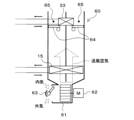
- FIG. 1 is a schematic configuration diagram of an indoor air conditioning unit according to a first embodiment
- FIG. 2 is a block diagram showing a control system of the heat pump system according to the first embodiment
- FIG. It is an explanatory view showing a functional composition of a temperature control control part concerning a 1st embodiment
- 4 is a flowchart relating to a heat quantity adjustment program during heating operation according to the first embodiment.
- FIG. 5 is an explanatory diagram showing the relationship between the traveling speed of a vehicle and the upper limit value of the rotation speed of a compressor;
- FIG. 1 is an overall configuration diagram of a heat pump system according to a first embodiment
- FIG. 1 is a schematic configuration diagram of an indoor air conditioning unit according to a first embodiment
- FIG. 2 is a block diagram showing a control system of the heat pump system according to the first embodiment
- FIG. It is an explanatory view showing a functional composition of a temperature control control part
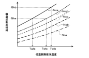
- FIG. 4 is a characteristic diagram showing the relationship between the rotation speed of the compressor, the heat transfer amount on the high temperature side, and the temperature of the heat medium on the low temperature side.
- FIG. 4 is a characteristic diagram showing the relationship between the rotation speed of the compressor, the amount of heat transfer on the low temperature side, and the temperature of the low temperature heat medium.
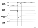
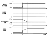
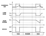
- FIG. 5 is an explanatory diagram showing an example of an operating state when a heating request changes; It is an explanatory view showing an example of heating operation by the heat pump system concerning a 1st embodiment.
- 9 is a flow chart relating to a heat quantity adjustment program during heating operation according to the second embodiment.
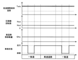
- FIG. 4 is an explanatory diagram showing an example of an operating state when a target value for heating operation is changed in accordance with changes in running conditions of the vehicle;
- FIG. 4 is an explanatory diagram showing an example of an operating state when a target value for heating operation is determined with reference to a stopped state of the vehicle; It is explanatory drawing which shows an example of the heating operation by the heat pump system which concerns on 3rd Embodiment.
- FIG. 11 is an explanatory diagram regarding calculation of a preparation period in the third embodiment;
- FIG. 14 is a flow chart relating to a prediction function setting program in the fourth embodiment;
- FIG. FIG. 5 is an explanatory diagram showing an example of an operation state when heating operation is started from a heating stop state; It is explanatory drawing which shows an example of the heating operation by the heat pump system which concerns on 4th Embodiment.
- FIG. 1st Embodiment A first embodiment of the present disclosure will be described with reference to FIGS. 1 to 10.
- FIG. 1st Embodiment the heat pump system 1 which concerns on this indication is applied to the vehicle A.
- the vehicle A is a BEV (Battery Electric Vehicle) that is equipped with a battery for running and runs on electric power from the battery.
- BEV Battery Electric Vehicle
- the heat pump system 1 adjusts the temperature of the air conditioning, battery, and heat-generating equipment 46 in the vehicle interior, which is the space to be air-conditioned, in the electric vehicle.
- the heat pump system 1 can switch between a cooling mode, a heating mode, and a dehumidifying heating mode as air conditioning operation modes for air conditioning the vehicle interior.
- the cooling mode is an operation mode in which the air blown into the passenger compartment is cooled and blown out into the passenger compartment.
- the heating mode is an operation mode in which the blown air is heated and blown into the passenger compartment.
- the dehumidification/heating mode is an operation mode in which dehumidification/heating of the interior of the vehicle is performed by reheating cooled and dehumidified blast air and blowing the air into the interior of the vehicle.
- the heat pump cycle 10 of the heat pump system 1 employs an HFO-based refrigerant (specifically, HFO1234yf) as a refrigerant, and constitutes a subcritical refrigeration cycle in which the pressure of the refrigerant on the high-pressure side does not exceed the critical pressure of the refrigerant.
- Refrigerant oil for lubricating the compressor 11 is mixed in the refrigerant.
- PAG oil polyalkylene glycol oil
- Some of the refrigerating machine oil circulates through the cycle together with the refrigerant.
- FIG. A heat pump system 1 according to the first embodiment has a heat pump cycle 10 , a heating section 30 , a low temperature side heat medium circuit 40 , an indoor air conditioning unit 60 and an energy manager 70 .
- the heat pump cycle 10 is a vapor compression refrigeration cycle device.
- the compressor 11 sucks, compresses, and discharges the refrigerant.
- Compressor 11 is located in the vehicle hood.
- the compressor 11 is an electric compressor in which an electric motor rotates a fixed displacement compression mechanism with a fixed displacement.
- the compressor 11 has its rotational speed (that is, refrigerant discharge capacity) controlled by a control signal output from an energy manager 70, which will be described later.
- a rotational speed upper limit value Ncul is set for the compressor 11, and is determined such that the higher the traveling speed of the vehicle A is, the higher the rotational speed upper limit value Ncul is. This point will be described later.
- a discharge port of the compressor 11 is connected to an inlet side of a refrigerant passage 12 a in the heat medium refrigerant heat exchanger 12 .
- the heat medium refrigerant heat exchanger 12 radiates the heat of the high pressure refrigerant discharged from the compressor 11 to the high temperature side heat medium circulating in the high temperature side heat medium circuit 31 of the heating unit 30, thereby heating the high temperature side heat medium. It is a heat exchanger that
- the heat medium refrigerant heat exchanger 12 has a refrigerant passage 12a through which the refrigerant of the heat pump cycle 10 flows, and a heat medium passage 12b through which the high temperature side heat medium of the high temperature side heat medium circuit 31 flows.
- the heat medium/refrigerant heat exchanger 12 is made of the same kind of metal (aluminum alloy in the first embodiment) with excellent heat transfer properties, and each constituent member is integrated by brazing.
- the heat medium-refrigerant heat exchanger 12 is an example of a condenser that dissipates the heat of the high-pressure refrigerant, and constitutes a part of the heating section 30, which will be described later.
- a first connecting portion 13a having a three-way joint structure is connected to the outlet of the refrigerant passage 12a of the heat medium refrigerant heat exchanger 12.
- the first connecting portion 13a one of the three inflow/outlet ports is used as a coolant inflow port, and the remaining two are used as coolant outflow ports. That is, the first connection portion 13 a is a branch portion that branches the flow of the liquid-phase refrigerant that has flowed out of the heat medium refrigerant heat exchanger 12 .
- the refrigerant inlet side of the air-conditioning evaporator 15 is connected to one refrigerant outlet port of the first connection portion 13a via the first expansion valve 14a.
- the refrigerant inlet side of the chiller 16 is connected to the other refrigerant outlet port of the refrigerant branch portion via the second expansion valve 14b.
- the first expansion valve 14a reduces the pressure of the refrigerant flowing out of one of the refrigerant outlets of the first connecting portion 13a at least in the operation mode for cooling the blown air.
- the first expansion valve 14a is an electric variable throttle mechanism, and has a valve body and an electric actuator.
- the first expansion valve 14a is composed of a so-called electric expansion valve.
- the valve element of the first expansion valve 14a is configured to be able to change the passage opening (in other words, throttle opening) of the refrigerant passage.
- the electric actuator has a stepping motor that changes the throttle opening of the valve body.
- the operation of the first expansion valve 14 a is controlled by a control signal output from the energy manager 70 .
- the first expansion valve 14a is composed of a variable throttle mechanism having a full-opening function of fully opening the refrigerant passage when the throttle opening is fully opened and a full-closing function of closing the refrigerant passage when the throttle opening is fully closed. It is In other words, the first expansion valve 14a can prevent the refrigerant from decompressing by fully opening the refrigerant passage.
- the first expansion valve 14a can block the inflow of the refrigerant to the air-conditioning evaporator 15 by closing the refrigerant passage. That is, the first expansion valve 14a has both a function as a decompression section that decompresses the refrigerant and a function as a refrigerant circuit switching section that switches the refrigerant circuit. Further, the first expansion valve 14a can adjust the flow rate of the refrigerant flowing into the air-conditioning evaporator 15 by adjusting the opening degree of the refrigerant passage.
- the refrigerant inlet side of the air-conditioning evaporator 15 is connected to the outlet of the first expansion valve 14a. As shown in FIG. 2 , the air-conditioning evaporator 15 is arranged inside a casing 61 of the indoor air-conditioning unit 60 . The air-conditioning evaporator 15 performs heat exchange between the low-pressure refrigerant decompressed by the first expansion valve 14a and the blown air to evaporate the low-pressure refrigerant and cool the blown air at least in the operation mode for cooling the blown air.
- the second expansion valve 14b is connected to the other refrigerant outlet port of the first connection portion 13a.
- the second expansion valve 14b reduces the pressure of the refrigerant flowing out of the other refrigerant outlet port of the first connection portion 13a at least in the heating mode.
- the second expansion valve 14b is an electric variable throttle mechanism, and has a valve element and an electric actuator. That is, the second expansion valve 14b is composed of a so-called electric expansion valve and has a fully open function and a fully closed function.
- the second expansion valve 14b can prevent the refrigerant from decompressing by fully opening the refrigerant passage. Further, the second expansion valve 14b can block the inflow of the refrigerant to the chiller 16 by closing the refrigerant passage. That is, the second expansion valve 14b has both a function as a decompression section that decompresses the refrigerant and a function as a refrigerant circuit switching section that switches the refrigerant circuit.
- the second expansion valve 14b is an example of a decompression section.
- the refrigerant inlet side of the chiller 16 is connected to the outlet of the second expansion valve 14b.
- the chiller 16 is a heat exchanger that exchanges heat between the low-pressure refrigerant decompressed by the second expansion valve 14 b and the low-temperature side heat medium circulating in the low-temperature side heat medium circuit 40 .
- the chiller 16 has a refrigerant passage 16a through which the low-pressure refrigerant decompressed by the second expansion valve 14b flows, and a heat medium passage 16b through which the low temperature side heat medium circulating in the low temperature side heat medium circuit 40 flows. . Therefore, the chiller 16 is an evaporator that evaporates the low-pressure refrigerant and absorbs heat from the low-temperature side heat medium by heat exchange between the low-pressure refrigerant flowing through the refrigerant passage 16a and the low-temperature side heat medium flowing through the heat medium passage 16b. That is, the chiller 16 corresponds to an example of an evaporator.
- one refrigerant inlet side of the second connecting portion 13b is connected to the refrigerant outlet of the air-conditioning evaporator 15.
- the refrigerant outlet side of the chiller 16 is connected to the other refrigerant inlet side of the second connecting portion 13b.
- the second connecting portion 13b has a three-way joint structure similar to that of the first connecting portion 13a, with two of the three inflow/outlets serving as coolant inlets and the remaining one serving as a coolant outlet.
- the second connection portion 13b is a confluence portion where the flow of refrigerant flowing out of the air-conditioning evaporator 15 and the flow of refrigerant flowing out of the chiller 16 are merged.
- the suction port side of the compressor 11 is connected to the refrigerant outlet of the second connection portion 13b.
- the heating unit 30 is configured to use the high-pressure refrigerant in the heat pump cycle 10 as a heat source to heat the blown air supplied to the air-conditioned space.
- the heating unit 30 is composed of the high-temperature side heat medium circuit 31 .
- the high-temperature-side heat medium circuit 31 is a heat-medium circuit for circulating a high-temperature-side heat medium, and as the high-temperature-side heat medium, a solution containing ethylene glycol, antifreeze, or the like can be used.
- the high temperature side heat medium circuit 31 includes a heat medium passage 12b of the heat medium refrigerant heat exchanger 12, a high temperature side pump 32, a heater core 33, a high temperature side outside air heat exchanger 34, and a high temperature side flow control valve. 35, a high temperature side heater 36 and the like are arranged.
- the high temperature side heat medium is heated by heat exchange with the high pressure refrigerant flowing through the refrigerant passage 12a. That is, the high temperature side heat medium is heated using the heat pumped up by the heat pump cycle 10 .
- a discharge port of the high temperature side pump 32 is connected to the inlet side of the heat medium passage 12 b of the heat medium refrigerant heat exchanger 12 .
- the high temperature side pump 32 is a heat medium pump that pumps the high temperature side heat medium to circulate in the high temperature side heat medium circuit 31 .
- the high temperature side pump 32 is an electric pump whose number of revolutions (that is, pumping capacity) is controlled by a control voltage output from the energy manager 70 .
- a high temperature side heater 36 is connected to the outlet side of the heat medium passage 12 b of the heat medium refrigerant heat exchanger 12 .
- the high temperature side heater 36 generates heat by being supplied with electric power, and heats the high temperature side heat medium flowing through the heat medium passage of the high temperature side heater 36 .
- a PTC heater having a PTC element that is, a positive temperature coefficient thermistor
- the high temperature side heater 36 can arbitrarily adjust the amount of heat for heating the high temperature side heat medium by the control voltage output from the energy manager 70 .
- the inlet of the high temperature side flow control valve 35 is connected to the outlet side of the heat medium passage in the high temperature side heater 36 .
- the high temperature side flow control valve 35 is composed of an electric three-way flow control valve having three inlets and outlets.
- the inlet of the heater core 33 is connected to one outlet of the high temperature side flow control valve 35 .
- the heater core 33 is a heat exchanger that heats the air that has passed through the air-conditioning evaporator 15 and the high-temperature side heat medium heated by the heat medium-refrigerant heat exchanger 12 or the like, thereby heating the air.
- the heater core 33 is arranged inside a casing 61 of the indoor air conditioning unit 60 . Therefore, the heater core 33 corresponds to an example of a heating heat exchanger.
- the other outflow port of the high temperature side flow control valve 35 is connected to the inflow port of the high temperature side outside air heat exchanger 34 .
- the high temperature side outside air heat exchanger 34 exchanges heat between the high temperature side heat medium heated by the heat medium/refrigerant heat exchanger 12 and the outside air OA, and radiates the heat of the high temperature side heat medium to the outside air OA.
- the high temperature side outside air heat exchanger 34 is arranged on the front side inside the vehicle hood. As the vehicle A travels, the outside air OA flows rearward from the front side of the vehicle and passes through the heat exchange portion of the high temperature side outside air heat exchanger 34 . Therefore, the high-temperature side outside air heat exchanger 34 can utilize the running wind to radiate heat to the outside air OA.
- a high temperature side confluence portion having a three-way joint structure is connected to the outflow port of the high temperature side outside air heat exchanger 34 and the outflow port of the heater core 33 .
- the high-temperature side junction has one of the three inlets and outlets in the three-way joint structure as an outlet and the remaining two as inlets. Therefore, the high-temperature side confluence section can join the flow of the high-temperature side heat medium that has passed through the high-temperature side outside air heat exchanger 34 and the flow of the high-temperature side heat medium that has passed through the heater core 33 .
- a suction port of the high temperature side pump 32 is connected to the outflow port of the high temperature side confluence portion.
- the high temperature side heat control valve 35 adjusts the flow rate of the high temperature side heat medium flowing into the heater core 33 side and the flow rate of the high temperature side heat medium flowing into the high temperature side outside air heat exchanger 34. The flow rate can be adjusted continuously.
- the heat amount of the high temperature side heat medium radiated to the outside air OA by the high temperature side outside air heat exchanger 34 and the heat amount of the high temperature side heat medium radiated to the blast air by the heater core 33 can be adjusted.
- the low temperature side heat medium circuit 40 is a heat medium circuit that circulates the low temperature side heat medium.
- the same fluid as the high temperature side heat medium in the high temperature side heat medium circuit 31 can be used as the low temperature side heat medium.
- the low temperature side heat medium circuit 40 includes a heat medium passage 16b of the chiller 16, a low temperature side pump 41, a battery heat exchange section 42, a low temperature side outside air heat exchanger 43, a low temperature side flow control valve 44, a low temperature side heater 45, and heat generation.
- a device 46, a shutter device 47, and the like are arranged.
- the discharge port side of the low temperature side pump 41 is connected to the inlet of the heat medium passage 16 b in the chiller 16 .
- the low temperature side pump 41 is a heat medium pump that pumps the low temperature side heat medium to the heat medium passage 16 b of the chiller 16 in the low temperature side heat medium circuit 40 .
- the basic configuration of the low temperature side pump 41 is similar to that of the high temperature side pump 32 . Since it is possible to adjust the flow rate of the low-temperature side heat medium passing through the chiller 16 and the like, the low-temperature side pump 41 corresponds to an example of a heat amount adjustment section.
- the outlet of the heat medium passage 16 b of the chiller 16 is connected to the inlet side of the heat medium passage of the heat generating device 46 .
- the heat-generating device 46 is configured by, among the on-vehicle devices mounted on the vehicle A, a device that generates heat accompanying an operation for the purpose of running or the like.
- the heat generating device 46 corresponds to an example of a heat source device.
- the heat generating device 46 includes an inverter INV and a motor generator MG.
- the heat medium passage of the heat-generating device 46 is formed so as to cool each constituent device by circulating the heat medium.
- the inverter INV is a power converter that converts direct current to alternating current.
- the motor-generator MG When supplied with electric power, the motor-generator MG outputs driving force for traveling, and generates regenerative electric power during deceleration and the like.
- a transaxle device is a device that integrates a transmission, a final gear, and a differential gear (differential gear).
- the inlet side of the heat medium passage 42 a of the battery heat exchange section 42 is connected to the outlet side of the heat medium passage in the heat generating device 46 .
- the battery heat exchange unit 42 is connected to the low temperature heat medium circuit 40 so as to be cooled by the low temperature heat medium, and is configured to maintain the temperature of the battery within a predetermined temperature range. Specifically, the low-temperature side heat medium is caused to pass through the heat medium passage 42a of the battery heat exchange portion 42 for heat exchange, so that the heat generated in the battery is absorbed by the low-temperature side heat medium, and the temperature of the battery is adjusted. It is carried out.
- the battery heat exchange unit 42 and the battery correspond to an example of a heat source device.
- the battery supplies power to various electric devices of the vehicle A, and for example, a rechargeable secondary battery (lithium ion battery in this embodiment) is adopted.
- a battery generates heat during charging and discharging.
- a battery is a so-called assembled battery formed by stacking a plurality of battery cells and electrically connecting the battery cells in series or in parallel. This type of battery tends to reduce its output when the temperature drops, and tends to deteriorate when the temperature rises.
- the temperature of the battery must be maintained within an appropriate temperature range (for example, 10°C or higher and 40°C or lower) in which the charge/discharge capacity of the battery can be fully utilized. Therefore, in the heat pump system 1 , the temperature of the battery is appropriately adjusted by controlling the flow rate of the low-temperature side heat medium flowing through the battery heat exchange section 42 .
- a low temperature side flow control valve 44 is connected to the outlet side of the heat medium passage 42 a of the battery heat exchange section 42 .
- the low temperature side flow control valve 44 is composed of an electric three-way flow control valve having three inlets and outlets. As shown in FIG. 1 , the inlet of the low-temperature side flow control valve 44 is connected to the outlet side of the heat medium passage 42 a of the battery heat exchange section 42 .
- the low temperature side outside air heat exchanger 43 is a heat exchanger that exchanges heat between the low temperature side heat medium circulating in the low temperature side heat medium circuit 40 and the outside air OA blown by the outside air fan 43a. Also, the low-temperature side outside air heat exchanger 43 is arranged on the front side in the driving device room. Therefore, when the vehicle is running, the low temperature side outside air heat exchanger 43 can be exposed to running wind.
- a low temperature side heater 45 is connected to the outlet of the low temperature side outside air heat exchanger 43 .
- the low temperature side heater 45 generates heat when supplied with electric power, and heats the low temperature side heat medium flowing through the heat medium passage of the low temperature side heater 45 .
- the low temperature side heater 45 corresponds to an example of a heat source device.
- a PTC heater can be used as the low-temperature side heater 45, like the high-temperature side heater 36.
- the low temperature side heater 45 can arbitrarily adjust the amount of heat for heating the high temperature side heat medium by the control voltage output from the energy manager 70 .
- the suction port side of the low temperature side pump 41 is connected to the outflow port of the heat medium passage in the low temperature side heater.
- the other outlet port of the low temperature side flow control valve 44 is connected to one end of a bypass flow path through which the low temperature side heat medium flows so as to bypass the low temperature side outside air heat exchanger 43 .
- a confluence portion of a three-way joint structure is connected to the other end of the bypass channel. The confluence part uses two of the three inlets and outlets in the three-way joint structure as inlets and the remaining one as an outlet.
- the confluence portion is arranged in the heat medium flow path connecting the outlet of the low temperature side outside air heat exchanger 43 and the inlet of the low temperature side heater 45 . Therefore, the confluence portion joins the flow of the low-temperature side heat medium that has flowed through the low-temperature side outside air heat exchanger 43 and the flow of the low-temperature side heat medium that has flowed through the bypass passage, and flows into the suction port side of the low-temperature side pump 41 . let it flow.
- the low temperature side flow control valve 44 controls the flow rate of the low temperature side heat medium passing through the low temperature side outside air heat exchanger 43 and the low temperature side outside air flow rate for the flow of the low temperature side heat medium passing through the heat medium passage 16b of the chiller 16.
- the flow rate ratio with the flow rate of the low temperature side heat medium bypassing the heat exchanger 43 can be continuously adjusted. That is, the low temperature side heat medium circuit 40 can switch the flow of the low temperature side heat medium by controlling the operation of the low temperature side flow control valve 44 .
- the low-temperature side flow control valve 44 corresponds to an example of a heat quantity control section.
- an outside air fan 43 a and a shutter device 47 are arranged as devices for the low temperature side outside air heat exchanger 43 .
- the outside air fan 43 a is arranged to blow the outside air OA to the low temperature side outside air heat exchanger 43 .
- the outside air fan 43 a is an electric blower whose number of revolutions (that is, blowing capacity) is controlled by a control voltage output from the energy manager 70 . That is, since the outside air fan 43a can adjust the wind speed (air volume) of the outside air to the low temperature side outside air heat exchanger 43, it can be used to adjust the amount of heat for the low temperature side heat medium.
- the outside air fan 43a corresponds to an example of the heat quantity adjusting section.
- a shutter device 47 is arranged on the vehicle front side of the low temperature side outside air heat exchanger 43 .
- the shutter device 47 is configured by rotatably arranging a plurality of blades in an opening of a frame-like frame. The plurality of blades are rotated in conjunction with the operation of an electric actuator (not shown) to adjust the opening area of the opening of the frame.
- the shutter device 47 can adjust the flow rate of the outside air OA passing through the low temperature side outside air heat exchanger 43 and adjust the heat exchange capacity of the low temperature side outside air heat exchanger 43 . Therefore, the shutter device 47 corresponds to an example of a heat quantity adjusting section.
- the indoor air conditioning unit 60 that constitutes the heat pump system 1 will be described with reference to FIG.
- the indoor air conditioning unit 60 is a unit for blowing off the blown air temperature-controlled by the heat pump cycle 10 to appropriate locations in the vehicle interior.
- the interior air-conditioning unit 60 is arranged inside the instrument panel (that is, the instrument panel) at the forefront of the vehicle interior.
- the indoor air-conditioning unit 60 is configured by housing a blower 62, an air-conditioning evaporator 15, a heater core 33, etc. in an air passage formed inside a casing 61 that forms an outer shell thereof.
- the casing 61 forms an air passage for air blown into the passenger compartment.
- the casing 61 is molded from a resin (specifically, polypropylene) having a certain degree of elasticity and excellent strength.
- an inside/outside air switching device 63 is arranged on the most upstream side of the blowing air flow of the casing 61 .
- the inside/outside air switching device 63 switches and introduces inside air (vehicle interior air) and outside air (vehicle exterior air) into the casing 61 .
- the inside/outside air switching device 63 continuously adjusts the opening areas of the inside air introduction port for introducing the inside air into the casing 61 and the outside air introduction port for introducing the outside air into the casing 61 by means of the inside/outside air switching door, thereby adjusting the amount of the inside air introduced and the amount of the outside air. Change the introduction ratio with the introduction air volume.
- the inside/outside air switching door is driven by an electric actuator for inside/outside air switching door. The operation of this electric actuator is controlled by a control signal output from the energy manager 70 .
- a blower 62 is arranged downstream of the inside/outside air switching device 63 in the blown air flow.
- the blower 62 is an electric blower that drives a centrifugal multi-blade fan with an electric motor.
- the blower 62 blows the air sucked through the inside/outside air switching device 63 into the vehicle interior.
- the blower 62 has its rotation speed (that is, blowing capacity) controlled by the control voltage output from the energy manager 70 .
- the air-conditioning evaporator 15 and the heater core 33 are arranged in this order with respect to the flow of the blown air on the downstream side of the blown air flow of the blower 62 . That is, the air-conditioning evaporator 15 is arranged upstream of the heater core 33 in the blown air flow. Therefore, in the indoor air conditioning unit 60 of the heat pump system 1 , the heater core 33 can heat at least part of the blown air that has passed through the air conditioning evaporator 15 .
- a cold air bypass passage 65 is also formed in the casing 61 .
- the cold-air bypass passage 65 is an air passage through which the blown air that has passed through the air-conditioning evaporator 15 bypasses the heater core 33 and flows downstream.
- An air mix door 64 is arranged on the downstream side of the air-conditioning evaporator 15 in the blown air flow and upstream of the heater core 33 in the blown air flow.
- the air mix door 64 adjusts the ratio of the amount of air passing through the heater core 33 and the amount of air passing through the cold air bypass passage 65 in the air that has passed through the air conditioning evaporator 15 .
- the air mix door 64 is driven by an electric actuator for driving the air mix door.
- the operation of this electric actuator is controlled by a control signal output from the energy manager 70 .
- a mixing space is provided on the downstream side of the heater core 33 in the blown air flow. In the mixing space, the blast air heated by the heater core 33 and the blast air that has passed through the cold air bypass passage 65 and is not heated by the heater core 33 are mixed.
- an opening hole is arranged to blow out the blown air (air-conditioned air) mixed in the mixing space into the vehicle interior.
- the openings include a face opening, a foot opening, and a defroster opening (all not shown).
- the face opening hole is an opening hole for blowing air conditioning air toward the upper body of the passenger inside the vehicle.
- the foot opening hole is an opening hole for blowing the conditioned air toward the passenger's feet.
- the defroster opening hole is an opening hole for blowing the conditioned air toward the inner surface of the window glass on the front of the vehicle.
- face opening hole, foot opening hole, and defroster opening hole are connected to the face outlet, foot outlet, and defroster outlet (none of which are shown) provided in the passenger compartment via ducts that form air passages. )It is connected to the.
- the air mix door 64 adjusts the air volume ratio between the air volume passing through the heater core 33 and the air volume passing through the cold air bypass passage 65, thereby adjusting the temperature of the conditioned air mixed in the mixing space. As a result, the temperature of the blown air (air-conditioned air) blown into the vehicle interior from each outlet is also adjusted.
- a face door, a foot door, and a defroster door are arranged on the upstream sides of the face opening hole, the foot opening hole, and the defroster opening hole, respectively.
- the face door adjusts the opening area of the face opening hole.
- the foot door adjusts the opening area of the foot opening hole.
- the defroster door adjusts the opening area of the defroster opening hole.
- the face door, foot door, and defroster door constitute a blowout mode switching device that switches the blowout port from which the conditioned air blows out.
- the face door, foot door, and defroster door are connected to an electric actuator for driving the outlet mode door via a link mechanism or the like, and are rotated in conjunction with each other. The operation of this electric actuator is controlled by a control signal output from the energy manager 70 .
- the energy manager 70 controls the operation of each device constituting the vehicle A including the heat pump system 1 .
- the energy manager 70 has a temperature control control section 71 , an exercise manager 80 , an air conditioning manager 81 , a high temperature side manager 82 , a cycle manager 83 , a low temperature side manager 84 and an information notification section 85 .
- the energy manager 70 is implemented by an in-vehicle computer that includes a processing unit, RAM, storage unit, input/output interface, and a bus that connects them.
- the processing unit is hardware for arithmetic processing coupled with RAM. By accessing the RAM, the processing unit executes various processes for realizing the functions of each functional unit, which will be described later.
- the storage unit is configured to include a nonvolatile storage medium. The storage unit stores various programs (calorie adjustment program, etc.) executed by the processing unit. A specific configuration and functional units of the energy manager 70 will be described later in detail.
- the vehicle A is equipped with a communication module 90, a navigation device 91, a user input unit 92, a plurality of consumption domains DEc, and the like.
- the communication module 90 is a communication module (Data Communication Module) mounted on the vehicle A.
- the communication module 90 transmits and receives radio waves to and from base stations around the vehicle A through wireless communication conforming to communication standards such as LTE (Long Term Evolution) and 5G.
- LTE Long Term Evolution
- 5G wireless communication conforming to communication standards
- the communication module 90 can transmit and receive information with the cloud server 100 and the like through the network NW.
- the cloud server 100 is an information distribution server installed on the cloud, and distributes weather information, road traffic information, and the like, for example.
- the navigation device 91 is an in-vehicle device that guides the travel route to the destination set by the user.
- the navigation device 91 guides the vehicle to go straight, turn left or right, change lanes, etc. at intersections, branch points, merging points, etc., through screen display, voice reproduction, and the like.
- the navigation device 91 can provide the energy manager 70 with information such as the distance to the destination, the vehicle speed in each traveling section, and the difference in elevation as navigation information, as environment information.
- the driving route may include sections with different speed ranges, such as general roads and highways. Since the legal speed limit on expressways is higher than the legal speed limit on general roads, it is assumed that the battery output required for driving on expressways will be greater than for driving on general roads. .
- a travel route may include a travel section composed of plains and a travel section composed of mountainous areas.
- the running section running in the mountainous area consists of a running section that climbs a slope with a certain degree of inclination or more. expected to be larger than
- the user input unit 92 is an operation device that receives an input operation by a user who is an occupant of the vehicle A.
- the user input unit 92 receives, for example, a user operation for operating the navigation device 91, a user operation for switching between enabling and disabling the heating prediction, a user operation for changing various setting values related to the vehicle A, and the like.
- the user input unit 92 can provide the energy manager 70 with input information based on user operations.
- a steering switch provided on the spokes of the steering wheel, switches and dials provided on the center console, etc., and a voice input device for detecting the driver's speech are mounted as the user input unit 92 on the vehicle A.
- a touch panel or the like of the navigation device 91 may function as the user input section 92 .
- a user terminal such as a smart phone and a tablet terminal may function as the user input unit 92 by being connected to the energy manager 70 by wire or wirelessly.
- the consumption domain is a group of in-vehicle devices that realize various vehicle functions by using power such as batteries.
- One consumption domain includes at least one domain manager and is composed of a group of in-vehicle devices whose power consumption is managed by the domain manager.
- the multiple consumption domains include a running control domain and a temperature control domain.
- the travel control domain is a consumption domain that controls the travel of vehicle A.
- the cruise control domain includes motor generator MG, inverter INV, steering control system SCS, brake control system BCS, and motion manager 80 .
- the motor generator MG is a driving source that generates a driving force for running the vehicle A.
- the inverter INV controls power running and regeneration by the motor generator MG.
- a steering control system SCS controls the steering of the vehicle A.
- the brake control system BCS controls the braking force applied to the vehicle A.
- the inverter INV converts the DC power supplied from the battery into three-phase AC power during power running by the motor generator MG, and supplies the three-phase AC power to the motor generator MG. Inverter INV can adjust the frequency, current and voltage of AC power, and controls the driving force generated by motor generator MG. On the other hand, during regeneration by motor generator MG, inverter INV converts AC power into DC power and supplies it to the battery.
- the motion manager 80 comprehensively controls the inverter INV, the steering control system SCS, and the brake control system BCS, and makes the vehicle A run in accordance with the driving operation of the driver.
- the motion manager 80 functions as a domain manager of the running control domain and comprehensively manages power consumption by each of the motor generator MG, the inverter INV, the steering control system SCS and the brake control system BCS.
- the exercise manager 80 also has a power transmission control section 80a.
- the power transmission control unit 80a controls the running of the vehicle A by integrally controlling the inverter INV, the steering control system SCS, and the brake control system BCS.
- the temperature control domain is a consumption domain that performs air conditioning of the cabin space of vehicle A and temperature adjustment of the battery.
- the temperature control domain includes a consumption domain related to the indoor air conditioning unit 60 , a consumption domain related to the high temperature side heat medium circuit 31 , a consumption domain related to the heat pump cycle 10 , and a consumption domain related to the low temperature side heat medium circuit 40 .
- the consumption domain related to the indoor air conditioning unit 60 includes the components of the indoor air conditioning unit 60 and the air conditioning manager 81 .
- Components of the indoor air conditioning unit 60 include a blower 62, an inside/outside air switching device 63, an electric actuator for an air mix door 64, and the like.
- the air-conditioning manager 81 is a domain manager related to the components of the indoor air-conditioning unit 60, and comprehensively controls each component to realize an air-conditioned environment desired by the user.
- the air-conditioning control unit 81a adjusts the air volume of the conditioned air and the proportion of the inside and outside air in the conditioned air, and comprehensively manages the power consumption of each component in the indoor air-conditioning unit 60 .
- the consumption domain for the high temperature side heat medium circuit 31 includes the high temperature side pump 32 , the high temperature side flow control valve 35 , the high temperature side heater 36 and the high temperature side manager 82 .
- the high temperature side manager 82 is a domain manager related to the components of the high temperature side heat medium circuit 31, and controls the flow of the high temperature side heat medium in the high temperature side heat medium circuit 31 to a desired state.
- the high temperature side manager 82 has a circuit control section 82a, and the circuit control section 82a controls the pumping capability of the high temperature side heat medium in the high temperature side pump 32, the flow rate balance in the high temperature side flow control valve 35, and the The heating amount of the high temperature side heat medium is controlled.
- the high temperature side manager 82 receives a high temperature side heat medium temperature Twh, which is the temperature of the high temperature side heat medium circulating in the high temperature side heat medium circuit 31, from a plurality of temperature sensors arranged in the high temperature side heat medium circuit 31. be done. Therefore, the high temperature side manager 82 can control the amount of heat generated by the high temperature side heater 36 using the detected high temperature side heat medium temperature Twh.
- Twh the high temperature side heat medium temperature
- the consumption domain for the heat pump cycle 10 includes the compressor 11, the first expansion valve 14a, the second expansion valve 14b, and the cycle manager 83.
- the cycle manager 83 is a domain manager related to the components of the heat pump cycle 10 and controls the state of the refrigerant circulating through the heat pump cycle 10 to a desired state.
- the cycle manager 83 has a circuit control unit 83a, and the circuit control unit 83a controls the refrigerant discharge capacity (rotational speed) of the compressor 11, the amount of pressure reduction in the first expansion valve 14a, and the amount of pressure reduction in the second expansion valve 14b. is controlled.
- the cycle manager 83 also receives detection results regarding the refrigerant temperature and refrigerant pressure from the refrigerant temperature sensor and the refrigerant pressure sensor arranged in the heat pump cycle 10 . Therefore, the cycle manager 83 can adjust the rotational speed of the compressor 11, the throttle opening of the first expansion valve 14a, etc., using the detected refrigerant temperature and refrigerant pressure values.
- the consumption domain for the low temperature side heat medium circuit 40 includes the low temperature side pump 41 , the low temperature side flow control valve 44 , the low temperature side heater 45 , the shutter device 47 and the low temperature side manager 84 .
- the low temperature side manager 84 is a domain manager related to the components of the low temperature side heat medium circuit 40, and controls the flow of the low temperature side heat medium in the low temperature side heat medium circuit 40 to a desired state.
- the low temperature side manager 84 has a circuit control section 84a, and the circuit control section 84a controls the pumping capability of the low temperature side heat medium in the low temperature side pump 41, the flow rate balance in the low temperature side flow control valve 44, and the like. Further, the circuit control unit 84 a controls the heating amount of the low temperature side heat medium in the low temperature side heater 45 and the opening area of the shutter device 47 .
- the low-temperature side heat medium temperature Twl which is the temperature of the low-temperature side heat medium circulating in the low-temperature side heat medium circuit 40, is input to the low-temperature side manager 84 by a plurality of temperature sensors arranged in the low-temperature side heat medium circuit 40. be done. Therefore, the low temperature side manager 84 can control the amount of heat generated by the low temperature side heater 45, etc., using the detected low temperature side heat medium temperature Twl.
- At least one of the temperature sensors for detecting the low-temperature side heat medium temperature Twl is arranged on the inlet side of the heat medium passage 16b of the chiller 16, and the low-temperature side heat medium flowing into the chiller 16 is Detect the temperature Twl.
- the energy manager 70 includes a temperature control section 71, an exercise manager 80, an air conditioning manager 81, a high temperature side manager 82, a cycle manager 83, a low temperature side manager 84, and an information notification section 85.
- the battery manager, the motion manager 80, and the heat manager are on-board computers that control specific functions (for example, the running function and the temperature control function of the vehicle), and constitute a part of the energy manager 70. ing.
- the temperature regulation control unit 71 uses various information output from the battery manager, the exercise manager 80, and the heat manager to integrally manage power usage by each consumption domain.
- the temperature control unit 71 is configured by an in-vehicle computer and constitutes a part of the energy manager 70 .
- the temperature control section 71 plays a major role in control processing in the energy manager 70 .
- the information notification unit 85 is an in-vehicle computer that functions as a domain manager for notifying various information acquired from the cloud server 100 or the like, and constitutes a part of the energy manager 70 .
- a consumption domain for notifying the user of the vehicle A of information is connected to the information notification unit 85 .
- the display and speaker of the navigation device 91 the display unit arranged on the instrument panel (that is, the instrument panel) at the forefront of the vehicle compartment, and the like are connected to the information notification unit 85 .
- the information notification section 85 can display the information specified by the temperature control section 71 on the display of the navigation device 91 or the like. Further, the information notification unit 85 can output the information specified by the temperature control control unit 71 by voice from the speaker of the navigation device 91 .
- the display, speaker, etc. of the navigation device 91 correspond to an example of the information transmission section.
- the power supply to the energy manager 70 which is an in-vehicle computer, is continued even when the vehicle A is in a non-drivable state (for example, the ignition is off). Therefore, the energy manager 70 can activate each functional unit and execute a predetermined process even during the idle period if control execution is necessary.
- the heat pump system 1 is provided with a group of control sensors so that the heat pump system 1 can appropriately perform the air-conditioning operation and the device temperature control operation.
- the energy manager 70 is connected to a group of control sensors for controlling devices to be controlled in the heat pump system 1 .
- the control sensor group includes an inside air temperature sensor, an outside air temperature sensor, a solar radiation sensor, a high pressure sensor, an evaporator temperature sensor, and a junction pressure sensor.
- the inside air temperature sensor is an inside air temperature detection unit that detects the temperature inside the vehicle (inside air temperature) Tr.
- the outside air temperature sensor is an outside air temperature detection unit that detects the vehicle outside temperature (outside air temperature) Tam.
- a solar radiation sensor is a solar radiation amount detection part which detects the solar radiation amount As irradiated to a vehicle interior.
- the high-pressure sensor is a refrigerant pressure detector that detects the high-pressure refrigerant pressure Pd in the refrigerant flow path from the discharge port side of the compressor 11 to the inlet side of the first expansion valve 14a or the second expansion valve 14b.
- the evaporator temperature sensor is an evaporator temperature detection unit that detects the refrigerant evaporation temperature (evaporator temperature) Tefin in the air conditioning evaporator 15 .
- the confluence pressure sensor is a refrigerant pressure detector that detects the refrigerant pressure in the second connection portion 13b of the heat pump cycle 10 .
- the junction pressure indicates the refrigerant pressure on the low pressure side of the heat pump cycle 10 .
- control sensor group includes a battery temperature sensor, a blown air temperature sensor, and an intake air temperature sensor.
- the battery temperature sensor is a battery temperature detection unit that detects battery temperature, which is the temperature of the battery.
- the battery temperature sensor has a plurality of temperature detection units and detects temperatures at a plurality of locations in the battery. Therefore, the energy manager 70 can also detect the temperature difference of each part of the battery. Furthermore, as the battery temperature TBA, an average value of the detection values of a plurality of temperature detection units is used as the battery temperature TBA.
- the blast air temperature sensor is a blast air temperature detector that detects the temperature TAV of the blast air blown into the vehicle interior.
- the intake air temperature sensor is an intake air temperature detector that detects the intake air temperature, which is the temperature of the air that flows into the air-conditioning evaporator 15 .
- the intake air temperature sensor is arranged inside the casing 61 of the indoor air conditioning unit 60 on the upstream side of the air conditioning evaporator 15 in the flow of blown air.
- control sensor group includes a plurality of heat medium temperature sensors for detecting the temperature of the heat medium in the high temperature side heat medium circuit 31 and the low temperature side heat medium circuit 40 .
- the plurality of heat medium temperature sensors has a first heat medium temperature sensor to a fifth heat medium temperature sensor.
- the first heat medium temperature sensor is arranged at the exit portion of the heat medium passage of the high temperature side heater 36 and detects the temperature of the high temperature side heat medium flowing out from the high temperature side heater 36 .
- the second heat medium temperature sensor is arranged at the outlet of the high temperature side outside air heat exchanger 34 and detects the temperature of the high temperature side heat medium that has passed through the high temperature side outside air heat exchanger 34 .
- the third heat medium temperature sensor is arranged at the inlet portion of the heater core 33 and detects the temperature of the high temperature side heat medium flowing into the heater core 33 .
- the fourth heat medium temperature sensor is arranged at the inlet portion of the heat medium passage 16 b of the chiller 16 and detects the temperature of the low temperature side heat medium flowing into the chiller 16 .
- the fifth heat medium temperature sensor is arranged at the outlet portion of the low temperature side outside air heat exchanger 43 and detects the temperature of the low temperature side heat medium flowing out of the low temperature side outside air heat exchanger 43 .
- the temperature control control unit 71 of the energy manager 70 a control unit that controls various control target devices connected as the consumption domain and the power supply domain is integrally configured. As shown in FIG. 4, in the temperature control control section 71, the configuration (hardware and software) for controlling the operation of each controlled device constitutes a control section for controlling the operation of each controlled device.
- the target outlet temperature TaO or the like is used to request the heat transfer amount from the refrigerant to the high-temperature side heat medium in the heat medium-refrigerant heat exchanger 12.
- the configuration for setting the high temperature side heat transfer amount Qh to be set constitutes the high temperature side heat transfer amount setting unit 71a.
- the target high temperature side heat medium temperature Twh is set as a target value of the high temperature side heat medium temperature Twh necessary for realizing the high temperature side heat transfer amount Qh required when heating the vehicle interior.
- the configuration for setting the temperature Two constitutes the target high temperature side heat medium temperature setting section 71b.
- the configuration for setting the rotational speed upper limit value Ncul of the compressor 11 according to the running speed of the vehicle A constitutes the rotational speed upper limit value setting section 71c.
- the rotation speed upper limit value setting unit 71c sets the rotation speed upper limit value of the compressor 11 higher as the traveling speed of the vehicle A is higher.
- a target low temperature side heat medium temperature Twol is set as a target value of the low temperature side heat medium temperature Twl necessary for realizing the required heating capacity when heating the vehicle interior in the temperature control control section 71.
- the configuration to do so constitutes the target low temperature side heat medium temperature setting unit 71d.
- the target low temperature heat medium temperature setting unit 71 d is set according to the relationship between the high temperature side heat transfer amount Qh and the upper limit value Ncul of the rotation speed of the compressor 11 .
- the configuration for estimating the future traveling situation of the vehicle A in which the heat pump system 1 is mounted based on the environmental information constitutes a traveling situation estimating section 71e.
- the future traveling situation of the vehicle A indicates the situation such as whether the vehicle A will stop or travel in the future, and the traveling speed range when the vehicle A is traveling.
- the environmental information includes information provided from the outside of the vehicle A, for example, center information distributed from the cloud server 100 or the like.
- the environment information also includes weather information, road traffic information, and the like.
- the weather information includes information indicating the outside temperature, the amount of solar radiation, the amount of radiant heat from the road surface, the presence or absence of rain or snow, and the like on the travel route set in the navigation device 91 .
- the environment information includes information generated inside the vehicle A, among the information affecting the running of the vehicle A.
- information provided by the navigation device 91, the power supply domain, the consumption domain, and the like correspond to an example of environmental information.
- the information provided by the navigation device 91 includes, for example, the number of traffic lights (number of stops), the legal speed limit, the slope of the road, etc., in addition to the distance to the destination, vehicle speed and elevation difference in each section. is
- information provided from the user input unit 92 may be acquired as environment information.
- the information may be input to the user input unit 92 by the user riding in the vehicle A, or the information may be input to the user terminal functioning as the user input unit 92 by the user outside the vehicle A. good. Further, it may be information input by the user in real time in response to an inquiry from the system side such as the energy manager 70, or information indicating a set value recorded by past operations of the user.
- User input operations input using the user input unit 92 include input operations such as an auto switch, an air conditioner switch, an air volume setting switch, and a temperature setting switch.
- the auto switch is operated when setting or canceling the automatic control of the air conditioning operation by the heat pump system 1.
- the air conditioner switch is operated when requesting cooling of blown air in the air conditioning evaporator 15 .
- the air conditioner switch is configured to switch between cooling and non-cooling of the blown air by the input operation.
- the air volume setting switch is operated when manually setting the air volume of the blower 62 .
- the temperature setting switch is operated when setting the vehicle interior set temperature Tset, which is the target temperature in the vehicle interior.
- the status information includes the set temperature (hereinafter referred to as "air-conditioning request information") of the air-conditioning in the room space and the air-conditioning information indicating the current temperature, the temperature information of the heat medium in the heat-medium circuit, the state of the motor generator MG and the inverter INV, etc. (For example, the current temperature, etc.) is included.
- the environmental information is not limited to information including current measured values, but can include information including future estimated values.
- a future use schedule can be set for the vehicle A.
- the configuration for predicting the possibility of heating the vehicle interior in the running vehicle A using various information acquired as the environment information constitutes a heating prediction section 71f. do.
- the target blowout temperature TaO of the air to be blown into the passenger compartment is set based on the detection signals detected by the air conditioning control sensor group and the operation signal output from the user input unit 92. calculate.
- the target blowing temperature TaO is calculated by the following formula F1.
- TaO Kset ⁇ Tset ⁇ Kr ⁇ Tr ⁇ Kam ⁇ Tam ⁇ Ks ⁇ As+C (F1)
- Tset is the target temperature (vehicle interior set temperature) set by the temperature setting switch
- Tr is the inside temperature detected by the inside temperature sensor
- Tam is the outside temperature detected by the outside temperature sensor
- As is the solar radiation. It is the amount of solar radiation detected by the sensor.
- Kset, Kr, Kam, and Ks are control gains
- C is a correction constant.
- the air conditioning operation mode is changed to the cooling mode. switch.
- the air conditioning operation mode is switched to the dehumidification heating mode. Furthermore, when the air conditioner switch is not turned on and the target blowout temperature TaO is equal to or higher than the cooling reference temperature ⁇ , the air conditioning operation mode is switched to the heating mode.
- the cooling mode is an operation mode in which the heat pump cycle 10 is used to cool the blown air with the air-conditioning evaporator 15 and blow the air into the passenger compartment.
- the cycle manager 83 of the energy manager 70 opens the first expansion valve 14a to a predetermined throttle opening and fully closes the second expansion valve 14b.
- a refrigerant circulation circuit is formed in which the compressor 11, the heat medium refrigerant heat exchanger 12, the first expansion valve 14a, the air conditioning evaporator 15, and the compressor 11 flow in this order.
- the energy manager 70 controls the operation of various controlled devices connected to the output side so as to be suitable for the cooling mode according to the detection results of the control sensor group.
- the cycle manager 83 controls the refrigerant discharge capacity of the compressor 11 and the throttle opening degree of the first expansion valve 14a. to control.
- the high temperature side manager 82 controls the high temperature side pump 32 and the high temperature side flow control valve 35 so as to be in a state suitable for the cooling mode.
- the high temperature side heat medium includes the high temperature side pump 32, the heat medium refrigerant heat exchanger 12, the high temperature side heater 36, the high temperature side flow control valve 35, the high temperature side outside air heat exchanger 34, It flows and circulates in order of the high temperature side pump 32 .
- the low temperature side manager 84 stops the circulation of the low temperature side heat medium in the low temperature side heat medium circuit 40. It is also possible to
- the vehicle interior can be cooled by blowing out the blown air cooled by the air conditioning evaporator 15 into the vehicle interior.
- the heating mode is an operation mode in which the heat pump cycle 10 is used to pump up the heat of the low temperature side heat medium, the heater core 33 heats the blown air, and the air is blown into the passenger compartment.
- the cycle manager 83 fully closes the first expansion valve 14a and opens the second expansion valve 14b to a predetermined throttle opening. Therefore, in the heat pump cycle 10 in the heating mode, a refrigerant circulation circuit is formed in which the refrigerant circulates in the order of the compressor 11, the heat medium refrigerant heat exchanger 12, the second expansion valve 14b, the chiller 16, and the compressor 11.
- the energy manager 70 controls the operation of various controlled devices connected to the output side so as to be suitable for the heating mode, according to the detection results of the control sensor group.
- the cycle manager 83 controls the refrigerant discharge capacity of the compressor 11 and the throttle opening of the second expansion valve 14b. to control.
- the high temperature side manager 82 controls the high temperature side pump 32, the high temperature side flow control valve 35, and the high temperature side heater 36 so as to be in a state suitable for the heating mode.
- the high temperature side heat medium is the high temperature side pump 32, the heat medium refrigerant heat exchanger 12, the high temperature side flow control valve 35, the high temperature side heater 36, the heater core 33, and the high temperature side pump 32. Flow and circulate in order.
- the high temperature side manager 82 causes the high temperature side pump 32 to draw part of the high temperature side heat medium that has flowed from the high temperature side heater 36 into the high temperature side outside air heat exchanger 34 through the high temperature side outside air heat exchanger 34 . You may let it flow out to the mouth side. As a result, part of the heat of the high temperature side heat medium is radiated to the outside air by the high temperature side outside air heat exchanger 34, so that the heating capacity of the heater core 33 can be adjusted to a desired state.
- the low temperature side manager 84 controls the low temperature side pump 41, the outside air fan 43a, the low temperature side flow rate so that the circulation path of the low temperature side heat medium is in a state suitable for the heating mode. It controls the regulating valve 44 , the heating device 46 and the shutter device 47 . Specifically, the low temperature side manager 84 controls the pumping capacity of the low temperature side pump 41, the air blowing capacity of the outside air fan 43a, the flow rate balance in the low temperature side flow control valve 44, the amount of heat generated by the heat generating device 46, the opening degree of the shutter device 47, and the like. to control.
- the low temperature side heat medium includes the low temperature side pump 41, the chiller 16, the heat generating device 46, the battery heat exchange section 42, the low temperature side flow control valve 44, and the low temperature side outside air heat exchanger 43. , the low temperature side heater 45 and the low temperature side pump 41 in this order.
- the exhaust heat of the battery or the heat generating device 46 can be stored in the low temperature side heat medium circulating in the low temperature side heat medium circuit 40, and can be used as a heat source for heating the vehicle interior.
- the low temperature side manager 84 can adjust the amount of heat for heating the low temperature side heat medium by the low temperature side heater 45, and the low temperature side heat medium is supplied to the low temperature side outside air heat exchanger 43 by the outside air fan 43a and the shutter device 47. and the outside air can be adjusted.
- the amount of heat possessed by the low-temperature side heat medium can be adjusted to a desired state, and a heat source for heating can be secured.
- the heat pump system 1 in the heating mode pumps up the heat possessed by the low temperature side heat medium of the low temperature side heat medium circuit 40 by the heat pump cycle 10, and uses it to heat the blown air through the high temperature side heat medium circuit 31. It can be performed.
- the dehumidification/heating mode is an operation mode in which the heat pump cycle 10 is used to heat the air cooled by the air-conditioning evaporator 15 with the heater core 33 and blow the air into the passenger compartment.
- the cycle manager 83 opens the first expansion valve 14a and the second expansion valve 14b with a predetermined throttle opening.
- the refrigerant circulates through the compressor 11, the heat medium refrigerant heat exchanger 12, the first expansion valve 14a, the air conditioning evaporator 15, and the compressor 11 in this order.
- the refrigerant circulates through the compressor 11, the heat medium refrigerant heat exchanger 12, the second expansion valve 14b, the chiller 16, and the compressor 11 in this order. That is, in the heat pump cycle 10 in the dehumidifying heating mode, a refrigerant circulation circuit is formed in which the air conditioning evaporator 15 and the chiller 16 are connected in parallel with respect to the flow of refrigerant flowing out of the heat medium refrigerant heat exchanger 12. be.
- the energy manager 70 controls the operation of various controlled devices connected to the output side so as to be suitable for the dehumidifying and heating mode, according to the detection results of the control sensor group.
- the cycle manager 83 controls the refrigerant discharge capacity of the compressor 11 and the throttle opening degrees of the first expansion valve 14a and the second expansion valve 14b. The opening degree of the door 64 and the like are controlled.
- the high temperature side manager 82 controls the high temperature side pump 32, the high temperature side flow control valve 35, and the high temperature side heater 36 so as to be in a state suitable for the dehumidification heating mode. do.
- the high temperature side heat medium is the high temperature side pump 32, the heat medium refrigerant heat exchanger 12, the high temperature side flow control valve 35, the high temperature side heater 36, the heater core 33, and the high temperature side pump 32. Flow and circulate in order.
- the low temperature side manager 84 controls the low temperature side pump 41, the outside air fan 43a, the low temperature side flow rate adjustment valve 44, and the shutter device so as to be in a state suitable for the dehumidification heating mode. 47. Specifically, the low temperature side manager 84 controls the pumping capacity of the low temperature side pump 41, the air blowing capacity of the outside air fan 43a, the flow rate balance in the low temperature side flow control valve 44, the amount of heat generated by the heat generating device 46, the opening degree of the shutter device 47, and the like. to control.
- the low temperature side heat medium includes the low temperature side pump 41, the chiller 16, the heat generating device 46, the battery heat exchange section 42, the low temperature side flow control valve 44, and the low temperature side outside air heat exchanger 43. , the low-temperature side heater 45, and the low-temperature side pump 41.
- the low-temperature side heat medium circulating in the low-temperature side heat medium circuit 40 stores waste heat from the battery or the heat-generating device 46. It can be stored and used as a heat source for heating the passenger compartment.
- the low temperature side manager 84 can adjust the amount of heat for heating the low temperature side heat medium by the low temperature side heater 45, and the low temperature side heat medium is supplied to the low temperature side outside air heat exchanger 43 by the outside air fan 43a and the shutter device 47. and the outside air can be adjusted. As a result, the amount of heat possessed by the low-temperature side heat medium can be adjusted to a desired state, and a heat source for heating can be secured.
- the heat pump system 1 in the dehumidifying and heating mode can perform a dehumidifying and heating operation in which the air dehumidified by the air conditioning evaporator 15 is heated using the heat of the low temperature side heat medium of the low temperature side heat medium circuit 40. can.
- the heat quantity adjustment program according to the first embodiment is executed to appropriately adjust various heat quantities used as a heat source for heating the vehicle interior during the heating operation of the heat pump system 1 .
- the heat amount adjustment program according to the first embodiment is stored in the storage unit of the energy manager 70 as described above, and is read and executed by the temperature control unit 71 that constitutes the processing unit.
- step S1 the target outlet temperature TaO is set.
- the target blowout temperature TaO is a target value for the temperature of the blown air supplied to the vehicle interior, which is the space to be air-conditioned during heating.
- the target blowout temperature TaO is calculated according to the vehicle interior set temperature Tset, the inside temperature Tr, the outside temperature Tam, the amount of solar radiation As, and the like, according to the formula F1.
- step S2 the target high temperature side heat medium temperature Twoh, which is the temperature of the high temperature side heat medium required to achieve the target blowout temperature TaO, is set.
- the target high temperature side heat medium temperature Twoh is calculated using the intake air temperature to the heater core 33, the amount of air blown into the vehicle interior, the target blowout temperature TaO, and the like.
- the intake air temperature for the heater core 33 is calculated using the inside/outside air ratio in the inside/outside air switching device 63, the inside temperature Tr, the outside temperature Tam, and the like.
- step S3 the rotational speed upper limit value Ncul of the compressor 11 in the heat pump cycle 10 is determined according to the traveling speed of the vehicle A.
- the rotation speed upper limit value Ncul of the compressor 11 means the upper limit value of the refrigerant discharge capacity of the compressor 11, and the rotation speed Nc of the compressor 11 is controlled so as not to exceed the rotation speed upper limit value Ncul.
- the rotational speed upper limit value Ncul of the compressor 11 is determined according to the control table stored in the storage unit of the energy manager 70 . As shown in FIG. 6, in the control table, the running speed of vehicle A is associated with the upper limit value Ncul of rotation speed of compressor 11 so as to be proportional to it. 11 is also determined to be high.
- step S3 the upper limit value Ncul of the rotation speed of the compressor 11 in the heat pump cycle 10 is determined based on the information on the running speed of the vehicle A obtained from the motion manager 80 and the control table shown in FIG.
- the travel speed of the vehicle A and the upper limit value Ncul of the rotation speed of the compressor 11 are determined to be in a proportional relationship. do not have.
- Various aspects can be adopted as long as the relationship is such that the higher the running speed of the vehicle A is, the higher the rotational speed upper limit value Ncul of the compressor 11 is.
- two or more rotation speed upper limits are set according to the travel speed range, such as the rotation speed upper limit value Ncul when the traveling speed of the vehicle A is low and the rotation speed upper limit value Ncul when the traveling speed of the vehicle A is high.
- a configuration in which the value Ncul is associated may be used.
- step S4 the target low temperature side heat medium temperature Twol required to achieve the target blowout temperature TaO is set.
- the heat pump cycle 10 pumps up the heat of the low-temperature side heat medium to the high-temperature side heat medium circuit 31 , and the heater core 33 uses the heat to heat the blown air. Therefore, the target low temperature side heat medium temperature Twol corresponding to the target value of the amount of heat that can be used as a heating heat source in the low temperature side heat medium circuit 40 is set.
- the high temperature side heat transfer amount Qh is the amount of heat transferred from the high pressure refrigerant to the high temperature side heat medium in the heat medium refrigerant heat exchanger 12, and means the amount of heat required to achieve the target outlet temperature TaO.
- the high-temperature side heat transfer amount Qh is calculated using, for example, the target blowout temperature TaO, the intake air temperature for the heater core 33, and the amount of air blown into the vehicle interior, and is calculated with respect to the temperature difference between the target blowout temperature TaO and the intake air temperature. , is calculated by multiplying the amount of air supplied to the passenger compartment.
- the high temperature side heat transfer amount Qh corresponding to the predetermined target blowing temperature TaO is called a high temperature side heat transfer amount Qha. It is called the amount of movement Qhb. 7 and 8, Qla, Qlb, and Qlc are shown as the low temperature side heat transfer amount Ql, and the low temperature side heat transfer amount Qla corresponds to the low temperature side heat medium temperature Twla. That is, the low temperature side heat transfer amount Qla and the high temperature side heat transfer amount Qha are associated with each other via the low temperature side heat medium temperature Twla. Also, the low temperature side heat transfer amount Qlc corresponds to the low temperature side heat medium temperature Twlb. Therefore, the low temperature side heat transfer amount Qlc and the high temperature side heat transfer amount Qhb are associated via the low temperature side heat medium temperature Twlb.
- the high temperature side heat transfer amount Qh determined so as to achieve the target blowing temperature TaO changes with the low temperature side heat It is associated with the medium temperature Twl.
- the high-temperature side heat transfer amount Qh determined as described above corresponds to the low-temperature side heat transfer amount Ql, which is the amount of heat transfer from the low-temperature side heat medium to the low-pressure refrigerant in the chiller 16 .
- the low temperature side heat transfer amount Ql determined to achieve the target blowout temperature TaO is also associated with the low temperature side heat medium temperature Twl for each rotation speed upper limit value Ncul of the compressor 11 .
- the low temperature side heat medium temperature Twl indicates a lower value.
- Twlb is determined as the target low temperature side heat medium temperature Twol in this case.
- step S4 under the condition that the refrigerant discharge capacity of the compressor 11 complies with the rotational speed upper limit value Ncul set in step S3, the low temperature side heat transfer amount for realizing the set high temperature side heat transfer amount Qh is A movement amount Ql and a target low temperature side heat medium temperature Twol are determined.
- the side heat medium temperature Twol is individually associated.
- step S5 it is determined whether or not the current low temperature side heat medium temperature Twl is equal to or lower than a predetermined reference value KTwl.
- the reference value KTwl means the upper limit value of the low temperature side heat medium temperature Twl determined by the relationship with the components of the low temperature side heat medium circuit 40 . Therefore, in step S5, it is determined whether or not the low temperature side heat medium has a surplus amount of heat in relation to the heating operation.
- the process proceeds to step S6 to execute low-temperature side heat storage control.
- the low temperature side heat storage control controls the operation of the components of the low temperature side heat medium circuit 40 so that the low temperature side heat medium circulating in the low temperature side heat medium circuit 40 stores the waste heat of the heat generating device 46 and the like as much as possible. do.
- the low-temperature side heat medium includes waste heat generated by the operation of the heat-generating device 46, heat generated by the input/output of the battery through the battery heat exchange section 42, heat generated by the low-temperature side heater 45, and the like. is stored.
- the process proceeds to step S8.
- step S7 low-temperature side heat dissipation control controls the operation of the components of the low-temperature side heat medium circuit 40 so that excess heat of the low-temperature side heat medium circulating in the low-temperature side heat medium circuit 40 is dissipated to the outside air OA.
- the low temperature side heat dissipation control is realized.
- the adjustment of the heat exchange capacity between the low temperature side heat medium and the outside air is performed by, for example, adjusting the flow rate of the low temperature side heat medium passing through the low temperature side outside air heat exchanger 43 by the amount of the low temperature side heat medium pumped by the low temperature side pump 41. to adjust the heat exchange capacity.
- the heat exchange capacity of the low temperature side outside air heat exchanger 43 may be adjusted by adjusting the flow rate balance of the low temperature side heat medium flowing into the low temperature side outside air heat exchanger 43 using the low temperature side flow control valve 44 .
- the heat exchange capacity may be adjusted by adjusting the opening area of the shutter device 47 and the blowing volume of the outside air fan 43a to adjust the flow rate of the outside air OA passing through the low temperature side outside air heat exchanger 43.
- the low-temperature side heat storage control in step S6 can be said to be control for suppressing the amount of heat released from the low-temperature side heat medium to the outside air OA. Therefore, in the low temperature side heat storage control, the low temperature side pump 41, the low temperature side flow rate adjustment valve 44, the outside air fan 43a, and the shutter device 47 in the low temperature side heat medium circuit 40 are operated in the opposite manner to the low temperature side heat radiation control.
- step S8 it is determined whether or not the high temperature side heat medium temperature Twh is equal to or lower than the target high temperature side heat medium temperature Twoh. That is, it is determined whether or not the heat possessed by the high temperature side heat medium is sufficient for the heating operation with the target blowout temperature TaO as the target.
- the amount of heat absorbed from the low-temperature side heat medium to the refrigerant in the chiller 16 and the amount of heat released from the high-pressure refrigerant to the high-temperature side heat medium in the heat medium-refrigerant heat exchanger 12 are adjusted using the refrigerant discharge capacity of the compressor 11 as an index. is done. Then, the refrigerant discharge capacity of the compressor 11 is adjusted so that the high temperature side heat medium temperature Twh approaches the target high temperature side heat medium temperature Twoh. As a result, the amount of heat absorbed from the low-temperature-side heat medium in the chiller 16 is also adjusted, so it can be said that the low-temperature-side heat-medium temperature Twl is adjusted.
- step S11 since the operation is performed on the premise of the processing of steps S5 to S7, the energy consumption related to the operation of the heat pump cycle 10 can be reduced. After completing the rotation speed control of the compressor 11, the process proceeds to step S11.
- step S10 the excess heat of the high-temperature-side heat medium is High-temperature side heat dissipation control for dissipating heat is performed.
- the operation of the components of the high temperature side heat medium circuit 31 is controlled so that the high temperature side heat medium temperature Twh approaches the target high temperature side heat medium temperature Twoh.
- the high temperature side heat dissipation control is realized.
- the adjustment of the heat exchange capacity between the high temperature side heat medium and the outside air is performed by, for example, adjusting the flow rate of the high temperature side heat medium passing through the high temperature side outside air heat exchanger 34 by the amount of the high temperature side heat medium pumped by the high temperature side pump 32. to adjust the heat exchange capacity.
- the heat exchange capacity of the high temperature side outside air heat exchanger 34 may be adjusted by adjusting the flow rate balance of the high temperature side heat medium flowing into the high temperature side outside air heat exchanger 34 using the high temperature side flow control valve 35 .
- step S11 it is determined whether or not the rotation speed Nc of the compressor 11 is the rotation speed upper limit value Ncul set in step S3. That is, it is determined whether or not the maximum refrigerant discharge capacity of the compressor 11 is being used in the rotational speed control of the compressor 11 . If the rotation speed Nc of the compressor 11 is not the rotation speed upper limit value Ncul, it is determined that the compressor 11 has sufficient refrigerant discharge capacity, and the process returns to step S1.
- step S12 when the rotation speed Nc of the compressor 11 is the rotation speed upper limit value Ncul, the heat quantity adjustment control in the low temperature side heat medium circuit 40 is performed in step S12.
- the heat possessed by the low-temperature side heat medium at the present time is used as a heat source, and the low-temperature side heat medium temperature Twl is lowered while the compressor 11 is operated up to the rotational speed upper limit value Ncul. It is in a state lower than the target low temperature side heat medium temperature Twol.
- the components of the low-temperature side heat medium circuit 40 are controlled to intentionally generate heat.
- the inverter INV or the like which is the heat-generating device 46
- the battery by performing input/output to/from the battery inefficiently, the amount of heat generated in the battery is increased, and the heat possessed by the low temperature side heat medium via the battery heat exchange section 42 is increased.
- the low temperature side heater 45 may be used to heat the low temperature side heat medium so that the target low temperature side heat medium temperature Twol may be obtained.
- step S12 by performing heat quantity adjustment control on the low temperature side heat medium circuit 40, it is possible to adjust the low temperature side heat medium temperature Twl to the target low temperature side heat medium temperature Twol.
- the heat of the low temperature side heat medium is pumped up by the heat pump cycle 10 and used to heat the high temperature side heat medium. It can be said that the temperature Twl is adjusted.
- the heat pump system 1 can secure the heat amount on the low temperature side heat medium circuit 40 side necessary for the heating operation targeting the target blowout temperature TaO, and when performing the heating operation, the low temperature The heat on the side of the heat medium circuit 40 can be utilized.
- FIG. 9 is a comparative example for clarifying the effect of the heat amount adjustment program, and shows the operation of the heat pump system 1 for heating operation when the heat amount adjustment in the low temperature side heat medium circuit 40 and the like is not performed.
- the basic configuration of the heat pump system 1 is the same as that of the above-described embodiment, and the control mode of each component during heating operation is different from that of the first embodiment.
- the control mode of each component during heating operation is different from that of the first embodiment.
- the low temperature side heat medium circuit 40 side there is sufficient waste heat from the heat generating equipment 46 and the like, and a part of the heat possessed by the low temperature side heat medium is transferred to the outside air via the low temperature side outside air heat exchanger 43. It is assumed that the heat is dissipated to It is assumed that the low temperature side heat medium temperature Twl is adjusted to the low temperature side heat medium temperature Twla corresponding to the high temperature side heat transfer amount Qha by heat radiation to the outside air OA.
- the heat possessed by the low-temperature side heat medium circulating in the low-temperature side heat medium circuit 40 can secure a sufficient amount of heat for the required value of the high-temperature side heat transfer amount Qha.
- the heating operation can be realized at the target outlet temperature TaO at this time.
- the heat pump cycle 10 operates the compressor 11 at the rotational speed upper limit value Ncul, as in the case of the precondition.
- the low temperature side heat medium temperature Twl gradually increases from the time point when the amount of heat radiation to the outside air OA is reduced, and the low temperature side heat medium temperature Twl corresponding to the high temperature side heat transfer amount Qhb after the setting change. Temperature Twlb is reached.
- the low temperature side heat A response delay of the medium temperature Twl occurs. Therefore, the desired heating capacity cannot be achieved from the set temperature change timing tc until the requirement for the changed high temperature side heat transfer amount Qh is satisfied, and the comfort in the passenger compartment cannot be sufficiently improved. It is assumed that it is not possible.
- the high temperature side heat transfer amount Qha is the same as in the case shown in FIG. , to the high temperature side heat transfer amount Qhb.
- steps S5 and S6 of the heat quantity adjustment program in the first embodiment when the low temperature side heat medium temperature Twl is equal to or lower than the reference value KTwl, low temperature side heat storage control is executed. Therefore, waste heat from the heat-generating device 46 and the battery is stored in the low-temperature-side heat medium until the low-temperature-side heat-medium temperature Twl reaches the reference value KTwl as the upper limit. That is, even before the set temperature change time tc, the low-temperature side heat medium temperature Twl is maintained at or above the low-temperature side heat medium temperature Twla corresponding to the high-temperature side heat transfer amount Qha.
- the rotation speed Nc of the compressor 11 can be kept low, and a margin can be maintained with respect to the rotation speed upper limit value Ncul.
- waste heat from the heat generating device 46 and the like can be stored in the low temperature side heat medium until the heat amount becomes equal to or less than the reference value KTwl. For this reason, the heat pump system 1 can create a state in which the operating state of the compressor 11 has a margin with respect to the rotational speed upper limit value Ncul.
- the heat pump system 1 can quickly change the heating capacity in response to the change in the cabin set temperature Tset.
- the heat pump system 1 has the heat pump cycle 10, the heating unit 30 including the high temperature side heat medium circuit 31, the low temperature side heat medium circuit 40, and the energy manager 70.
- the heat pump system 1 can perform a heating operation by pumping up the heat of the low temperature side heat medium with the heat pump cycle 10 and using the heat to heat the blown air in the heating unit 30 .
- step S9 the rotation speed control of the compressor 11 in step S9, the low temperature side heat storage control in step S6, and the Heat amount adjustment control in step S12 is executed.
- the heat pump system 1 the heat capacity of the low-temperature side heat medium in the low-temperature side heat medium circuit 40 can be effectively utilized, so that it is possible to appropriately cope with fluctuations in the heating capacity required in the heating section 30. can.
- step S5 when the low temperature side heat medium temperature Twl is equal to or lower than the reference value KTwl, low temperature side heat storage control (step S6) is executed, and when the low temperature side heat medium temperature Twl is higher than the reference value KTwl, , low-temperature heat radiation control (step S7) is performed.
- the waste heat of the heat-generating device 46 and the like can be stored in the low-temperature-side heat medium until the low-temperature-side heat-medium temperature Twl reaches the reference value KTwl defined as the upper limit value.
- the heat pump system 1 can achieve a state in which the amount of heat that can be used in the low-temperature side heat medium circuit 40 is stored.
- the heat of the side heat medium circuit 40 can be used to respond quickly.
- step S8 when the high temperature side heat medium temperature Twh is equal to or lower than the target high temperature side heat medium temperature Twoh, the rotational speed control of the compressor 11 in step S9 and the heat amount adjustment control in step S12 are performed.
- steps S9 and S12 the rotational speed of the compressor 11 and the amount of heat in the heat generating device 46 are adjusted so that the high temperature side heat medium temperature Twh approaches the target high temperature side heat medium temperature Twoh.
- the low temperature side heat medium temperature Twl is adjusted.
- the heat pump system 1 even in the heating unit 30 configured by the high-temperature side heat medium circuit 31, the heat stored in the low-temperature side heat medium circuit 40 is effectively used to change the heating capacity. etc., can be handled quickly and flexibly.
- the high temperature side heat transfer amount Qh is determined based on the air conditioning load during heating indicated by the target blowout temperature TaO or the like, and the low temperature side heat medium is supplied so as to approach the high temperature side heat transfer amount Qh.
- a target low temperature side heat medium temperature Twol which is a target value of the temperature Twl, is determined.
- the relationship between the target outlet temperature TaO, the high temperature side heat transfer amount Qh, and the target low temperature side heat medium temperature Twol can be found.
- the amount of heat in the low temperature side heat medium circuit 40 can be appropriately adjusted.
- the low temperature side outside air heat exchanger 43 is arranged in the low temperature side heat medium circuit 40 .
- the low temperature side outside air heat exchanger 43 can radiate the heat of the low temperature side heat medium to the outside air OA.
- the heat of the low temperature side heat medium can be radiated to the outside air OA via the low temperature side outside air heat exchanger 43 in the low temperature side heat dissipation control in step S7.
- the heat pump system 1 can appropriately manage the heat quantity of the low temperature side heat medium circuit 40 during the heating operation.
- step S3 when setting the rotation speed upper limit value Ncul of the compressor 11, the control table shown in FIG. 6 is referred to.
- the rotational speed upper limit value Ncul is also set to be high.
- the influence of the noise and vibration that accompanies the increase in the rotation speed of the compressor 11 can be suppressed, and the comfort in the passenger compartment can be improved. can be done.
- step S4 when setting the target low temperature side heat medium temperature Twol, using the relationship shown in FIGS.
- a low-temperature-side heat-medium temperature Twl, which is a target value, is determined. That is, the low temperature side heat medium temperature Twl, which is a target value for realizing the high temperature side heat transfer amount Qh, is associated with the rotational speed upper limit value Ncul of the compressor 11 .
- the heat pump system 1 can quickly respond to the change in the heating capacity to generate the low-temperature side heat.
- the heating operation using the heat of the medium circuit 40 can be smoothly realized.
- the amount of heat stored in the low temperature side heat medium circuit 40 is insufficient in the normal state, and the refrigerant discharge capacity of the compressor 11 is maximized.
- heat quantity adjustment control in step S12 is executed.
- the heat-generating equipment 46 and the like are operated more inefficiently than in the normal state, so it is considered that there is room for improvement in the energy efficiency of the heating operation.
- the low temperature side heat storage control in step S6 and the rotation speed control of the compressor 11 in step S9 are executed prior to the heat amount adjustment control, and energy efficient control is given priority.
- the heat pump system 1 it is possible to realize control in consideration of energy efficiency regarding the heating operation using the heat of the low-temperature side heat medium circuit 40.
- the second embodiment differs from the above-described embodiment in the mode of use of the high temperature side heater 36 arranged in the high temperature side heat medium circuit 31 . Since other basic configurations and the like are the same as those of the above-described embodiment, the description thereof will be omitted.
- the heating operation is performed by pumping up the heat amount of the low temperature side heat medium circuit 40 with the heat pump cycle 10 without using the high temperature side heater 36 during the heating operation.
- heat sources in the low temperature side heat medium circuit 40 heat generated by the input and output of the battery, heat accompanying the operation of the heat generating device 46, and heat generated by the low temperature side heater 45 are used.
- the heating operation is performed using the heat of the high-temperature side heater 36 .
- the processing contents of the heat quantity adjustment program regarding the heating operation in this case will be described with reference to FIG. 11 .
- step S21 the target blowing temperature TaO is set.
- the target blowout temperature TaO is calculated according to the air conditioning load in the heating operation by the same method as in step S1 of the first embodiment.
- step S22 the target high temperature side heat medium temperature Twoh is set.
- the target high temperature side heat medium temperature Twoh is calculated by the same method as in step S2.
- the rotational speed upper limit value Ncul of the compressor 11 is set.
- the rotational speed upper limit value Ncul of the compressor 11 is set with reference to the traveling speed of the vehicle A and the control table shown in FIG. 6, as in the first embodiment.
- step S24 the target low temperature side heat medium temperature Twol is set.
- the high temperature side heat transfer amount Qh is calculated as in the first embodiment.
- the high temperature side heat transfer amount Qh according to the second embodiment is, for example, the current high temperature side heat medium temperature Twh, the intake air temperature to the heater core 33, the vehicle It is calculated using the indoor set temperature Tset, the amount of air blown into the vehicle interior, the target air temperature TaO, and the like.
- the high temperature side heat transfer amount Qh according to the second embodiment is obtained by subtracting the maximum heating capacity of the high temperature side heater 36 from the value corresponding to the high temperature side heat transfer amount Qh in the first embodiment.
- the target low temperature side heat medium temperature Twol is determined. Therefore, the target low temperature side heat medium temperature Twol according to the second embodiment is set in a state where the compressor 11 operates at the rotational speed upper limit value Ncul and the high temperature side heater 36 exhibits the maximum heating capacity. , the target value of the low temperature side heat medium temperature Twl for realizing the high temperature side heat transfer amount Qh.
- step S25 it is determined whether or not the low temperature side heat medium temperature Twl is equal to or lower than the reference value KTwl.
- the low-temperature side heat storage control is executed in step S26.
- the low temperature side heat medium temperature Twl is higher than the reference value KTwl, low temperature side heat dissipation control is performed in step S27. Since the processing contents of steps S25 to S27 are the same as those of steps S5 to S7 in the first embodiment, the description thereof will be omitted.
- step S28 it is determined whether or not the high temperature side heat medium temperature Twh is equal to or lower than the target high temperature side heat medium temperature Twoh.
- the rotational speed control of the compressor 11 is executed in step S29.
- high temperature side heat dissipation control is executed in step S30. Since the processing contents of steps S28 to S30 are the same as those of steps S8 to S10 in the first embodiment, the description thereof will be omitted.
- step S31 it is determined whether or not the rotation speed Nc of the compressor 11 is the rotation speed upper limit value Ncul set in step S3. That is, in step S31, the same determination as in step S11 of the first embodiment is made.
- step S32 the process proceeds to step S32 and the output control of the high temperature side heater 36 is executed.
- the amount of heat generated by the high temperature side heater 36 is controlled so that the high temperature side heat medium temperature Twh approaches the target high temperature side heat medium temperature Twoh.
- the process returns to step S21.
- step S33 heat quantity adjustment control in the low temperature side heat medium circuit 40 is executed. Since the processing content of the heat amount adjustment control in step S33 is the same as that in step S12 in the first embodiment, the explanation for the second time is omitted. After completing the heat amount adjustment control in step S33, the process returns to step S21.
- the waste heat utilization in the low temperature side heat medium circuit 40 and the refrigerant discharge capacity of the compressor 11 are used as heating heat sources. Prioritize use in order of.
- the high-temperature side heater 36 does not heat the high-temperature side heat medium. Heating takes place.
- the heat amount adjustment control in the low temperature side heat medium circuit 40 is performed.
- heating is performed by the high-temperature-side heater 36 in step S32 prior to the heat amount adjustment control in step S34.
- a desired heating capacity can be achieved efficiently.
- the output control of the high temperature side heater 36 has a lower priority than the low temperature side heat storage control and the rotational speed control of the compressor 11, and is lower in priority than the heat amount adjustment control of the low temperature side heat medium circuit 40. are also executed with high priority. Therefore, the heat pump system 1 can suppress the influence of heat radiation loss due to piping, etc., and can utilize the heat generated by the high-temperature side heater 36 for heating capacity. Energy efficiency can be improved.
- FIG. 12 to 15 a third embodiment different from the above-described embodiments will be described with reference to FIGS. 12 to 15.
- FIG. The third embodiment differs from the above-described embodiments in that the temperature of the low-temperature side heat medium circuit 40 is controlled according to the running state of the vehicle A. Since other basic configurations and the like are the same as those of the above-described embodiment, the description thereof will be omitted. Therefore, the processing contents of the heat amount adjustment program are basically the same as those of the above-described embodiment.
- FIG. 12 is one of the comparative examples for clarifying the effect of the heat quantity adjustment program.
- the target low temperature side heat medium temperature Twol is changed according to the running state (running, stopped) of the vehicle A. It shows the operation of the heat pump system 1 when
- the basic configuration of the heat pump system 1 is the same as that of the above-described embodiment, and the control mode of each component during the heating operation is different from that of the above-described embodiment.
- the target low temperature side heat medium temperature Twol is changed according to the state.
- the rotational speed upper limit value Ncul of the compressor 11 is determined according to the running speed of the vehicle A. Therefore, when the vehicle A is running, Nce, which is the highest rotational speed upper limit value Ncul, is set, and when the vehicle A is in a stopped state, Ncd, which is the low rotational speed upper limit value Ncul, is set.
- the rotation speed upper limit value Ncul of the compressor 11 is switched to Ncd.
- the high-temperature side heat transfer amount Qh required in the heating operation of the vehicle A is Qha
- the high-temperature side heat transfer amount Qha is set in a state where the upper limit value Ncul of the rotation speed of the compressor 11 is Ncd.
- the target low temperature side heat medium temperature Twol needs to be Twlc.
- the low-temperature side heat medium temperature Twl gradually increases by recovering waste heat from the heat-generating device 46 and the like.
- the temperature Twol is slowly approached.
- the heating capacity is lowered when the vehicle A is changed from the running state to the stopped state, and a time lag is required until the heating capacity is restored in the stopped state.
- the heating capacity in the passenger compartment does not meet the passenger's request, so it is assumed that the comfort in the passenger compartment is impaired.
- the comparative example shown in FIG. 13 shows the operation of the heat pump system 1, in which control is performed on the basis of the stopped state of the vehicle A during the heating operation, and on the basis of the target low temperature side heat medium temperature Twol corresponding to the stopped state.
- the operation of each component of the heat pump system 1 is controlled so that the stopped state of the vehicle A is used as a reference. Therefore, the rotational speed upper limit value Ncul of the compressor 11 is set to Ncd based on the stopped state, and the target low temperature side heat medium temperature Twol is set to Twlc set on the premise of the stopped state.
- the high-temperature side heat transfer amount Qh is also determined based on the state in which the vehicle A is stopped.
- the target outlet temperature TaO is set, the target high temperature side heat medium temperature Twoh is determined, the upper limit value Ncul of the rotation speed of the compressor 11 is determined, and the target low temperature side heat medium temperature is determined. A determination of Twol is made.
- the target blowout temperature TaO when determining the target blowout temperature TaO, the target high temperature side heat medium temperature Twoh, the upper limit value Ncul of the rotation speed of the compressor 11, and the target low temperature side heat medium temperature Twol, not only the current state of the vehicle A, It is determined in consideration of the future situation of vehicle A.
- the future situation of the vehicle A is obtained from the cloud server 100 via the communication module 90 (for example, weather information and road traffic information), and the navigation information of the navigation device 91. , is estimated as the running state of the vehicle A after a predetermined time.
- the navigation device 91 when an operation plan such as a time zone for traveling and a break and a travel route to the destination is determined, the future situation of the vehicle A is identified by referring to the information of the operation plan. Also good.
- the rotational speed upper limit value Ncul of the compressor 11 is basically set to the traveling speed range when the vehicle A is traveling on an expressway, and the traveling speed range when the vehicle A is traveling on a general road. The value differs depending on the running speed range when the vehicle is stopped.
- Nce is set to the rotational speed upper limit value Ncul of the compressor 11 in the traveling speed range when the vehicle A is traveling on an expressway.
- Ncd is set as the rotational speed upper limit value Ncul of the compressor 11 in the traveling speed range when the vehicle A is traveling on a general road or stopped.
- the heat pump system 1 reduces the low temperature side heat medium temperature Twol to the target low temperature side heat medium temperature Twol determined so as to realize the high temperature side heat transfer amount Qh.
- the operation of each component is controlled so that Twl approaches.
- the rotational speed upper limit value Ncul of the compressor 11 is determined as Ncd, and does not change even when the vehicle is stopped.
- the high-temperature side heat transfer amount Qh is the high-temperature side heat transfer amount Qha, which does not change depending on whether the vehicle is running on a general road or stopped. Therefore, in the third embodiment, the target low temperature side heat medium temperature Twol does not change from Twlc depending on whether the vehicle is traveling on a general road or stopped. Therefore, according to the heat pump system 1 according to the third embodiment, the response of the low temperature side heat medium temperature Twl when the vehicle is stopped is not delayed, and the desired heating capacity can be ensured.
- the vehicle A can determine the timing of entering the expressway from the general road in the future, and the timing of exiting the expressway and traveling on the general road in the future. can be specified.
- driving on a general road it is assumed that the vehicle will run and stop irregularly depending on the traffic environment and traffic signals.
- traveling on an expressway it is considered that the state in which the traveling speed of the vehicle A is high continues for a certain period of time. Since the running speed range of the vehicle A, the frequency of running and stopping, etc. affect the upper limit value Ncul of the rotation speed of the compressor 11 and the amount of waste heat in the low temperature side heat medium circuit 40, the energy efficiency of the heating operation is taken into consideration. , it is desirable to use the settings appropriately.
- the operation of each component is controlled according to changes in the running environment of the vehicle A in the future. Specifically, first, with reference to road traffic information, etc., the timing at which the vehicle A will drive from a general road to an expressway in the future is specified. When driving on an expressway, it is estimated that the high-speed driving will continue for a certain period of time. Change to a mode corresponding to running. The timing for making advance preparations prior to changes in the driving environment is referred to as advance preparation timing tap.
- the rotation speed upper limit value Ncul of the compressor 11 is gradually increased from Ncd to Nce at the preparation time tap.
- the target low temperature side heat medium temperature Twol is lowered from Twlc corresponding to the general road to Twla.
- the compressor 11 rotation speed upper limit value Ncul and the low temperature side heat medium temperature Twl are suitable for traveling on the expressway. It is possible to improve the energy efficiency with respect to the heating operation at the time of heating.
- vehicle A will drive off the highway and drive on a general road. Since the traveling speed range when traveling on a general road is lower than the traveling speed range when traveling on an expressway, it is assumed that the amount of heat that can be used as a heating heat source in the low-temperature side heat medium circuit 40 is reduced. be done. In addition, when traveling on a general road, unlike when traveling on a highway, the vehicle travels and stops irregularly, which is considered to have a large effect on the heating capacity.
- the upper limit of the rotation speed Ncul of the compressor 11, the target low temperature side heat medium temperature Twol, etc. are changed in advance to a mode corresponding to the traveling on the general road.
- the rotational speed upper limit value Ncul of the compressor 11 is gradually lowered from Nce to Ncd.
- the target low temperature side heat medium temperature Twol is raised from Twla corresponding to the highway to Twlc.
- the compressor 11 rotation speed upper limit value Ncul and the low temperature side heat medium temperature Twl are suitable for traveling on a general road.
- the heat pump system 1 can improve the energy efficiency and secure the required heating capacity for the heating operation when traveling on a general road with irregular traveling and stops. .
- the preparation time tap is obtained by dividing the temperature difference between the low temperature side heat medium temperature Twl before the preparation time tap and the low temperature side heat medium temperature after the preparation time tap by the temperature change rate ⁇ T. It is calculated by
- the value obtained by subtracting the low temperature side heat medium temperature Twlc after the preparation time tap from the low temperature side heat medium temperature Twla before the preparation time tap is divided by the temperature change rate ⁇ T.
- the value obtained by subtracting the low temperature side heat medium temperature Twla after the advance preparation time tap from the low temperature side heat medium temperature Twlc before the preparation time tap is divided by the temperature change rate ⁇ T.
- the temperature change rate ⁇ T is the rate of change per unit time of the low temperature side heat medium temperature Twl at the preliminary preparation time tap.
- the temperature change rate ⁇ T is calculated by subtracting the low temperature side heat transfer amount Ql and the pipe heat release amount Qp from the low temperature side heater heat generation amount Qlht and dividing the value by the low temperature side circuit heat capacity Cwl.
- the low-temperature side heater heat generation amount Qlht means the heat generation amount of the low-temperature side heater 45 when adjusting the temperature of the low-temperature side heat medium.
- the low-temperature side heater heat generation amount Qlht is set to the maximum heat generation capacity of the low-temperature side heater 45 .
- the low temperature side heater heat generation amount Qlht indicates zero.
- the low-temperature side heat transfer amount Ql is the amount of heat transferred from the low-temperature side heat medium to the low-pressure refrigerant in the chiller 16 during heating operation.
- the piping heat radiation amount Qp is the amount of heat radiation from the low temperature side heat medium in the piping of the low temperature side heat medium circuit 40 .
- the information obtained by the communication module 90 or the like is used to specify the timing when the driving environment changes, such as the timing of entering the expressway or the timing of getting off the general road. can do.
- the heat pump system 1 adjusts the temperature of the low-temperature side heat medium circuit 40 so that the sufficient heating capacity can be exhibited at the time when the traveling environment changes. You can adjust the amount of heat.
- the heat pump system 1 of the third embodiment it is possible to realize a heating operation that flexibly and appropriately responds to changes in the driving environment, and to maintain a high level of comfort in the passenger compartment.
- the information acquired by the communication module 90 or the like is used to estimate the future traveling situation of the vehicle A, and according to the change in the traveling situation, the low temperature side heat medium Adjustments to the amount of heat in circuit 40 can be made.
- the heat pump system 1 can adjust the heating capacity in accordance with changes in driving conditions in the future. can be maintained.
- the advance preparation time tap is set to the low-temperature side heat medium temperature calculated using the low-temperature side heater heat generation amount Qlht. It is determined using the temperature change rate ⁇ T and the current low temperature side heat medium temperature Twl.
- the heat pump system 1 can create a state in which the low-temperature side heat medium temperature Twl is adjusted to an appropriate low-temperature side heat medium temperature Twl at the timing when driving conditions change in the future, and changes in heating capacity due to changes in driving conditions can be suppressed. and maintain comfort in the passenger compartment.
- FIG. 16 to 18 a fourth embodiment different from the above-described embodiments will be described with reference to FIGS. 16 to 18.
- FIG. The fourth embodiment differs from the above-described embodiments in the amount of heat adjustment on the side of the low temperature side heat medium temperature Twl when there is a possibility that heating of the passenger compartment is required. Since other basic configurations and the like are the same as those of the above-described embodiment, the description thereof will be omitted.
- the heat pump system 1 is provided with a heating prediction function for predicting whether there is a possibility that the user will request the heating operation.
- a prediction function setting program is executed to set whether the prediction function is enabled or disabled.
- the prediction function setting program is stored in the storage section of the energy manager 70, read out and executed by the temperature control section 71 constituting the processing section.
- step S41 it is determined whether or not the heating request is on.
- the heating request indicates that the heating operation in the passenger compartment is requested.
- step S ⁇ b>41 it is determined whether or not the heating request is on based on whether or not the user has performed a heating request operation using the user input unit 92 .
- step S42 the heating prediction function is set to on and the heating operation is started. After starting the heating operation, the process returns to step S41. On the other hand, if the heating request is not on, the process proceeds to step S43.
- step S43 it is determined whether or not the outside air temperature Tam is equal to or lower than the predicted determination value KTam.
- the outside air temperature Tam is the temperature of the air outside the passenger compartment of the vehicle A, and is specified using the detection value of the outside air temperature sensor included in the control sensor group.
- the prediction determination value KTam uses the outside air temperature as a parameter that indicates a situation in which the heating operation is likely to be performed, and can be set to a value such as 0 degrees, for example.
- step S44 When the outside temperature Tam is higher than the prediction judgment value KTam, it is considered that the outside temperature Tam is high and the heating operation is unlikely to be requested, so in step S44, the heating prediction function is set to OFF. On the other hand, if the outside air temperature Tam is equal to or lower than the prediction judgment value KTam, it is considered that the outside air temperature Tam is low and the need for heating operation is high, so in step S45 the heating prediction function is set to ON. After setting the heating prediction function in steps S44 and S45, the process returns to step S41.
- FIG. 17 is a comparative example for clarifying the effect of the heat quantity adjustment program, and shows the operation of the heat pump system 1 when the heating operation is performed with the heating prediction function ON.
- the basic configuration of the heat pump system 1 is the same as in the above-described embodiment, and it is assumed that the heating operation is in a stopped state while the vehicle A is running. Then, from the operation stop state of the heat pump system 1, a heating request is made via the user input unit 92 at the heating request valid time td, and the heating operation is started.
- the low temperature side heat medium temperature Twl indicates a temperature corresponding to the waste heat from the heat generating device 46 and the battery.
- the heat of the low-temperature side heat medium does not need to be used as a heating heat source or the like, so the low-temperature side outside air heat exchanger 43 radiates the heat to the outside air OA.
- the low-temperature side heat radiation amount indicates a value corresponding to the waste heat of the battery or the like.
- the rotation speed upper limit value Ncul of the compressor 11 becomes effective with the start of the heating operation.
- the high temperature side heat transfer amount Qh is set to the high temperature side heat transfer amount Qha determined based on the target blowing temperature TaO, as indicated by the dashed line in FIG.
- the target low temperature side heat medium temperature Twol is set to the low temperature side heat medium temperature Twla corresponding to the high temperature side heat transfer amount Qha. In this case, it is necessary to raise the low temperature side heat medium temperature Twl to Twla, which is the target low temperature side heat medium temperature Twol.
- the operation of the device eg shutter device 47
- the device eg shutter device 47
- the target value of the high temperature side heat transfer amount Qh is changed to the high temperature side heat transfer amount Qha, but the low temperature side heat medium temperature Twl is changed to the target low temperature side heat medium temperature Twol. gradually rises toward Twla. Therefore, the measured value of the high temperature side heat transfer amount Qh gradually increases toward the high temperature side heat transfer amount Qha as the low temperature side heat medium temperature Twl rises.
- the required change in the high temperature side heat transfer amount Qh is dealt with by the change in the amount of heat in the low temperature side heat medium circuit 40 (that is, the low temperature side heat medium temperature Twl). If this is attempted, a response delay of the low temperature side heat medium temperature Twl occurs. Therefore, the desired heating capacity cannot be achieved from the heating request valid time td until the request for the changed high temperature side heat transfer amount Qh is satisfied, and the comfort in the passenger compartment cannot be sufficiently improved. It is assumed that it is not possible.
- the operation of the heating operation when the heat amount adjustment program is applied will be described with reference to FIG.
- the heating prediction function is set to ON by the prediction function setting program described above. That is, the initial stage in FIG. 18 corresponds to the heating prediction valid time tp.
- the low temperature side heat storage control is executed. Therefore, waste heat from the heat-generating device 46 and the battery is stored in the low-temperature-side heat medium until the low-temperature-side heat-medium temperature Twl reaches the reference value KTwl as the upper limit. In other words, even before the heating request effective time td, it is possible to create a state in which the low-temperature heat medium temperature Twl is equal to or higher than the low-temperature heat medium temperature Twla corresponding to the high-temperature heat transfer amount Qha.
- the rotation speed Nc of the compressor 11 is immediately increased, as shown in FIG. can be pumped up to realize the high-temperature side heat transfer amount Qha that meets the heating requirement. That is, as shown in FIG. 17, the response delay of the high temperature side heat transfer amount Qh can be suppressed with respect to the change in the target value of the high temperature side heat transfer amount Qh, and the heating request can be quickly met.
- the heating prediction function when the heating prediction function is on, by adjusting the heat of the low temperature side heat medium in advance, the heating operation is started from the operation stop state according to the heating request. Even when starting, the heating capacity can be quickly secured.
- the low temperature side heat storage control is performed to reduce the temperature before the heating request is made. Heat can be stored in the side heat medium circuit 40 . Then, when a heating request is made, the heat pump system 1 pumps up the heat stored in the low-temperature side heat medium circuit 40 by controlling the rotation speed of the compressor 11, and quickly realizes the desired heating capacity. can improve warm-up performance.
- the heating unit 30 has a configuration in which the high temperature side heat medium circuit 31 having the heat medium refrigerant heat exchanger 12 and the heater core 33 is adopted, but it is limited to this aspect. isn't it.
- Various modes can be adopted as the heating unit 30 as long as the heat pump cycle 10 pumps up heat from the low-temperature side heat medium circuit 40 and heats the blown air.
- an indoor condenser may be employed as an alternative configuration of the heat medium/refrigerant heat exchanger 12.
- the indoor condenser is arranged inside the casing 61 similarly to the heater core 33 in the above-described embodiment, and heats the blown air with the heat of the high-pressure refrigerant.
- the configuration of the low-temperature side heat medium circuit according to the present disclosure is not limited to the aspects described in the above-described embodiments. Various aspects can be adopted as long as the low-temperature side heat medium circuit includes at least one component corresponding to the heat source and at least one component corresponding to the heat amount adjustment unit.
- the heat generating device 46, the battery heat exchange section 42 including the battery, and the low temperature side heater 45 are mounted as heat sources, but any one of them may be used. Further, the heat source may be any structure as long as it can apply heat to the low-temperature side heat medium.
- the low temperature side pump 41, the outside air fan 43a, the low temperature side flow rate adjustment valve 44, and the shutter device 47 are provided as the heat quantity adjustment section for adjusting the amount of heat released in the low temperature side outside air heat exchanger 43.
- the heat quantity adjustment section for adjusting the amount of heat released in the low temperature side outside air heat exchanger 43.
- Other components may be employed as long as they are configured to adjust the amount of heat possessed by the low temperature side heat medium.
- each component in the low temperature side heat medium circuit is not limited to the above-described embodiment.
- the manner of connecting the heat medium pipes to the constituent devices in the low temperature side heat medium circuit is not limited to the manner described in the above-described embodiment.
- the low temperature side flow control valve 44 is configured to branch into a flow on the side of the low temperature side outside air heat exchanger 43 and a flow bypassing the low temperature side outside air heat exchanger 43.
- a configuration in which they are connected without branching can be adopted.
- the high-temperature side heater 36 is arranged as a component, but it is not limited to this aspect.
- the arrangement of each component in the high-temperature side heat medium circuit is not limited to the above-described embodiment.
- the manner of connection of the heat medium pipes to each component in the high temperature side heat medium circuit is not limited to the manner described in the above-described embodiment.
- the high temperature side flow control valve 35 is configured to branch into the flow on the heater core 33 side and the flow on the high temperature side outside air heat exchanger 34 side. A connected configuration can be employed.
Landscapes
- Engineering & Computer Science (AREA)
- Physics & Mathematics (AREA)
- Mechanical Engineering (AREA)
- Thermal Sciences (AREA)
- General Engineering & Computer Science (AREA)
- Air-Conditioning For Vehicles (AREA)
Abstract
Description
本開示における第1実施形態について、図1~図10を参照して説明する。第1実施形態では、本開示に係るヒートポンプシステム1を車両Aに適用している。車両Aは、走行用のバッテリを搭載しており、バッテリの電力で走行するBEV(Battery Electric Vehicle)である。
TaO=Kset×Tset-Kr×Tr-Kam×Tam-Ks×As+C…(F1)
尚、Tsetは温度設定スイッチによって設定された車室内の目標温度(車室内設定温度)、Trは内気温センサによって検出された内気温、Tamは外気温センサによって検出された外気温、Asは日射センサによって検出された日射量である。Kset、Kr、Kam、Ksは制御ゲインであり、Cは補正用の定数である。
冷房モードは、ヒートポンプサイクル10を利用して、空調用蒸発器15により送風空気を冷却して車室内に送風する運転モードである。冷房モードでは、エネルギマネージャ70のサイクルマネージャ83は、第1膨張弁14aを予め定められた絞り開度で開き、第2膨張弁14bを全閉する。
暖房モードは、ヒートポンプサイクル10を用いて、低温側熱媒体の有する熱を汲み上げ、ヒータコア33により送風空気を加熱して車室内に送風する運転モードである。暖房モードでは、サイクルマネージャ83は、第1膨張弁14aを全閉状態にし、第2膨張弁14bを所定の絞り開度で開く。従って、暖房モードのヒートポンプサイクル10では、圧縮機11、熱媒体冷媒熱交換器12、第2膨張弁14b、チラー16、圧縮機11の順で冷媒が循環する冷媒の循環回路が構成される。
除湿暖房モードは、ヒートポンプサイクル10を利用して、空調用蒸発器15で冷却された送風空気をヒータコア33で加熱して車室内に送風する運転モードである。除湿暖房モードでは、サイクルマネージャ83は、第1膨張弁14a及び第2膨張弁14bをそれぞれ所定の絞り開度で開く。
この態様によれば、低温側熱媒体回路40を循環する低温側熱媒体に対して、バッテリや発熱機器46の排熱を蓄熱しておくことができ、車室内暖房の熱源として利用することができる。又、低温側マネージャ84は、低温側ヒータ45により低温側熱媒体を加熱する熱量を調整することができ、外気ファン43a及びシャッター装置47により、低温側外気熱交換器43にて低温側熱媒体と外気の間で熱交換させる熱量を調整することができる。これにより、低温側熱媒体が有する熱量を所望の状態に調整することができ、暖房の熱源を確保することができる。
次に、上述した実施形態と異なる第2実施形態について、図11を参照して説明する。第2実施形態では、高温側熱媒体回路31に配置されている高温側ヒータ36の利用態様が上述した実施形態と相違している。その他の基本的構成等については、上述した実施形態と同様である為、再度の説明を省略する。
続いて、上述した実施形態と異なる第3実施形態について、図12~図15を参照して説明する。第3実施形態では、車両Aの走行状態に合わせて、低温側熱媒体回路40の温度制御を行う点で、上述した実施形態と相違している。その他の基本的構成等については、上述した実施形態と同様である為、再度の説明を省略する。従って、熱量調整プログラムの処理内容についても、基本的に、上述した実施形態と同様である。
次に、上述した実施形態と異なる第4実施形態について、図16~図18を参照して説明する。第4実施形態では、車室内の暖房が要求される可能性がある場合の低温側熱媒体温度Twl側における熱量調整が上述した実施形態と相違している。その他の基本的構成等については、上述した実施形態と同様である為、再度の説明を省略する。
採用することができる。
Claims (9)
- 冷媒を圧縮して吐出する圧縮機(11)と、前記圧縮機で圧縮された高圧冷媒を放熱させて凝縮させる凝縮器(12)と、前記凝縮器から流出した前記冷媒を減圧させる減圧部(14b)と、前記減圧部で減圧された前記冷媒に吸熱させて蒸発させる蒸発器(16)と、を有するヒートポンプサイクル(10)と、
前記凝縮器にて放熱される前記高圧冷媒が有する熱を熱源として、空調対象空間に送風される送風空気を加熱する加熱部(30)と、
前記蒸発器にて前記冷媒に吸熱される低温側熱媒体が循環するように構成され、前記低温側熱媒体を加熱する熱源装置(42、45、46)と、前記低温側熱媒体が有する熱量を調整する熱量調整部(41、44、47)と、を有する低温側熱媒体回路(40)と、
前記熱量調整部の作動を制御する制御部(70)と、を有し、
前記制御部は、前記加熱部にて前記送風空気を加熱する為の熱移動量が予め定められた目標値に近づくように、前記圧縮機の回転数(Nc)と、前記熱源装置と前記熱量調整部の少なくとも一方の作動を制御して、前記低温側熱媒体の温度(Twl)を調整するヒートポンプシステム。 - 前記制御部は、前記加熱部による前記送風空気の加熱が行われる場合に、前記低温側熱媒体の温度に関して予め定められた基準値(KTwl)となるまで、前記低温側熱媒体が有する熱を少なくとも維持する制御を行う請求項1に記載のヒートポンプシステム。
- 前記加熱部(30)は、前記凝縮器にて前記高圧冷媒の熱が放熱される高温側熱媒体が循環するように構成され、前記高温側熱媒体との熱交換により前記送風空気を加熱する暖房用熱交換器(33)を有する高温側熱媒体回路(31)により構成され、
前記制御部は、前記高温側熱媒体の温度が前記熱移動量の目標値(Qh)に基づいて定められた目標高温側熱媒体温度(Twoh)に近づくように、前記圧縮機の回転数(Nc)と、前記熱源装置と前記熱量調整部の少なくとも一方の作動を制御して、前記低温側熱媒体の温度(Twl)を調整する請求項1又は2に記載のヒートポンプシステム。 - 前記制御部は、車室内に送風される前記送風空気について定められた目標吹出温度(TaO)に従って、前記熱移動量(Qh)の目標値を定め、
前記加熱部における前記熱移動量が前記熱移動量の目標値に近づくように、前記低温側熱媒体の温度に関する目標値である目標低温側熱媒体温度(Twol)を定める請求項3に記載のヒートポンプシステム。 - 前記低温側熱媒体回路は、前記低温側熱媒体と外気とを熱交換させる低温側外気熱交換器(43)を有しており、
前記制御部は、前記熱量調整部の作動を制御することにより、前記低温側熱媒体から外気への放熱量を調整する請求項1ないし4の何れか1つに記載のヒートポンプシステム。 - 前記圧縮機の回転数には、少なくとも2つ以上の上限値が定められており、
前記2つ以上の前記圧縮機の回転数上限値のそれぞれに対して、前記加熱部における前記熱移動量が前記熱移動量の目標値を達成する為に要求される前記低温側熱媒体の温度の目標値である目標低温側熱媒体温度(Twol)が定められており、
前記制御部は、前記低温側熱媒体の温度(Twl)が前記目標低温側熱媒体温度に近づくように、前記熱量調整部の作動を制御する請求項1ないし5の何れか1つに記載のヒートポンプシステム。 - 前記ヒートポンプシステムは、車両(A)に搭載されており、
前記制御部は、前記車両の走行速度に応じて、前記圧縮機の回転数上限値(Ncul)を定める請求項1ないし6の何れか1つに記載のヒートポンプシステム。 - 前記ヒートポンプシステムは、車両(A)に搭載されており、
前記制御部は、将来的な前記車両の走行状況を推定する走行状況推定部(71e)を有し、前記走行状況推定部にて推定された将来的な前記車両の走行状況に基づいて、前記低温側熱媒体の温度に関する目標値である目標低温側熱媒体温度(Twol)を変更する請求項1ないし7の何れか1つに記載のヒートポンプシステム。 - 前記制御部は、前記走行状況推定部にて推定された将来的な前記車両の走行状況に基づいて、前記目標低温側熱媒体温度(Twol)を変更する際に、
前記目標低温側熱媒体温度の変更時期に先んじて前記熱源を作動させる事前準備時期(tap)を、前記熱源装置の最大発熱能力に基づく前記低温側熱媒体の温度変化率(ΔT)と、現時点の前記低温側熱媒体の温度(Twl)を用いて決定する請求項8に記載のヒートポンプシステム。
Priority Applications (4)
| Application Number | Priority Date | Filing Date | Title |
|---|---|---|---|
| JP2023569324A JP7652936B2 (ja) | 2021-12-20 | 2022-12-12 | ヒートポンプシステム |
| CN202280082654.6A CN118401391A (zh) | 2021-12-20 | 2022-12-12 | 热泵系统 |
| DE112022006091.3T DE112022006091T5 (de) | 2021-12-20 | 2022-12-12 | Wärmepumpensystem |
| US18/745,661 US20240337420A1 (en) | 2021-12-20 | 2024-06-17 | Heat pump system |
Applications Claiming Priority (2)
| Application Number | Priority Date | Filing Date | Title |
|---|---|---|---|
| JP2021-205661 | 2021-12-20 | ||
| JP2021205661 | 2021-12-20 |
Related Child Applications (1)
| Application Number | Title | Priority Date | Filing Date |
|---|---|---|---|
| US18/745,661 Continuation US20240337420A1 (en) | 2021-12-20 | 2024-06-17 | Heat pump system |
Publications (1)
| Publication Number | Publication Date |
|---|---|
| WO2023120271A1 true WO2023120271A1 (ja) | 2023-06-29 |
Family
ID=86902364
Family Applications (1)
| Application Number | Title | Priority Date | Filing Date |
|---|---|---|---|
| PCT/JP2022/045640 Ceased WO2023120271A1 (ja) | 2021-12-20 | 2022-12-12 | ヒートポンプシステム |
Country Status (5)
| Country | Link |
|---|---|
| US (1) | US20240337420A1 (ja) |
| JP (1) | JP7652936B2 (ja) |
| CN (1) | CN118401391A (ja) |
| DE (1) | DE112022006091T5 (ja) |
| WO (1) | WO2023120271A1 (ja) |
Cited By (2)
| Publication number | Priority date | Publication date | Assignee | Title |
|---|---|---|---|---|
| DE102023206184A1 (de) * | 2023-06-30 | 2025-01-02 | Robert Bosch Gesellschaft mit beschränkter Haftung | Verfahren zur Regelung eines Kompressors in einem Kältemittelkreislauf |
| EP4644799A3 (de) * | 2024-05-03 | 2026-03-04 | Binder GmbH | Temperiervorrichtung, insbesondere für laborschränke, klimaschränke, kälteschränke oder umweltsimulationsschränke |
Families Citing this family (1)
| Publication number | Priority date | Publication date | Assignee | Title |
|---|---|---|---|---|
| CN119795837B (zh) * | 2024-12-30 | 2025-10-17 | 浙江吉利控股集团有限公司 | 热泵系统的低温控制方法、系统、存储介质及车辆 |
Citations (2)
| Publication number | Priority date | Publication date | Assignee | Title |
|---|---|---|---|---|
| WO2021075181A1 (ja) * | 2019-10-15 | 2021-04-22 | 株式会社デンソー | 冷凍サイクル装置 |
| JP2021175618A (ja) * | 2020-05-01 | 2021-11-04 | 株式会社デンソー | 車両用空調装置 |
Family Cites Families (1)
| Publication number | Priority date | Publication date | Assignee | Title |
|---|---|---|---|---|
| DE102011108729A1 (de) | 2011-07-28 | 2013-01-31 | Volkswagen Aktiengesellschaft | Klimatisierung zum Temperieren von Komponenten sowie eines Innenraums eines Kraftfahrzeugs |
-
2022
- 2022-12-12 WO PCT/JP2022/045640 patent/WO2023120271A1/ja not_active Ceased
- 2022-12-12 DE DE112022006091.3T patent/DE112022006091T5/de active Pending
- 2022-12-12 JP JP2023569324A patent/JP7652936B2/ja active Active
- 2022-12-12 CN CN202280082654.6A patent/CN118401391A/zh active Pending
-
2024
- 2024-06-17 US US18/745,661 patent/US20240337420A1/en active Pending
Patent Citations (2)
| Publication number | Priority date | Publication date | Assignee | Title |
|---|---|---|---|---|
| WO2021075181A1 (ja) * | 2019-10-15 | 2021-04-22 | 株式会社デンソー | 冷凍サイクル装置 |
| JP2021175618A (ja) * | 2020-05-01 | 2021-11-04 | 株式会社デンソー | 車両用空調装置 |
Cited By (2)
| Publication number | Priority date | Publication date | Assignee | Title |
|---|---|---|---|---|
| DE102023206184A1 (de) * | 2023-06-30 | 2025-01-02 | Robert Bosch Gesellschaft mit beschränkter Haftung | Verfahren zur Regelung eines Kompressors in einem Kältemittelkreislauf |
| EP4644799A3 (de) * | 2024-05-03 | 2026-03-04 | Binder GmbH | Temperiervorrichtung, insbesondere für laborschränke, klimaschränke, kälteschränke oder umweltsimulationsschränke |
Also Published As
| Publication number | Publication date |
|---|---|
| DE112022006091T5 (de) | 2025-01-16 |
| JPWO2023120271A1 (ja) | 2023-06-29 |
| JP7652936B2 (ja) | 2025-03-27 |
| US20240337420A1 (en) | 2024-10-10 |
| CN118401391A (zh) | 2024-07-26 |
Similar Documents
| Publication | Publication Date | Title |
|---|---|---|
| US8973387B2 (en) | Vehicular air conditioning system | |
| JP7652936B2 (ja) | ヒートポンプシステム | |
| JP7300264B2 (ja) | 車両用空気調和装置 | |
| JP2020026197A (ja) | 車両用空気調和装置 | |
| JP2020032749A (ja) | 車両用空気調和装置 | |
| JP7372794B2 (ja) | 車両用空気調和装置 | |
| CN113165472B (zh) | 车用空调装置 | |
| JP2020097363A (ja) | 車両用空気調和装置 | |
| CN116075439A (zh) | 车辆用空调装置 | |
| JP3911229B2 (ja) | 車両用空調装置 | |
| WO2020241613A1 (ja) | 車両用空気調和装置 | |
| WO2019017149A1 (ja) | 車両用空気調和装置 | |
| JP6831239B2 (ja) | 車両用空気調和装置 | |
| JP6767857B2 (ja) | 車両用空気調和装置 | |
| CN115335245A (zh) | 车辆用空调装置 | |
| WO2018079121A1 (ja) | 車両用空気調和装置 | |
| JP3301209B2 (ja) | 車両用ヒートポンプ式冷暖房装置 | |
| JP2019104443A (ja) | 車両用空調装置 | |
| CN110740889B (zh) | 车用空调装置 | |
| JP2020082810A (ja) | 車両用空気調和装置 | |
| JP2001253227A (ja) | 車両用空調装置 | |
| WO2017146269A1 (ja) | 車両用空気調和装置 | |
| WO2026048186A1 (ja) | 熱管理システム | |
| WO2018074111A1 (ja) | 車両用空気調和装置 | |
| JP2024104971A (ja) | 車両用空調装置 |
Legal Events
| Date | Code | Title | Description |
|---|---|---|---|
| 121 | Ep: the epo has been informed by wipo that ep was designated in this application |
Ref document number: 22910979 Country of ref document: EP Kind code of ref document: A1 |
|
| WWE | Wipo information: entry into national phase |
Ref document number: 2023569324 Country of ref document: JP |
|
| WWE | Wipo information: entry into national phase |
Ref document number: 202280082654.6 Country of ref document: CN |
|
| WWE | Wipo information: entry into national phase |
Ref document number: 112022006091 Country of ref document: DE |
|
| 122 | Ep: pct application non-entry in european phase |
Ref document number: 22910979 Country of ref document: EP Kind code of ref document: A1 |