WO2023119586A1 - 非水電解質電池用リード線、絶縁膜及び非水電解質電池 - Google Patents
非水電解質電池用リード線、絶縁膜及び非水電解質電池 Download PDFInfo
- Publication number
- WO2023119586A1 WO2023119586A1 PCT/JP2021/048001 JP2021048001W WO2023119586A1 WO 2023119586 A1 WO2023119586 A1 WO 2023119586A1 JP 2021048001 W JP2021048001 W JP 2021048001W WO 2023119586 A1 WO2023119586 A1 WO 2023119586A1
- Authority
- WO
- WIPO (PCT)
- Prior art keywords
- aqueous electrolyte
- electrolyte battery
- insulating layer
- lead wire
- insulating film
- Prior art date
- Legal status (The legal status is an assumption and is not a legal conclusion. Google has not performed a legal analysis and makes no representation as to the accuracy of the status listed.)
- Ceased
Links
Images



Classifications
-
- H—ELECTRICITY
- H01—ELECTRIC ELEMENTS
- H01M—PROCESSES OR MEANS, e.g. BATTERIES, FOR THE DIRECT CONVERSION OF CHEMICAL ENERGY INTO ELECTRICAL ENERGY
- H01M50/00—Constructional details or processes of manufacture of the non-active parts of electrochemical cells other than fuel cells, e.g. hybrid cells
- H01M50/10—Primary casings; Jackets or wrappings
- H01M50/183—Sealing members
- H01M50/19—Sealing members characterised by the material
- H01M50/198—Sealing members characterised by the material characterised by physical properties, e.g. adhesiveness or hardness
-
- H—ELECTRICITY
- H01—ELECTRIC ELEMENTS
- H01M—PROCESSES OR MEANS, e.g. BATTERIES, FOR THE DIRECT CONVERSION OF CHEMICAL ENERGY INTO ELECTRICAL ENERGY
- H01M50/00—Constructional details or processes of manufacture of the non-active parts of electrochemical cells other than fuel cells, e.g. hybrid cells
- H01M50/10—Primary casings; Jackets or wrappings
- H01M50/116—Primary casings; Jackets or wrappings characterised by the material
- H01M50/124—Primary casings; Jackets or wrappings characterised by the material having a layered structure
- H01M50/126—Primary casings; Jackets or wrappings characterised by the material having a layered structure comprising three or more layers
- H01M50/129—Primary casings; Jackets or wrappings characterised by the material having a layered structure comprising three or more layers with two or more layers of only organic material
-
- H—ELECTRICITY
- H01—ELECTRIC ELEMENTS
- H01M—PROCESSES OR MEANS, e.g. BATTERIES, FOR THE DIRECT CONVERSION OF CHEMICAL ENERGY INTO ELECTRICAL ENERGY
- H01M50/00—Constructional details or processes of manufacture of the non-active parts of electrochemical cells other than fuel cells, e.g. hybrid cells
- H01M50/10—Primary casings; Jackets or wrappings
- H01M50/102—Primary casings; Jackets or wrappings characterised by their shape or physical structure
- H01M50/105—Pouches or flexible bags
-
- H—ELECTRICITY
- H01—ELECTRIC ELEMENTS
- H01M—PROCESSES OR MEANS, e.g. BATTERIES, FOR THE DIRECT CONVERSION OF CHEMICAL ENERGY INTO ELECTRICAL ENERGY
- H01M50/00—Constructional details or processes of manufacture of the non-active parts of electrochemical cells other than fuel cells, e.g. hybrid cells
- H01M50/10—Primary casings; Jackets or wrappings
- H01M50/116—Primary casings; Jackets or wrappings characterised by the material
- H01M50/117—Inorganic material
- H01M50/119—Metals
-
- H—ELECTRICITY
- H01—ELECTRIC ELEMENTS
- H01M—PROCESSES OR MEANS, e.g. BATTERIES, FOR THE DIRECT CONVERSION OF CHEMICAL ENERGY INTO ELECTRICAL ENERGY
- H01M50/00—Constructional details or processes of manufacture of the non-active parts of electrochemical cells other than fuel cells, e.g. hybrid cells
- H01M50/10—Primary casings; Jackets or wrappings
- H01M50/172—Arrangements of electric connectors penetrating the casing
- H01M50/174—Arrangements of electric connectors penetrating the casing adapted for the shape of the cells
- H01M50/178—Arrangements of electric connectors penetrating the casing adapted for the shape of the cells for pouch or flexible bag cells
-
- H—ELECTRICITY
- H01—ELECTRIC ELEMENTS
- H01M—PROCESSES OR MEANS, e.g. BATTERIES, FOR THE DIRECT CONVERSION OF CHEMICAL ENERGY INTO ELECTRICAL ENERGY
- H01M50/00—Constructional details or processes of manufacture of the non-active parts of electrochemical cells other than fuel cells, e.g. hybrid cells
- H01M50/10—Primary casings; Jackets or wrappings
- H01M50/183—Sealing members
- H01M50/184—Sealing members characterised by their shape or structure
-
- H—ELECTRICITY
- H01—ELECTRIC ELEMENTS
- H01M—PROCESSES OR MEANS, e.g. BATTERIES, FOR THE DIRECT CONVERSION OF CHEMICAL ENERGY INTO ELECTRICAL ENERGY
- H01M50/00—Constructional details or processes of manufacture of the non-active parts of electrochemical cells other than fuel cells, e.g. hybrid cells
- H01M50/10—Primary casings; Jackets or wrappings
- H01M50/183—Sealing members
- H01M50/19—Sealing members characterised by the material
- H01M50/193—Organic material
-
- H—ELECTRICITY
- H01—ELECTRIC ELEMENTS
- H01M—PROCESSES OR MEANS, e.g. BATTERIES, FOR THE DIRECT CONVERSION OF CHEMICAL ENERGY INTO ELECTRICAL ENERGY
- H01M50/00—Constructional details or processes of manufacture of the non-active parts of electrochemical cells other than fuel cells, e.g. hybrid cells
- H01M50/10—Primary casings; Jackets or wrappings
- H01M50/183—Sealing members
- H01M50/19—Sealing members characterised by the material
- H01M50/197—Sealing members characterised by the material having a layered structure
-
- H—ELECTRICITY
- H01—ELECTRIC ELEMENTS
- H01M—PROCESSES OR MEANS, e.g. BATTERIES, FOR THE DIRECT CONVERSION OF CHEMICAL ENERGY INTO ELECTRICAL ENERGY
- H01M50/00—Constructional details or processes of manufacture of the non-active parts of electrochemical cells other than fuel cells, e.g. hybrid cells
- H01M50/50—Current conducting connections for cells or batteries
- H01M50/531—Electrode connections inside a battery casing
- H01M50/533—Electrode connections inside a battery casing characterised by the shape of the leads or tabs
-
- H—ELECTRICITY
- H01—ELECTRIC ELEMENTS
- H01M—PROCESSES OR MEANS, e.g. BATTERIES, FOR THE DIRECT CONVERSION OF CHEMICAL ENERGY INTO ELECTRICAL ENERGY
- H01M50/00—Constructional details or processes of manufacture of the non-active parts of electrochemical cells other than fuel cells, e.g. hybrid cells
- H01M50/50—Current conducting connections for cells or batteries
- H01M50/543—Terminals
- H01M50/547—Terminals characterised by the disposition of the terminals on the cells
- H01M50/55—Terminals characterised by the disposition of the terminals on the cells on the same side of the cell
-
- H—ELECTRICITY
- H01—ELECTRIC ELEMENTS
- H01M—PROCESSES OR MEANS, e.g. BATTERIES, FOR THE DIRECT CONVERSION OF CHEMICAL ENERGY INTO ELECTRICAL ENERGY
- H01M50/00—Constructional details or processes of manufacture of the non-active parts of electrochemical cells other than fuel cells, e.g. hybrid cells
- H01M50/50—Current conducting connections for cells or batteries
- H01M50/543—Terminals
- H01M50/552—Terminals characterised by their shape
- H01M50/553—Terminals adapted for prismatic, pouch or rectangular cells
-
- H—ELECTRICITY
- H01—ELECTRIC ELEMENTS
- H01M—PROCESSES OR MEANS, e.g. BATTERIES, FOR THE DIRECT CONVERSION OF CHEMICAL ENERGY INTO ELECTRICAL ENERGY
- H01M50/00—Constructional details or processes of manufacture of the non-active parts of electrochemical cells other than fuel cells, e.g. hybrid cells
- H01M50/50—Current conducting connections for cells or batteries
- H01M50/543—Terminals
- H01M50/562—Terminals characterised by the material
-
- H—ELECTRICITY
- H01—ELECTRIC ELEMENTS
- H01M—PROCESSES OR MEANS, e.g. BATTERIES, FOR THE DIRECT CONVERSION OF CHEMICAL ENERGY INTO ELECTRICAL ENERGY
- H01M50/00—Constructional details or processes of manufacture of the non-active parts of electrochemical cells other than fuel cells, e.g. hybrid cells
- H01M50/50—Current conducting connections for cells or batteries
- H01M50/572—Means for preventing undesired use or discharge
- H01M50/584—Means for preventing undesired use or discharge for preventing incorrect connections inside or outside the batteries
- H01M50/586—Means for preventing undesired use or discharge for preventing incorrect connections inside or outside the batteries inside the batteries, e.g. incorrect connections of electrodes
-
- Y—GENERAL TAGGING OF NEW TECHNOLOGICAL DEVELOPMENTS; GENERAL TAGGING OF CROSS-SECTIONAL TECHNOLOGIES SPANNING OVER SEVERAL SECTIONS OF THE IPC; TECHNICAL SUBJECTS COVERED BY FORMER USPC CROSS-REFERENCE ART COLLECTIONS [XRACs] AND DIGESTS
- Y02—TECHNOLOGIES OR APPLICATIONS FOR MITIGATION OR ADAPTATION AGAINST CLIMATE CHANGE
- Y02E—REDUCTION OF GREENHOUSE GAS [GHG] EMISSIONS, RELATED TO ENERGY GENERATION, TRANSMISSION OR DISTRIBUTION
- Y02E60/00—Enabling technologies; Technologies with a potential or indirect contribution to GHG emissions mitigation
- Y02E60/10—Energy storage using batteries
Definitions
- a non-aqueous electrolyte battery in which a non-aqueous electrolyte (electrolytic solution), a positive electrode, and a negative electrode are sealed in a bag as an enclosure.
- a non-aqueous electrolyte electrolytic solution
- an electrolytic solution obtained by dissolving a fluorine-containing lithium salt such as LiPF 6 or LiBF 4 in propylene carbonate, ethylene carbonate, dimethyl carbonate, diethyl carbonate, ethyl methyl carbonate, or the like is used.
- the enclosed container is required to have properties that prevent the permeation of electrolyte and gas, and the infiltration of moisture from the outside. For this reason, a laminate film in which a metal layer such as aluminum foil is coated with a resin is used as a material for the enclosure, and the edges of two laminate films are heat-sealed to form the enclosure.
- the portion corresponding to the seal portion of the lead conductor is covered with an insulating film, and a lead wire (tab lead) for a non-aqueous electrolyte battery that includes an insulating film and a lead conductor is called.
- the enclosure and the lead conductor are bonded (heat-sealed) via this insulating film. Therefore, this insulating film is required to have the property of maintaining adhesion between the lead conductor and the enclosure without causing a short circuit between the metal layer of the enclosure and the lead conductor.
- An object of the present disclosure is to provide a lead wire for a non-aqueous electrolyte battery that exhibits excellent adhesion between a conductor and an insulating film at high temperatures.
- the lead wire for a non-aqueous electrolyte battery of the present disclosure includes a conductor and an insulating film having one or more insulating layers and covering at least a part of the outer peripheral surface of the conductor, and the average thickness of each insulating layer
- the sum ⁇ (T ⁇ E D ) of the product of T and the elastic modulus E D at temperature D in the temperature range of 70° C. or more and 130° C. or less is 0.6 mm ⁇ MPa or more.
- the present inventors have found that in a lead wire for a non-aqueous electrolyte battery, the greater the thickness of each insulating layer that constitutes the insulating film that covers at least a part of the outer peripheral surface of the conductor and the higher the elastic modulus, the more difficult it is to deform. , the peel strength is improved.
- the lead wire for a non-aqueous electrolyte battery has an average thickness T of each insulating layer constituting the insulating film and an elastic modulus E at a temperature D at any one temperature in the high temperature range of 70 ° C. or higher and 130 ° C. or lower.
- the "elastic modulus” is measured using a nanoindenter. Measurement of elastic modulus with a nanoindenter (nanoindentation method) is performed according to the following procedure. As a nanoindenter, TriboIndenter TI980 manufactured by HYSITRON is used. In the nanoindenter, an equilateral triangular pyramidal indenter (Berkovich indenter) with a diamond tip tip was used. Each adhesive film, which is a measurement sample, is cut in the stacking direction, and the cross section of the insulating film is exposed by Ar ion milling.
- the total average thickness T of each insulating layer is 0.10 mm or more and 1.00 mm or less, and the elastic modulus ED of each insulating layer is 1 MPa or more.
- the sum of the average thicknesses T of the insulating layers is 0.10 mm or more and 1.00 mm or less, and the elastic modulus ED of the insulating layers is 1 MPa or more. Since the peeling strength of the insulating film increases at high temperatures, the adhesion between the conductor and the insulating film can be further improved.
- the total average thickness T of each insulating layer is 0.10 mm or more and 1.00 mm or less, and the elastic modulus ED of each insulating layer is 1 MPa or more.
- the total average thickness T of each insulating layer is 0.10 mm or more and 1.00 mm or less, and the elastic modulus ED of each insulating layer is 1 MPa or more, thereby increasing the peel strength of the insulating film at high temperatures. Therefore, the adhesion between the conductor and the insulating film can be further improved.
- the total average thickness T of each insulating layer is 0.10 mm or more and 1.00 mm or less, and the elastic modulus ED of each insulating layer is 3.0 MPa or more.
- the total average thickness T of each insulating layer is 0.10 mm or more and 1.00 mm or less, and the elastic modulus ED of each insulating layer is 3.0 MPa or more, so that the peel strength of the insulating film at high temperature is increased, the adhesion between the conductor and the insulating film can be further improved.
- the total average thickness T of each insulating layer is 0.10 mm or more and 1.00 mm or less, and the elastic modulus ED of each insulating layer is 5.0 MPa or more, so that the peel strength of the insulating film at high temperature is increased, the adhesion between the conductor and the insulating film can be further improved.
- the non-aqueous electrolyte battery lead wire 1 includes a conductor 3 and an insulating film 5 covering at least a portion of the outer peripheral surface of the conductor 3 .
- the insulating film 5 includes a first insulating layer 6 laminated on the surface of the conductor 3 , a second insulating layer 7 laminated on the surface of the first insulating layer 6 , and a second insulating layer 7 laminated on the surface of the second insulating layer 7 . 3 insulating layer 8 .
- the insulating film 5 is used as an insulating film for lead wires for non-aqueous electrolyte batteries.
- the insulating film 5 has a plurality of layers and is laminated on the outer peripheral surface of the conductor 3 so as to cover at least part of the outer peripheral surface of the conductor 3 .
- the average thickness of the insulating film 5, that is, the lower limit of the total sum ⁇ T of the average thicknesses T of the insulating layers constituting the insulating film 5 is preferably 0.10 mm. If the average thickness of the insulating film 5 is less than 0.10 mm, the insulating film may not have sufficient adhesiveness to the conductor at high temperatures. On the other hand, the average thickness of the insulating film 5, that is, the upper limit of the total sum ⁇ T of the average thicknesses T of the insulating layers constituting the insulating film 5 is preferably 1.00 mm, more preferably 0.60 mm, and more preferably 0.30 mm. More preferred.
- the average thickness of the insulating film 5 is the average value of the measured values of the thickness at 10 points on the outer peripheral surface of the insulating film 5 that has the largest area.
- polypropylene examples include random polypropylene having a melting point of 120°C to 155°C, homopolypropylene having a high melting point of over 155°C, block polypropylene, and thermoplastic olefin elastomer (TPO).
- TPO thermoplastic olefin elastomer
- the acid used for acid modification is not particularly limited as long as it does not impair the effects of the present invention, but examples include unsaturated carboxylic acids and derivatives thereof.
- unsaturated carboxylic acids include acrylic acid, methacrylic acid, maleic acid, itaconic acid, and fumaric acid.
- unsaturated carboxylic acid derivatives include maleic acid monoester, maleic anhydride, itaconic acid monoester, itaconic anhydride, fumaric acid monoester, and fumaric anhydride.
- unsaturated carboxylic acid derivatives are preferred, and maleic anhydride is more preferred, from the viewpoint of further improving the adhesiveness (compatibility) between the olefinic resin and the liquid crystal polymer.
- the total sum ⁇ (T ⁇ E D ) of the product of the average thickness T and the elastic modulus E D is 0.6 mm MPa or more and 1000 mm MPa or less, so that the conductor and the insulating film are peeled off at high temperatures.
- the strength can be improved, and cracking of the insulating layer due to impact or vibration can be suppressed.
- the total average thickness T of each insulating layer is 0.10 mm or more and 1.00 mm or less, and the lower limit of the elastic modulus ED at the temperature D in the temperature range of 70 ° C. or more and 130 ° C. or less is 1 MPa. Preferably, 3.0 MPa is more preferable, and 5.0 MPa is even more preferable.
- the upper limit of the elastic modulus E D of each insulating layer at temperature D in the range of 70° C. or higher and 130° C. or lower is preferably 1500 MPa, more preferably 1000 MPa. If the elastic modulus ED of each insulation layer exceeds 1500 MPa at temperature D in the temperature range of 70°C or higher and 130°C or lower, flexibility is impaired, and the insulation layer may crack due to impact or vibration in automotive applications. .
- the elastic modulus ED at temperature D in the range of 70° C. to 130° C. in each insulating layer can be adjusted by, for example, kneading two or more kinds of resins or inorganic fillers having different elastic moduli. Specifically, by adding a resin with a low elastic modulus of about 1 MPa to 5 MPa, such as low-crystalline polypropylene, to a resin with a high elastic modulus of about 30 MPa, such as homopolypropylene, in an appropriate mass ratio, the target The elastic modulus can be adjusted to In addition, by adding an inorganic filler such as a flame retardant or a filler in an appropriate mass ratio, the elastic modulus can be adjusted to be high.
- Each insulating layer may contain a thermoplastic resin other than the above-mentioned acid-modified polyolefin, and may contain other known additives as long as the effects of the present disclosure are not impaired.
- known additives include antioxidants, flame retardants, tackifiers, lubricants, fillers, crystallization accelerators, colorants and the like.
- the method for manufacturing the insulating film of the present disclosure is not particularly limited.
- a resin composition for forming each insulating layer containing resin components and additives is mixed using a known mixing device such as an open roll, a pressure kneader, a single-shaft mixer, a twin-shaft mixer, or the like.
- a known mixing device such as an open roll, a pressure kneader, a single-shaft mixer, a twin-shaft mixer, or the like.
- each film-like insulating layer can be produced by extrusion molding such as T-die molding or inflation molding.
- each insulating layer is superimposed and thermally laminated with a hot roll to bond them together.
- an inflation method by co-extrusion or a T-die method can be used.
- an extrusion lamination method can be used in which a molten resin is laminated on a film formed as a single layer.
- the lead wire for non-aqueous electrolyte batteries has excellent adhesion between the conductor and the insulating film at high temperatures.
- the method for manufacturing the lead wire for non-aqueous electrolyte batteries is not particularly limited, and the lead wire 1 for non-aqueous electrolyte batteries can be produced by a known method.
- the adhesion between the conductor and the insulating film is excellent at high temperatures.
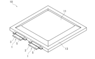
- FIG. 3 is a perspective view showing an example of a nonaqueous electrolyte battery including the lead wire for a nonaqueous electrolyte battery.
- FIG. 4 is a partial cross-sectional view schematically showing an embodiment of the non-aqueous electrolyte battery.
- the lead wire 1 for non-aqueous electrolyte batteries is the above-described lead wire for non-aqueous electrolyte batteries.
- the insulating film 5 has the first insulating layer 6, the second insulating layer 7 and the third insulating layer 8, as described above.
- the non-aqueous electrolyte battery 10 has a substantially square enclosure 11 and two non-aqueous electrolyte battery lead wires 1 extending from the inside of the enclosure 11 to the outside.
- the conductor 3 and the enclosing container 11 are connected via the insulating film 5 at the sealing portion 13 of the enclosing container 11 .
- the enclosed container 11 is a container that accommodates a positive electrode, a negative electrode, a separator, and a non-aqueous electrolyte in a sealed state.
- a positive electrode and a negative electrode are laminated via a separator to form a laminated electrode group.
- the laminated electrode group and the non-aqueous electrolyte are housed in an enclosed container 11 in a sealed state.
- the laminated electrode group is immersed in the electrolytic solution.
- the enclosed container 11 is formed from a sheet body as will be described later.
- the sealing portion 13 around the two sheets or one folded sheet is heat-sealed to provide a sealed state.
- one end 4 a of the conductor 3 of the lead wire 1 for non-aqueous electrolyte batteries is exposed from the enclosure 11 , and the other end 4 b is inside the enclosure 11 . It is arranged so as to be connected to the positive electrode.
- the other lead wire 1 for non-aqueous electrolyte batteries is arranged such that one end 4 a of the conductor 3 is exposed from the enclosure 11 and the other end 4 b is connected to the negative electrode in the enclosure 11 .
- the separator is usually an insulating and porous film. This separator is impregnated with a non-aqueous electrolyte.
- the other end portion 4b of the conductor 3 of the lead wire 1 for the negative electrode side of the non-aqueous electrolyte battery is connected to the internal connection lead wire 14 through the solder portion 15, and the internal connection lead wire 14 , is connected to a negative electrode (not shown).
- the intermediate portions of the lead wires 1 for a non-aqueous electrolyte battery are sandwiched by the sheet body, which is the enclosure 11, with an insulating film 5 interposed therebetween.
- the resin layer 27 and the outermost third insulating layer of the insulating film 5 of the plurality of lead wires 1 for a non-aqueous electrolyte battery are heat-sealed.
- the metal layer 25 has functions such as improving the strength of the enclosure 11 and preventing water vapor, oxygen, light, etc. from entering the battery.
- the metal layer 25 is made of metal such as aluminum foil.
- the metal layer 25 is mainly composed of metal. Examples of this metal include aluminum, copper, stainless steel, and titanium, with aluminum being particularly preferred.
- the metal layer 25 is substantially made of metal, but may contain additives other than metal.
- the metal layer 25 is in the form of a film, preferably made of metal foil, more preferably made of aluminum alloy foil. Also, the average thickness of the metal layer 25 is preferably about 10 ⁇ m to 50 ⁇ m.
- one end of the lead wire 1 for non-aqueous electrolyte battery that is, one end 4a of the conductor 3 is arranged in a state of being exposed from the enclosure 11, and is sealed by the enclosure 11. It is Specifically, lead wire 1 for non-aqueous electrolyte battery is arranged such that the innermost resin layer of enclosure 11 and insulating film 5 of lead wire 1 for non-aqueous electrolyte battery are in direct contact with each other.
- a method for manufacturing a non-aqueous electrolyte battery according to an embodiment of the present disclosure can be appropriately selected from known methods.
- the method for manufacturing the non-aqueous electrolyte battery includes, for example, a step of preparing a lead wire for the non-aqueous electrolyte battery, a step of preparing a laminated electrode group, a step of preparing a non-aqueous electrolyte, and a step of preparing the non-aqueous electrolyte battery A step of housing the laminated electrode group to which the lead wires are connected and the non-aqueous electrolyte in an enclosure.
- the adhesion between the conductor and the insulating film is excellent at high temperatures.
- Random polypropylene "Prime Polypro F227D” manufactured by Prime Polypro (PP4) Random polypropylene: “SunAllomer PF621S” manufactured by SunAllomer (PP5) Homopolypropylene: “SA3A” manufactured by Japan Polypro Co., Ltd. (PP6) Acid-modified random polypropylene: "Admer QF580” manufactured by Mitsui Chemicals, Inc. (PP7) Random polypropylene: “SunAllomer PF724S” manufactured by SunAllomer (PP8) Homopolypropylene: “MA3H” manufactured by Japan Polypro Co., Ltd. (PP9) Acid-modified homopolypropylene: "Admer QF500” manufactured by Mitsui Chemicals, Inc.
- the two insulating layer resin compositions were respectively charged and co-extruded to obtain a two-layer insulating film laminated in the order of the first insulating layer resin composition/second insulating layer resin composition.
- Table 1 shows the average thickness of each insulating layer.
- the obtained two-layer insulating film was cut into a predetermined size, and heat-sealed on both sides of the conductor under conditions of a mold temperature of 220° C. and a surface pressure of 0.3 MPa. And no. 3 to No. No. 7 lead wires for non-aqueous electrolyte batteries were obtained.
- the insulation layer resin composition is put into a third extruder, and the third insulation layer resin composition is put into a third extruder and co-extruded to form a first insulation layer resin composition/second insulation layer resin composition/third insulation layer resin composition.
- a three-layer insulating film was obtained which was laminated in the order of the layer resin composition. Table 1 shows the average thickness of each insulating layer. Next, the obtained three-layer insulating film was cut into a predetermined size, and heat-sealed on both sides of the conductor under conditions of a mold temperature of 220° C. and a surface pressure of 0.3 MPa. And no. 8 to No. Thirteen lead wires for non-aqueous electrolyte batteries were obtained.
- the sum of the products of the average thickness T in each insulating layer of the insulating film and the elastic modulus ED at the temperature D in the temperature range of 70 ° C. or higher and 130 ° C. or lower ⁇ (T ⁇ ED ) is 0.6 mm ⁇ MPa or more.
- No. 3, No. 4 and no. 6 to No. No. 13 had good peel strength at 130°C.
- the No. 1 insulating layer has a total sum ⁇ (T ⁇ E D ) of the product of the average thickness T and the elastic modulus E D of 5.0 mm ⁇ MPa or more. 6, No. 7 and no. 11 to No. No. 13 was particularly excellent in peel strength at 130°C.
- Nonaqueous Electrolyte Battery Lead Wire 3 Conductor 4a One End 4b Other End 5 Insulating Film 6 First Insulating Layer 7 Second Insulating Layer 8 Third Insulating Layer 10 Nonaqueous Electrolyte Battery 11 Enclosed Container 13 Sealing Part 14 For Internal Connection Lead wire 15 Solder part 25 Metal layer 26 Outermost resin layer 27 Innermost resin layer
Landscapes
- Chemical & Material Sciences (AREA)
- Chemical Kinetics & Catalysis (AREA)
- Electrochemistry (AREA)
- General Chemical & Material Sciences (AREA)
- Inorganic Chemistry (AREA)
- Laminated Bodies (AREA)
- Connection Of Batteries Or Terminals (AREA)
- Sealing Battery Cases Or Jackets (AREA)
Priority Applications (6)
| Application Number | Priority Date | Filing Date | Title |
|---|---|---|---|
| PCT/JP2021/048001 WO2023119586A1 (ja) | 2021-12-23 | 2021-12-23 | 非水電解質電池用リード線、絶縁膜及び非水電解質電池 |
| KR1020247020535A KR20240129165A (ko) | 2021-12-23 | 2022-08-12 | 비수 전해질 전지용 리드선, 절연막 및 비수 전해질 전지 |
| US18/721,797 US20250062515A1 (en) | 2021-12-23 | 2022-08-12 | Lead wire for nonaqueous electrolyte battery, insulating film, and nonaqueous electrolyte battery |
| PCT/JP2022/030817 WO2023119721A1 (ja) | 2021-12-23 | 2022-08-12 | 非水電解質電池用リード線、絶縁膜及び非水電解質電池 |
| CN202280085307.9A CN118541859A (zh) | 2021-12-23 | 2022-08-12 | 非水电解质电池用引线、绝缘膜以及非水电解质电池 |
| JP2023569052A JPWO2023119721A1 (https=) | 2021-12-23 | 2022-08-12 |
Applications Claiming Priority (1)
| Application Number | Priority Date | Filing Date | Title |
|---|---|---|---|
| PCT/JP2021/048001 WO2023119586A1 (ja) | 2021-12-23 | 2021-12-23 | 非水電解質電池用リード線、絶縁膜及び非水電解質電池 |
Publications (1)
| Publication Number | Publication Date |
|---|---|
| WO2023119586A1 true WO2023119586A1 (ja) | 2023-06-29 |
Family
ID=86901798
Family Applications (2)
| Application Number | Title | Priority Date | Filing Date |
|---|---|---|---|
| PCT/JP2021/048001 Ceased WO2023119586A1 (ja) | 2021-12-23 | 2021-12-23 | 非水電解質電池用リード線、絶縁膜及び非水電解質電池 |
| PCT/JP2022/030817 Ceased WO2023119721A1 (ja) | 2021-12-23 | 2022-08-12 | 非水電解質電池用リード線、絶縁膜及び非水電解質電池 |
Family Applications After (1)
| Application Number | Title | Priority Date | Filing Date |
|---|---|---|---|
| PCT/JP2022/030817 Ceased WO2023119721A1 (ja) | 2021-12-23 | 2022-08-12 | 非水電解質電池用リード線、絶縁膜及び非水電解質電池 |
Country Status (5)
| Country | Link |
|---|---|
| US (1) | US20250062515A1 (https=) |
| JP (1) | JPWO2023119721A1 (https=) |
| KR (1) | KR20240129165A (https=) |
| CN (1) | CN118541859A (https=) |
| WO (2) | WO2023119586A1 (https=) |
Citations (3)
| Publication number | Priority date | Publication date | Assignee | Title |
|---|---|---|---|---|
| JP2016091939A (ja) * | 2014-11-10 | 2016-05-23 | 凸版印刷株式会社 | 端子用樹脂フィルム、それを用いたタブ及び蓄電デバイス |
| JP2018014272A (ja) * | 2016-07-21 | 2018-01-25 | 住友電気工業株式会社 | 電気部品用リード線及び電気部品 |
| JP2020123591A (ja) * | 2018-08-30 | 2020-08-13 | 藤森工業株式会社 | 非水系電池用の電極リード線部材 |
Family Cites Families (10)
| Publication number | Priority date | Publication date | Assignee | Title |
|---|---|---|---|---|
| JP2002151024A (ja) * | 2000-11-15 | 2002-05-24 | Asahi Kasei Corp | 扁平型電池 |
| JP4635415B2 (ja) * | 2003-07-15 | 2011-02-23 | 凸版印刷株式会社 | 電極タブ用シーリング材 |
| JP4784236B2 (ja) | 2004-09-30 | 2011-10-05 | 住友電気工業株式会社 | 非水電解質電池用リード線及び非水電解質電池 |
| JP6349986B2 (ja) * | 2014-06-09 | 2018-07-04 | 凸版印刷株式会社 | 蓄電デバイス用端子フィルム及び蓄電デバイス |
| JP6706014B2 (ja) * | 2018-06-20 | 2020-06-03 | 大日本印刷株式会社 | 金属端子用接着性フィルム、接着性フィルム付き金属端子、及び電池 |
| KR20220034036A (ko) * | 2019-07-10 | 2022-03-17 | 다이니폰 인사츠 가부시키가이샤 | 금속단자용 접착성 필름, 금속단자용 접착성 필름 부착 금속단자, 상기 금속단자용 접착성 필름을 사용한 축전 디바이스, 및 축전 디바이스의 제조 방법 |
| WO2021090950A1 (ja) * | 2019-11-08 | 2021-05-14 | 大日本印刷株式会社 | 金属端子用接着性フィルム、金属端子用接着性フィルムの製造方法、金属端子用接着性フィルム付き金属端子、当該金属端子用接着性フィルムを用いた蓄電デバイス、及び蓄電デバイスの製造方法 |
| JP7566246B2 (ja) * | 2020-01-31 | 2024-10-15 | 住友電気工業株式会社 | 電池用タブリード |
| JP7676754B2 (ja) * | 2020-11-13 | 2025-05-15 | Toppanホールディングス株式会社 | 端子用樹脂フィルム、及びそれを用いた蓄電デバイス |
| JP7767736B2 (ja) * | 2021-05-28 | 2025-11-12 | Toppanホールディングス株式会社 | 端子用樹脂フィルム、及びそれを用いた蓄電デバイス |
-
2021
- 2021-12-23 WO PCT/JP2021/048001 patent/WO2023119586A1/ja not_active Ceased
-
2022
- 2022-08-12 CN CN202280085307.9A patent/CN118541859A/zh active Pending
- 2022-08-12 KR KR1020247020535A patent/KR20240129165A/ko active Pending
- 2022-08-12 JP JP2023569052A patent/JPWO2023119721A1/ja active Pending
- 2022-08-12 US US18/721,797 patent/US20250062515A1/en active Pending
- 2022-08-12 WO PCT/JP2022/030817 patent/WO2023119721A1/ja not_active Ceased
Patent Citations (3)
| Publication number | Priority date | Publication date | Assignee | Title |
|---|---|---|---|---|
| JP2016091939A (ja) * | 2014-11-10 | 2016-05-23 | 凸版印刷株式会社 | 端子用樹脂フィルム、それを用いたタブ及び蓄電デバイス |
| JP2018014272A (ja) * | 2016-07-21 | 2018-01-25 | 住友電気工業株式会社 | 電気部品用リード線及び電気部品 |
| JP2020123591A (ja) * | 2018-08-30 | 2020-08-13 | 藤森工業株式会社 | 非水系電池用の電極リード線部材 |
Also Published As
| Publication number | Publication date |
|---|---|
| CN118541859A (zh) | 2024-08-23 |
| JPWO2023119721A1 (https=) | 2023-06-29 |
| KR20240129165A (ko) | 2024-08-27 |
| US20250062515A1 (en) | 2025-02-20 |
| WO2023119721A1 (ja) | 2023-06-29 |
Similar Documents
| Publication | Publication Date | Title |
|---|---|---|
| JP7768068B2 (ja) | 非水電解質電池用リード線、絶縁膜及び非水電解質電池 | |
| US10347877B2 (en) | Battery packaging material | |
| CN103094497B (zh) | 电池用外包装体、电池用外包装体的制造方法和锂二次电池 | |
| JP7066227B2 (ja) | 封止フィルム並びにそれを用いたタブリード及び二次電池 | |
| JP6881320B2 (ja) | 非水電解質電池用リード線及びそれを含む非水電解質電池 | |
| WO2021246177A1 (ja) | 封止フィルム並びにそれを用いたタブリード及び二次電池 | |
| JP5375013B2 (ja) | 電気部品、非水電解質電池、並びに、それらに用いられるリード線及び封入容器 | |
| US20240178532A1 (en) | Tab sealants and power storage devices using the same | |
| KR102227239B1 (ko) | 비수 전해질 전지용 리드선 및 그것을 구비하는 비수 전해질 전지 | |
| JP7768067B2 (ja) | 非水電解質電池用リード線、絶縁膜及び非水電解質電池 | |
| WO2023119721A1 (ja) | 非水電解質電池用リード線、絶縁膜及び非水電解質電池 | |
| US20240186662A1 (en) | Lead wire for nonaqueous electrolyte battery, insulating film and nonaqueous electrolyte battery | |
| WO2023153301A1 (ja) | 非水電解質電池用リード線、絶縁膜及び非水電解質電池 | |
| JP2009110779A (ja) | 電気部品、非水電解質電池、並びに、それらに用いられるリード線及び封入容器 | |
| TW202446595A (zh) | 熱熔接著膜、密封膜、金屬端子、電池及裝置 | |
| JP2024030096A (ja) | タブリード封止用フィルム |
Legal Events
| Date | Code | Title | Description |
|---|---|---|---|
| 121 | Ep: the epo has been informed by wipo that ep was designated in this application |
Ref document number: 21969021 Country of ref document: EP Kind code of ref document: A1 |
|
| NENP | Non-entry into the national phase |
Ref country code: DE |
|
| 122 | Ep: pct application non-entry in european phase |
Ref document number: 21969021 Country of ref document: EP Kind code of ref document: A1 |
|
| NENP | Non-entry into the national phase |
Ref country code: JP |