WO2023119558A1 - 塗布装置 - Google Patents
塗布装置 Download PDFInfo
- Publication number
- WO2023119558A1 WO2023119558A1 PCT/JP2021/047878 JP2021047878W WO2023119558A1 WO 2023119558 A1 WO2023119558 A1 WO 2023119558A1 JP 2021047878 W JP2021047878 W JP 2021047878W WO 2023119558 A1 WO2023119558 A1 WO 2023119558A1
- Authority
- WO
- WIPO (PCT)
- Prior art keywords
- filter member
- main body
- powder
- plate
- opening
- Prior art date
Links
- 239000011248 coating agent Substances 0.000 title claims abstract description 114
- 238000000576 coating method Methods 0.000 title claims abstract description 114
- 239000000843 powder Substances 0.000 claims abstract description 255
- 230000002265 prevention Effects 0.000 claims description 19
- 239000000696 magnetic material Substances 0.000 claims description 8
- 230000004308 accommodation Effects 0.000 abstract description 5
- OYPRJOBELJOOCE-UHFFFAOYSA-N Calcium Chemical compound [Ca] OYPRJOBELJOOCE-UHFFFAOYSA-N 0.000 description 136
- 229910052791 calcium Inorganic materials 0.000 description 136
- 239000011575 calcium Substances 0.000 description 136
- 241000238814 Orthoptera Species 0.000 description 112
- 238000005192 partition Methods 0.000 description 27
- 238000003860 storage Methods 0.000 description 24
- 239000000853 adhesive Substances 0.000 description 19
- 230000001070 adhesive effect Effects 0.000 description 19
- 230000004048 modification Effects 0.000 description 19
- 238000012986 modification Methods 0.000 description 19
- 238000000926 separation method Methods 0.000 description 10
- XEEYBQQBJWHFJM-UHFFFAOYSA-N Iron Chemical compound [Fe] XEEYBQQBJWHFJM-UHFFFAOYSA-N 0.000 description 8
- 239000011347 resin Substances 0.000 description 7
- 229920005989 resin Polymers 0.000 description 7
- NIXOWILDQLNWCW-UHFFFAOYSA-N acrylic acid group Chemical group C(C=C)(=O)O NIXOWILDQLNWCW-UHFFFAOYSA-N 0.000 description 6
- 230000001105 regulatory effect Effects 0.000 description 5
- 241000938605 Crocodylia Species 0.000 description 4
- 229910052742 iron Inorganic materials 0.000 description 4
- 229910052751 metal Inorganic materials 0.000 description 4
- 239000002184 metal Substances 0.000 description 4
- 241001122767 Theaceae Species 0.000 description 3
- 230000009191 jumping Effects 0.000 description 3
- 239000000463 material Substances 0.000 description 3
- 230000006866 deterioration Effects 0.000 description 2
- 230000000694 effects Effects 0.000 description 2
- JVTAAEKCZFNVCJ-UHFFFAOYSA-N lactic acid Chemical compound CC(O)C(O)=O JVTAAEKCZFNVCJ-UHFFFAOYSA-N 0.000 description 2
- 238000004519 manufacturing process Methods 0.000 description 2
- 241000254032 Acrididae Species 0.000 description 1
- 241000894006 Bacteria Species 0.000 description 1
- 241001674044 Blattodea Species 0.000 description 1
- 241000238631 Hexapoda Species 0.000 description 1
- -1 acryl Chemical group 0.000 description 1
- 239000000428 dust Substances 0.000 description 1
- 238000010410 dusting Methods 0.000 description 1
- 235000014655 lactic acid Nutrition 0.000 description 1
- 239000004310 lactic acid Substances 0.000 description 1
- 238000000034 method Methods 0.000 description 1
- 235000015097 nutrients Nutrition 0.000 description 1
- 238000002360 preparation method Methods 0.000 description 1
- 230000000717 retained effect Effects 0.000 description 1
- 239000011435 rock Substances 0.000 description 1
- 238000003756 stirring Methods 0.000 description 1
- 235000013343 vitamin Nutrition 0.000 description 1
- 229940088594 vitamin Drugs 0.000 description 1
- 229930003231 vitamin Natural products 0.000 description 1
- 239000011782 vitamin Substances 0.000 description 1
- 150000003722 vitamin derivatives Chemical class 0.000 description 1
Images


Classifications
-
- B—PERFORMING OPERATIONS; TRANSPORTING
- B65—CONVEYING; PACKING; STORING; HANDLING THIN OR FILAMENTARY MATERIAL
- B65D—CONTAINERS FOR STORAGE OR TRANSPORT OF ARTICLES OR MATERIALS, e.g. BAGS, BARRELS, BOTTLES, BOXES, CANS, CARTONS, CRATES, DRUMS, JARS, TANKS, HOPPERS, FORWARDING CONTAINERS; ACCESSORIES, CLOSURES, OR FITTINGS THEREFOR; PACKAGING ELEMENTS; PACKAGES
- B65D25/00—Details of other kinds or types of rigid or semi-rigid containers
- B65D25/02—Internal fittings
- B65D25/04—Partitions
-
- B—PERFORMING OPERATIONS; TRANSPORTING
- B65—CONVEYING; PACKING; STORING; HANDLING THIN OR FILAMENTARY MATERIAL
- B65D—CONTAINERS FOR STORAGE OR TRANSPORT OF ARTICLES OR MATERIALS, e.g. BAGS, BARRELS, BOTTLES, BOXES, CANS, CARTONS, CRATES, DRUMS, JARS, TANKS, HOPPERS, FORWARDING CONTAINERS; ACCESSORIES, CLOSURES, OR FITTINGS THEREFOR; PACKAGING ELEMENTS; PACKAGES
- B65D77/00—Packages formed by enclosing articles or materials in preformed containers, e.g. boxes, cartons, sacks or bags
- B65D77/08—Materials, e.g. different materials, enclosed in separate compartments formed during filling of a single container
Definitions
- the present invention relates to a coating device.
- An object of the present invention is to provide an applicator capable of efficiently applying an appropriate amount of powder to an object to be applied.
- a coating device includes a first opening that opens upward in a vertical direction, and a second opening that opens in at least one of orthogonal directions orthogonal to the vertical direction at a lower end portion, a body portion capable of accommodating an object to be coated and powder; a first filter member closing the second opening of the body portion and through which the powder housed in the body portion can pass; and a powder containing portion for containing powder that has passed through the first filter member from the main body portion.
- the user puts the object to be coated and the powder from the opening of the main body.
- the object to be coated and the powder that have been put in are put on, for example, the bottom plate of the receiving part.
- the object to be coated and the powder are stirred on the upper side of the bottom plate, and the powder is applied to the object to be coated.
- the user tilts the upper side of the main body.
- the surplus powder applied to the article to be applied passes through the first filter member.
- the powder that has passed through the first filter member moves to the powder storage portion of the receiving portion. Therefore, the coating device can efficiently apply an appropriate amount of powder to the object to be coated.
- the main body includes a third opening that opens downward in the vertical direction, and is a member that is provided on the lower side of the main body and closes the third opening, through which the powder can pass. and a second filter member detachably provided at the lower end portion of the main body portion, and the powder applied to the object to be coated above the second filter member passes through the second filter member.
- the second filter member may be disposed at a coating position overlapping a bottom plate of the receiving portion in the up-down direction. A user puts the object to be coated and the powder from the second opening of the main body. The applied object and powder are placed on the upper side of the second filter member which is arranged so as to overlap the bottom plate of the receiving part.
- the object to be coated and the powder are stirred on the upper side of the second filter member, and the powder is applied to the object to be coated.
- the surplus powder applied to the object to be coated moves to the powder storage section via the first filter member.
- the surplus powder applied to the article to be applied passes through the second filter member.
- the powder that has passed through the second filter member falls onto the receiving portion. Therefore, the coating device can efficiently apply an appropriate amount of powder to the object to be coated.
- a first holding member that holds the second filter member in a state where the second filter member is superimposed on the bottom plate of the receiving portion at the application position; and a second holding member that holds the second filter member at a spaced position spaced apart from the bottom plate.
- the second filter member is held at the coating position and the separated position. The user applies the powder to the object to be coated at the application position of the second filter member, and moves the second filter member to the separation position. As a result, the surplus powder applied to the object to be coated passes through the second filter member and moves to the receiving portion. Therefore, the user can apply an appropriate amount of powder to the object to be coated simply by moving the powder from the application position to the separation position.
- the first holding member is made of a magnetic material
- one of the main body part and the receiving part includes a first magnetic material that emits a predetermined polarity
- the other of the main body part and the receiving part is:
- a second magnetic body that is attracted to the first magnetic body according to the predetermined polarity is provided, and the first magnetic body and the second magnetic body are opposed to each other and attract each other, so that the second filter member It may be held in an application position. Therefore, the coating device can hold the second filter member at the coating position with a simple configuration.
- the second holding member is made of a magnetic material
- the receiving part is provided above the second magnetic material, and includes a third magnetic material provided vertically aligned with the second magnetic material.
- the second filter member may be held at the spaced position by the first magnetic body and the third magnetic body facing each other and attracting each other. Therefore, the coating device can hold the second filter member at the separated position with a simple configuration.
- One of the body portion and the second filter member includes a fourth magnetic body having a predetermined polarity, and the other of the body portion and the second filter member has the predetermined polarity of the fourth magnetic body. and the second filter member is attached to the lower end of the main body by the fourth magnetic body and the fifth magnetic body facing and attracting each other. may be retained. Therefore, the coating device can attach and detach the second filter member to and from the main body with a simple configuration.
- first filter member and the second filter member may be an integral member. In this case, since it is not necessary to separately attach the first filter and the second filter to the main body, the manufacturing cost can be reduced.
- a movement prevention plate may be detachably provided inside the main body to prevent movement of the powder to the powder storage section.
- a lid may be provided to cover the first opening on the upper side of the main body.
- FIG. 11 is a side view showing the application position, the separation position, and the powder containing portion S of the filter member 116; It is a figure which shows the coating device 100C of a 3rd modification.
- FIG. 11 is a side view showing the application position of the filter member 116 and the powder containing portion S; It is a figure which shows coating device 100D of a 4th modification.
- FIG. 4 is a side view showing an application position and a separation position of the filter member 116; It is a figure which shows the coating device 100E of a 5th modification.
- a coating device 1A according to the first embodiment of the present invention will be described with reference to the drawings.
- the upper side, lower side, left side, right side, front side, and rear side of the coating apparatus 1A are respectively the upper side, the lower side, the upper left side, the lower right side, the lower left side, and the upper right side in FIG. handle.
- FIG. 1A A coating device 1A according to the first embodiment will be described with reference to FIGS. 1 and 2.
- FIG. The applicator 1A is used as live food for reptiles, for example, to apply calcium powder to crickets (not shown).
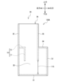
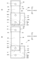
- the coating device 1A includes a main body portion 3, a filter member 115, a powder containing portion S, and the like.
- the main body 3 is made of transparent resin, such as plastic or acrylic.
- the main body 3 can accommodate crickets and calcium powder from above the opening 3A.
- the cricket and calcium powder stored in the main body 3 are placed on the bottom plate 3I.
- the main body 3 is formed in a rectangular parallelepiped shape extending vertically, including a front plate 3D, a rear plate 3F, a partition plate 3G, a left plate 3E, and a bottom plate 3I.
- the left plate 3E has a vertically long rectangular shape and extends upward from the left end of the bottom plate 3I.
- the front plate 3D extends upward from the front end of the bottom plate 3I.
- the front plate 3D forms an L shape in front view with the first rectangular portion 31D and the second rectangular portion 32D.
- the vertical length of the first rectangular portion 31D is equal to the vertical length of the left plate 3E.
- the second rectangular portion 32D has a rectangular shape elongated in the vertical direction, and extends to a substantially central portion of the first rectangular portion 31D in the vertical direction.
- the rear plate 3F extends upward from the rear end of the bottom plate 3I.
- the rear plate 3F is L-shaped and includes a first rectangular portion 31F and a second rectangular portion 32F.
- the second rectangular portion 32F has a vertically long rectangular shape, and extends to the substantially central portion of the first rectangular portion 31F in the vertical direction.
- the partition plate 3G is fixed to the right end portions of the first rectangular portions 31D and 31F. Thereby, an opening 3 ⁇ /b>A that opens upward is formed in the main body 3 .
- the shape of the opening 3A is a rectangular shape elongated in the horizontal direction in plan view.
- the partition plate 3G extends from the upper end to the lower end of the first rectangular portions 31D and 31F.
- the vertical length of the partition plate 3G is shorter than the length of the first rectangular portions 31D and 31F.
- a rectangular opening 24 opening to the right is formed at the lower end of the partition plate 3G.
- a filter member 115 is provided in the opening 24 .
- the filter member 115 has a rectangular shape extending in the front-rear direction. Four sides of the filter member 115 are fixed to the edge of the opening 24 with an adhesive or the like.
- the filter member 115 is impervious to crickets and permeable to calcium powder. Therefore, the base plate 3I, the first rectangular portions 31D and 31F, the partition plate 3G, and the filter member 115 form the main body portion 3. As shown in FIG.
- the right plate 3J has a vertically long rectangular shape and extends upward from the right end of the bottom plate 3I.
- the vertical length of the right plate 3J is equal to the length of the second rectangular portions 32D and 32F.
- the front end of the right plate 3J is connected to the right end of the second rectangular portion 32D, and the rear end of the right plate 3J is connected to the right end of the second rectangular portion 32F.
- An upper plate 3H is fixed to the upper ends of the second rectangular portions 32D and 32F and the upper end of the right plate 3J.
- the left end of the upper plate 3H is fixed to the right surface of the partition plate 3G.
- the powder containing portion S is formed on the right side of the filter member 115 by the bottom plate 3I, the partition plate 3G, the second rectangular portions 32D and 32F, the right plate 3J, and the top plate 3H.
- the powder containing portion S is a rectangular parallelepiped extending vertically.
- the powder containing portion S can contain calcium powder that has passed through the filter member 115 .
- the user tilts the upper end of the main body 3 to the right.
- the filter member 115 should be directed downward.
- the excess calcium powder applied to the cricket passes through the filter member 115 and moves to the powder containing portion S.
- the user takes out the cricket coated with calcium powder from the upper part of the opening 3A of the main body 3 .
- the user may turn the applicator 1A upside down and take out the cricket coated with calcium powder.
- calcium powder is stored in the right powder storage portion S. Therefore, the calcium powder does not fly out of the applicator 1A.
- the user may store the calcium powder with the coating apparatus 1A turned upside down. In this case, the powder contained in the powder containing portion S is less likely to come into direct contact with the outside air, so that it is protected from moisture. Therefore, the coating device 1A can suppress deterioration of the calcium powder when the calcium powder is stored.
- the user wants to apply calcium powder to another cricket after taking out the cricket, the user puts the cricket into the main body 3 again.
- the user moves the calcium powder accommodated in the powder accommodation portion S to the main body portion 3 by tilting the upper end side of the main body portion 3 to the left. Thereby, the user can use the calcium powder stored in the powder storage part S and apply it to the crickets.
- the main body 3 can accommodate cricket and calcium powder.
- the opening 3A of the main body 3 opens upward in the vertical direction.
- the opening 24 opens to the right in the left-right direction orthogonal to the up-down direction at the lower end.
- the filter member 115 closes the opening 24 of the main body 3 and allows the powder contained in the main body 3 to pass therethrough.
- the powder containing portion S is provided outside the body portion 3 and contains powder that has passed through the filter member 115 from the body portion 3 .
- the applicator 1A the user puts crickets and calcium powder through the opening 3A of the main body 3.
- the charged crickets and calcium powder are placed on the upper side of the bottom plate 3I.
- the crickets and calcium powder are stirred on the upper side of the bottom plate 3I when the user shakes the main body 3 or the like. This coats the crickets with calcium dust.
- excess calcium powder applied to the cricket passes through the filter member 115 .
- the calcium powder that has passed through the filter member 115 moves to the powder containing portion S. Therefore, the applicator 1A can efficiently apply an appropriate amount of calcium powder to the crickets. After that, the user takes out the cricket coated with calcium powder from the upper part of the opening 3A of the main body 3 .
- a coating device 100A according to the first modified example will be described with reference to FIG.
- the same reference numerals are given to the same members as those of the coating apparatus 1A of the above-described embodiment, and different reference numerals are given only to different portions.
- 100 A of coating devices of a 1st modification differ in the point provided with the main-body part 3K in addition to the structure of 1 A of coating devices. More specifically, the main body portion 3K is obtained by adding a regulating member 13 to the main body portion 3 of the coating apparatus 1A.
- the regulating member 13 is composed of a first regulating plate 15 and a second regulating plate 17 .
- the first regulation plate 15 is a rectangular plate elongated in the front-rear direction.
- the left end of the first regulation plate 15 is fixed to the central portion of the left plate 3E with an adhesive or the like.
- the front end of the first regulation plate 15 is fixed to the front plate 3D with an adhesive or the like.
- the rear end of the first regulation plate 15 is fixed to the rear plate 3F with an adhesive or the like.
- the second restricting plate 17 is a rectangular plate elongated in the vertical direction and extends downward from the right end of the first restricting plate 15 .
- the front end of the second regulation plate 17 is fixed to the front plate 3D with an adhesive or the like.
- the left end of the second regulation plate 17 is fixed to the rear plate 3F with an adhesive or the like.
- the first restricting plate 15 and the second restricting plate 17 may be integrally provided, or the restricting member 13 may be detachable from the main body portion 3 .
- the user places the cricket on the filter member 115 by tilting the main body 3K to the right. Thereby, the user moves the excess calcium powder adhering to the cricket to the powder container S. As shown in FIG. Therefore, the applicator 100A can apply an appropriate amount of calcium powder to the crickets. The user then removes the cricket.
- a coating device 100B according to a second modification will be described with reference to FIG.
- the same reference numerals are given to the same members as those of the coating apparatus 1A of the above-described embodiment, and different reference numerals are given only to different portions.
- the coating device 100B is different in that it includes a body portion 3Y instead of the body portion 3.
- FIG. More specifically, the body portion 3Y includes a powder storage portion S on the left side of the body portion 3 in addition to the powder storage portion S on the right side of the coating device 1A.
- the structure of the powder containing portion S on the left side is the same as the structure of the powder containing portion S on the right side. Therefore, the coating device 100B has a symmetrical shape.
- the main body 3Y is provided with a bottom plate 31I whose left side is larger than the bottom plate 3I of the coating apparatus 1A by the amount of the left powder containing portion S.
- the front plate 3D is provided with a second rectangular portion 32D on the left side in addition to the first rectangular portion 31D and the second rectangular portion 32D of the coating device 1A.
- the rear plate 3F the same applies to the rear plate 3F.
- the left powder storage section S may be provided on the front side or may be provided on the rear side. Further, even if the shape of the main body portion 3Y is not a rectangular parallelepiped but, for example, a cylindrical shape, the powder containing portion S may be provided as necessary.
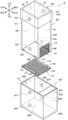
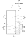
- the coating device 1B includes a body portion 30A, filter members 116 and 118, a receiving portion 60A, and a lid portion 200.
- the body portion 30A is made of a transparent resin, for example, a material such as plastic or acryl.
- the body portion 30A includes a front plate 30H, a rear plate 30I, a right plate 30J, and a left plate 30E, and is formed in a rectangular parallelepiped shape extending in the vertical direction.
- 30 A of main-body parts are formed with opening part 3A opened in the up-down direction.
- the shape of the opening 3A is a rectangular shape elongated in the horizontal direction in plan view.
- the body portion 30A can accommodate crickets and calcium powder from above the opening portion 3A.
- a magnet 301F is provided at the upper end of the front plate 30H and at the center in the left-right direction.
- a magnet 302F is provided at the lower end of the front plate 30H and the central portion in the left-right direction.
- the polarities of the magnets 301F and 302F are, for example, N poles.
- Magnets 303F and 304F are provided at the lower end of the front plate 30D.
- the magnet 303F is provided at the lower end and left end of the front plate 30H.
- the magnet 304F is provided at the lower end and right end of the front plate 30H.
- the magnets 303F and 304F are spaced apart by a predetermined distance in the horizontal direction.
- the polarities of the magnets 303F and 304F are, for example, N poles.
- a magnet 301R is provided at the upper end of the rear plate 30I and at the center in the left-right direction.
- a magnet 302R is provided at the lower end of the rear plate 30I and the central portion in the left-right direction.
- the polarities of the magnets 301R and 302R are, for example, N poles.
- Magnets 303R and 304R are provided at the lower end of the rear plate 30I of the main body 30A.
- the magnet 303R is provided at the lower end and left end of the rear plate 30I.
- the magnet 304R is provided at the lower end and right end of the rear plate 30I.
- the magnets 303R and 304R are spaced apart by a predetermined distance in the horizontal direction.
- the polarities of the magnets 303R and 304R are, for example, N poles.
- the right plate 30J has a rectangular opening 29 at its lower end.
- a filter member 118 is provided in the opening 29 of the right plate 30J.
- the filter member 118 has a rectangular shape extending in the front-rear direction. Four sides of the filter member 118 are fixed to the edge of the opening 29 of the right plate 30J with an adhesive or the like.
- the filter member 118 is impermeable to crickets and permeable to calcium powder.
- a filter member 116 is detachably attached to the lower end of the main body 30A.
- the filter member 116 includes a mesh portion 116A and fixing members 117F and 117R.
- the mesh portion 116A has a rectangular shape elongated in the left-right direction.
- the mesh portion 116A of the filter member 116 is configured to have a size that allows the passage of calcium powder and prevents the passage of live food such as crickets.
- the fixing members 117F and 117R are bar-shaped and extend in the left-right direction.
- the fixing members 117F and 117R are made of material such as acrylic or plastic, for example.
- the fixing member 117F is provided at the front end of the mesh portion 116A.
- the fixing member 117R is provided at the rear end portion of the mesh portion 116A.
- the fixing members 117F and 117R are fixed to the mesh portion 116A with an adhesive or the like, for example.
- Magnets 116L and 116R are provided on the fixed member 117F.
- the magnet 116L is provided at the left end of the fixed member 117F.
- the magnet 116R is provided at the right end of the fixed member 117F.
- the fixed member 117R is provided with magnets 116L and 116R.
- the magnet 116L is provided at the left end of the fixed member 117R.
- the magnet 116R is provided at the right end of the fixed member 117R.
- Magnet 116L and magnet 116R are spaced apart by a predetermined distance in the horizontal direction.
- the polarities of the magnets 116L and 116R are, for example, S poles.
- the magnets 116L and 116R of the front fixing member 117F face the magnets 303F and 304F of the front plate 30H, respectively.
- the magnets 116L, 116R of the rear fixed member 117R face the magnets 303R, 304R of the rear plate 30I of the main body 30A, respectively.
- the magnet 116L and the magnet 303F attract each other
- the magnet 116R and the magnet 304F attract each other in the front.
- the magnets 116L and 303R attract each other
- the magnets 116R and 304R attract each other. Therefore, the filter member 116 is positionally fixed to the lower end of the body portion 30A.
- the filter member 116 closes the opening 3A with a mesh portion 116A.
- the lid part 200 is made of transparent resin, for example, made of a material such as acrylic or plastic.
- the lid portion 200 has a substantially rectangular parallelepiped shape and includes an opening that opens downward.
- the shape of the opening is a rectangular shape elongated in the horizontal direction in plan view.
- Two magnets 201 are provided at the central portions of the front plate and the rear plate of the lid portion 200, respectively.
- the polarities of the two magnets 201 are, for example, S poles.
- the lid portion 200 can be attached to the upper end portion of the main body portion 30A.
- the lid portion 200 covers the opening portion 3A of the main body portion 30A from the upper side while being attached to the main body portion 30A.
- the two magnets 201 of the lid portion 200 and the magnets 301F and 301R of the body portion 30A face each other.
- the magnets 201 and 301F on the front side are attracted to each other, and the magnets 201 and 301R on the rear side are attracted to each other.
- the lid portion 200 is held with respect to the receiving portion 60A.
- the lid portion 200 may or may not be attached to the main body portion 30A.
- the receiving portion 60A is detachably provided at the lower end portion of the main body portion 30A.
- the receiving portion 60A covers the opening portion 3A of the main body portion 30A from below when attached to the main body portion 30A.
- the receiving portion 60A includes a front plate 600D, a rear plate 600F, a right plate 600G, a left plate 600E, a bottom plate 600H, and an upper plate 600I, and is formed in a rectangular parallelepiped shape extending in the left-right direction.
- the dimension of the receiving portion 60A in the left-right direction is longer than the length of the main body portion 30A in the left-right direction.
- the receiving portion 60A is made of a transparent resin, such as acrylic or plastic.
- Magnets 601F and 602F are provided on the front plate 600D of the receiving portion 60A.
- the magnet 601F is fixed to the upper end portion of the receiving portion 60A and the central portion in the left-right direction.
- the magnet 602F is fixed to the lower end of the front plate 600D and the central portion in the left-right direction.
- the magnets 601F and 602F of the front plate 600D are vertically spaced apart by a predetermined distance.
- the polarities of the magnets 601F and 602F are, for example, S poles.
- Magnets 601R and 602R are provided on the rear plate 600F of the receiving portion 60A.
- the magnet 601R is fixed to the upper end of the rear plate 600F and the central portion in the left-right direction.
- the magnet 602R is fixed to the lower end of the rear plate 600F and the central portion in the left-right direction.
- the magnets 601R and 602R of the rear plate 600F are vertically spaced apart by a predetermined distance.
- the polarities of the magnets 601R and 602R are, for example, S poles.
- the upper plate 600I has a rectangular shape extending in the front-rear direction, and is provided over the upper end of the right plate 600G, the upper right end of the front plate 600D, and the upper right end of the rear plate 600F. As a result, an opening 6A opening upward is formed in the receiving portion 60A.
- the application position of the filter member 116 will be described with reference to FIG. 6(A).
- the magnets 302F of the front plate 30H of the main body portion 30A face the magnets 602F of the front plate 600D of the receiving portion 60A.
- the magnets 302R of the rear plate 30I of the main body portion 30A face the magnets 602R of the rear plate 600F of the receiving portion 60A.
- the filter member 116 is arranged at a position vertically overlapping the bottom plate 600H of the receiving portion 60A. The position of the filter member 116 in this case is called an application position.
- the powder containing portion S is formed on the right side of the filter member 118, as in the coating device 1A.
- the separation position of the filter member 116 will be described with reference to FIG. 6(B).
- the lower end portion of the body portion 30A is moved upward by a predetermined distance from the state shown in FIG. It faces the magnet 601F of the plate 600D.
- the magnet 302R of the rear plate 30I of the main body portion 30A faces the magnet 601R of the rear plate 600F of the receiving portion 60A.
- the filter member 116 is arranged at a predetermined distance from the bottom plate 600H of the receiving portion 60A.
- the predetermined interval is, for example, 12 cm.
- the position of the filter member 116 in this case is called the separated position.
- the upper side of the body portion 30A should be tilted leftward.
- the coating device 1B since the filter member 116 and the bottom plate 600H are overlapped, the crickets and the calcium powder are agitated and the calcium powder is applied to the crickets.
- the user tilts the upper end of the main body 30A to the right.
- the filter member 118 should be directed downward.
- the excess calcium powder applied to the crickets passes through the filter member 118 and moves to the powder containing portion S.
- the user takes out the cricket coated with calcium powder from the upper portion of the opening 3A of the main body 30A.
- the user wants to apply calcium powder to another cricket after taking out the cricket, the user puts the cricket into the main body 30A again.
- the user can use the calcium powder stored in the powder storage part S and apply it to the crickets.
- the user may apply calcium powder to the cricket at the position shown in FIG. 6(A) and FIG. 6(B)). Even in this case, excess calcium powder applied to the cricket passes through the filter member 116 and moves to the receiving portion 60A.
- the main body 30A has the opening 3A that opens vertically and can accommodate crickets and calcium powder.
- the filter member 116 is provided on the lower side of the main body 30A and closes the opening 3A, and allows calcium powder to pass therethrough.
- the receiving portion 60A is detachably provided at the lower end portion of the main body portion 30A, and receives the calcium powder that has passed through the filter member 116 among the excess calcium powder applied to the crickets on the upper side of the filter member 116.
- the filter member 116 is arranged at a coating position overlapping the bottom plate 600H of the receiving portion 60A in the vertical direction.
- the user puts crickets and calcium powder through the opening 3A of the main body 30A.
- the crickets and calcium powder that have been thrown in are put on the upper side of the filter member 116 that is arranged to overlap with the bottom plate 600H of the receiving portion 60A.
- the crickets and calcium powder are agitated on the upper side of the filter member 116 by swinging the main body 30A by the user, and the calcium powder is applied to the crickets.
- the user tilts the main body 30A. In this case, the surplus powder applied to the object to be coated moves to the powder storage section S through the filter member 115 .
- the user separates the filter member 116 from the receiving portion 60A by, for example, moving the filter member 116 relatively upward together with the main body portion 30A with respect to the receiving portion 60A.
- excess calcium powder applied to the cricket passes through the filter member 116 .
- the calcium powder that has passed through the filter member 116 falls onto the receiving portion 60A. Therefore, the applicator 1B can efficiently apply an appropriate amount of calcium powder to the crickets. Thereafter, the user takes out the cricket coated with calcium powder from the upper portion of the opening 3A of the main body 30A.
- the magnets 302F, 302R, 602F, and 602R hold the position of the filter member 116 while the filter member 116 is superimposed on the bottom plate 60H of the receiving portion 60A at the coating position.
- Magnets 302F, 302R, 601F, and 601R hold filter member 116 at a spaced position where filter member 116 is spaced from bottom plate 60H of receiving portion 60A.
- the filter member 116 is held at the coating position and the separated position.
- the user moves the filter member 116 to the separation position while the calcium powder is applied to the crickets at the application position of the filter member 116 .
- excess calcium powder applied to the cricket passes through the filter member 116 and moves to the receiving portion 60A. Therefore, the user can apply an appropriate amount of calcium powder to the cricket simply by moving the cricket from the application position to the separation position.
- the body part 30A includes magnets 302F and 302R.
- the magnets 302F and 302R have north poles and are provided at the lower end of the main body 30A.
- the receiving portion 60A includes magnets 602F and 602R.
- the magnets 602F and 602R have south poles and are provided below the receiving portion 60A.
- the magnet 302F (302R) and the magnet 602F (602R) face and attract each other, thereby holding the filter member 116 at the application position. Therefore, the coating device 1B can hold the filter member 116 at the coating position with a simple configuration.
- the receiving portion 60A includes magnets 601F and 601R. Magnets 601F and 601R are provided above magnets 602F and 602R. That is, magnets 601F and 601R are aligned vertically with magnets 602F and 602R.
- the magnet 302F (302R) and the magnet 601F (601R) face each other and attract each other, so that the filter member 116 is held at the separated position. Therefore, the coating device 1B can hold the filter member 116 at the separated position with a simple configuration.
- the body part 30A includes magnets 303F, 304F (303R, 304R) having N poles.
- Filter member 116 includes magnets 116L, 116R (116L, 116R) having south poles. Filter member 116 is held at the lower end of main body 30A by magnets 303F, 304R (303R, 304R) and magnets 116L, 116R (116L, 116R) facing and attracting each other. Therefore, the coating device 1B can attach/detach the filter member 116 to/from the main body portion 30A with a simple configuration.
- the lid portion 200 covers the upper opening portion 3A of the main body portion 30A.
- the applicator 1B can more reliably reduce the calcium powder from jumping out of the main body 30A.
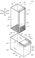
- a coating device 100C which is a modification of the second embodiment, will be described with reference to FIGS. 7 and 8.
- FIG. The same reference numerals are given to the same members as those of the coating device 1B of the above-described embodiment, and different reference numerals are given only to different portions.
- the coating device 100C is different in that a body portion 30B is provided instead of the body portion 30A of the coating device 1B, and a receiving portion 60B is provided instead of the receiving portion 60A of the coating device 1B.
- the main body part 30B includes a front plate 30D, a rear plate 30F, a left plate 30E, and a right plate 30J, and is formed in a rectangular parallelepiped shape extending in the vertical direction.
- the body portion 30B includes a movement prevention plate 330 and guide members 330F and 330R.
- the movement prevention plate 330 and the guide members 330F and 330R are made of transparent resin, such as plastic and acrylic.
- the movement prevention plate 330 has a rectangular shape extending in the vertical direction.
- a handle extending back and forth is provided at the upper end of the movement prevention plate 330 .
- the vertical length of the movement prevention plate 330 is substantially equal to the vertical length of the right plate 30J.
- the guide members 330F and 330R are bar-shaped and extend vertically.
- the guide member 330F is fixed to the inside and right end of the front plate 30D with an adhesive or the like.
- the guide member 330R is fixed to the inside and right end of the rear plate 30F with an adhesive or the like.
- the guide members 330F, 330R extend from the upper end of the main body portion 30B to the upper end of the filter member 118. As shown in FIG.
- the guide members 330F and 330R are fixed to the right plate 30J with a gap corresponding to the thickness of the movement prevention plate 330 in the left-right direction.
- the movement prevention plate 330 is inserted between the right plate 30J and the guide members 330F and 330R from above the body portion 30B.
- the lower end portion of the movement prevention plate 330 is arranged so as to overlap the filter member 118 in the left-right direction. Also, the lower end of the movement prevention plate 330 contacts the right end of the filter member 116 . Therefore, the calcium powder cannot move to the powder containing portion S through the filter member 118 .
- the movement prevention plate 330 may be insertable into the main body 30B from the front or rear, for example. Even in this case, the movement prevention plate 330 only needs to cover the filter member 118 .
- the receiving part 60B includes an upper plate 660 and guide members 660F, 660R, 661F and 661R instead of the upper plate 600I of the coating device 1B.
- the upper plate 660 and the guide members 660F, 660R, 661F, and 661R are made of transparent resin such as plastic and acrylic.
- the upper plate 660 is a plate extending in the front-rear direction.
- the upper plate 660 has substantially the same size as the upper plate 600I of the coating apparatus 1B.
- a handle is provided at the right end of the upper plate 660 .
- the guide members 660F, 660R, 661F, 661R are bar-shaped and extend in the left-right direction.
- the guide member 660F is fixed to the inner and upper right end of the front plate 600D with an adhesive or the like.
- the guide member 661F is fixed inside the front plate 600D and below the guide member 660F with an adhesive or the like.
- the guide members 660 ⁇ /b>F, 661 ⁇ /b>F are arranged vertically with a gap corresponding to the thickness of the upper plate 660 .
- the guide member 660R is fixed with an adhesive or the like to the inner and upper right end of the rear plate 600F.
- the guide member 661R is fixed inside the rear plate 600F and below the guide member 660R with an adhesive or the like.
- the guide members 660R and 661R are spaced apart by the thickness of the upper plate 660. As shown in FIG.
- the upper plate 660 is inserted between the guide member 660F and the guide member 661F and between the guide member 660R and the guide member 661R. With the upper plate 660 inserted, the upper plate 660 covers the upper right opening of the receiving portion 60B. As a result, an opening 6A opening upward is formed in the receiving portion 60B, similarly to the coating apparatus 1B.
- the user swings the body 30B back and forth, left and right, and up and down so that the cricket is coated with calcium powder.
- the movement prevention plate 330 prevents movement of the calcium powder to the powder container S. Therefore, the user can stir without worrying about the movement of the calcium powder to the powder container S.
- the user After the calcium powder is applied to the cricket, the user removes the movement prevention plate 330 from the main body 30B. Next, the user tilts the upper part of the body part 30A to the right as in the case of the coating device 1B. As a result, the excess calcium powder applied to the crickets passes through the filter member 118 and moves to the powder containing portion S. As shown in FIG. In this case, since the upper opening of the powder containing portion S is closed by the upper plate 660, the calcium powder will not jump out of the receiving portion 60B. Thereafter, the user takes out the cricket coated with calcium powder from the upper portion of the opening 3A of the main body 30B.
- the user After taking out the cricket, if the user wants to apply calcium powder to another cricket, the user puts the cricket into the main body 30B.
- the user removes the movement prevention plate 330 from the body portion 30B.
- the user can move the calcium powder remaining in the powder containing portion S to the main body portion 30B by tilting the upper end portion of the main body portion 30B to the left. After that, the movement prevention plate 330 is attached to the main body portion 30B.
- the user applies the calcium powder accommodated in the powder accommodation portion S to the cricket by shaking the main body portion 30B or the like.
- the user may move the main body portion 30B upward by a predetermined distance relative to the receiving portion 60B. Thereby, the user can apply calcium powder to the crickets as in the case of the application device 1B.
- the movement prevention plate 330 is detachably provided inside the main body portion 30B, and prevents the powder from moving to the powder containing portion S. As a result, when the calcium powder is applied to the crickets, the calcium powder does not move to the powder containing portion S. Therefore, the user can easily agitate the calcium powder against the crickets.
- the receiving portion 60B includes an upper plate 660.
- the upper plate 660 of the receiving portion 60B can prevent the calcium powder contained in the powder containing portion S from leaking to the outside.
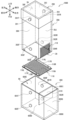
- a coating device 100D according to a fourth modification of the present invention will be described with reference to FIGS. 9 and 10.
- FIG. The same reference numerals are given to the same members as those of the coating device 1B of the above-described embodiment, and different reference numerals are given only to different portions.
- the coating device 100C is different in that a receiving portion 60C is provided instead of the receiving portion 60A of the coating device 1B.
- the receiving portion 60C includes a plate member 610 in addition to the configuration of the receiving portion 60A.
- the plate member 610 is provided inside the receiving portion 60C.
- the plate member 610 is a rectangular plate.
- the upper end of plate member 610 is connected to the left end of upper plate 600I.
- the front end of the plate member 610 is fixed inside and to the upper right of the front plate 600D.
- the rear end of the plate member 610 is fixed inside and to the upper right of the rear plate 600F. Accordingly, the plate member 610 extends vertically and forwardly inside the receiving portion 60C.
- the plate member 610 is arranged on the right side of the right plate 30J of the main body portion 30A. be. In this case, the left surface of plate member 610 contacts right plate 30J.
- the filter member 116 when the filter member 116 is arranged at the spaced position, the filter member 118 is arranged on the right side of the plate member 610 . As a result, the plate member 610 does not allow the calcium powder to move to the powder containing portion S through the 118 .
- the plate member 610 guides the main body 30A in the vertical direction when the receiving portion 60C is inserted into or removed from the main body 30A. Further, on the right side of the powder containing portion S of the receiving portion 60C, a storage portion composed of the plate member 610, the upper plate 600I, the right plate 600G, the right side of the front plate 600D, and the right side of the rear plate 600F is formed. be done.
- the storage section has a rectangular parallelepiped shape that opens downward.
- the user places the filter member 116 at the application position. As in the application device 100A, the user applies calcium powder to the crickets. In this case, the user moves the excess calcium powder applied to the crickets to the powder container S via the filter member 118 while the filter member 116 is placed at the application position. Further, the user moves the excess calcium powder applied to the crickets to the powder container S via the filter member 116 by moving the filter member 116 from the application position to the separation position. After that, the user takes out the cricket coated with calcium powder from the coating device 100D.
- the user may turn the coating device 100D upside down to take out the crickets.
- the excess calcium powder is stored in the storage section of the powder storage section S. Therefore, the applicator 100D can prevent the calcium powder from jumping out of the receiver 60C, as in the case of the applicator 1A.
- the user can store calcium powder in the same manner as in the case of the applicator 1A.
- the user stores the calcium powder in the storage section of the powder storage section S by turning the receiving section 60C upside down. Therefore, the coating device 100D can protect the calcium powder stored in the receiving part 60C from moisture.
- the receiving part 60C includes the plate member 610 in the coating device 100D.
- the coating device 100D can apply calcium powder in the same manner as the coating device 100A.
- the coating device 100D can prevent calcium powder from moving to the outside of the receiving part 60C, as in the case of the coating device 1A.
- the coating device 100D can suppress deterioration of the calcium powder due to moisture or the like, as in the case of the coating device 1A.
- a coating device 100E according to a fifth modification of the present invention will be described with reference to FIG.
- the same reference numerals are given to the same members as those of the coating apparatus 1A of the above-described embodiment, and different reference numerals are given only to different portions.
- the coating device 100E includes a body portion 3B instead of the body portion 3 of the coating device 1A.
- the main body portion 3B is provided with protruding portions 71F, 71R, 72F, and 72R and a partition plate 73.
- a filter member 115A is attached to the main body portion 3B instead of the filter member 115 of the coating device 1A.
- the protrusions 71F and 71R are provided at the lower end of the partition plate 3G.
- the protruding portions 71F and 71R are arranged with a predetermined space therebetween.
- the protrusions 71F and 71R protrude downward from the lower end of the partition plate 3G.
- the protrusions 72F and 72R are provided on the right side of the bottom plate 3I.
- the positions of the protrusions 72F and 72R are directly below the protrusions 71F and 71R.
- the protruding portions 72F and 72R are arranged with a predetermined space in the front-rear direction.
- the protrusions 72F and 72R protrude upward from the bottom plate 3I.
- the shape of the protruding portions 71F, 71R, 72F, and 72R may be rectangular parallelepiped or semicircular.
- the partition plate 74 is provided in the central portion of the filter member 115A in the vertical direction.
- the partition plate 74 has a rectangular shape extending in the front, rear, left, and right directions.
- the front end of the partition plate 74 is fixed to the second rectangular portion 32D of the front plate 3D with an adhesive or the like.
- the rear end of the partition plate 75 is fixed to the second rectangular portion 32F of the rear plate 3F with an adhesive or the like.
- the right end of the partition plate 74 is arranged near the center of the powder container S in the left-right direction.
- the partition plate 75 is provided at the right end of the partition plate 74 .
- the partition plate 75 extends upward from the right end of the partition plate 74 . That is, the partition plate 75 is a plate extending in the front-rear and up-down directions.
- the upper end of the partition plate 75 is separated from the upper plate 3H.
- the front end of the partition plate 75 is fixed to the second rectangular portion 32D of the front plate 3D with an adhesive or the like.
- the rear end of the partition plate 75 is fixed to the second rectangular portion 32F of the rear plate 3F with an adhesive or the like.
- the powder containing section S is divided by partition plates 74 and 75 .
- the powder container S can move the calcium powder in the direction indicated by the arrow A.
- the filter member 115A includes a frame 81.
- the frame 81 has a rectangular shape and substantially the same shape as the opening 29 .
- a mesh portion is fixed inside the frame 81 .
- the frame 81 of the filter member 115A is provided with recesses 77F, 77R, 78F, and 78R.
- the recessed portions 77F and 77R are provided at the upper end portion of the frame 81 of the filter member 115A.
- the recessed portions 77F and 77R are arranged with a predetermined space in the front-rear direction.
- the recessed portions 77F and 77R are recessed downward.
- the positions of the recesses 77F and 77R correspond to the positions of the projections 71F and 71R, respectively.
- the recesses 78F and 78R are provided at the lower end of the frame 81 of the filter member 115A.
- the recessed portions 78F and 78R are recessed upward.
- the positions of the recesses 78F and 78R correspond to the positions of the protrusions 72F and 72R, respectively.
- the shapes of the recesses 77F, 77R, 78F and 78R correspond to the shapes of the projections 71F, 71R, 72F and 72R.
- the recessed portions 77F, 77R, 78F, and 78R are recessed in a rectangular parallelepiped shape or a semicircular shape.
- a handle portion 70 is provided on the filter member 115A.
- the handle portion 70 is fixed to the upper end portion of the filter member 115A over the front and rear.
- the handle portion 70 extends leftward from the upper end portion of the filter member 115A.
- protrusions 71F, 71F, 72F, and 72R is not limited.
- one or three or more projecting portions may be provided on the upper side of the frame 81 , or one or three or more projecting portions may be provided on the lower side of the frame 81 .
- the number and arrangement of the recesses may be determined accordingly.
- the user engages the depressions 78F, 78R of the filter member 115A with the protrusions 72F, 72R.
- the user rotates the filter member 115A around the recessed portions 78F and 78R while holding the handle portion 70.
- the user engages the concave portions 77F and 77R of the filter member 115A with the projecting portions 71F and 72F.
- the upper end of the frame 81 may be provided with lateral grooves to guide the recesses 77F and 77R with respect to the protrusions 71F and 71F.
- the user can apply calcium powder to the crickets, similar to the application device 1A of the first embodiment. Further, the user may move the surplus powder among the calcium powder applied to the cricket to the powder storage section S via the filter member 115A.
- the user may store the calcium powder in the powder storage section S as in the first embodiment. For example, when the calcium powder is moved to the powder containing portion S, the user may keep the calcium powder in the powder containing portion S as it is. Thereafter, when applying calcium powder to new crickets, the user moves the powder stored in the powder storage portion S to the left side of the bottom plate 3I via the lower side of the central portion of the filter member 115A. The user then applies calcium powder to the crickets.
- the user shakes the main body 3B to move the calcium powder stored in the powder container S along the path of arrow A shown in FIG.
- the user moves the calcium powder, which has been moved to the right side of the bottom plate 3I, from the powder container S to the left side of the bottom plate 3I via the portion above the central portion of the filter member 115A.
- the user then applies calcium powder to the crickets.
- the partition plate 3G of the main body portion 3B includes the projecting portions 71F and 71R. Further, the bottom plate 3I of the main body portion 3B is provided with projecting portions 72F and 72R.
- the filter member 115A includes recessed portions 77F, 77R, 78F and 78R. As a result, the filter member 115A can be attached to and detached from the opening 29 of the main body 3. As shown in FIG.
- a handle portion 70 is provided on the filter member 115A. This improves the operability of the filter member 115A when the user attaches and detaches the filter member 115A.
- Partition plates 74 and 75 are provided in the powder storage section S. Thereby, the user can apply the powder in the powder containing portion S to the crickets from the portion above the central portion of the filter member 115A.
- crickets are used as live baits for reptiles in the coating devices 1A and 1B of the above embodiments
- other insects such as cockroaches and grasshoppers may be used as baits.
- calcium powder is applied, but the present invention is not limited to this, and powders such as vitamin preparations containing other nutrients and lactic acid bacteria may be used.
- the shapes of the coating devices 1A and 1B may be changed as appropriate.
- the coating apparatuses 1A and 1B may have a substantially rectangular parallelepiped shape, they may have a cylindrical shape or a triangular prism shape.
- the coating devices 1A and 1B are made of transparent resin, they may be translucent or colored. It is even better if the user can see the inside.
- the coating device 1A is not provided with the lid portion 200 of the coating device 1B, the lid portion 200 may be attached.
- the main body 3 preferably has a magnet that attracts the magnet 201 of the lid 200 .
- the powder containing portion S is formed in the coating device 1A, the shape of the powder containing portion S may be changed as appropriate. Moreover, the powder containing portion S may be detachable from the main body portion 3 .
- the filter member 115 is provided in the coating device 1A, the filter member 118 of the coating device 1B may be provided. Although the filter member 115 is fixed to the body portion 3 , it may be detachable from the body portion 3 . In this case, the filter member 115 may have meshes of different sizes according to the size of the cricket. The shape of the filter member 118 may be changed as appropriate.
- the shapes of the lid portion 200 and the receiving portion 60A may be changed as appropriate.
- the lid portion 200 and the receiving portion 60A may have the same shape.
- one member having the same shape can be used both as the lid portion 200 and the receiving portion 60A.
- the lid portion 200 may be attachable to the lower end portion of the main body portion 30A. In this case, the lid portion 200 can cover the opening portion 3A from below while being attached to the lower end portion side of the main body portion 30A.
- the lid portion 200 may be detachable from the main body portion 30A.
- the filter member 116 may be moved to the separation position after the calcium powder is applied to the crickets while the filter member 116 is placed at the application position. Even in this case, excess calcium powder adhering to the cricket moves below the filter member 116 .
- the receiving portion 60A may be detachable from the upper end portion of the main body portion 30A.
- the receiving portion 60A can cover the opening portion 3A from above while being attached to the upper end portion of the main body portion 30A.
- the user removes the receiving portion 60A and attaches the lid portion 200 to the lower end portion of the main body portion 30A.
- the calcium powder accumulated in the receiving portion 60A can be put into the main body portion 30A again. The user can then attach the receiving portion 60A to the upper end of the body portion 30A.
- the magnets 301F and 302F and the magnets 301R and 302 of the main body 30A are vertically spaced apart by a predetermined distance, but the predetermined distance may be changed as appropriate.
- the magnets 601F, 601R, 601R, and 602R of the receiving portion 60A are preferably arranged corresponding to the changed spacing.
- the distance is not limited to this, and the predetermined distance may be changed as appropriate.
- the intervals between the magnets 116L and 116R provided on the fixing members 117F and 117R of the filter member 116 may also be appropriately changed.
- the magnets 602F and 602R are provided in the receiving portion 60A, they are not limited to this.
- the magnets 602F, 602R may be omitted.
- the magnets 302F, 302R, 601F, and 601R can hold the filter member 116 at the application position and the separated position.
- Magnets 301F, 301R, 302F, 302R may not be provided.
- a metal such as iron may be provided that emits a magnetic force of predetermined polarity upon proximity to the magnets 601F, 601R.
- the magnets 601F, 601R may not be provided.
- a metal such as iron may be provided that emits a magnetic force of predetermined polarity upon proximity to the magnets 302F, 302R.
- the filter member 116 is detachable from the lower end portion of the main body portion 30A, it is not limited to this, and the filter member 116 may be non-detachably fixed.
- mesh portion 116A of filter member 116 may be fixed to the lower end of body portion 30A with an adhesive, and magnets 303F and 304F of body portion 30A may be omitted.
- the fixing members 117F and 117R of the filter member 116 may be omitted.
- the filter member 116 is held at the application position and the separated position by the magnets 302F, 302R and the magnets 601F, 601R, 602F, 602R, but is not limited to this.
- the magnets 301F, 301R, 302F, 302R may not be provided.
- a metal such as iron may be provided that emits a magnetic force of predetermined polarity when approaching the magnets 601F, 601R, 602F, 601R.
- the magnets 601F, 601R, 602F, 601R may not be provided.
- a metal such as iron may be provided that emits a magnetic force of predetermined polarity upon proximity to the magnets 301F, 301R, 302F, 302R.
- the filter member 116 may be held at the application position and the separated position by, for example, a latch mechanism or the like. It should be noted that it is not necessary to provide a member for holding the application position and the separation position. At the separated position, the predetermined distance between the filter member 116 and the bottom plate 600H is 12 cm, but it is not limited to this and may be set as appropriate.
- filter member 118 is fixed to the right plate 30J in the coating device 1B, it is not limited to this.
- filter member 118 may be detachable from body portion 30A like filter member 116 .
- the filter member 118 may be replaceable with another filter member having a different mesh.
- the filter member 116 may be non-removably fixed.
- the filter member 116 and the filter member 118 are provided in the coating device 1B, the filter member 116 may not be provided.
- the main body portion 30A may be open at the lower end, or may be covered with a plate. In this case, the user can use the filter member 118 to apply an appropriate amount of calcium powder to the crickets.
- the filter member 118 may be omitted in the coating device 1B.
- the user can use the filter member 116 to apply an appropriate amount of calcium powder to the crickets.
- the filter member 116 and the filter member 118 are provided separately in the coating device 1B, they may be integrated. In this case, it is not necessary to separately attach the filter member 116 and the filter member 118 to the main body portion 30A, so the manufacturing cost can be reduced.
- the coating device 1B is provided with the receiving portion 60A, it is not limited to this.
- the receiving portion 60B may be detachable from the main body portion 30A. Even in this case, the calcium powder inside the receiving portion 60B does not jump out.
- the opening 3A is an example of the "first opening” of the present invention.
- the openings 24 and 29 are examples of the “second opening” of the present invention.
- a cricket is an example of the "object to be coated” of the present invention.
- Calcium powder is an example of the "powder” of the present invention.
- Filter members 115, 115A, and 118 are examples of the "first filter member” of the present invention.
- the opening 3A is an example of the "third opening” of the present invention.
- Filter member 116 is an example of the "second filter member” of the present invention.
- Magnets 302F, 302R, 602F, and 602R are examples of "first holding members.” Magnets 302F, 302R, 601F, and 601R are examples of “second holding members.” Magnets 302F and 302R are an example of the "first magnetic body” of the present invention. Magnets 602F and 602R are an example of the "second magnetic body” of the present invention. Magnets 601F and 601R are an example of the "third magnetic body” of the present invention. Magnets 303F, 304F, 303R, and 304R are examples of the "fourth magnetic body” of the present invention. Magnets 116L and 116R are an example of the "fifth magnetic body” of the present invention. The north pole is an example of the "predetermined polarity" of the present invention.
Landscapes
- Engineering & Computer Science (AREA)
- Mechanical Engineering (AREA)
- Coating Apparatus (AREA)
Priority Applications (2)
| Application Number | Priority Date | Filing Date | Title |
|---|---|---|---|
| PCT/JP2021/047878 WO2023119558A1 (ja) | 2021-12-23 | 2021-12-23 | 塗布装置 |
| JP2023568935A JPWO2023119558A1 (en, 2012) | 2021-12-23 | 2021-12-23 |
Applications Claiming Priority (1)
| Application Number | Priority Date | Filing Date | Title |
|---|---|---|---|
| PCT/JP2021/047878 WO2023119558A1 (ja) | 2021-12-23 | 2021-12-23 | 塗布装置 |
Publications (1)
| Publication Number | Publication Date |
|---|---|
| WO2023119558A1 true WO2023119558A1 (ja) | 2023-06-29 |
Family
ID=86901764
Family Applications (1)
| Application Number | Title | Priority Date | Filing Date |
|---|---|---|---|
| PCT/JP2021/047878 WO2023119558A1 (ja) | 2021-12-23 | 2021-12-23 | 塗布装置 |
Country Status (2)
| Country | Link |
|---|---|
| JP (1) | JPWO2023119558A1 (en, 2012) |
| WO (1) | WO2023119558A1 (en, 2012) |
Citations (6)
| Publication number | Priority date | Publication date | Assignee | Title |
|---|---|---|---|---|
| JPS58163482U (ja) * | 1982-04-24 | 1983-10-31 | 宮田 均 | 選別孔付茶筒 |
| JPS63132646U (en, 2012) * | 1987-02-21 | 1988-08-30 | ||
| JPH04266729A (ja) * | 1991-02-20 | 1992-09-22 | Shinkichi Matsushita | 篩付きの容器 |
| JPH07315455A (ja) * | 1994-05-23 | 1995-12-05 | Sumitomo Metal Mining Co Ltd | 粒子状物質用容器 |
| JP2014031176A (ja) * | 2012-08-01 | 2014-02-20 | Dainippon Printing Co Ltd | ブレンド機能を有する包装用袋 |
| JP2015221678A (ja) * | 2014-05-23 | 2015-12-10 | 千鶴 竹内 | 食品包装用袋 |
Family Cites Families (1)
| Publication number | Priority date | Publication date | Assignee | Title |
|---|---|---|---|---|
| KR102482404B1 (ko) * | 2017-08-30 | 2022-12-29 | 가부시키가이샤 코세 | 화장료 용기 |
-
2021
- 2021-12-23 WO PCT/JP2021/047878 patent/WO2023119558A1/ja active Application Filing
- 2021-12-23 JP JP2023568935A patent/JPWO2023119558A1/ja active Pending
Patent Citations (6)
| Publication number | Priority date | Publication date | Assignee | Title |
|---|---|---|---|---|
| JPS58163482U (ja) * | 1982-04-24 | 1983-10-31 | 宮田 均 | 選別孔付茶筒 |
| JPS63132646U (en, 2012) * | 1987-02-21 | 1988-08-30 | ||
| JPH04266729A (ja) * | 1991-02-20 | 1992-09-22 | Shinkichi Matsushita | 篩付きの容器 |
| JPH07315455A (ja) * | 1994-05-23 | 1995-12-05 | Sumitomo Metal Mining Co Ltd | 粒子状物質用容器 |
| JP2014031176A (ja) * | 2012-08-01 | 2014-02-20 | Dainippon Printing Co Ltd | ブレンド機能を有する包装用袋 |
| JP2015221678A (ja) * | 2014-05-23 | 2015-12-10 | 千鶴 竹内 | 食品包装用袋 |
Also Published As
| Publication number | Publication date |
|---|---|
| JPWO2023119558A1 (en, 2012) | 2023-06-29 |
Similar Documents
| Publication | Publication Date | Title |
|---|---|---|
| US5526927A (en) | Tackle box with magnetically attractive panes | |
| JP5661045B2 (ja) | 容器 | |
| US4739353A (en) | Packaged camera assembly | |
| US20140034080A1 (en) | Magnetic closure | |
| US3197915A (en) | Magnetic box for ferrous items | |
| RU2503598C2 (ru) | Контейнер с шарнирной крышкой | |
| WO2023119558A1 (ja) | 塗布装置 | |
| UA107885C2 (uk) | Пачка для тютюнових виробів, групова упаковка, що містить сукупність пачок, та заготовка для виготовлення пачок для тютюнових виробів | |
| JP2001315831A (ja) | 磁石式キャップと磁石蓋 | |
| JP4691235B2 (ja) | 収骨容器 | |
| US20220287275A1 (en) | Multi-Compartment Bag Useful for Walking a Dog | |
| JPH0733660Y2 (ja) | 防虫剤などの薬剤装置 | |
| JP2022103778A (ja) | 塗布装置 | |
| JP3148416U (ja) | 筆記具ケース | |
| US11751663B2 (en) | Magnetic cap assembly and a container using the same | |
| JPH0256672B2 (en, 2012) | ||
| JP3214437U (ja) | 粒状排泄物処理材の貯蔵補給装置 | |
| JP2006020589A (ja) | 携帯用餌箱 | |
| GB2299212A (en) | Magnetic holding devices | |
| CN208746635U (zh) | 一种多功能盒子 | |
| JP2023174273A (ja) | コンパクト容器 | |
| JP2012086973A (ja) | 空容器回収ボックス | |
| JP3260582B2 (ja) | 蓋付容器 | |
| JPS5827607Y2 (ja) | 移植機 | |
| JPS6331634Y2 (en, 2012) |
Legal Events
| Date | Code | Title | Description |
|---|---|---|---|
| 121 | Ep: the epo has been informed by wipo that ep was designated in this application |
Ref document number: 21968993 Country of ref document: EP Kind code of ref document: A1 |
|
| WWE | Wipo information: entry into national phase |
Ref document number: 2023568935 Country of ref document: JP |
|
| NENP | Non-entry into the national phase |
Ref country code: DE |
|
| 122 | Ep: pct application non-entry in european phase |
Ref document number: 21968993 Country of ref document: EP Kind code of ref document: A1 |