WO2023119480A1 - 超音波送受波器用のアタッチメント - Google Patents
超音波送受波器用のアタッチメント Download PDFInfo
- Publication number
- WO2023119480A1 WO2023119480A1 PCT/JP2021/047559 JP2021047559W WO2023119480A1 WO 2023119480 A1 WO2023119480 A1 WO 2023119480A1 JP 2021047559 W JP2021047559 W JP 2021047559W WO 2023119480 A1 WO2023119480 A1 WO 2023119480A1
- Authority
- WO
- WIPO (PCT)
- Prior art keywords
- ultrasonic transducer
- acoustic lens
- holding member
- attachment
- ultrasonic
- Prior art date
- Legal status (The legal status is an assumption and is not a legal conclusion. Google has not performed a legal analysis and makes no representation as to the accuracy of the status listed.)
- Ceased
Links
Images





Classifications
-
- G—PHYSICS
- G01—MEASURING; TESTING
- G01S—RADIO DIRECTION-FINDING; RADIO NAVIGATION; DETERMINING DISTANCE OR VELOCITY BY USE OF RADIO WAVES; LOCATING OR PRESENCE-DETECTING BY USE OF THE REFLECTION OR RERADIATION OF RADIO WAVES; ANALOGOUS ARRANGEMENTS USING OTHER WAVES
- G01S15/00—Systems using the reflection or reradiation of acoustic waves, e.g. sonar systems
- G01S15/88—Sonar systems specially adapted for specific applications
- G01S15/96—Sonar systems specially adapted for specific applications for locating fish
-
- G—PHYSICS
- G01—MEASURING; TESTING
- G01S—RADIO DIRECTION-FINDING; RADIO NAVIGATION; DETERMINING DISTANCE OR VELOCITY BY USE OF RADIO WAVES; LOCATING OR PRESENCE-DETECTING BY USE OF THE REFLECTION OR RERADIATION OF RADIO WAVES; ANALOGOUS ARRANGEMENTS USING OTHER WAVES
- G01S7/00—Details of systems according to groups G01S13/00, G01S15/00, G01S17/00
- G01S7/52—Details of systems according to groups G01S13/00, G01S15/00, G01S17/00 of systems according to group G01S15/00
- G01S7/521—Constructional features
Definitions
- the present invention relates to an attachment attached to an ultrasonic transducer.
- an ultrasonic transducer housing an ultrasonic transducer is suspended by a cable for signal transmission and immersed in water, and an ultrasonic transducer that detects a school of fish by transmitting and receiving ultrasonic waves from the ultrasonic transducer. It has been known.
- This ultrasonic transducer is used, for example, in ice fishing such as smelt fishing.
- the ultrasonic transmitter/receiver is inserted into the water through a hole made in the ice during ice fishing.
- Japanese Patent Application Laid-Open No. 59-85972 (Figs. 2, 5, 6, etc.) Japanese Patent Application Laid-Open No. 5-212355 (claim 2, paragraphs [0012], [0023], FIG. 1, FIG. 2, etc.) JP-A-10-179582 (paragraph [0017], FIG. 1, etc.) Japanese Patent Application Laid-Open No. 2001-169393 (claims 1, 3, 4, paragraphs [0010], [0016], FIG. 1, FIG. 4, etc.) Japanese Patent Application Laid-Open No. 9-298795 (claim 3, paragraphs [0035], [0037], FIGS. 6 to 8, etc.)
- the ultrasonic transducer in order to improve the detection accuracy of the ultrasonic transducer, it is preferable to irradiate (transmit) the ultrasonic wave vertically downward with the acoustic emission surface of the ultrasonic transducer horizontal.
- the acoustic radiation surface is kept horizontal by the weight of the transducer.
- the ultrasonic transmitter/receiver is tilted, the acoustic radiation surface is also tilted, so the direction of the irradiated ultrasonic waves is tilted with respect to the vertical direction. In this case, since the school of fish cannot be detected accurately, there is a problem that an error occurs in the display on the fish finder.
- the present invention has been made in view of the above problems, and the first object is that even if there is only one ultrasonic transmitter/receiver, it can be used by changing it to a different directional characteristic depending on the situation.
- a second object of the present invention is to provide an attachment for an ultrasonic transducer capable of transmitting ultrasonic waves vertically downward and improving detection accuracy by maintaining the ultrasonic transducer horizontally. be.
- the invention according to claim 1 is a fish finder in which an ultrasonic transducer that is suspended from a cable and transmits and receives ultrasonic waves is housed in a molded state, and whose bottom surface is an acoustic radiation surface.
- a holding member for detachably holding the ultrasonic transducer so that the acoustic radiation surface is acoustically connected to the flat surface of the acoustic lens;
- the gist thereof is an attachment for an ultrasonic transducer, characterized by comprising a leveling means for keeping an acoustic lens horizontal.
- the ultrasonic transducer is detachably held by the holding member, and the acoustic lens is arranged on the acoustic radiation surface side of the ultrasonic transducer held by the holding member. be. Therefore, even if there is only one ultrasonic transmitter/receiver, it is possible to change the directional characteristics of the ultrasonic waves emitted from the acoustic radiation surface to different directional characteristics depending on the situation. Specifically, by holding the ultrasonic transmitter/receiver on the holding member, the directional characteristics of the ultrasonic waves can be changed using the acoustic lens.
- the directivity of the ultrasonic waves can be changed to the original directivity.
- the ultrasonic transducer and the acoustic lens are horizontally maintained by the horizontal maintenance means, the acoustic radiation surface of the ultrasonic transducer and the flat surface of the acoustic lens are also horizontal.
- the ultrasonic waves can be transmitted vertically downward, so that the detection accuracy of the ultrasonic transducer is improved.
- the convex surface of the acoustic lens may be a spherical surface, a conical surface, or the like.
- a horizontal maintenance device according to claim 1, wherein the horizontal maintenance means is installed in an opening of a hole provided in the ice, and maintains the ultrasonic transducer and the acoustic lens horizontally.
- the gist of it is that it is an instrument.
- the horizontal state of the ultrasonic transducer and the acoustic lens held by the holding member can be adjusted simply by installing the level maintenance device in the opening of the hole provided in the ice. Easy to maintain.
- the horizontality maintaining instrument is supported by solid ice, the horizontal state of the ultrasonic transducer and the acoustic lens can be stably maintained.
- the invention according to claim 3 is based on claim 2, wherein the level maintenance device comprises a frame body having a plurality of side portions, and the rod-shaped member connecting the level maintenance device and the holding member is formed by the frame body. and the holding member is arranged inside the frame.
- the level maintenance device is composed of a frame having a plurality of sides, the level maintenance device can be used to hold the ice as compared with the case where the level maintenance device is composed of, for example, one side. can be stably installed in the opening of the hole provided in the In addition, since the rod-shaped member that connects the horizontal maintenance device and the holding member is arranged at a position shifted from the center of the frame, the rod-shaped member interferes when attaching and detaching the ultrasonic transducer to and from the holding member. without becoming Furthermore, since the holding member is arranged inside the frame, the ultrasonic transmitter/receiver inserted from the inside of the frame can be easily held by the holding member.
- the diagonal length of the frame is preferably longer than the inner diameter of the hole provided in the ice. By doing so, it is possible to prevent the leveling instrument from falling into the hole.
- the gist of the invention according to claim 4 is that in claim 2 or 3, the horizontal maintenance device is made of a frame body having an even number of sides of 4 or more, and is foldable.
- the horizontal maintenance device (frame body) can be folded compactly, so that the horizontal maintenance device can be easily carried.
- the invention according to claim 5 is the invention according to claim 1, wherein the horizontal maintaining means is provided so as to surround the holding member from the outer peripheral side, is made of a material having a specific gravity smaller than that of water, and is made of a material having a specific gravity smaller than that of water.
- the gist of this is that it is a buoyant body that horizontally maintains the ultrasonic transducer and the acoustic lens.
- the horizontal maintaining means is a buoyant body provided so as to surround the holding member from the outer peripheral side, the buoyant force acts evenly on the holding member. slope is easily eliminated.
- the postures of the ultrasonic transducer and the acoustic lens held by the holding member in water can be easily stabilized, and the acoustic radiation surface of the ultrasonic transducer and the flat surface of the acoustic lens are reliably horizontal. Therefore, the detection accuracy of the ultrasonic transducer can be easily improved.
- the invention according to claim 6 is the acoustic lens according to any one of claims 1 to 5, wherein the acoustic lens is detachably held with respect to the holding member, and includes a plurality of types of acoustic lenses having at least one of different dimensions and shapes.
- the gist of it is that it is selected from acoustic lenses.
- the acoustic lens selected from a plurality of types of acoustic lenses is held by the holding member according to the situation.
- the directional characteristics of ultrasonic waves can be switched to various directional characteristics for use.
- the invention according to claim 7 is the holding member according to any one of claims 1 to 6, wherein the convex surface side of the acoustic lens with the flat surface facing upward is fitted into the bottom portion of the holding member.
- the gist of this is that a fitting hole for projecting downward from the bottom surface of the member is provided, and the fitting hole has a shape in which the inner diameter gradually increases as it goes upward.
- the ultrasonic transducer can be placed in the fitting hole. easier to put in.
- the invention according to claim 8 is the holding member according to any one of claims 1 to 6, wherein the convex surface side of the acoustic lens with the flat surface facing up is fitted into the bottom portion of the holding member.
- a fitting hole for projecting downward from the bottom surface of the member is provided, and a mounting fixture is provided which is fixed to the inner peripheral side of the holding member and presses the flat surface of the acoustic lens fitted in the fitting hole. This is the gist of it.
- the acoustic lens since the acoustic lens is fixed while being sandwiched between the bottom portion of the holding member and the mounting fixture, the acoustic lens can be securely fixed and held. Therefore, it is possible to solve the problem of the acoustic lens sticking to the ultrasonic transducer and falling into the water when the ultrasonic transducer is lifted.
- a ninth aspect of the invention is directed to the holding member according to any one of the first to sixth aspects, wherein the convex surface side of the acoustic lens with the flat surface facing upward is fitted into the bottom portion of the holding member.
- a fitting hole for projecting downward from the bottom surface of the member, and a water supply/discharge hole for supplying water into the holding member and discharging water from the holding member are provided, and the water supply/discharge hole.
- the ninth aspect of the invention when the attachment attached to the ultrasonic transducer is immersed in water, water is supplied into the holding member through the water supply/discharge hole, and the ultrasonic wave is transmitted and received. between the acoustic radiation surface of the instrument and the flat surface of the acoustic lens.
- the ultrasonic transducer and the acoustic lens can be used in close contact with each other through water as a coupling material, the directivity of ultrasonic waves can be made wider than the original directivity. can.
- the attachment when the attachment is lifted out of the water, the water can be smoothly discharged to the holding member side through the water supply/discharge hole.
- the invention according to claim 10 is based on any one of claims 1 to 9, wherein a groove portion extending in the circumferential direction of the ultrasonic transducer is formed on the outer peripheral surface of the ultrasonic transducer, and the groove portion The gist of this is that the fastening member passing through the holding member is fitted.
- the fastening member by fitting the fastening member into the groove, it is possible to prevent the ultrasonic transducer and the acoustic lens below it from coming off. It is possible to reliably fix and hold the instrument and the acoustic lens.
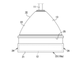
- FIG. 1 is a side view showing an ultrasonic transducer of the present invention
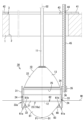
- FIG. Sectional drawing which shows the attachment for ultrasonic transducers in 1st Embodiment.
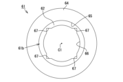
- the top view which shows a holding member. 4 is a graph showing the relationship between frequency and directivity angle in Examples 1 and 2 and Comparative Example. 4 is a graph showing the relationship between frequency and transmission/reception sensitivity in Examples 1 and 2 and Comparative Example.
- the top view which shows the positional relationship of a holding member and a horizontal maintenance instrument.
- Sectional drawing which shows the attachment for ultrasonic transducers in other embodiment.
- Sectional drawing which shows the attachment for ultrasonic transducers in other embodiment.
- the top view which shows the positional relationship of a holding member and a horizontal maintenance instrument in other embodiment.
- the top view which shows the positional relationship of a holding member and a horizontal maintenance instrument in other embodiment.
- (a) is a plan view showing the positional relationship between a holding member and a horizontal maintenance instrument in another embodiment
- (b) is an explanatory diagram showing a folding method of the horizontal maintenance instrument.
- the ultrasonic transducer 10 of this embodiment is a device for a fish finder that detects a school of fish existing in water by irradiating ultrasonic waves into water.
- the ultrasonic transmitter/receiver 10 is used while suspended from a cable 11 .
- the ultrasonic transmitter/receiver 10 also includes an ultrasonic transducer 12 that transmits and receives ultrasonic waves, and a case 13 that accommodates the ultrasonic transducer 12 in a molded state. Since the ultrasonic transducer 12 of the present embodiment is a composite transducer having a piezoelectric element such as a 0-3 composite structure, a 1-3 composite structure, and a 2-2 composite structure, the phases of the entire radiation surface are compared. It's on target.
- the case 13 has a bell shape, and has a lower case 21 forming the lower half of the case 13 and an upper case 22 forming the upper half of the case 13 .
- the lower case 21 is open at its upper end and has a bottom surface 23 and an outer peripheral surface 24 perpendicular to the bottom surface 23 .
- the ultrasonic transducer 12 is housed inside the lower case 21 .
- the outer diameter of the ultrasonic transducer 12 is slightly smaller than the outer diameter of the bottom surface 23 .
- a bottom surface 23 of the lower case 21 is flat and functions as an acoustic radiation surface 10a for irradiating (transmitting) ultrasonic waves.
- a groove portion 25 is formed on the outer peripheral surface 24 of the lower case 21 for fitting a screw 114 or the like shown in FIG.
- the groove portion 25 has a rectangular cross section, extends along the circumferential direction of the cylindrical lower case 21 , and is formed continuously over the entire circumference of the lower case 21 .
- the upper case 22 has a shape that is open at the lower end and whose outer diameter gradually decreases toward the upper end.
- a through hole (not shown) for inserting the cable 11 is provided in the upper end portion of the upper case 22 .
- the ultrasonic transducer 10 of this embodiment is used in a state of being suspended from the cable 11 during normal use (see FIG. 1).
- the ultrasonic transducer 10 can be used with the attachment 60 (see FIG. 2) attached.
- the attachment 60 includes an acoustic lens 81, a holding member 61, and a buoyancy body 71 (horizontal maintenance means).
- the holding member 61 is a substantially cylindrical member made of a resin material such as ABS resin, and is configured in a cup shape by a bottom portion 62, a cylindrical portion 63 and an upper end portion 64. .
- the holding member 61 detachably holds the ultrasonic transducer 10 so that the acoustic radiation surface 10 a is acoustically connected to the flat surface 82 of the acoustic lens 81 .
- a space formed by the bottom portion 62 and the cylindrical portion 63 serves as a holding concave portion 65 that holds the ultrasonic transmitter/receiver 10 .
- the inner diameter of the holding recess 65 (cylindrical portion 63 ) is slightly larger than the outer diameter of the ultrasonic transducer 10 .
- one fitting hole 66 is provided in the bottom portion 62 of the holding member 61 .
- the fitting hole 66 has a circular shape and is provided in the center of the bottom portion 62 .
- the fitting hole 66 is for fitting the convex surface 83 side of the acoustic lens 81 with the flat surface 82 facing up so as to protrude downward from the bottom surface 61 a (see FIG. 2) of the holding member 61 .
- the outer peripheral portion of the acoustic lens 81 is supported from below by the bottom portion 62 . Note that the acoustic lens 81 is detachably held with respect to the holding member 61 .
- Each water supply/discharge hole 67 has a corner portion at a position on the outer peripheral side of the bottom portion 62 .
- the water supply/discharge holes 67 are arranged at equal angular intervals (90° intervals) with the center C1 (see FIG. 3) of the fitting hole 66 as a reference.
- Each water supply/discharge hole 67 is for supplying water into the holding recess 65 and discharging the water inside the holding recess 65 to the outside of the holding member 61 .
- the buoyant body 71 is provided so as to surround the holding member 61 from the outer peripheral side. Specifically, the buoyant body 71 is attached so as to surround the outer wall surface 63a of the cylindrical portion 63 by winding a band plate-like sponge around the entire outer wall surface 63a.
- the buoyant body 71 is made of a material having a specific gravity smaller than that of water, such as polystyrene foam, polyethylene foam, and polyurethane foam.
- the buoyant body 71 horizontally maintains the holding member 61, the ultrasonic transmitter/receiver 10, and the acoustic lens 81 by the buoyant force acting on itself.
- the buoyant body 71 has enough buoyancy that the water surface W1 reaches the flat surface 82 of the acoustic lens 81 when the ultrasonic transducer 10 is not held in the holding recess 65 .
- the acoustic lens 81 is a substantially conical member made of urethane resin.
- the part of the ultrasonic wave transmitter/receiver 10 on the side of the acoustic radiation surface 10a is made of a molding material such as rubber or urethane resin. Therefore, the specific acoustic impedance of the acoustic lens 81 is approximately equal to the specific acoustic impedance of the molding material.
- the acoustic velocity of ultrasonic waves propagating in the acoustic lens 81 is different from the acoustic velocity of ultrasonic waves propagating through water.
- the acoustic lens 81 has a flat surface 82 and a convex surface 83 located on the opposite side.
- the outer diameter of the flat surface 82 is larger than the outer diameter of the fitting hole 66 and equal to the outer diameter of the acoustic radiation surface 10a. Therefore, the area of the flat surface 82 is equal to the area of the acoustic radiation surface 10a. Furthermore, the outer diameter of the flat surface 82 is slightly larger than the outer diameter of the ultrasonic transducer 12 housed in the lower case 21 of the ultrasonic transducer 10 .
- the tip region of the convex surface 83 (the region including the vertex P1 of the acoustic lens 81) is a spherical surface, and the convex surface 83 except for the tip region is an inclined surface.
- the entire spherical surface forming the convex surface 83 and a part of the inclined surface forming the convex surface 83 project downward from the bottom surface 61 a of the holding member 61 .
- a part of the inclined surface is supported by the opening end of the fitting hole 66 on the side of the upper surface 61b.
- the amount of deviation between the central axis O1 (the axis passing through the vertex P1) of the acoustic lens 81 and the central axis O2 of the ultrasonic transducer 10 is 2% or less of the external dimensions of the ultrasonic transducer 10 (this embodiment 0%). If the amount of deviation is greater than 2%, the center of gravity will be biased, and the holding member 61, the ultrasonic transmitter/receiver 10, and the acoustic lens 81 will tilt, and there is a risk that the ultrasonic waves will not travel directly downward.
- the holding recess 65 of the holding member 61 holds the acoustic lens 81 on the lower side and accommodates and holds the ultrasonic transducer 10 on the upper side.
- the acoustic lens 81 is arranged on the side of the acoustic radiation surface 10a of the ultrasonic transducer 10, and has a function of changing the directivity of the ultrasonic waves emitted from the acoustic radiation surface 10a.
- the ultrasonic transducer 10 of this embodiment is used for ice fishing such as smelt fishing.
- the ultrasonic transducer 10 is immersed in water while suspended by the cable 11 .
- Fish shoals are detected by transmission and reception of ultrasonic waves by the ultrasonic transducer 12 in the ultrasonic transducer 10 .
- the ultrasonic transmitter/receiver 10 and the liquid crystal monitor (not shown) are powered on.
- the liquid crystal monitor is used while being held by the user, for example.
- the liquid crystal monitor also has a control device (not shown) that controls the entire device.
- the control device is composed of a well-known computer comprising a CPU, ROM, RAM and the like.
- the CPU of the control device performs control to output an oscillation signal to the ultrasonic transducer 12 in the ultrasonic transducer 10 via the cable 11 to drive the ultrasonic transducer 12 .
- the ultrasonic transducer 12 vibrates, and the ultrasonic wave is irradiated (transmitted) from the ultrasonic transducer 12 and the acoustic radiation surface 10a of the ultrasonic transmitter/receiver 10 into the water.
- the ultrasonic waves reach the school of fish, the ultrasonic waves are reflected by the school of fish, become reflected waves, propagate toward the ultrasonic transducer 10 , and are input (received) by the ultrasonic transducer 12 .
- the ultrasonic waves (reflected waves) received by the ultrasonic transducer 12 are converted into received signals and input to the CPU via the cable 11 .
- the school of fish is detected.
- the irradiation of ultrasonic waves and the reception of reflected waves are terminated.
- the attachment 60 After attaching the attachment 60 to the ultrasonic transmitter/receiver 10, the attachment 60 is used in a state of being immersed in water (see FIG. 2). Specifically, first, the convex surface 83 side of the acoustic lens 81 with the flat surface 82 facing upward is fitted into the fitting hole 66 provided in the holding member 61 . As a result, the acoustic lens 81 is held below the holding recess 65 of the holding member 61 .
- the ultrasonic transmitter/receiver 10 with the acoustic radiation surface 10 a facing downward is inserted into the holding recess 65 , and the ultrasonic transmitter/receiver 10 is inserted into the fitting hole 66 on the flat surface 82 of the acoustic lens 81 fitted into the fitting hole 66 . place on top.
- the ultrasonic transmitter/receiver 10 is accommodated and held in the holding recess 65 , and the attachment 60 is attached to the ultrasonic transmitter/receiver 10 .
- the ultrasonic transducer 10 and the attachment 60 into water.
- water enters the holding recessed portion 65 from the four water supply/discharge holes 67 provided in the holding member 61, causing the flat surface 82 of the acoustic lens 81 and the acoustic radiation surface 10a of the ultrasonic transducer 10 to become flat. infiltrate in between.
- the flat surface 82 is in close contact (acoustically coupled) to the acoustic radiation surface 10a via the coupling material (here, water).
- the holding member 61 , the acoustic lens 81 and the ultrasonic transducer 10 float on the water and are maintained horizontally by the buoyant force acting on the buoyant body 71 .
- the CPU of the control device performs control to drive the ultrasonic transducer 12 in the ultrasonic transducer 10 .
- the ultrasonic transducer 12 vibrates, and ultrasonic waves are emitted (transmitted) from the acoustic radiation surface 10a of the ultrasonic transducer 10 into the water.
- the ultrasonic waves emitted from the acoustic emission surface 10a have a wide directivity angle when passing through the acoustic lens 81.
- FIG. As a result, the directional characteristics of the ultrasonic waves become wider than the original directional characteristics, so that it becomes possible to detect a school of fish in a wider range than usual.
- a sample for measurement was prepared as follows. An attachment provided with a conical acoustic lens (conical lens) was prepared and used as Example 1 (see “ ⁇ ” in FIGS. 4 and 5). Also, an attachment provided with a hemispherical acoustic lens (hemispherical lens) was prepared and used as Example 2 (see “ ⁇ ” in Figs. 4 and 5). On the other hand, an attachment without an acoustic lens was prepared and used as a comparative example (see “ ⁇ ” in FIGS. 4 and 5).
- Examples 1 and 2 and Comparative Example the directional characteristics of ultrasonic waves were verified for each measurement sample (Examples 1 and 2 and Comparative Example). Specifically, ultrasonic waves were emitted from an ultrasonic transducer in the ultrasonic transducer to which the attachment was attached, and the directional characteristics during irradiation (during transmission) were verified. In addition, the frequency was switched in a plurality of steps between 160 kHz and 300 kHz, and ultrasonic waves were applied at each switched frequency.
- FIG. 4 is a graph showing verification results of the directivity characteristics of ultrasonic waves.
- Example 1 which uses a conical acoustic lens, has a directional characteristic with a wider directivity angle than Example 2, which uses a hemispherical acoustic lens, at all frequencies.
- a voltage is applied to the ultrasonic transducer of each measurement sample (Examples 1 and 2 and Comparative Example), and the voltage is applied on the radiation center axis of the ultrasonic transducer and vertically below the ultrasonic transducer.
- the frequency was switched in a plurality of steps between 160 kHz and 300 kHz, and ultrasonic waves were applied at each switched frequency.
- Examples 1 and 2 which have a wide directivity angle for irradiating ultrasonic waves through an acoustic lens, have lower transmission/reception sensitivity than the comparative example, which has a narrow directivity angle because it does not have an acoustic lens, at all frequencies.
- Example 1 has a relatively wide directivity angle due to the use of a conical acoustic lens
- Example 2 has a relatively narrow directivity angle due to the use of a hemispherical acoustic lens.
- the ultrasonic transmitter/receiver 10 is held in the holding recess 65 of the holding member 61, and the ultrasonic transmitter/receiver 10 held in the holding recess 65 is An acoustic lens 81 is arranged on the side of the acoustic radiation surface 10a. In this case, even if there is only one ultrasonic transmitter/receiver 10, it is possible to change the directional characteristics of the ultrasonic waves emitted from the acoustic radiation surface 10a to different directional characteristics depending on the situation.
- the ultrasonic transmitter/receiver 10 by holding the ultrasonic transmitter/receiver 10 in the holding recess 65 , the directional characteristics (directivity angle) of the ultrasonic waves can be widened using the acoustic lens 81 .
- the directivity of ultrasonic waves can be changed to the original directivity.
- the buoyant body 71 is provided so as to surround the holding member 61 from the outer peripheral side simply by wrapping a strip-shaped sponge around the cylindrical portion 63 of the holding member 61 .
- the ultrasonic transducer 10 and the acoustic lens 81 can be horizontally maintained by the buoyant force acting on the buoyant body 71 without a complicated configuration such as the horizontal maintenance device 41 and the long screw 45 (see FIG. 6).
- the acoustic radiation surface 10a of the ultrasonic transducer 10 and the flat surface 82 of the acoustic lens 81 can be made horizontal. Moreover, even if the surface 3 (see FIG.
- the sound radiation surface 10a and the flat surface 82 can be leveled.
- the ultrasonic waves can be transmitted vertically downward, so the detection accuracy of the ultrasonic transmitter/receiver 10 is improved.
- the buoyant body 71 is provided so as to surround the holding member 61 from the outer peripheral side. easier to be As a result, the postures of the ultrasonic transducer 10 and the acoustic lens 81 held by the holding member 61 can be easily stabilized in water, and the acoustic radiation surface 10a of the ultrasonic transducer 10 and the acoustic lens 81 can be easily stabilized. Since the flat surface 82 is surely horizontal, the detection accuracy of the ultrasonic transducer 10 can be easily improved.
- the upper case 22 constituting the upper half of the case 13 has a shape that does not get caught, and the groove 25 formed in the lower case 21 constituting the lower half of the case 13 It has a shape that does not protrude from 21 . Therefore, the fishing line is less likely to get entangled in the case 13, particularly during normal ice fishing.
- the conical acoustic lens 81 is used as a member for changing the directivity of ultrasonic waves, it is possible to widen the directivity angle compared to, for example, using a hemispherical acoustic lens. (See Figure 4). If the acoustic lens 81 is simply conical, there is a problem that the sensitivity at a position vertically below the acoustic lens 81 on the center axis O1 of the acoustic lens 81 is lowered. Moreover, since it is difficult to form the tip of the cone with high precision, there is also the problem of increased product variation. Therefore, in the present embodiment, since the tip region of the convex surface 83 of the acoustic lens 81 is spherical, these problems can be resolved.
- the attachment 30 of this embodiment includes an acoustic lens 81, a holding member 31, and a horizontal maintenance device 41 (horizontal maintenance means).
- the holding member 31 is a substantially cylindrical member made of a resin material, and is formed into a cup shape by a bottom portion 32 and a cylindrical portion 33.
- a space formed by the bottom portion 32 and the cylindrical portion 33 serves as a holding recess portion 34 that detachably holds the ultrasonic transmitter/receiver 10 .
- a substantially cylindrical projecting portion 35 extending in the height direction of the cylindrical portion 33 is projected from the outer wall surface 33 a of the cylindrical portion 33 , and the projecting portion 35 is provided with a screw hole 36 .
- the horizontal maintenance tool 41 is a tool for keeping the holding member 31, the ultrasonic transmitter/receiver 10 and the acoustic lens 81 horizontal.
- the horizontal maintenance device 41 is installed at the opening of the circular hole 2 provided in the ice 1 (see FIG. 6).
- the horizontal maintenance device 41 is a plate-like member composed of a substantially annular frame body 42 that contacts the surface 3 of the ice 1 and an overhanging body 43 that overhangs the inner peripheral side of the frame body 42 .
- the projecting body 43 is provided with a screw insertion hole 44 . Furthermore, as shown in FIG.
- a horizontal maintenance device 41 and a holding member 41 are positioned at positions deviated from the center C1 of the fitting hole 66 and the center C2 of the frame 42 (in this embodiment, the position where the overhanging body 43 is located).
- a long screw 45 (bar-shaped member) that connects with the member 31 is arranged. The lower end of the long screw 45 is screwed into the screw hole 36 of the projecting portion 35, and the upper end of the long screw 45 is screwed into and inserted into the screw insertion hole 44 of the projecting body 43, thereby forming a holding member. 31, the ultrasonic transducer 10 and the acoustic lens 81 are maintained horizontally. Further, since the holding member 31 is arranged inside the frame 42 in plan view, the ultrasonic transducer 10 and the acoustic lens 81 held by the holding member 31 are also arranged inside the frame 42 .
- the ultrasonic transducer 10 In normal ice fishing, the ultrasonic transducer 10 is immersed in water while suspended by the cable 11. Fish shoals are detected by transmission and reception of ultrasonic waves by the ultrasonic transducer 12 in the ultrasonic transducer 10 .
- the ultrasonic transmitter/receiver 10 with the acoustic radiation surface 10 a facing downward is inserted into the holding recess 34 , and the ultrasonic transmitter/receiver 10 is inserted into the fitting hole 66 on the flat surface 82 of the acoustic lens 81 fitted into the fitting hole 66 . place on top.
- the ultrasonic transmitter/receiver 10 is accommodated and held in the holding recess 34 , and the attachment 30 is attached to the ultrasonic transmitter/receiver 10 .
- the horizontal maintenance device 41 is installed in the opening of the hole 2 provided in the ice 1, and the ultrasonic transducer 10 and the attachment 30 are put into the water.
- water enters the holding concave portion 34 from the four water supply/discharge holes 67 provided in the holding member 31, and the flat surface 82 of the acoustic lens 81 and the acoustic radiation surface 10a of the ultrasonic transducer 10 are separated from each other. infiltrate in between.
- the flat surface 82 is in close contact (acoustically coupled) to the acoustic radiation surface 10a via the coupling material (here, water).
- the ultrasonic transducer 12 in the ultrasonic transducer 10 is driven to irradiate (transmit) ultrasonic waves from the acoustic radiation surface 10a into the water.
- the ultrasonic waves emitted from the acoustic emission surface 10a have a wide directivity angle when passing through the acoustic lens 81.
- FIG. As a result, the directional characteristics of the ultrasonic waves become wider than the original directional characteristics, so that it becomes possible to detect a school of fish in a wider range than usual.
- the ultrasonic wave held by the holding member 31 is simply installed in the opening of the hole 2 provided in the ice 1 by simply installing the horizontal maintenance tool 41.
- the horizontal state of the transducer 10 and the acoustic lens 81 can be easily maintained.
- the level maintenance instrument 41 is supported by the solid ice 1, the horizontal state of the ultrasonic transmitter/receiver 10 and the acoustic lens 81 can be stably maintained.
- the ultrasonic transducer 10 (ultrasonic transducer 12) held by the holding member 31 is also inside the frame 42. That is, it is arranged close to the center of the hole 2 provided in the ice 1 . As a result, appropriate fish school detection can be performed directly under the hole 2 .
- the long screws 45 that connect the horizontal maintenance device 41 and the holding member 31 are arranged at positions shifted from the center C2 of the frame 42 . Therefore, when the ultrasonic transmitter/receiver 10 is attached to and detached from the holding member 31, the long screw 45 does not become an obstacle. Further, the long screw 45 is less likely to be entangled with the cable 11 for suspending the ultrasonic transducer 10, fishing line, or the like.
- the acoustic lens 81 of each of the above embodiments has a plurality of types that differ from each other in at least one of the dimensions (e.g., the diameter of the flat surface, the height from the center to the vertex of the flat surface, etc.) and the shape (e.g., the shape of the convex surface, etc.). acoustic lens.
- the fitting hole 92 may be formed so that the inner diameter gradually increases as it goes upward.
- the acoustic lens 81 in each of the above embodiments was placed in the holding recesses 34, 65 of the holding members 31, 61, but is fixed to the holding members 31, 61 by fitting or gluing. preferably. If it is not fixed to the holding members 31 and 61, when the ultrasonic transducer 10 is lifted, the attached acoustic lens 81 will be lifted together with the ultrasonic transducer 10, and there is a risk of dropping into the water. because there is
- an annular mounting fixture 101 is fixed to the inner peripheral side of the holding recess 65 of the holding member 61, and the mounting fixture 101 For example, the peripheral portion of the flat surface 82 of the acoustic lens 81 fitted in the fitting hole 66 is pressed. In this way, the acoustic lens 81 is fixed while being sandwiched between the holding member 61 and the mounting fixture 101, so that the acoustic lens 81 can be reliably fixed and held.
- a screw 114 (fastening member) is passed through a through-hole 113 provided in a cylindrical portion 112 of a holding member 111, and the tip of the screw 114 passing through the through-hole 113 is used to transmit and receive ultrasonic waves. It may be fitted in a groove 25 formed in the outer peripheral surface 24 of the wave device 10 . In this case, by fitting the screw 114 into the groove 25, it is possible to prevent the case 13 (ultrasonic transducer 10) and the acoustic lens 81 below it from coming off. 10 and the acoustic lens 81 can be reliably fixed and held.
- a permanent magnet may be provided in the groove 25, and a magnetic material such as a metal plate may be provided in the cylindrical portion 112 at a position facing the permanent magnet. Even in this case, the permanent magnets and the metal plate are attracted to each other and are in close contact with each other, so that the case 13 and the acoustic lens 81 can be prevented from coming off. Fixation and holding can be reliably performed. Note that if the screw 114 is not used, the through hole 113 and the groove 25 may not be provided.
- level maintenance instrument 41 of the second embodiment is composed of the substantially annular frame body 42, it may be composed of other shapes.
- leveling device 121 may consist of one strip 122 .
- the belt-shaped member 122 is provided with a screw insertion hole 44 for screwing and inserting the upper end portion of the long screw 45 .
- the horizontal maintenance device 131 may consist of a triangular frame 133 having a plurality of (here, three) sides 132 . Adjacent side portions 132 are connected via shaft portions 134 . A screw insertion hole 44 for screwing and inserting the upper end of a long screw 45 is provided in the central portion of one side portion 132 . In this way, the level maintenance device 131 can be stably attached to the opening of the hole 2 provided in the ice 1, compared to the case where the level maintenance device 131 consists of, for example, one belt-shaped member 122 (see FIG. 11). can be installed.
- the horizontal maintenance device 141 is composed of a square-shaped frame 143 having an even number of sides 142 of 4 or more (here, 4), and is foldable. good too.
- the diagonal length of the frame 143 is longer than the inner diameter of the hole 2 provided in the ice 1, and the lengths of the sides 142 are equal to each other.
- a screw insertion hole 44 for screwing and inserting the upper end of a long screw 45 is provided in the central portion of one side portion 142 .
- two shafts 144 positioned on the diagonal line of a square-shaped frame 143 are rotated so that the adjacent sides 142 overlap each other.
- the frame 143 is folded into a bar shape.
- the frame 143 folded into a rod shape is rotated around the shaft 144 positioned in the center so that the side portions 142 positioned on both sides of the shaft 144 overlap each other, the frame 143 can be folded in half. Folded to length.
- the level maintenance tool 141 (frame body 143) can be folded compactly, so that the level maintenance tool 141 can be easily carried.
- the long screw 45 is used as the rod-shaped member, but a metal rod or the like without thread grooves may be used as the rod-shaped member.
- water supply/discharge holes 67 were provided in the bottoms 32, 62 of the holding members 31, 61 in each of the above embodiments, but the number of water supply/discharge holes 67 may be five or more, or three. It may be one or less, or it may not be provided. Also, the water supply/discharge hole 67 is formed by widening a part of the fitting hole 66 , but it may be a hole independent of the fitting hole 66 .
- the case 13 of the ultrasonic transducer 10 is formed by joining the upper case 22 and the lower case 21, but the case is integrally formed. good too.
- the attachments 30 and 60 of the above-described embodiments are used for fish finders, but may be used for measuring instruments such as depth sounders for measuring the depth of water.
- the amount of deviation between the central axis of the acoustic lens and the central axis of the ultrasonic transducer is 2% or less of the outer diameter of the ultrasonic transducer.
- the buoyant body has buoyancy such that the water surface reaches the flat surface of the acoustic lens when the ultrasonic transducer is not held by the holding member.
- An attachment for an ultrasonic transducer characterized by: In this way, when the ultrasonic transducer is held by the holding member, the acoustic radiation surface of the ultrasonic transducer is reliably brought into contact with liquid (in this case, with water). Irradiation is not obstructed.
Landscapes
- Engineering & Computer Science (AREA)
- Radar, Positioning & Navigation (AREA)
- Remote Sensing (AREA)
- Physics & Mathematics (AREA)
- Computer Networks & Wireless Communication (AREA)
- General Physics & Mathematics (AREA)
- Acoustics & Sound (AREA)
- Measurement Of Velocity Or Position Using Acoustic Or Ultrasonic Waves (AREA)
- Transducers For Ultrasonic Waves (AREA)
Priority Applications (3)
| Application Number | Priority Date | Filing Date | Title |
|---|---|---|---|
| JP2022526737A JP7738241B2 (ja) | 2021-12-22 | 2021-12-22 | 超音波送受波器用のアタッチメント |
| PCT/JP2021/047559 WO2023119480A1 (ja) | 2021-12-22 | 2021-12-22 | 超音波送受波器用のアタッチメント |
| US17/915,715 US12253599B2 (en) | 2021-12-22 | 2021-12-22 | Attachment for ultrasonic-wave transmitter/receiver |
Applications Claiming Priority (1)
| Application Number | Priority Date | Filing Date | Title |
|---|---|---|---|
| PCT/JP2021/047559 WO2023119480A1 (ja) | 2021-12-22 | 2021-12-22 | 超音波送受波器用のアタッチメント |
Publications (1)
| Publication Number | Publication Date |
|---|---|
| WO2023119480A1 true WO2023119480A1 (ja) | 2023-06-29 |
Family
ID=86901662
Family Applications (1)
| Application Number | Title | Priority Date | Filing Date |
|---|---|---|---|
| PCT/JP2021/047559 Ceased WO2023119480A1 (ja) | 2021-12-22 | 2021-12-22 | 超音波送受波器用のアタッチメント |
Country Status (3)
| Country | Link |
|---|---|
| US (1) | US12253599B2 (https=) |
| JP (1) | JP7738241B2 (https=) |
| WO (1) | WO2023119480A1 (https=) |
Citations (11)
| Publication number | Priority date | Publication date | Assignee | Title |
|---|---|---|---|---|
| US4065748A (en) * | 1975-06-20 | 1977-12-27 | Etat Francais Represente Par Le Delegue Ministeriel Pour L'armement | Transmitting and receiving multipath sonar antenna utilizing a single acoustic lens |
| JPH0225885U (https=) * | 1988-08-05 | 1990-02-20 | ||
| US5173882A (en) * | 1992-04-02 | 1992-12-22 | Watson William D | Sonar system for and method of arctic seafloor reconnaissance |
| US5184414A (en) * | 1991-02-07 | 1993-02-09 | James Downs | Floating fishing light and transducer |
| US5546362A (en) * | 1995-05-15 | 1996-08-13 | Vexilar, Inc. | Depth finder transducer system |
| US5887376A (en) * | 1997-01-09 | 1999-03-30 | Lowrance Electronics, Inc. | Buoyant transducer assembly for assisting an angler |
| JP2002044773A (ja) * | 2000-07-28 | 2002-02-08 | Sonix Kk | 音響レンズおよび超音波送波器 |
| US20060050615A1 (en) * | 2004-09-03 | 2006-03-09 | Lowrance Electronics, Inc. | Transducer support and associated lock |
| US7746727B2 (en) * | 2008-05-12 | 2010-06-29 | Bacarella John P | Fish finder mounting bracket |
| US10712436B2 (en) * | 2017-10-19 | 2020-07-14 | Alexander Lebedev | Wireless fish finder sensor holder |
| US20210173061A1 (en) * | 2019-07-12 | 2021-06-10 | Airmar Technology Corporation | Broadband Ultrasonic Transducer Assembly with Acoustic Lens |
Family Cites Families (10)
| Publication number | Priority date | Publication date | Assignee | Title |
|---|---|---|---|---|
| JPS5985972A (ja) | 1982-11-08 | 1984-05-18 | Hitachi Medical Corp | 多重リング形超音波探触子 |
| JPH0225885A (ja) | 1988-07-14 | 1990-01-29 | Shinichi Hitomi | 看板の補修法 |
| JPH05212355A (ja) | 1992-02-06 | 1993-08-24 | Shimada Phys & Chem Ind Co Ltd | 振動体 |
| JP3367841B2 (ja) | 1996-03-06 | 2003-01-20 | 三菱重工業株式会社 | 超音波センサ |
| JP3741505B2 (ja) | 1996-12-26 | 2006-02-01 | 株式会社日立メディコ | 超音波探触子 |
| JP2001169393A (ja) | 1999-12-09 | 2001-06-22 | Kaijo Corp | 超音波振動子及びその製造方法 |
| US9322915B2 (en) * | 2012-02-22 | 2016-04-26 | Johnson Outdoors Inc. | 360 degree imaging sonar and method |
| US10325582B2 (en) * | 2016-07-28 | 2019-06-18 | Navico Holding As | Transducer mounting assembly |
| US11841427B2 (en) * | 2019-11-28 | 2023-12-12 | Honda Electronics Co., Ltd. | Ultrasonic-wave transmitter/receiver |
| US11762090B2 (en) * | 2020-05-20 | 2023-09-19 | Garmin Switzerland Gmbh | Ice transducer |
-
2021
- 2021-12-22 US US17/915,715 patent/US12253599B2/en active Active
- 2021-12-22 JP JP2022526737A patent/JP7738241B2/ja active Active
- 2021-12-22 WO PCT/JP2021/047559 patent/WO2023119480A1/ja not_active Ceased
Patent Citations (11)
| Publication number | Priority date | Publication date | Assignee | Title |
|---|---|---|---|---|
| US4065748A (en) * | 1975-06-20 | 1977-12-27 | Etat Francais Represente Par Le Delegue Ministeriel Pour L'armement | Transmitting and receiving multipath sonar antenna utilizing a single acoustic lens |
| JPH0225885U (https=) * | 1988-08-05 | 1990-02-20 | ||
| US5184414A (en) * | 1991-02-07 | 1993-02-09 | James Downs | Floating fishing light and transducer |
| US5173882A (en) * | 1992-04-02 | 1992-12-22 | Watson William D | Sonar system for and method of arctic seafloor reconnaissance |
| US5546362A (en) * | 1995-05-15 | 1996-08-13 | Vexilar, Inc. | Depth finder transducer system |
| US5887376A (en) * | 1997-01-09 | 1999-03-30 | Lowrance Electronics, Inc. | Buoyant transducer assembly for assisting an angler |
| JP2002044773A (ja) * | 2000-07-28 | 2002-02-08 | Sonix Kk | 音響レンズおよび超音波送波器 |
| US20060050615A1 (en) * | 2004-09-03 | 2006-03-09 | Lowrance Electronics, Inc. | Transducer support and associated lock |
| US7746727B2 (en) * | 2008-05-12 | 2010-06-29 | Bacarella John P | Fish finder mounting bracket |
| US10712436B2 (en) * | 2017-10-19 | 2020-07-14 | Alexander Lebedev | Wireless fish finder sensor holder |
| US20210173061A1 (en) * | 2019-07-12 | 2021-06-10 | Airmar Technology Corporation | Broadband Ultrasonic Transducer Assembly with Acoustic Lens |
Also Published As
| Publication number | Publication date |
|---|---|
| US12253599B2 (en) | 2025-03-18 |
| JPWO2023119480A1 (https=) | 2023-06-29 |
| JP7738241B2 (ja) | 2025-09-12 |
| US20240210562A1 (en) | 2024-06-27 |
Similar Documents
| Publication | Publication Date | Title |
|---|---|---|
| US11215489B2 (en) | Apparatus and method for measuring the flow velocity of a fluid in a pipe | |
| US4264788A (en) | Damped ultrasonic detection unit | |
| US5966983A (en) | Assembly for sensing and/or monitoring a predetermined level in a vessel | |
| EP2076061B1 (en) | Ultrasonic transducer | |
| CA3050631A1 (en) | Ultrasonic level sensor with reflector | |
| US20130180388A1 (en) | Percussion instrument apparatus, system and process | |
| US11002587B2 (en) | Ultrasonic level sensor with sound trap | |
| JP6991613B2 (ja) | 超音波送受波器 | |
| KR101951533B1 (ko) | 초음파 유량계 | |
| CN101919713B (zh) | 一种膀胱积尿量的测量方法 | |
| JP7738241B2 (ja) | 超音波送受波器用のアタッチメント | |
| US6081064A (en) | Acoustic transducer system | |
| JP7733919B2 (ja) | 超音波送受波器用のアタッチメント | |
| CN112697233A (zh) | 一种低盲区超声波物位传感器 | |
| JP2024079792A (ja) | 超音波トランスデューサ及び超音波トランスデューサの動作方法 | |
| CN211042411U (zh) | 一种用于化粪池的超声波液位监测装置和化粪池 | |
| JP6976010B2 (ja) | 超音波送受波器 | |
| JP2004233064A (ja) | 超音波送受波器 | |
| CN112781687A (zh) | 一种超声波物位传感器 | |
| JP7312420B1 (ja) | 計測機器用の超音波振動子 | |
| KR102801639B1 (ko) | 물리적 가변 특성을 가지는 수중 초음파센서 및 거리 측정 방법 | |
| JP4498312B2 (ja) | 水位検出装置並びに設備機器 | |
| JP2001343450A (ja) | 水中探知装置 | |
| EP3963373B1 (en) | A pressure coupling chamber for hydrophone calibration | |
| US20250172676A1 (en) | Ultrasonic-wave transmitter/receiver |
Legal Events
| Date | Code | Title | Description |
|---|---|---|---|
| WWE | Wipo information: entry into national phase |
Ref document number: 2022526737 Country of ref document: JP |
|
| WWE | Wipo information: entry into national phase |
Ref document number: 17915715 Country of ref document: US |
|
| 121 | Ep: the epo has been informed by wipo that ep was designated in this application |
Ref document number: 21968917 Country of ref document: EP Kind code of ref document: A1 |
|
| NENP | Non-entry into the national phase |
Ref country code: DE |
|
| 122 | Ep: pct application non-entry in european phase |
Ref document number: 21968917 Country of ref document: EP Kind code of ref document: A1 |
|
| WWG | Wipo information: grant in national office |
Ref document number: 17915715 Country of ref document: US |