WO2023119480A1 - 超音波送受波器用のアタッチメント - Google Patents
超音波送受波器用のアタッチメント Download PDFInfo
- Publication number
- WO2023119480A1 WO2023119480A1 PCT/JP2021/047559 JP2021047559W WO2023119480A1 WO 2023119480 A1 WO2023119480 A1 WO 2023119480A1 JP 2021047559 W JP2021047559 W JP 2021047559W WO 2023119480 A1 WO2023119480 A1 WO 2023119480A1
- Authority
- WO
- WIPO (PCT)
- Prior art keywords
- ultrasonic transducer
- acoustic lens
- holding member
- attachment
- ultrasonic
- Prior art date
Links
- XLYOFNOQVPJJNP-UHFFFAOYSA-N water Substances O XLYOFNOQVPJJNP-UHFFFAOYSA-N 0.000 claims description 59
- 238000012423 maintenance Methods 0.000 claims description 49
- 230000005855 radiation Effects 0.000 claims description 38
- 230000002093 peripheral effect Effects 0.000 claims description 18
- 241000251468 Actinopterygii Species 0.000 claims description 16
- 239000000463 material Substances 0.000 claims description 10
- 230000005484 gravity Effects 0.000 claims description 5
- 238000007599 discharging Methods 0.000 claims description 3
- 238000000034 method Methods 0.000 claims description 2
- 230000000052 comparative effect Effects 0.000 description 10
- 238000001514 detection method Methods 0.000 description 10
- WKVZMKDXJFCMMD-UVWUDEKDSA-L (5ar,8ar,9r)-5-[[(2r,4ar,6r,7r,8r,8as)-7,8-dihydroxy-2-methyl-4,4a,6,7,8,8a-hexahydropyrano[3,2-d][1,3]dioxin-6-yl]oxy]-9-(4-hydroxy-3,5-dimethoxyphenyl)-5a,6,8a,9-tetrahydro-5h-[2]benzofuro[6,5-f][1,3]benzodioxol-8-one;azanide;n,3-bis(2-chloroethyl)-2-ox Chemical compound [NH2-].[NH2-].Cl[Pt+2]Cl.ClCCNP1(=O)OCCCN1CCCl.COC1=C(O)C(OC)=CC([C@@H]2C3=CC=4OCOC=4C=C3C(O[C@H]3[C@@H]([C@@H](O)[C@@H]4O[C@H](C)OC[C@H]4O3)O)[C@@H]3[C@@H]2C(OC3)=O)=C1 WKVZMKDXJFCMMD-UVWUDEKDSA-L 0.000 description 9
- 230000005540 biological transmission Effects 0.000 description 9
- 230000035945 sensitivity Effects 0.000 description 9
- 238000003780 insertion Methods 0.000 description 5
- 230000037431 insertion Effects 0.000 description 5
- 239000002131 composite material Substances 0.000 description 4
- 230000001678 irradiating effect Effects 0.000 description 4
- 230000008878 coupling Effects 0.000 description 3
- 238000010168 coupling process Methods 0.000 description 3
- 238000005859 coupling reaction Methods 0.000 description 3
- 239000004973 liquid crystal related substance Substances 0.000 description 3
- 238000005259 measurement Methods 0.000 description 3
- 239000002184 metal Substances 0.000 description 3
- 241001062472 Stokellia anisodon Species 0.000 description 2
- 230000000694 effects Effects 0.000 description 2
- 239000012778 molding material Substances 0.000 description 2
- 230000036544 posture Effects 0.000 description 2
- 230000001902 propagating effect Effects 0.000 description 2
- 239000011347 resin Substances 0.000 description 2
- 229920005989 resin Polymers 0.000 description 2
- 239000007787 solid Substances 0.000 description 2
- 229920002803 thermoplastic polyurethane Polymers 0.000 description 2
- 239000004698 Polyethylene Substances 0.000 description 1
- 229920005830 Polyurethane Foam Polymers 0.000 description 1
- 229920000122 acrylonitrile butadiene styrene Polymers 0.000 description 1
- 238000004026 adhesive bonding Methods 0.000 description 1
- 238000007796 conventional method Methods 0.000 description 1
- 230000007423 decrease Effects 0.000 description 1
- 238000010586 diagram Methods 0.000 description 1
- 229920001971 elastomer Polymers 0.000 description 1
- 238000011156 evaluation Methods 0.000 description 1
- 239000006260 foam Substances 0.000 description 1
- 239000007788 liquid Substances 0.000 description 1
- 239000000696 magnetic material Substances 0.000 description 1
- 230000010355 oscillation Effects 0.000 description 1
- -1 polyethylene Polymers 0.000 description 1
- 229920000573 polyethylene Polymers 0.000 description 1
- 229920006327 polystyrene foam Polymers 0.000 description 1
- 239000011496 polyurethane foam Substances 0.000 description 1
- 230000008054 signal transmission Effects 0.000 description 1
- 238000012795 verification Methods 0.000 description 1
- 238000004804 winding Methods 0.000 description 1
Images


Classifications
-
- G—PHYSICS
- G01—MEASURING; TESTING
- G01S—RADIO DIRECTION-FINDING; RADIO NAVIGATION; DETERMINING DISTANCE OR VELOCITY BY USE OF RADIO WAVES; LOCATING OR PRESENCE-DETECTING BY USE OF THE REFLECTION OR RERADIATION OF RADIO WAVES; ANALOGOUS ARRANGEMENTS USING OTHER WAVES
- G01S15/00—Systems using the reflection or reradiation of acoustic waves, e.g. sonar systems
- G01S15/88—Sonar systems specially adapted for specific applications
- G01S15/96—Sonar systems specially adapted for specific applications for locating fish
-
- G—PHYSICS
- G01—MEASURING; TESTING
- G01S—RADIO DIRECTION-FINDING; RADIO NAVIGATION; DETERMINING DISTANCE OR VELOCITY BY USE OF RADIO WAVES; LOCATING OR PRESENCE-DETECTING BY USE OF THE REFLECTION OR RERADIATION OF RADIO WAVES; ANALOGOUS ARRANGEMENTS USING OTHER WAVES
- G01S7/00—Details of systems according to groups G01S13/00, G01S15/00, G01S17/00
- G01S7/52—Details of systems according to groups G01S13/00, G01S15/00, G01S17/00 of systems according to group G01S15/00
- G01S7/521—Constructional features
Definitions
- the present invention relates to an attachment attached to an ultrasonic transducer.
- an ultrasonic transducer housing an ultrasonic transducer is suspended by a cable for signal transmission and immersed in water, and an ultrasonic transducer that detects a school of fish by transmitting and receiving ultrasonic waves from the ultrasonic transducer. It has been known.
- This ultrasonic transducer is used, for example, in ice fishing such as smelt fishing.
- the ultrasonic transmitter/receiver is inserted into the water through a hole made in the ice during ice fishing.
- Japanese Patent Application Laid-Open No. 59-85972 (Figs. 2, 5, 6, etc.) Japanese Patent Application Laid-Open No. 5-212355 (claim 2, paragraphs [0012], [0023], FIG. 1, FIG. 2, etc.) JP-A-10-179582 (paragraph [0017], FIG. 1, etc.) Japanese Patent Application Laid-Open No. 2001-169393 (claims 1, 3, 4, paragraphs [0010], [0016], FIG. 1, FIG. 4, etc.) Japanese Patent Application Laid-Open No. 9-298795 (claim 3, paragraphs [0035], [0037], FIGS. 6 to 8, etc.)
- the ultrasonic transducer in order to improve the detection accuracy of the ultrasonic transducer, it is preferable to irradiate (transmit) the ultrasonic wave vertically downward with the acoustic emission surface of the ultrasonic transducer horizontal.
- the acoustic radiation surface is kept horizontal by the weight of the transducer.
- the ultrasonic transmitter/receiver is tilted, the acoustic radiation surface is also tilted, so the direction of the irradiated ultrasonic waves is tilted with respect to the vertical direction. In this case, since the school of fish cannot be detected accurately, there is a problem that an error occurs in the display on the fish finder.
- the present invention has been made in view of the above problems, and the first object is that even if there is only one ultrasonic transmitter/receiver, it can be used by changing it to a different directional characteristic depending on the situation.
- a second object of the present invention is to provide an attachment for an ultrasonic transducer capable of transmitting ultrasonic waves vertically downward and improving detection accuracy by maintaining the ultrasonic transducer horizontally. be.
- the invention according to claim 1 is a fish finder in which an ultrasonic transducer that is suspended from a cable and transmits and receives ultrasonic waves is housed in a molded state, and whose bottom surface is an acoustic radiation surface.
- a holding member for detachably holding the ultrasonic transducer so that the acoustic radiation surface is acoustically connected to the flat surface of the acoustic lens;
- the gist thereof is an attachment for an ultrasonic transducer, characterized by comprising a leveling means for keeping an acoustic lens horizontal.
- the ultrasonic transducer is detachably held by the holding member, and the acoustic lens is arranged on the acoustic radiation surface side of the ultrasonic transducer held by the holding member. be. Therefore, even if there is only one ultrasonic transmitter/receiver, it is possible to change the directional characteristics of the ultrasonic waves emitted from the acoustic radiation surface to different directional characteristics depending on the situation. Specifically, by holding the ultrasonic transmitter/receiver on the holding member, the directional characteristics of the ultrasonic waves can be changed using the acoustic lens.
- the directivity of the ultrasonic waves can be changed to the original directivity.
- the ultrasonic transducer and the acoustic lens are horizontally maintained by the horizontal maintenance means, the acoustic radiation surface of the ultrasonic transducer and the flat surface of the acoustic lens are also horizontal.
- the ultrasonic waves can be transmitted vertically downward, so that the detection accuracy of the ultrasonic transducer is improved.
- the convex surface of the acoustic lens may be a spherical surface, a conical surface, or the like.
- a horizontal maintenance device according to claim 1, wherein the horizontal maintenance means is installed in an opening of a hole provided in the ice, and maintains the ultrasonic transducer and the acoustic lens horizontally.
- the gist of it is that it is an instrument.
- the horizontal state of the ultrasonic transducer and the acoustic lens held by the holding member can be adjusted simply by installing the level maintenance device in the opening of the hole provided in the ice. Easy to maintain.
- the horizontality maintaining instrument is supported by solid ice, the horizontal state of the ultrasonic transducer and the acoustic lens can be stably maintained.
- the invention according to claim 3 is based on claim 2, wherein the level maintenance device comprises a frame body having a plurality of side portions, and the rod-shaped member connecting the level maintenance device and the holding member is formed by the frame body. and the holding member is arranged inside the frame.
- the level maintenance device is composed of a frame having a plurality of sides, the level maintenance device can be used to hold the ice as compared with the case where the level maintenance device is composed of, for example, one side. can be stably installed in the opening of the hole provided in the In addition, since the rod-shaped member that connects the horizontal maintenance device and the holding member is arranged at a position shifted from the center of the frame, the rod-shaped member interferes when attaching and detaching the ultrasonic transducer to and from the holding member. without becoming Furthermore, since the holding member is arranged inside the frame, the ultrasonic transmitter/receiver inserted from the inside of the frame can be easily held by the holding member.
- the diagonal length of the frame is preferably longer than the inner diameter of the hole provided in the ice. By doing so, it is possible to prevent the leveling instrument from falling into the hole.
- the gist of the invention according to claim 4 is that in claim 2 or 3, the horizontal maintenance device is made of a frame body having an even number of sides of 4 or more, and is foldable.
- the horizontal maintenance device (frame body) can be folded compactly, so that the horizontal maintenance device can be easily carried.
- the invention according to claim 5 is the invention according to claim 1, wherein the horizontal maintaining means is provided so as to surround the holding member from the outer peripheral side, is made of a material having a specific gravity smaller than that of water, and is made of a material having a specific gravity smaller than that of water.
- the gist of this is that it is a buoyant body that horizontally maintains the ultrasonic transducer and the acoustic lens.
- the horizontal maintaining means is a buoyant body provided so as to surround the holding member from the outer peripheral side, the buoyant force acts evenly on the holding member. slope is easily eliminated.
- the postures of the ultrasonic transducer and the acoustic lens held by the holding member in water can be easily stabilized, and the acoustic radiation surface of the ultrasonic transducer and the flat surface of the acoustic lens are reliably horizontal. Therefore, the detection accuracy of the ultrasonic transducer can be easily improved.
- the invention according to claim 6 is the acoustic lens according to any one of claims 1 to 5, wherein the acoustic lens is detachably held with respect to the holding member, and includes a plurality of types of acoustic lenses having at least one of different dimensions and shapes.
- the gist of it is that it is selected from acoustic lenses.
- the acoustic lens selected from a plurality of types of acoustic lenses is held by the holding member according to the situation.
- the directional characteristics of ultrasonic waves can be switched to various directional characteristics for use.
- the invention according to claim 7 is the holding member according to any one of claims 1 to 6, wherein the convex surface side of the acoustic lens with the flat surface facing upward is fitted into the bottom portion of the holding member.
- the gist of this is that a fitting hole for projecting downward from the bottom surface of the member is provided, and the fitting hole has a shape in which the inner diameter gradually increases as it goes upward.
- the ultrasonic transducer can be placed in the fitting hole. easier to put in.
- the invention according to claim 8 is the holding member according to any one of claims 1 to 6, wherein the convex surface side of the acoustic lens with the flat surface facing up is fitted into the bottom portion of the holding member.
- a fitting hole for projecting downward from the bottom surface of the member is provided, and a mounting fixture is provided which is fixed to the inner peripheral side of the holding member and presses the flat surface of the acoustic lens fitted in the fitting hole. This is the gist of it.
- the acoustic lens since the acoustic lens is fixed while being sandwiched between the bottom portion of the holding member and the mounting fixture, the acoustic lens can be securely fixed and held. Therefore, it is possible to solve the problem of the acoustic lens sticking to the ultrasonic transducer and falling into the water when the ultrasonic transducer is lifted.
- a ninth aspect of the invention is directed to the holding member according to any one of the first to sixth aspects, wherein the convex surface side of the acoustic lens with the flat surface facing upward is fitted into the bottom portion of the holding member.
- a fitting hole for projecting downward from the bottom surface of the member, and a water supply/discharge hole for supplying water into the holding member and discharging water from the holding member are provided, and the water supply/discharge hole.
- the ninth aspect of the invention when the attachment attached to the ultrasonic transducer is immersed in water, water is supplied into the holding member through the water supply/discharge hole, and the ultrasonic wave is transmitted and received. between the acoustic radiation surface of the instrument and the flat surface of the acoustic lens.
- the ultrasonic transducer and the acoustic lens can be used in close contact with each other through water as a coupling material, the directivity of ultrasonic waves can be made wider than the original directivity. can.
- the attachment when the attachment is lifted out of the water, the water can be smoothly discharged to the holding member side through the water supply/discharge hole.
- the invention according to claim 10 is based on any one of claims 1 to 9, wherein a groove portion extending in the circumferential direction of the ultrasonic transducer is formed on the outer peripheral surface of the ultrasonic transducer, and the groove portion The gist of this is that the fastening member passing through the holding member is fitted.
- the fastening member by fitting the fastening member into the groove, it is possible to prevent the ultrasonic transducer and the acoustic lens below it from coming off. It is possible to reliably fix and hold the instrument and the acoustic lens.
- FIG. 1 is a side view showing an ultrasonic transducer of the present invention
- FIG. Sectional drawing which shows the attachment for ultrasonic transducers in 1st Embodiment.
- the top view which shows a holding member. 4 is a graph showing the relationship between frequency and directivity angle in Examples 1 and 2 and Comparative Example. 4 is a graph showing the relationship between frequency and transmission/reception sensitivity in Examples 1 and 2 and Comparative Example.
- the top view which shows the positional relationship of a holding member and a horizontal maintenance instrument.
- Sectional drawing which shows the attachment for ultrasonic transducers in other embodiment.
- Sectional drawing which shows the attachment for ultrasonic transducers in other embodiment.
- the top view which shows the positional relationship of a holding member and a horizontal maintenance instrument in other embodiment.
- the top view which shows the positional relationship of a holding member and a horizontal maintenance instrument in other embodiment.
- (a) is a plan view showing the positional relationship between a holding member and a horizontal maintenance instrument in another embodiment
- (b) is an explanatory diagram showing a folding method of the horizontal maintenance instrument.
- the ultrasonic transducer 10 of this embodiment is a device for a fish finder that detects a school of fish existing in water by irradiating ultrasonic waves into water.
- the ultrasonic transmitter/receiver 10 is used while suspended from a cable 11 .
- the ultrasonic transmitter/receiver 10 also includes an ultrasonic transducer 12 that transmits and receives ultrasonic waves, and a case 13 that accommodates the ultrasonic transducer 12 in a molded state. Since the ultrasonic transducer 12 of the present embodiment is a composite transducer having a piezoelectric element such as a 0-3 composite structure, a 1-3 composite structure, and a 2-2 composite structure, the phases of the entire radiation surface are compared. It's on target.
- the case 13 has a bell shape, and has a lower case 21 forming the lower half of the case 13 and an upper case 22 forming the upper half of the case 13 .
- the lower case 21 is open at its upper end and has a bottom surface 23 and an outer peripheral surface 24 perpendicular to the bottom surface 23 .
- the ultrasonic transducer 12 is housed inside the lower case 21 .
- the outer diameter of the ultrasonic transducer 12 is slightly smaller than the outer diameter of the bottom surface 23 .
- a bottom surface 23 of the lower case 21 is flat and functions as an acoustic radiation surface 10a for irradiating (transmitting) ultrasonic waves.
- a groove portion 25 is formed on the outer peripheral surface 24 of the lower case 21 for fitting a screw 114 or the like shown in FIG.
- the groove portion 25 has a rectangular cross section, extends along the circumferential direction of the cylindrical lower case 21 , and is formed continuously over the entire circumference of the lower case 21 .
- the upper case 22 has a shape that is open at the lower end and whose outer diameter gradually decreases toward the upper end.
- a through hole (not shown) for inserting the cable 11 is provided in the upper end portion of the upper case 22 .
- the ultrasonic transducer 10 of this embodiment is used in a state of being suspended from the cable 11 during normal use (see FIG. 1).
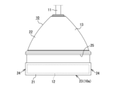
- the ultrasonic transducer 10 can be used with the attachment 60 (see FIG. 2) attached.
- the attachment 60 includes an acoustic lens 81, a holding member 61, and a buoyancy body 71 (horizontal maintenance means).
- the holding member 61 is a substantially cylindrical member made of a resin material such as ABS resin, and is configured in a cup shape by a bottom portion 62, a cylindrical portion 63 and an upper end portion 64. .
- the holding member 61 detachably holds the ultrasonic transducer 10 so that the acoustic radiation surface 10 a is acoustically connected to the flat surface 82 of the acoustic lens 81 .
- a space formed by the bottom portion 62 and the cylindrical portion 63 serves as a holding concave portion 65 that holds the ultrasonic transmitter/receiver 10 .
- the inner diameter of the holding recess 65 (cylindrical portion 63 ) is slightly larger than the outer diameter of the ultrasonic transducer 10 .
- one fitting hole 66 is provided in the bottom portion 62 of the holding member 61 .
- the fitting hole 66 has a circular shape and is provided in the center of the bottom portion 62 .
- the fitting hole 66 is for fitting the convex surface 83 side of the acoustic lens 81 with the flat surface 82 facing up so as to protrude downward from the bottom surface 61 a (see FIG. 2) of the holding member 61 .
- the outer peripheral portion of the acoustic lens 81 is supported from below by the bottom portion 62 . Note that the acoustic lens 81 is detachably held with respect to the holding member 61 .
- Each water supply/discharge hole 67 has a corner portion at a position on the outer peripheral side of the bottom portion 62 .
- the water supply/discharge holes 67 are arranged at equal angular intervals (90° intervals) with the center C1 (see FIG. 3) of the fitting hole 66 as a reference.
- Each water supply/discharge hole 67 is for supplying water into the holding recess 65 and discharging the water inside the holding recess 65 to the outside of the holding member 61 .
- the buoyant body 71 is provided so as to surround the holding member 61 from the outer peripheral side. Specifically, the buoyant body 71 is attached so as to surround the outer wall surface 63a of the cylindrical portion 63 by winding a band plate-like sponge around the entire outer wall surface 63a.
- the buoyant body 71 is made of a material having a specific gravity smaller than that of water, such as polystyrene foam, polyethylene foam, and polyurethane foam.
- the buoyant body 71 horizontally maintains the holding member 61, the ultrasonic transmitter/receiver 10, and the acoustic lens 81 by the buoyant force acting on itself.
- the buoyant body 71 has enough buoyancy that the water surface W1 reaches the flat surface 82 of the acoustic lens 81 when the ultrasonic transducer 10 is not held in the holding recess 65 .
- the acoustic lens 81 is a substantially conical member made of urethane resin.
- the part of the ultrasonic wave transmitter/receiver 10 on the side of the acoustic radiation surface 10a is made of a molding material such as rubber or urethane resin. Therefore, the specific acoustic impedance of the acoustic lens 81 is approximately equal to the specific acoustic impedance of the molding material.
- the acoustic velocity of ultrasonic waves propagating in the acoustic lens 81 is different from the acoustic velocity of ultrasonic waves propagating through water.
- the acoustic lens 81 has a flat surface 82 and a convex surface 83 located on the opposite side.
- the outer diameter of the flat surface 82 is larger than the outer diameter of the fitting hole 66 and equal to the outer diameter of the acoustic radiation surface 10a. Therefore, the area of the flat surface 82 is equal to the area of the acoustic radiation surface 10a. Furthermore, the outer diameter of the flat surface 82 is slightly larger than the outer diameter of the ultrasonic transducer 12 housed in the lower case 21 of the ultrasonic transducer 10 .
- the tip region of the convex surface 83 (the region including the vertex P1 of the acoustic lens 81) is a spherical surface, and the convex surface 83 except for the tip region is an inclined surface.
- the entire spherical surface forming the convex surface 83 and a part of the inclined surface forming the convex surface 83 project downward from the bottom surface 61 a of the holding member 61 .
- a part of the inclined surface is supported by the opening end of the fitting hole 66 on the side of the upper surface 61b.
- the amount of deviation between the central axis O1 (the axis passing through the vertex P1) of the acoustic lens 81 and the central axis O2 of the ultrasonic transducer 10 is 2% or less of the external dimensions of the ultrasonic transducer 10 (this embodiment 0%). If the amount of deviation is greater than 2%, the center of gravity will be biased, and the holding member 61, the ultrasonic transmitter/receiver 10, and the acoustic lens 81 will tilt, and there is a risk that the ultrasonic waves will not travel directly downward.
- the holding recess 65 of the holding member 61 holds the acoustic lens 81 on the lower side and accommodates and holds the ultrasonic transducer 10 on the upper side.
- the acoustic lens 81 is arranged on the side of the acoustic radiation surface 10a of the ultrasonic transducer 10, and has a function of changing the directivity of the ultrasonic waves emitted from the acoustic radiation surface 10a.
- the ultrasonic transducer 10 of this embodiment is used for ice fishing such as smelt fishing.
- the ultrasonic transducer 10 is immersed in water while suspended by the cable 11 .
- Fish shoals are detected by transmission and reception of ultrasonic waves by the ultrasonic transducer 12 in the ultrasonic transducer 10 .
- the ultrasonic transmitter/receiver 10 and the liquid crystal monitor (not shown) are powered on.
- the liquid crystal monitor is used while being held by the user, for example.
- the liquid crystal monitor also has a control device (not shown) that controls the entire device.
- the control device is composed of a well-known computer comprising a CPU, ROM, RAM and the like.
- the CPU of the control device performs control to output an oscillation signal to the ultrasonic transducer 12 in the ultrasonic transducer 10 via the cable 11 to drive the ultrasonic transducer 12 .
- the ultrasonic transducer 12 vibrates, and the ultrasonic wave is irradiated (transmitted) from the ultrasonic transducer 12 and the acoustic radiation surface 10a of the ultrasonic transmitter/receiver 10 into the water.
- the ultrasonic waves reach the school of fish, the ultrasonic waves are reflected by the school of fish, become reflected waves, propagate toward the ultrasonic transducer 10 , and are input (received) by the ultrasonic transducer 12 .
- the ultrasonic waves (reflected waves) received by the ultrasonic transducer 12 are converted into received signals and input to the CPU via the cable 11 .
- the school of fish is detected.
- the irradiation of ultrasonic waves and the reception of reflected waves are terminated.
- the attachment 60 After attaching the attachment 60 to the ultrasonic transmitter/receiver 10, the attachment 60 is used in a state of being immersed in water (see FIG. 2). Specifically, first, the convex surface 83 side of the acoustic lens 81 with the flat surface 82 facing upward is fitted into the fitting hole 66 provided in the holding member 61 . As a result, the acoustic lens 81 is held below the holding recess 65 of the holding member 61 .
- the ultrasonic transmitter/receiver 10 with the acoustic radiation surface 10 a facing downward is inserted into the holding recess 65 , and the ultrasonic transmitter/receiver 10 is inserted into the fitting hole 66 on the flat surface 82 of the acoustic lens 81 fitted into the fitting hole 66 . place on top.
- the ultrasonic transmitter/receiver 10 is accommodated and held in the holding recess 65 , and the attachment 60 is attached to the ultrasonic transmitter/receiver 10 .
- the ultrasonic transducer 10 and the attachment 60 into water.
- water enters the holding recessed portion 65 from the four water supply/discharge holes 67 provided in the holding member 61, causing the flat surface 82 of the acoustic lens 81 and the acoustic radiation surface 10a of the ultrasonic transducer 10 to become flat. infiltrate in between.
- the flat surface 82 is in close contact (acoustically coupled) to the acoustic radiation surface 10a via the coupling material (here, water).
- the holding member 61 , the acoustic lens 81 and the ultrasonic transducer 10 float on the water and are maintained horizontally by the buoyant force acting on the buoyant body 71 .
- the CPU of the control device performs control to drive the ultrasonic transducer 12 in the ultrasonic transducer 10 .
- the ultrasonic transducer 12 vibrates, and ultrasonic waves are emitted (transmitted) from the acoustic radiation surface 10a of the ultrasonic transducer 10 into the water.
- the ultrasonic waves emitted from the acoustic emission surface 10a have a wide directivity angle when passing through the acoustic lens 81.
- FIG. As a result, the directional characteristics of the ultrasonic waves become wider than the original directional characteristics, so that it becomes possible to detect a school of fish in a wider range than usual.
- a sample for measurement was prepared as follows. An attachment provided with a conical acoustic lens (conical lens) was prepared and used as Example 1 (see “ ⁇ ” in FIGS. 4 and 5). Also, an attachment provided with a hemispherical acoustic lens (hemispherical lens) was prepared and used as Example 2 (see “ ⁇ ” in Figs. 4 and 5). On the other hand, an attachment without an acoustic lens was prepared and used as a comparative example (see “ ⁇ ” in FIGS. 4 and 5).
- Examples 1 and 2 and Comparative Example the directional characteristics of ultrasonic waves were verified for each measurement sample (Examples 1 and 2 and Comparative Example). Specifically, ultrasonic waves were emitted from an ultrasonic transducer in the ultrasonic transducer to which the attachment was attached, and the directional characteristics during irradiation (during transmission) were verified. In addition, the frequency was switched in a plurality of steps between 160 kHz and 300 kHz, and ultrasonic waves were applied at each switched frequency.
- FIG. 4 is a graph showing verification results of the directivity characteristics of ultrasonic waves.
- Example 1 which uses a conical acoustic lens, has a directional characteristic with a wider directivity angle than Example 2, which uses a hemispherical acoustic lens, at all frequencies.
- a voltage is applied to the ultrasonic transducer of each measurement sample (Examples 1 and 2 and Comparative Example), and the voltage is applied on the radiation center axis of the ultrasonic transducer and vertically below the ultrasonic transducer.
- the frequency was switched in a plurality of steps between 160 kHz and 300 kHz, and ultrasonic waves were applied at each switched frequency.
- Examples 1 and 2 which have a wide directivity angle for irradiating ultrasonic waves through an acoustic lens, have lower transmission/reception sensitivity than the comparative example, which has a narrow directivity angle because it does not have an acoustic lens, at all frequencies.
- Example 1 has a relatively wide directivity angle due to the use of a conical acoustic lens
- Example 2 has a relatively narrow directivity angle due to the use of a hemispherical acoustic lens.
- the ultrasonic transmitter/receiver 10 is held in the holding recess 65 of the holding member 61, and the ultrasonic transmitter/receiver 10 held in the holding recess 65 is An acoustic lens 81 is arranged on the side of the acoustic radiation surface 10a. In this case, even if there is only one ultrasonic transmitter/receiver 10, it is possible to change the directional characteristics of the ultrasonic waves emitted from the acoustic radiation surface 10a to different directional characteristics depending on the situation.
- the ultrasonic transmitter/receiver 10 by holding the ultrasonic transmitter/receiver 10 in the holding recess 65 , the directional characteristics (directivity angle) of the ultrasonic waves can be widened using the acoustic lens 81 .
- the directivity of ultrasonic waves can be changed to the original directivity.
- the buoyant body 71 is provided so as to surround the holding member 61 from the outer peripheral side simply by wrapping a strip-shaped sponge around the cylindrical portion 63 of the holding member 61 .
- the ultrasonic transducer 10 and the acoustic lens 81 can be horizontally maintained by the buoyant force acting on the buoyant body 71 without a complicated configuration such as the horizontal maintenance device 41 and the long screw 45 (see FIG. 6).
- the acoustic radiation surface 10a of the ultrasonic transducer 10 and the flat surface 82 of the acoustic lens 81 can be made horizontal. Moreover, even if the surface 3 (see FIG.
- the sound radiation surface 10a and the flat surface 82 can be leveled.
- the ultrasonic waves can be transmitted vertically downward, so the detection accuracy of the ultrasonic transmitter/receiver 10 is improved.
- the buoyant body 71 is provided so as to surround the holding member 61 from the outer peripheral side. easier to be As a result, the postures of the ultrasonic transducer 10 and the acoustic lens 81 held by the holding member 61 can be easily stabilized in water, and the acoustic radiation surface 10a of the ultrasonic transducer 10 and the acoustic lens 81 can be easily stabilized. Since the flat surface 82 is surely horizontal, the detection accuracy of the ultrasonic transducer 10 can be easily improved.
- the upper case 22 constituting the upper half of the case 13 has a shape that does not get caught, and the groove 25 formed in the lower case 21 constituting the lower half of the case 13 It has a shape that does not protrude from 21 . Therefore, the fishing line is less likely to get entangled in the case 13, particularly during normal ice fishing.
- the conical acoustic lens 81 is used as a member for changing the directivity of ultrasonic waves, it is possible to widen the directivity angle compared to, for example, using a hemispherical acoustic lens. (See Figure 4). If the acoustic lens 81 is simply conical, there is a problem that the sensitivity at a position vertically below the acoustic lens 81 on the center axis O1 of the acoustic lens 81 is lowered. Moreover, since it is difficult to form the tip of the cone with high precision, there is also the problem of increased product variation. Therefore, in the present embodiment, since the tip region of the convex surface 83 of the acoustic lens 81 is spherical, these problems can be resolved.
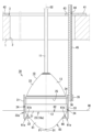
- the attachment 30 of this embodiment includes an acoustic lens 81, a holding member 31, and a horizontal maintenance device 41 (horizontal maintenance means).
- the holding member 31 is a substantially cylindrical member made of a resin material, and is formed into a cup shape by a bottom portion 32 and a cylindrical portion 33.
- a space formed by the bottom portion 32 and the cylindrical portion 33 serves as a holding recess portion 34 that detachably holds the ultrasonic transmitter/receiver 10 .
- a substantially cylindrical projecting portion 35 extending in the height direction of the cylindrical portion 33 is projected from the outer wall surface 33 a of the cylindrical portion 33 , and the projecting portion 35 is provided with a screw hole 36 .
- the horizontal maintenance tool 41 is a tool for keeping the holding member 31, the ultrasonic transmitter/receiver 10 and the acoustic lens 81 horizontal.
- the horizontal maintenance device 41 is installed at the opening of the circular hole 2 provided in the ice 1 (see FIG. 6).
- the horizontal maintenance device 41 is a plate-like member composed of a substantially annular frame body 42 that contacts the surface 3 of the ice 1 and an overhanging body 43 that overhangs the inner peripheral side of the frame body 42 .
- the projecting body 43 is provided with a screw insertion hole 44 . Furthermore, as shown in FIG.
- a horizontal maintenance device 41 and a holding member 41 are positioned at positions deviated from the center C1 of the fitting hole 66 and the center C2 of the frame 42 (in this embodiment, the position where the overhanging body 43 is located).
- a long screw 45 (bar-shaped member) that connects with the member 31 is arranged. The lower end of the long screw 45 is screwed into the screw hole 36 of the projecting portion 35, and the upper end of the long screw 45 is screwed into and inserted into the screw insertion hole 44 of the projecting body 43, thereby forming a holding member. 31, the ultrasonic transducer 10 and the acoustic lens 81 are maintained horizontally. Further, since the holding member 31 is arranged inside the frame 42 in plan view, the ultrasonic transducer 10 and the acoustic lens 81 held by the holding member 31 are also arranged inside the frame 42 .
- the ultrasonic transducer 10 In normal ice fishing, the ultrasonic transducer 10 is immersed in water while suspended by the cable 11. Fish shoals are detected by transmission and reception of ultrasonic waves by the ultrasonic transducer 12 in the ultrasonic transducer 10 .
- the ultrasonic transmitter/receiver 10 with the acoustic radiation surface 10 a facing downward is inserted into the holding recess 34 , and the ultrasonic transmitter/receiver 10 is inserted into the fitting hole 66 on the flat surface 82 of the acoustic lens 81 fitted into the fitting hole 66 . place on top.
- the ultrasonic transmitter/receiver 10 is accommodated and held in the holding recess 34 , and the attachment 30 is attached to the ultrasonic transmitter/receiver 10 .
- the horizontal maintenance device 41 is installed in the opening of the hole 2 provided in the ice 1, and the ultrasonic transducer 10 and the attachment 30 are put into the water.
- water enters the holding concave portion 34 from the four water supply/discharge holes 67 provided in the holding member 31, and the flat surface 82 of the acoustic lens 81 and the acoustic radiation surface 10a of the ultrasonic transducer 10 are separated from each other. infiltrate in between.
- the flat surface 82 is in close contact (acoustically coupled) to the acoustic radiation surface 10a via the coupling material (here, water).
- the ultrasonic transducer 12 in the ultrasonic transducer 10 is driven to irradiate (transmit) ultrasonic waves from the acoustic radiation surface 10a into the water.
- the ultrasonic waves emitted from the acoustic emission surface 10a have a wide directivity angle when passing through the acoustic lens 81.
- FIG. As a result, the directional characteristics of the ultrasonic waves become wider than the original directional characteristics, so that it becomes possible to detect a school of fish in a wider range than usual.
- the ultrasonic wave held by the holding member 31 is simply installed in the opening of the hole 2 provided in the ice 1 by simply installing the horizontal maintenance tool 41.
- the horizontal state of the transducer 10 and the acoustic lens 81 can be easily maintained.
- the level maintenance instrument 41 is supported by the solid ice 1, the horizontal state of the ultrasonic transmitter/receiver 10 and the acoustic lens 81 can be stably maintained.
- the ultrasonic transducer 10 (ultrasonic transducer 12) held by the holding member 31 is also inside the frame 42. That is, it is arranged close to the center of the hole 2 provided in the ice 1 . As a result, appropriate fish school detection can be performed directly under the hole 2 .
- the long screws 45 that connect the horizontal maintenance device 41 and the holding member 31 are arranged at positions shifted from the center C2 of the frame 42 . Therefore, when the ultrasonic transmitter/receiver 10 is attached to and detached from the holding member 31, the long screw 45 does not become an obstacle. Further, the long screw 45 is less likely to be entangled with the cable 11 for suspending the ultrasonic transducer 10, fishing line, or the like.
- the acoustic lens 81 of each of the above embodiments has a plurality of types that differ from each other in at least one of the dimensions (e.g., the diameter of the flat surface, the height from the center to the vertex of the flat surface, etc.) and the shape (e.g., the shape of the convex surface, etc.). acoustic lens.
- the fitting hole 92 may be formed so that the inner diameter gradually increases as it goes upward.
- the acoustic lens 81 in each of the above embodiments was placed in the holding recesses 34, 65 of the holding members 31, 61, but is fixed to the holding members 31, 61 by fitting or gluing. preferably. If it is not fixed to the holding members 31 and 61, when the ultrasonic transducer 10 is lifted, the attached acoustic lens 81 will be lifted together with the ultrasonic transducer 10, and there is a risk of dropping into the water. because there is
- an annular mounting fixture 101 is fixed to the inner peripheral side of the holding recess 65 of the holding member 61, and the mounting fixture 101 For example, the peripheral portion of the flat surface 82 of the acoustic lens 81 fitted in the fitting hole 66 is pressed. In this way, the acoustic lens 81 is fixed while being sandwiched between the holding member 61 and the mounting fixture 101, so that the acoustic lens 81 can be reliably fixed and held.
- a screw 114 (fastening member) is passed through a through-hole 113 provided in a cylindrical portion 112 of a holding member 111, and the tip of the screw 114 passing through the through-hole 113 is used to transmit and receive ultrasonic waves. It may be fitted in a groove 25 formed in the outer peripheral surface 24 of the wave device 10 . In this case, by fitting the screw 114 into the groove 25, it is possible to prevent the case 13 (ultrasonic transducer 10) and the acoustic lens 81 below it from coming off. 10 and the acoustic lens 81 can be reliably fixed and held.
- a permanent magnet may be provided in the groove 25, and a magnetic material such as a metal plate may be provided in the cylindrical portion 112 at a position facing the permanent magnet. Even in this case, the permanent magnets and the metal plate are attracted to each other and are in close contact with each other, so that the case 13 and the acoustic lens 81 can be prevented from coming off. Fixation and holding can be reliably performed. Note that if the screw 114 is not used, the through hole 113 and the groove 25 may not be provided.
- level maintenance instrument 41 of the second embodiment is composed of the substantially annular frame body 42, it may be composed of other shapes.
- leveling device 121 may consist of one strip 122 .
- the belt-shaped member 122 is provided with a screw insertion hole 44 for screwing and inserting the upper end portion of the long screw 45 .
- the horizontal maintenance device 131 may consist of a triangular frame 133 having a plurality of (here, three) sides 132 . Adjacent side portions 132 are connected via shaft portions 134 . A screw insertion hole 44 for screwing and inserting the upper end of a long screw 45 is provided in the central portion of one side portion 132 . In this way, the level maintenance device 131 can be stably attached to the opening of the hole 2 provided in the ice 1, compared to the case where the level maintenance device 131 consists of, for example, one belt-shaped member 122 (see FIG. 11). can be installed.
- the horizontal maintenance device 141 is composed of a square-shaped frame 143 having an even number of sides 142 of 4 or more (here, 4), and is foldable. good too.
- the diagonal length of the frame 143 is longer than the inner diameter of the hole 2 provided in the ice 1, and the lengths of the sides 142 are equal to each other.
- a screw insertion hole 44 for screwing and inserting the upper end of a long screw 45 is provided in the central portion of one side portion 142 .
- two shafts 144 positioned on the diagonal line of a square-shaped frame 143 are rotated so that the adjacent sides 142 overlap each other.
- the frame 143 is folded into a bar shape.
- the frame 143 folded into a rod shape is rotated around the shaft 144 positioned in the center so that the side portions 142 positioned on both sides of the shaft 144 overlap each other, the frame 143 can be folded in half. Folded to length.
- the level maintenance tool 141 (frame body 143) can be folded compactly, so that the level maintenance tool 141 can be easily carried.
- the long screw 45 is used as the rod-shaped member, but a metal rod or the like without thread grooves may be used as the rod-shaped member.
- water supply/discharge holes 67 were provided in the bottoms 32, 62 of the holding members 31, 61 in each of the above embodiments, but the number of water supply/discharge holes 67 may be five or more, or three. It may be one or less, or it may not be provided. Also, the water supply/discharge hole 67 is formed by widening a part of the fitting hole 66 , but it may be a hole independent of the fitting hole 66 .
- the case 13 of the ultrasonic transducer 10 is formed by joining the upper case 22 and the lower case 21, but the case is integrally formed. good too.
- the attachments 30 and 60 of the above-described embodiments are used for fish finders, but may be used for measuring instruments such as depth sounders for measuring the depth of water.
- the amount of deviation between the central axis of the acoustic lens and the central axis of the ultrasonic transducer is 2% or less of the outer diameter of the ultrasonic transducer.
- the buoyant body has buoyancy such that the water surface reaches the flat surface of the acoustic lens when the ultrasonic transducer is not held by the holding member.
- An attachment for an ultrasonic transducer characterized by: In this way, when the ultrasonic transducer is held by the holding member, the acoustic radiation surface of the ultrasonic transducer is reliably brought into contact with liquid (in this case, with water). Irradiation is not obstructed.
Landscapes
- Engineering & Computer Science (AREA)
- Radar, Positioning & Navigation (AREA)
- Remote Sensing (AREA)
- Physics & Mathematics (AREA)
- Computer Networks & Wireless Communication (AREA)
- General Physics & Mathematics (AREA)
- Acoustics & Sound (AREA)
- Measurement Of Velocity Or Position Using Acoustic Or Ultrasonic Waves (AREA)
- Transducers For Ultrasonic Waves (AREA)
Abstract
超音波送受波器が1つしかなくても、状況に応じて異なる指向特性に変更して使用できる超音波送受波器用のアタッチメントを提供する。超音波送受波器10に対して取り付けられる本発明のアタッチメント60は、音響レンズ81、保持部材61及び水平維持手段71を備える。音響レンズ81は、平坦面82及びその反対側に位置する凸面83を有する。保持部材61は、平坦面82を上にした状態の音響レンズ81を保持するとともに、音響放射面10aが平坦面82に音響的に接続された状態となるように、超音波送受波器10を着脱可能に保持する。水平維持手段71は、超音波送受波器10及び音響レンズ81を水平に維持する。
Description
本発明は、超音波送受波器に対して取り付けられるアタッチメントに関するものである。
従来、超音波振動子が収容された超音波送受波器を、信号伝送用のケーブルで吊り下げて水中に浸漬し、超音波振動子による超音波の送受信により魚群探知を行う超音波送受波器が知られている。この超音波送受波器は、例えば、ワカサギ釣りなどのアイスフィッシングで用いられている。なお、超音波送受波器は、アイスフィッシングにおいて氷に開けられた孔から水中に挿入されるものである。
ところで、超音波振動子から照射される超音波の指向特性を調整(変更)したいという要望がある。なお、従来では、超音波の指向特性を変更させる部材として、凸面または凹面を有する音響レンズ(例えば、特許文献1~5参照)を用いることが提案されている。
しかしながら、特許文献1~5に記載の従来技術では、超音波振動子に対して音響レンズが直接取り付けられている。このため、状況が変化したとしても、超音波の指向特性を異なる指向特性に変更できないという問題がある。
また、超音波送受波器の探知精度を向上させるためには、超音波送受波器の音響放射面を水平にして超音波を鉛直下向きに照射(送信)することが好ましく、従来では、超音波送受波器の自重により音響放射面を水平に維持している。ところが、超音波送受波器が傾斜してしまうと、音響放射面も傾斜するため、照射される超音波の向きが鉛直方向に対して傾斜してしまう。この場合、魚群を正確に探知できないため、魚群探知機での表示に誤差が生じるという問題がある。
本発明が上記の課題に鑑みてなされたものであり、第1の目的は、超音波送受波器が1つしかなくても、状況に応じて異なる指向特性に変更して使用することができる超音波送受波器用のアタッチメントを提供することにある。また、第2の目的は、超音波送受波器を水平に維持することにより、超音波を鉛直下向きに送信して探知精度を向上させることができる超音波送受波器用のアタッチメントを提供することにある。
上記課題を解決するために、請求項1に記載の発明は、ケーブルに吊り下げられ、超音波を送受信する超音波振動子がモールドされた状態で収容され、底面が音響放射面となる魚群探知機用の超音波送受波器に対して取り付けられるアタッチメントであって、平坦面及びその反対側に位置する凸面を有する音響レンズと、前記平坦面を上にした状態の前記音響レンズを保持するとともに、前記音響放射面が前記音響レンズの前記平坦面に音響的に接続された状態となるように、前記超音波送受波器を着脱可能に保持する保持部材と、前記超音波送受波器及び前記音響レンズを水平に維持する水平維持手段とを備えることを特徴とする超音波送受波器用のアタッチメントをその要旨とする。
従って、請求項1に記載の発明によれば、保持部材に超音波送受波器が着脱可能に保持され、保持部材に保持された超音波送受波器の音響放射面側に音響レンズが配置される。このため、超音波送受波器が1つしかなくても、音響放射面から照射された超音波の指向特性を、状況に応じて異なる指向特性に変更することが可能となる。具体的に言うと、超音波送受波器を保持部材に保持させることにより、超音波の指向特性を、音響レンズを用いて変更することができる。一方、超音波送受波器を保持部材から取り外すことにより、超音波の指向特性を、本来の指向特性にすることもできる。また、水平維持手段によって超音波送受波器及び音響レンズが水平に維持されるため、超音波送受波器の音響放射面や音響レンズの平坦面も水平になる。その結果、超音波を鉛直下向きに送信することが可能になるため、超音波送受波器の探知精度が向上する。なお、音響レンズの凸面としては、球面や円錐面等を挙げることができる。
請求項2に記載の発明は、請求項1において、前記水平維持手段は、氷に設けられた孔の開口部に設置され、前記超音波送受波器及び前記音響レンズを水平に維持する水平維持器具であることをその要旨とする。
従って、請求項2に記載の発明によると、水平維持器具を氷に設けられた孔の開口部に設置するだけで、保持部材に保持された超音波送受波器及び音響レンズの水平状態を、容易に維持することができる。また、水平維持器具が、固体である氷によって支持されるため、超音波送受波器及び音響レンズの水平状態を安定的に維持することができる。
請求項3に記載の発明は、請求項2において、前記水平維持器具は、複数の辺部を有する枠体からなり、前記水平維持器具と前記保持部材とを連結する棒状部材が、前記枠体の中心からずれた位置に配置され、前記保持部材が前記枠体の内側に配置されることをその要旨とする。
従って、請求項3に記載の発明によると、水平維持器具が複数の辺部を有する枠体からなるため、水平維持器具が例えば1つの辺部からなる場合に比べて、水平維持器具を、氷に設けられた孔の開口部に安定的に設置することができる。また、水平維持器具と保持部材とを連結する棒状部材が、枠体の中心からずれた位置に配置されるため、超音波送受波器を保持部材に対して着脱する際に、棒状部材が邪魔にならずに済む。さらに、保持部材が枠体の内側に配置されるため、枠体の内側から挿入した超音波送受波器を、保持部材に容易に保持させることができる。なお、枠体の対角線の長さは、氷に設けられた孔の内径よりも長いことがよい。このようにすれば、孔内への水平維持器具の落下を防止することができる。
請求項4に記載の発明は、請求項2または3において、前記水平維持器具は、4以上の偶数の辺部を有する枠体からなり、折り畳み可能であることをその要旨とする。
従って、請求項4に記載の発明によると、水平維持器具(枠体)をコンパクトに折り畳むことができるため、水平維持器具の持ち運びが容易になる。
請求項5に記載の発明は、請求項1において、前記水平維持手段は、前記保持部材を外周側から包囲するように設けられ、比重が水よりも小さい材料からなり、自身に作用する浮力によって前記超音波送受波器及び前記音響レンズを水平に維持する浮力体であることをその要旨とする。
従って、請求項5に記載の発明によると、水平維持手段が、保持部材を外周側から包囲するように設けられた浮力体であるため、保持部材に対して浮力が均等に作用し、保持部材の傾斜が解消されやすくなる。その結果、保持部材に保持された超音波送受波器及び音響レンズの水中での姿勢を容易に安定させることができ、超音波送受波器の音響放射面及び音響レンズの平坦面が確実に水平になるため、超音波送受波器の探知精度を容易に向上させることができる。
請求項6に記載の発明は、請求項1乃至5のいずれか1項において、前記音響レンズは、前記保持部材に対して着脱可能に保持され、寸法及び形状の少なくとも一方が互いに異なる複数種類の音響レンズの中から選択したものであることをその要旨とする。
従って、請求項6に記載の発明によると、1つの超音波送受波器しかなくても、状況に応じて、複数種類の音響レンズの中から選択した音響レンズを保持部材に保持させることにより、超音波の指向特性を様々な指向特性に切り替えて使用することができる。
請求項7に記載の発明は、請求項1乃至6のいずれか1項において、前記保持部材の底部に、前記平坦面を上にした状態の前記音響レンズの前記凸面側を嵌め込んで前記保持部材の底面から下方に突出させるための嵌め込み孔が設けられ、前記嵌め込み孔は、上方に行くに従って内径が徐々に大きくなる形状をなしていることをその要旨とする。
従って、請求項7に記載の発明によると、嵌め込み孔の内側面に凸面の一部が面接触した状態で、音響レンズが保持部材に保持されるため、嵌め込み孔内に超音波送受波器を入れやすくなる。
請求項8に記載の発明は、請求項1乃至6のいずれか1項において、前記保持部材の底部に、前記平坦面を上にした状態の前記音響レンズの前記凸面側を嵌め込んで前記保持部材の底面から下方に突出させるための嵌め込み孔が設けられ、前記保持部材の内周側に固定され、前記嵌め込み孔に嵌め込まれた前記音響レンズの前記平坦面を押さえる取付固定具を備えることをその要旨とする。
従って、請求項8に記載の発明によると、音響レンズが、保持部材の底部と取付固定具とに挟み込まれた状態で固定されるため、音響レンズを確実に固定保持することができる。ゆえに、超音波送受波器を持ち上げた際に、音響レンズが超音波送受波器に貼り付いて水中に落下してしまう、といった問題を解消することができる。
請求項9に記載の発明は、請求項1乃至6のいずれか1項において、前記保持部材の底部に、前記平坦面を上にした状態の前記音響レンズの前記凸面側を嵌め込んで前記保持部材の底面から下方に突出させるための嵌め込み孔と、前記保持部材内に水を供給するとともに前記保持部材内の水を排出する水給排孔とが設けられ、前記水給排孔は、前記嵌め込み孔の一部を広げることによって形成され、前記超音波送受波器の前記音響放射面と前記音響レンズの前記平坦面とが水を介して音響的に結合されることをその要旨とする。
従って、請求項9に記載の発明によると、超音波送受波器に取り付けたアタッチメントを水中に入れた際に、水が、水給排孔を介して保持部材内に供給され、超音波送受波器の音響放射面と音響レンズの平坦面との間に浸入する。その結果、超音波送受波器と音響レンズとをカップリング材となる水を介して互いに密着させて使用できるため、超音波の指向特性を、本来の指向特性よりも広い指向特性とすることができる。また、アタッチメントを水から引き上げる際に、水を、水給排孔を介して保持部材側にスムーズに排出することができる。
請求項10に記載の発明は、請求項1乃至9のいずれか1項において、前記超音波送受波器の外周面に、前記超音波送受波器の周方向に延びる溝部が形成され、前記溝部に、前記保持部材を貫通した締結部材が嵌合されることをその要旨とする。
従って、請求項10に記載の発明によると、溝部に締結部材を嵌合させることにより、超音波送受波器及びその下側にある音響レンズの抜け止めを図ることができるため、超音波送受波器及び音響レンズの固定保持を確実に行うことができる。
以上詳述したように、請求項1~10に記載の発明によると、超音波送受波器が1つしかなくても、状況に応じて異なる指向特性に変更して使用することができる。また、超音波送受波器を水平に維持することにより、超音波を鉛直下向きに送信して探知精度を向上させることができる。
[第1実施形態]
以下、本発明を具体化した第1実施形態を図面に基づき詳細に説明する。
以下、本発明を具体化した第1実施形態を図面に基づき詳細に説明する。
図1に示されるように、本実施形態の超音波送受波器10は、水中に超音波を照射することにより、水中に存在する魚群を探知する魚群探知機用の機器である。超音波送受波器10は、ケーブル11に吊り下げられた状態で用いられる。また、超音波送受波器10は、超音波を送受信する超音波振動子12と、超音波振動子12をモールドした状態で収容するケース13とを備えている。なお、本実施形態の超音波振動子12は、0-3コンポジット構造、1-3コンポジット構造及び2-2コンポジット構造などの圧電素子を有するコンポジット振動子であるため、放射面全体の位相が比較的揃っている。
また、ケース13は、釣鐘状をなしており、ケース13の下半部を構成する下ケース21と、ケース13の上半部を構成する上ケース22とを有している。下ケース21は、上端にて開口し、底面23及び同底面23に対して垂直な外周面24を有している。なお、下ケース21の内部には超音波振動子12が収容されている。超音波振動子12の外径は、底面23の外径よりもやや小さくなっている。そして、下ケース21の底面23は、平面であり、超音波を照射(送信)するための音響放射面10aとして機能する。さらに、下ケース21の外周面24には、図10に示すネジ114等を嵌合させるための溝部25が形成されている。溝部25は、断面矩形状をなし、円筒状をなす下ケース21の周方向に沿って延びており、下ケース21の全周に亘って連続的に形成されている。
図1に示されるように、上ケース22は、下端にて開口し、上端に行くに従って外径が徐々に小さくなる形状をなしている。上ケース22の上端部には、ケーブル11を挿通させるための貫通孔(図示略)が設けられている。
なお、本実施形態の超音波送受波器10は、通常使用時において、ケーブル11に吊り下げられた状態で使用される(図1参照)。しかし、超音波送受波器10に対してアタッチメント60(図2参照)を取り付けた状態で使用することもできる。具体的に言うと、アタッチメント60は、音響レンズ81、保持部材61及び浮力体71(水平維持手段)を備えている。図2,図3に示されるように、保持部材61は、ABS樹脂などの樹脂材料からなる略円筒状の部材であり、底部62、円筒部63及び上端部64によってカップ状に構成されている。また、保持部材61は、音響放射面10aが音響レンズ81の平坦面82に音響的に接続された状態となるように、超音波送受波器10を着脱可能に保持する。そして、底部62と円筒部63とによって構成される空間が、超音波送受波器10を保持する保持凹部65となる。なお、保持凹部65(円筒部63)の内径は、超音波送受波器10の外径よりもやや大きくなっている。
また、保持部材61の底部62には、1つの嵌め込み孔66が設けられている。嵌め込み孔66は、円形状をなしており、底部62の中心部に設けられている。嵌め込み孔66は、平坦面82を上にした状態の音響レンズ81の凸面83側を嵌め込んで、保持部材61の底面61a(図2参照)から下方に突出させるためのものである。このとき、音響レンズ81の外周部は、底部62によって下方から支持される。なお、音響レンズ81は、保持部材61に対して着脱可能に保持される。また、嵌め込み孔66の一部を広げることにより、4つの水給排孔67が形成されている。各水給排孔67は、底部62の外周側の位置に角部を有している。各水給排孔67は、嵌め込み孔66の中心C1(図3参照)を基準として等角度間隔(90°間隔)で配置されている。なお、各水給排孔67は、保持凹部65内に水を供給するとともに、保持凹部65内の水を保持部材61外に排出するためのものである。
図2に示されるように、浮力体71は、保持部材61を外周側から包囲するように設けられる。具体的に言うと、浮力体71は、円筒部63の外壁面63a全体に帯板状のスポンジを巻き付けることにより、外壁面63aを包囲するように取り付けられる。また、浮力体71は、発泡スチロール、発泡ポリエチレン及び発泡ポリウレタンなどの、比重が水よりも小さい材料を用いて形成されている。浮力体71は、自身に作用する浮力によって、保持部材61、超音波送受波器10及び音響レンズ81を水平に維持する。なお、浮力体71は、保持凹部65に超音波送受波器10が保持されていない状態で、音響レンズ81の平坦面82上に水面W1が到達する程度の浮力を有している。
また、音響レンズ81は、ウレタン樹脂によって形成された略円錐状の部材である。一方、超音波送受波器10の音響放射面10a側の部位は、ゴムやウレタン樹脂等のモールド素材からなっている。よって、音響レンズ81の固有音響インピーダンスは、モールド素材の固有音響インピーダンスとほぼ等しくなる。そして、音響レンズ81内を伝搬する超音波の音速は、水を伝搬する超音波の音速とは異なっている。
また、音響レンズ81は、平坦面82及びその反対側に位置する凸面83を有している。平坦面82の外径は、嵌め込み孔66の外径よりも大きく、かつ音響放射面10aの外径と等しくなっている。このため、平坦面82の面積は、音響放射面10aの面積と等しくなる。さらに、平坦面82の外径は、超音波送受波器10の下ケース21内に収容された超音波振動子12の外径よりもやや大きくなっている。また、凸面83の先端領域(音響レンズ81の頂点P1を含む領域)は球面となっており、凸面83において先端領域を除く領域は傾斜面となっている。そして、凸面83を構成する球面全体と、凸面83を構成する傾斜面の一部とが、保持部材61の底面61aから下方に突出する。なお、傾斜面の一部は、嵌め込み孔66の上面61b側の開口端に支持されている。また、音響レンズ81の中心軸O1(頂点P1を通る軸)と超音波送受波器10の中心軸O2とのズレ量は、超音波送受波器10の外形寸法の2%以下(本実施形態では0%)の大きさである。仮に、ズレ量が2%よりも大きくなると、重心が偏るため、保持部材61、超音波送受波器10及び音響レンズ81が傾いてしまい、超音波が真下に向かわなくなるおそれがある。
なお、図2に示されるように、保持部材61の保持凹部65は、下側に音響レンズ81を保持するとともに上側に超音波送受波器10を収容して保持する。音響レンズ81は、超音波送受波器10の音響放射面10a側に配置され、音響放射面10aから照射された超音波の指向特性を変更させる機能を有している。
次に、超音波送受波器10用のアタッチメント60の使用方法を説明する。
本実施形態の超音波送受波器10は、ワカサギ釣りなどのアイスフィッシングで用いられる。通常のアイスフィッシングでは、超音波送受波器10を、ケーブル11で吊り下げた状態で水中に浸漬する。そして、超音波送受波器10内の超音波振動子12による超音波の送受信により、魚群探知を行う。具体的には、まず、超音波送受波器10及び液晶モニター(図示略)の電源をオンする。なお、液晶モニターは、例えばユーザに把持された状態で使用される。また、液晶モニターは、機器全体を統括的に制御する制御装置(図示略)を備えている。制御装置は、CPU、ROM、RAM等からなる周知のコンピュータにより構成されている。
次に、制御装置のCPUは、ケーブル11を介して超音波送受波器10内の超音波振動子12に発振信号を出力させる制御を行い、超音波振動子12を駆動させる。このとき、超音波振動子12が振動し、超音波振動子12、ひいては、超音波送受波器10の音響放射面10aから水中に対して超音波が照射(送信)される。そして、超音波が魚群に到達すると、超音波は、魚群で反射して反射波となり、超音波送受波器10に向かって伝搬して超音波振動子12に入力(受信)される。その後、超音波振動子12が受信した超音波(反射波)は、受信信号に変換され、ケーブル11を介してCPUに入力される。この時点で、魚群が探知される。その後、ユーザが電源をオフすると、超音波の照射及び反射波の受信が終了する。
ところで、通常よりも広い範囲で魚群を探知したいという要望がある。この場合、超音波送受波器10に対してアタッチメント60を取り付けた後、そのアタッチメント60を水中に浸けた状態で使用する(図2参照)。具体的には、まず、平坦面82を上にした状態の音響レンズ81の凸面83側を、保持部材61に設けられた嵌め込み孔66に嵌め込む。これにより、音響レンズ81が保持部材61の保持凹部65の下側に保持される。次に、音響放射面10aを下にした状態の超音波送受波器10を保持凹部65内に挿入し、超音波送受波器10を、嵌め込み孔66に嵌め込まれた音響レンズ81の平坦面82上に載置する。その結果、超音波送受波器10が保持凹部65に収容されて保持され、超音波送受波器10にアタッチメント60が取り付けられる。
次に、超音波送受波器10及びアタッチメント60を水中に投入する。このとき、水が、保持部材61に設けられた4つの水給排孔67から保持凹部65内に浸入し、音響レンズ81の平坦面82と超音波送受波器10の音響放射面10aとの間に浸入する。その結果、平坦面82が、カップリング材(ここでは水)を介して音響放射面10aに密着(音響的に結合)する。また、保持部材61、音響レンズ81及び超音波送受波器10は、浮力体71に作用する浮力により、水に浮かぶとともに水平に維持される。
この状態において、制御装置のCPUは、超音波送受波器10内の超音波振動子12を駆動させる制御を行う。その結果、超音波振動子12が振動し、超音波送受波器10の音響放射面10aから水中に対して超音波が照射(送信)される。なお、音響放射面10aから照射された超音波は、音響レンズ81を通過する際に、指向角が広くなる。その結果、超音波の指向特性が、本来の指向特性よりも広い指向特性となるため、通常よりも広い範囲で魚群を探知することが可能となる。
次に、アタッチメントの評価方法及びその結果を説明する。
まず、測定用サンプルを次のように準備した。円錐状の音響レンズ(円錐レンズ)が設けられたアタッチメントを準備し、これを実施例1(図4,図5の「▲」参照)とした。また、半球状の音響レンズ(半球レンズ)が設けられたアタッチメントを準備し、これを実施例2(図4,図5の「●」参照)とした。一方、音響レンズが設けられていないアタッチメントを準備し、これを比較例(図4,図5の「■」参照)とした。
次に、各測定用サンプル(実施例1,2及び比較例)に対して、超音波の指向特性を検証した。具体的には、アタッチメントが取り付けられた超音波送受波器内の超音波振動子から超音波を照射し、照射時(送信時)の指向特性を検証した。また、160kHz~300kHzの間で周波数を複数段階に切り替え、切り替えたそれぞれの周波数において超音波を照射した。図4は、超音波の指向特性の検証結果を示すグラフである。
その結果、音響レンズが設けられていない比較例では、超音波振動子から超音波を照射すると、いずれの周波数においても、比較的狭い指向角を持つ指向特性となることが確認された。一方、実施例1,2において、音響レンズを介して超音波を放射する場合には、いずれの周波数においても、比較例よりも広い指向角を持つ指向特性となることが確認された。特に、円錐状の音響レンズを用いた実施例1は、全ての周波数において、半球状の音響レンズを用いた実施例2よりも、広い指向角を持つ指向特性となることが確認された。
従って、音響レンズを介して超音波を照射すれば、超音波の指向角が広くなり、超音波振動子の探知範囲が広くなることが確認された。さらに、円錐状の音響レンズを用いれば、超音波の指向角がより広くなり、超音波振動子の探知範囲がより広くなることが確認された。
次に、各測定用サンプル(実施例1,2及び比較例)の超音波振動子に対して電圧を印加し、超音波振動子の放射中心軸線上であって、超音波振動子の鉛直下方の位置における送受感度を得た。具体的には、まず、超音波振動子から離れた位置にある反射板の表面に対して超音波を垂直に照射(送信)した。また、160kHz~300kHzの間で周波数を複数段階に切り替え、切り替えたそれぞれの周波数において超音波を照射した。そして、反射板の表面で反射した超音波は、送信から所定時間経過後に超音波振動子で受信され、超音波振動子の両電極に電圧信号を生じる。そこで、超音波振動子の送信時及び受信時の電圧振幅をオシロスコープにより測定し、その結果に基づいて送受感度を演算した。実施例1,2及び比較例の結果を図5に示す。
その結果、音響レンズを介して超音波を照射するために指向角が広い実施例1,2は、全ての周波数において、音響レンズを有しないために指向角が狭い比較例よりも送受感度が低くなることが確認された。また、実施例1,2においては、円錐状の音響レンズを用いるために指向角が相対的に広い実施例1が、半球状の音響レンズを用いるために指向角が相対的に狭い実施例2よりも、送受感度が高くなることが確認された。また、実施例1,2及び比較例のいずれにおいても、周波数が200kHzのときに送受感度が最大になることが確認された。以上のことから、音響レンズを用いれば、超音波の指向角を広くすることが可能になるものの、感度が低下してしまうことが確認された。なお、音響レンズの形成材料として適切なものを選択すれば、実用レベルの感度が得られるものと考えられる。
従って、本実施形態では以下の効果を得ることができる。
(1)本実施形態の超音波送受波器10用のアタッチメント60では、保持部材61の保持凹部65に超音波送受波器10が保持され、保持凹部65に保持された超音波送受波器10の音響放射面10a側に音響レンズ81が配置される。この場合、超音波送受波器10が1つしかなくても、音響放射面10aから照射された超音波の指向特性を、状況に応じて異なる指向特性に変更することが可能となる。具体的に言うと、超音波送受波器10を保持凹部65に保持させることにより、超音波の指向特性(指向角)を、音響レンズ81を用いて広げることができる。一方、超音波送受波器10を保持凹部65から取り外すことにより、超音波の指向特性を、本来の指向特性にすることもできる。
また、保持部材61の円筒部63に帯板状のスポンジを巻き付けるだけで、浮力体71が、保持部材61を外周側から包囲するように設けられる。このため、例えば水平維持器具41や長ネジ45のような複雑な構成(図6参照)がなくても、浮力体71に作用する浮力によって超音波送受波器10及び音響レンズ81を水平に維持し、超音波送受波器10の音響放射面10aや音響レンズ81の平坦面82を水平にすることができる。また、氷1の表面3(図6参照)が平坦でないために水平維持器具41を設置できない場合であっても、音響放射面10a及び平坦面82を水平にすることができる。その結果、超音波を鉛直下向きに送信することが可能になるため、超音波送受波器10の探知精度が向上する。
(2)本実施形態では、浮力体71が、保持部材61を外周側から包囲するように設けられているため、保持部材61に対して浮力が均等に作用し、保持部材61の傾斜が解消されやすくなる。その結果、保持部材61に保持された超音波送受波器10及び音響レンズ81の水中での姿勢を容易に安定させることができ、超音波送受波器10の音響放射面10a及び音響レンズ81の平坦面82が確実に水平になるため、超音波送受波器10の探知精度を容易に向上させることができる。
(3)本実施形態では、ケース13の上半部を構成する上ケース22が引っ掛かりのない形状をなし、ケース13の下半部を構成する下ケース21に形成された溝部25が、下ケース21から突出しない形状をなしている。このため、特に通常のアイスフィッシングにおいて、ケース13に釣り糸が絡みにくくなる。
(4)本実施形態では、超音波の指向特性を変更させる部材として、円錐状の音響レンズ81が用いられているため、例えば半球状の音響レンズを用いる場合よりも、指向角を広げることができる(図4参照)。なお、音響レンズ81が単なる円錐状であると、音響レンズ81の中心軸O1上であって、音響レンズ81の鉛直下方の位置における感度が低下するという問題がある。また、円錐の先端を精度良く形成することは困難であるため、製品バラツキが増大するという問題もある。そこで、本実施形態では、音響レンズ81の凸面83の先端領域を球面としているため、これらの問題を解消することができる。
[第2実施形態]
以下、本発明を具体化した第2実施形態を図面に基づいて説明する。ここでは、前記第1実施形態と相違する部分を中心に説明する。本実施形態では、アタッチメントの構造が第1実施形態とは異なっている。
以下、本発明を具体化した第2実施形態を図面に基づいて説明する。ここでは、前記第1実施形態と相違する部分を中心に説明する。本実施形態では、アタッチメントの構造が第1実施形態とは異なっている。
詳述すると、図6に示されるように、本実施形態のアタッチメント30は、音響レンズ81、保持部材31及び水平維持器具41(水平維持手段)を備えている。図6,図7に示されるように、保持部材31は、樹脂材料からなる略円筒状の部材であり、底部32及び円筒部33によってカップ状に構成されている。そして、底部32と円筒部33とによって構成される空間が、超音波送受波器10を着脱可能に保持する保持凹部34となる。また、円筒部33の外壁面33aには、円筒部33の高さ方向に延びる略円柱状の張出部35が突設され、張出部35にはネジ孔36が設けられている。
また、水平維持器具41は、保持部材31、超音波送受波器10及び音響レンズ81を水平に維持するための器具である。水平維持器具41は、氷1に設けられた円形状の孔2の開口部に設置されている(図6参照)。なお、水平維持器具41は、氷1の表面3に接触する略円環状の枠体42と、枠体42の内周側に張り出す張出体43とからなる板状部材である。また、張出体43にはネジ挿通孔44が設けられている。さらに、図7に示されるように、嵌め込み孔66の中心C1及び枠体42の中心C2からずれた位置(本実施形態では、張出体43がある位置)には、水平維持器具41と保持部材31とを連結する長ネジ45(棒状部材)が配置されている。そして、長ネジ45の下端部を張出部35のネジ孔36に螺着させるとともに、長ネジ45の上端部を張出体43のネジ挿通孔44に螺着及び挿通させることにより、保持部材31、超音波送受波器10及び音響レンズ81が水平に維持される。また、保持部材31が平面視で枠体42の内側に配置されるため、保持部材31に保持される超音波送受波器10及び音響レンズ81も、枠体42の内側に配置される。
次に、アタッチメント30の使用方法を説明する。
通常のアイスフィッシングでは、超音波送受波器10を、ケーブル11で吊り下げた状態で水中に浸漬する。そして、超音波送受波器10内の超音波振動子12による超音波の送受信により、魚群探知を行う。
ところで、超音波送受波器10にアタッチメント30を固定し、そのアタッチメント30を水中に浸けた状態で使用することにより、通常よりも広い範囲で魚群を探知したいという需要もある(図6参照)。具体的には、まず、平坦面82を上にした状態の音響レンズ81の凸面83側を、保持部材31に設けられた嵌め込み孔66に嵌め込む。これにより、音響レンズ81が保持部材31の保持凹部34の下側に保持される。次に、音響放射面10aを下にした状態の超音波送受波器10を保持凹部34内に挿入し、超音波送受波器10を、嵌め込み孔66に嵌め込まれた音響レンズ81の平坦面82上に載置する。その結果、超音波送受波器10が保持凹部34に収容されて保持され、超音波送受波器10にアタッチメント30が取り付けられる。
次に、水平維持器具41を、氷1に設けられた孔2の開口部に設置し、超音波送受波器10及びアタッチメント30を水中に投入する。このとき、水が、保持部材31に設けられた4つの水給排孔67から保持凹部34内に浸入し、音響レンズ81の平坦面82と超音波送受波器10の音響放射面10aとの間に浸入する。その結果、平坦面82が、カップリング材(ここでは水)を介して音響放射面10aに密着(音響的に結合)する。
この状態において、超音波送受波器10内の超音波振動子12を駆動させ、音響放射面10aから水中に対して超音波を照射(送信)させる。なお、音響放射面10aから照射された超音波は、音響レンズ81を通過する際に、指向角が広くなる。その結果、超音波の指向特性が、本来の指向特性よりも広い指向特性となるため、通常よりも広い範囲で魚群を探知することが可能となる。
従って、本実施形態によれば以下の効果を得ることができる。
(5)本実施形態の超音波送受波器10用のアタッチメント30では、水平維持器具41を氷1に設けられた孔2の開口部に設置するだけで、保持部材31に保持された超音波送受波器10及び音響レンズ81の水平状態を、容易に維持することができる。また、水平維持器具41が、固体である氷1によって支持されるため、超音波送受波器10及び音響レンズ81の水平状態を安定的に維持することができる。
(6)本実施形態では、保持部材31が枠体42の内側に配置されるため、保持部材31に保持される超音波送受波器10(超音波振動子12)も、枠体42の内側、即ち、氷1に設けられた孔2の中央に寄せて配置される。これにより、孔2の直下において適切な魚群探知を行うことができる。
(7)本実施形態では、水平維持器具41と保持部材31とを連結する長ネジ45が、枠体42の中心C2からずれた位置に配置されている。このため、超音波送受波器10を保持部材31に対して着脱する際に、長ネジ45が邪魔にならずに済む。また、長ネジ45に対して、超音波送受波器10を吊り下げるケーブル11や、釣り糸等が絡みにくくなる。
なお、上記各実施形態を以下のように変更してもよい。
・上記各実施形態の音響レンズ81は、寸法(例えば、平坦面の直径、平坦面の中心から頂点までの高さなど)及び形状(例えば、凸面の形状など)の少なくとも一方が互いに異なる複数種類の音響レンズの中から選択したものであってもよい。
・図8に示されるように、保持部材91に、平坦面82を上にした状態の音響レンズ81の凸面83側を嵌め込んで保持部材91の底面91aから下方に突出させるための嵌め込み孔92を設け、嵌め込み孔92を、上方に行くに従って内径が徐々に大きくなる形状をなすように形成してもよい。このようにすれば、嵌め込み孔92の内側面に凸面83を構成する傾斜面の一部が面接触した状態で、音響レンズ81が保持部材91に保持されるため、嵌め込み孔92内に超音波送受波器10を入れやすくなる。
・上記各実施形態の音響レンズ81は、保持部材31,61の保持凹部34,65内に載置されていたが、嵌め込んだり接着したりするなどして、保持部材31,61に固定されることが好ましい。仮に、保持部材31,61に固定されていないと、超音波送受波器10を持ち上げた際に、貼り付いた音響レンズ81が超音波送受波器10とともに持ち上がってしまい、その後水中に落下するリスクがあるからである。
なお、音響レンズ81の固定態様としては、例えば図9に示されるように、保持部材61の保持凹部65の内周側に、環状をなす取付固定具101を固定し、取付固定具101によって、嵌め込み孔66に嵌め込まれた音響レンズ81の平坦面82の外周部分を押さえることが挙げられる。このようにすれば、音響レンズ81が、保持部材61と取付固定具101とに挟み込まれた状態で固定されるため、音響レンズ81を確実に固定保持することができる。
また、図10に示されるように、保持部材111の円筒部112に設けた貫通孔113にネジ114(締結部材)を貫通させ、貫通孔113を貫通したネジ114の先端部を、超音波送受波器10の外周面24に形成された溝部25に嵌合させてもよい。このようにした場合、溝部25にネジ114を嵌めることにより、ケース13(超音波送受波器10)及びその下側にある音響レンズ81の抜け止めを図ることができるため、超音波送受波器10及び音響レンズ81の固定保持を確実に行うことができる。なお、ネジ114を用いる代わりに、溝部25内に永久磁石を設け、円筒部112において永久磁石と対向する位置に金属板等の磁性材料を設けてもよい。このようにした場合も、永久磁石と金属板とが互いに引き寄せ合って密着することにより、ケース13及び音響レンズ81の抜け止めを図ることができるため、超音波送受波器10及び音響レンズ81の固定保持を確実に行うことができる。なお、ネジ114を用いない場合、貫通孔113や溝部25は設けられていなくてもよい。
・上記第2実施形態の水平維持器具41は、略円環状の枠体42からなっていたが、他の形状からなっていてもよい。例えば、図11に示されるように、水平維持器具121は、1つの帯状部材122からなっていてもよい。なお、帯状部材122には、長ネジ45の上端部を螺着及び挿通させるためのネジ挿通孔44が設けられている。
・また、図12に示されるように、水平維持器具131は、複数(ここでは3つ)の辺部132を有する三角形状の枠体133からなっていてもよい。なお、隣接する辺部132同士は、軸部134を介して連結されている。また、1つの辺部132の中央部分には、長ネジ45の上端部を螺着及び挿通させるためのネジ挿通孔44が設けられている。このようにすれば、水平維持器具131が例えば1つの帯状部材122からなる場合(図11参照)に比べて、水平維持器具131を、氷1に設けられた孔2の開口部に安定的に設置することができる。
・さらに、図13(a)に示されるように、水平維持器具141は、4以上の偶数(ここでは4つ)の辺部142を有する正方形状の枠体143からなり、折り畳み可能であってもよい。なお、枠体143の対角線の長さは、氷1に設けられた孔2の内径よりも長くなっており、各辺部142の長さは互いに等しくなっている。また、1つの辺部142の中央部分には、長ネジ45の上端部を螺着及び挿通させるためのネジ挿通孔44が設けられている。
この場合、例えば図13(b)に示されるように、正方形状の枠体143の対角線上に位置する2つの軸部144を介して、隣接する辺部142同士が重なるように回動させれば、枠体143が棒状になるように折り畳まれる。さらに、棒状に折り畳まれた枠体143の中央に位置する軸部144を中心として、軸部144の両側に位置する辺部142同士が重なるように回動させれば、枠体143が半分の長さとなるように折り畳まれる。その結果、水平維持器具141(枠体143)がコンパクトに折り畳まれるため、水平維持器具141の持ち運びが容易になる。
・上記第2実施形態では、長ネジ45が棒状部材として用いられていたが、ネジ溝を有しない金属棒等を棒状部材として用いてもよい。
・上記各実施形態の保持部材31,61の底部32,62には、4つの水給排孔67が設けられていたが、水給排孔67は、5つ以上あってもよいし、3つ以下であってもよいし、設けられていなくてもよい。また、水給排孔67は、嵌め込み孔66の一部を広げることによって形成されていたが、嵌め込み孔66とは独立した孔であってもよい。
・上記各実施形態において、超音波送受波器10のケース13は、上ケース22と下ケース21とを接合することにより構成されたものであったが、ケースは一体形成されたものであってもよい。
・上記各実施形態のアタッチメント30,60は、魚群探知機に用いられていたが、例えば、水の深さを計測する測深機などの計測機器に用いてもよい。
次に、特許請求の範囲に記載された技術的思想のほかに、前述した実施形態によって把握される技術的思想を以下に列挙する。
(1)請求項1乃至10のいずれか1項において、前記音響レンズの中心軸と前記超音波送受波器の中心軸とのズレ量が前記超音波送受波器の外径寸法の2%以下の大きさであることを特徴とする超音波送受波器用のアタッチメント。
(2)請求項5において、前記浮力体は、前記保持部材に前記超音波送受波器が保持されていない状態で、前記音響レンズの前記平坦面上に水面が到達する程度の浮力を有することを特徴とする超音波送受波器用のアタッチメント。このようにすれば、保持部材に超音波送受波器を保持させた際に、超音波送受波器の音響放射面が確実に接液(ここでは水に接触)するため、空気溜まりにより超音波照射が阻害されることはない。
1…氷
2…氷に設けられた孔
10…超音波送受波器
10a…音響放射面
11…ケーブル
12…超音波振動子
23…超音波送受波器の底面
24…超音波送受波器の外周面
25…溝部
30,60…アタッチメント
31,61,91,111…保持部材
32,62…保持部材の底部
41,121,131,141…水平維持手段としての水平維持器具
42,133,143…枠体
45…棒状部材としての長ネジ
61a,91a…保持部材の底面
66…嵌め込み孔
67…水給排孔
71…水平維持手段としての浮力体
81…音響レンズ
82…平坦面
83…凸面
101…取付固定具
114…締結部材としてのネジ
142…辺部
C2…枠体の中心
Claims (10)
- ケーブルに吊り下げられ、超音波を送受信する超音波振動子がモールドされた状態で収容され、底面が音響放射面となる魚群探知機用の超音波送受波器に対して取り付けられるアタッチメントであって、
平坦面及びその反対側に位置する凸面を有する音響レンズと、
前記平坦面を上にした状態の前記音響レンズを保持するとともに、前記音響放射面が前記音響レンズの前記平坦面に音響的に接続された状態となるように、前記超音波送受波器を着脱可能に保持する保持部材と、
前記超音波送受波器及び前記音響レンズを水平に維持する水平維持手段と
を備えることを特徴とする超音波送受波器用のアタッチメント。 - 前記水平維持手段は、氷に設けられた孔の開口部に設置され、前記超音波送受波器及び前記音響レンズを水平に維持する水平維持器具であることを特徴とする請求項1に記載の超音波送受波器用のアタッチメント。
- 前記水平維持器具は、複数の辺部を有する枠体からなり、
前記水平維持器具と前記保持部材とを連結する棒状部材が、前記枠体の中心からずれた位置に配置され、
前記保持部材が前記枠体の内側に配置される
ことを特徴とする請求項2に記載の超音波送受波器用のアタッチメント。 - 前記水平維持器具は、4以上の偶数の辺部を有する枠体からなり、折り畳み可能であることを特徴とする請求項2または3に記載の超音波送受波器用のアタッチメント。
- 前記水平維持手段は、前記保持部材を外周側から包囲するように設けられ、比重が水よりも小さい材料からなり、自身に作用する浮力によって前記超音波送受波器及び前記音響レンズを水平に維持する浮力体であることを特徴とする請求項1に記載の超音波送受波器用のアタッチメント。
- 前記音響レンズは、前記保持部材に対して着脱可能に保持され、寸法及び形状の少なくとも一方が互いに異なる複数種類の音響レンズの中から選択したものであることを特徴とする請求項1乃至5のいずれか1項に記載の超音波送受波器用のアタッチメント。
- 前記保持部材の底部に、前記平坦面を上にした状態の前記音響レンズの前記凸面側を嵌め込んで前記保持部材の底面から下方に突出させるための嵌め込み孔が設けられ、
前記嵌め込み孔は、上方に行くに従って内径が徐々に大きくなる形状をなしている
ことを特徴とする請求項1乃至6のいずれか1項に記載の超音波送受波器用のアタッチメント。 - 前記保持部材の底部に、前記平坦面を上にした状態の前記音響レンズの前記凸面側を嵌め込んで前記保持部材の底面から下方に突出させるための嵌め込み孔が設けられ、
前記保持部材の内周側に固定され、前記嵌め込み孔に嵌め込まれた前記音響レンズの前記平坦面を押さえる取付固定具を備える
ことを特徴とする請求項1乃至6のいずれか1項に記載の超音波送受波器用のアタッチメント。 - 前記保持部材の底部に、前記平坦面を上にした状態の前記音響レンズの前記凸面側を嵌め込んで前記保持部材の底面から下方に突出させるための嵌め込み孔と、前記保持部材内に水を供給するとともに前記保持部材内の水を排出する水給排孔とが設けられ、
前記水給排孔は、前記嵌め込み孔の一部を広げることによって形成され、
前記超音波送受波器の前記音響放射面と前記音響レンズの前記平坦面とが水を介して音響的に結合される
ことを特徴とする請求項1乃至6のいずれか1項に記載の超音波送受波器用のアタッチメント。 - 前記超音波送受波器の外周面に、前記超音波送受波器の周方向に延びる溝部が形成され、前記溝部に、前記保持部材を貫通した締結部材が嵌合されることを特徴とする請求項1乃至9のいずれか1項に記載の超音波送受波器用のアタッチメント。
Priority Applications (1)
| Application Number | Priority Date | Filing Date | Title |
|---|---|---|---|
| PCT/JP2021/047559 WO2023119480A1 (ja) | 2021-12-22 | 2021-12-22 | 超音波送受波器用のアタッチメント |
Applications Claiming Priority (1)
| Application Number | Priority Date | Filing Date | Title |
|---|---|---|---|
| PCT/JP2021/047559 WO2023119480A1 (ja) | 2021-12-22 | 2021-12-22 | 超音波送受波器用のアタッチメント |
Publications (1)
| Publication Number | Publication Date |
|---|---|
| WO2023119480A1 true WO2023119480A1 (ja) | 2023-06-29 |
Family
ID=86901662
Family Applications (1)
| Application Number | Title | Priority Date | Filing Date |
|---|---|---|---|
| PCT/JP2021/047559 WO2023119480A1 (ja) | 2021-12-22 | 2021-12-22 | 超音波送受波器用のアタッチメント |
Country Status (1)
| Country | Link |
|---|---|
| WO (1) | WO2023119480A1 (ja) |
Citations (11)
| Publication number | Priority date | Publication date | Assignee | Title |
|---|---|---|---|---|
| US4065748A (en) * | 1975-06-20 | 1977-12-27 | Etat Francais Represente Par Le Delegue Ministeriel Pour L'armement | Transmitting and receiving multipath sonar antenna utilizing a single acoustic lens |
| JPH0225885U (ja) * | 1988-08-05 | 1990-02-20 | ||
| US5173882A (en) * | 1992-04-02 | 1992-12-22 | Watson William D | Sonar system for and method of arctic seafloor reconnaissance |
| US5184414A (en) * | 1991-02-07 | 1993-02-09 | James Downs | Floating fishing light and transducer |
| US5546362A (en) * | 1995-05-15 | 1996-08-13 | Vexilar, Inc. | Depth finder transducer system |
| US5887376A (en) * | 1997-01-09 | 1999-03-30 | Lowrance Electronics, Inc. | Buoyant transducer assembly for assisting an angler |
| JP2002044773A (ja) * | 2000-07-28 | 2002-02-08 | Sonix Kk | 音響レンズおよび超音波送波器 |
| US20060050615A1 (en) * | 2004-09-03 | 2006-03-09 | Lowrance Electronics, Inc. | Transducer support and associated lock |
| US7746727B2 (en) * | 2008-05-12 | 2010-06-29 | Bacarella John P | Fish finder mounting bracket |
| US10712436B2 (en) * | 2017-10-19 | 2020-07-14 | Alexander Lebedev | Wireless fish finder sensor holder |
| US20210173061A1 (en) * | 2019-07-12 | 2021-06-10 | Airmar Technology Corporation | Broadband Ultrasonic Transducer Assembly with Acoustic Lens |
-
2021
- 2021-12-22 WO PCT/JP2021/047559 patent/WO2023119480A1/ja active Application Filing
Patent Citations (11)
| Publication number | Priority date | Publication date | Assignee | Title |
|---|---|---|---|---|
| US4065748A (en) * | 1975-06-20 | 1977-12-27 | Etat Francais Represente Par Le Delegue Ministeriel Pour L'armement | Transmitting and receiving multipath sonar antenna utilizing a single acoustic lens |
| JPH0225885U (ja) * | 1988-08-05 | 1990-02-20 | ||
| US5184414A (en) * | 1991-02-07 | 1993-02-09 | James Downs | Floating fishing light and transducer |
| US5173882A (en) * | 1992-04-02 | 1992-12-22 | Watson William D | Sonar system for and method of arctic seafloor reconnaissance |
| US5546362A (en) * | 1995-05-15 | 1996-08-13 | Vexilar, Inc. | Depth finder transducer system |
| US5887376A (en) * | 1997-01-09 | 1999-03-30 | Lowrance Electronics, Inc. | Buoyant transducer assembly for assisting an angler |
| JP2002044773A (ja) * | 2000-07-28 | 2002-02-08 | Sonix Kk | 音響レンズおよび超音波送波器 |
| US20060050615A1 (en) * | 2004-09-03 | 2006-03-09 | Lowrance Electronics, Inc. | Transducer support and associated lock |
| US7746727B2 (en) * | 2008-05-12 | 2010-06-29 | Bacarella John P | Fish finder mounting bracket |
| US10712436B2 (en) * | 2017-10-19 | 2020-07-14 | Alexander Lebedev | Wireless fish finder sensor holder |
| US20210173061A1 (en) * | 2019-07-12 | 2021-06-10 | Airmar Technology Corporation | Broadband Ultrasonic Transducer Assembly with Acoustic Lens |
Similar Documents
| Publication | Publication Date | Title |
|---|---|---|
| EP3440438B1 (en) | Ultrasonic level sensor with reflector | |
| US4264788A (en) | Damped ultrasonic detection unit | |
| CN101175557B (zh) | 培养基的声处理 | |
| EP2076061B1 (en) | Ultrasonic transducer | |
| US20130180388A1 (en) | Percussion instrument apparatus, system and process | |
| US5966983A (en) | Assembly for sensing and/or monitoring a predetermined level in a vessel | |
| CN110383014B (zh) | 用于测量管道中流体的流速的设备和方法 | |
| CN102405653B (zh) | 超声波探头 | |
| US20190368915A1 (en) | Ultrasonic level sensor with sound trap | |
| WO2023119480A1 (ja) | 超音波送受波器用のアタッチメント | |
| CN101919713B (zh) | 一种膀胱积尿量的测量方法 | |
| US6081064A (en) | Acoustic transducer system | |
| WO2023119479A1 (ja) | 超音波送受波器用のアタッチメント | |
| WO2021106138A1 (ja) | 超音波送受波器 | |
| CN211042411U (zh) | 一种用于化粪池的超声波液位监测装置和化粪池 | |
| JP2987468B2 (ja) | 水準検出方法および装置 | |
| JP4771575B2 (ja) | 水中探知装置 | |
| JP6976010B2 (ja) | 超音波送受波器 | |
| JP7312420B1 (ja) | 計測機器用の超音波振動子 | |
| CN214173493U (zh) | 一种超声波物位传感器 | |
| EP3963373B1 (en) | A pressure coupling chamber for hydrophone calibration | |
| KR20240080590A (ko) | 물리적 가변 특성을 가지는 수중 초음파센서 및 거리 측정 방법 | |
| JPS63191028A (ja) | 超音波式液面計 | |
| JPH0618950U (ja) | 液体の物性値計測装置 | |
| CN112781687A (zh) | 一种超声波物位传感器 |
Legal Events
| Date | Code | Title | Description |
|---|---|---|---|
| WWE | Wipo information: entry into national phase |
Ref document number: 2022526737 Country of ref document: JP |
|
| WWE | Wipo information: entry into national phase |
Ref document number: 17915715 Country of ref document: US |
|
| 121 | Ep: the epo has been informed by wipo that ep was designated in this application |
Ref document number: 21968917 Country of ref document: EP Kind code of ref document: A1 |