WO2023119457A1 - ユニバーサルコンセント - Google Patents
ユニバーサルコンセント Download PDFInfo
- Publication number
- WO2023119457A1 WO2023119457A1 PCT/JP2021/047452 JP2021047452W WO2023119457A1 WO 2023119457 A1 WO2023119457 A1 WO 2023119457A1 JP 2021047452 W JP2021047452 W JP 2021047452W WO 2023119457 A1 WO2023119457 A1 WO 2023119457A1
- Authority
- WO
- WIPO (PCT)
- Prior art keywords
- blade
- type
- plug
- plate
- pair
- Prior art date
Links
Images


Classifications
-
- H—ELECTRICITY
- H01—ELECTRIC ELEMENTS
- H01R—ELECTRICALLY-CONDUCTIVE CONNECTIONS; STRUCTURAL ASSOCIATIONS OF A PLURALITY OF MUTUALLY-INSULATED ELECTRICAL CONNECTING ELEMENTS; COUPLING DEVICES; CURRENT COLLECTORS
- H01R25/00—Coupling parts adapted for simultaneous co-operation with two or more identical counterparts, e.g. for distributing energy to two or more circuits
Definitions
- the present invention relates to a universal type outlet to which multiple types of plugs can be connected.
- Patent Document 1 discloses an outlet to which one of two types of plugs having round-bar-shaped plug blades with different diameters is connected, and a first blade that contacts and conducts with the plug blade of one of the plugs.
- a plug is provided with a receiving metal fitting and a second blade receiving metal fitting that contacts and conducts with the blade of the other plug, and is provided with an auxiliary spring that abuts against the outer periphery of these blade receiving metal fittings and urges the blade in a direction to pinch it. disclosed.
- Patent Document 1 In order to accommodate two types of plug blades, the outlet of Patent Document 1 is provided with blade receiving metal fittings that contact and conduct the plug blades of each type. In addition, since there is a risk of poor contact with each blade receiving metal fitting alone, an auxiliary spring is provided to increase the contact force of the blade receiving metal fitting.
- the above-mentioned conventional outlet can connect two types of plugs, but if there are more than three types of plugs, three blade receiving metal fittings are required. will be limited.
- the blade receiving metal requires an auxiliary spring for increasing the contact force, which increases the number of parts and man-hours required for assembly.
- An object of the present invention is to provide an outlet that allows connection of a plurality of types of plugs without using a member such as an auxiliary spring, in order to eliminate the above inconvenience.
- a further object of the present invention is to provide an outlet to which three types of plugs can be connected.
- the present invention provides an electrical outlet which is provided with a pair of blades and to which a plurality of types of plugs can be connected.
- the blade receiving metal fitting is positioned outwardly and outwardly of each of the blades with respect to the outline of the blades when viewed from the insertion direction of the blades with the pair of blades arranged in the horizontal direction. It is characterized by having a pair of tapered contact pieces that contact at least two points from oblique sides.
- the socket of the present invention it is provided with a pair of tapered contact pieces that come into contact with the plug blade of the plug at least two points from the outside and oblique sides.
- the blade receiving fitting is made to have a "V-shape (a V-shape with a distant vertex)" or an "L-shape".
- the tapered contact piece may be formed of two pieces of independent plate material at a portion that contacts the blade.
- the socket outlet of the present invention may include a pair of plate-like contact pieces that are inside the pair of tapered contact pieces and face the contact surfaces of the tapered contact pieces with the blade.
- the plate-shaped contact piece enables contact conduction even with plugs that are closer to each other than the plug that abuts on the tapered contact piece.
- the distance between the plate-shaped contact piece and the pair of tapered contact pieces is made narrower than the thickness of the plate-shaped blade. is preferred. With this configuration, the plate-like plug blade can be sandwiched between the plate-like contact piece and the tapered contact piece, thereby improving connection stability between the receptacle and the plug.
- the connectable plug is an F type in which round bar-shaped plug blades with a diameter of 4.8 mm are provided at intervals of 19 mm, and a round bar-shaped plug with a diameter of 4.0 mm.
- the C type has blades spaced 19 mm apart
- the A type has plate-shaped blades with a cross-sectional dimension of 6.3 mm x 1.5 mm when viewed from the direction of insertion, spaced 12.7 mm apart.
- the present invention it is possible to provide an outlet that allows connection of multiple types of plugs without using a member such as an auxiliary spring. Furthermore, the present invention can provide an outlet capable of connecting three types of plugs.
- FIG. 1 is an exploded perspective view of a power strip to which an outlet is applied, which is an example of an embodiment of the present invention
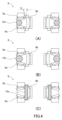
- FIG. 4 is an explanatory diagram showing the shape of the blade receiving metal fitting of the outlet according to the present embodiment
- (A) is C type
- (B) is F type
- (C) is an explanatory view showing the shape of each A type plug. It is explanatory drawing which shows the state which the plug blade of each type of plug was connected to the outlet of this embodiment, (A) shows C type, (B) shows F type, (C) shows A type.
- FIG. 1 the outlet 1 of this embodiment is used in a table tap 2, and in this embodiment, one table tap 2 is provided with three outlets 1. As shown in FIG. 1, the outlet 1 of this embodiment is used in a table tap 2, and in this embodiment, one table tap 2 is provided with three outlets 1. As shown in FIG. 1, the outlet 1 of this embodiment is used in a table tap 2, and in this embodiment, one table tap 2 is provided with three outlets 1. As shown in FIG. 1, the outlet 1 of this embodiment is used in a table tap 2, and in this embodiment, one table tap 2 is provided with three outlets 1. As shown in FIG.
- the table tap 2 is a metal fitting in which an upper case 3 and a lower case 4 made of synthetic resin, three blade receiving covers 5 made of synthetic resin, and three sets of blade receiving metal fittings 6 are connected. It has a unit 7.
- the metal fitting unit 7 includes a base metal fitting 8 connecting three sets of blade receiving metal fittings 6 and a crimp terminal 9 provided at the proximal end portion of the base metal fitting 8 .
- a pair of power cords 10 are crimped and connected to the crimp terminals 9 .
- the crimp terminal 9 is in a state before crimping.
- the blade receiving cover 5 is provided with plug insertion openings 5a into which plug blades of multiple types of plugs can be inserted.
- the plugs of the C type 11c, the F type 11s, and the A type 11a which will be described later, can be inserted.
- the blade receiving metal fitting 6 is formed by a pair of metal fittings having the same shape so that a pair of blades of the plug can be connected.
- the blade receiving metal fitting 6 has a pair of tapered contact pieces 6a that come into contact with the contour of the blade at least two points from the outside and oblique sides when the blade is arranged in the horizontal direction.
- the tapered contact piece 6a is formed of two independent pieces of plate material at the point where it contacts the blade. Specifically, the two taper contact pieces 6a are formed to have a V-shape when viewed from the insertion direction of the blade.
- the blade receiving metal fitting 6 is provided with a pair of plate-like contact pieces 6b which face the contact surfaces of the taper contact pieces 6a with the blade on the inside where the pair of taper contact pieces 6a are arranged.
- the space S between the plate-like contact piece 6b and the tapered contact piece 6a is configured to be narrower than the thickness of the plate-like blade (see FIG. 4A).
- a pair of tapered contact piece 6a and plate-like contact piece 6b are formed by bending a single piece of metal.
- the base end of each contact piece is connected by a connecting portion 6c, and this connecting portion 6c is provided with a fixing hole 6d for fixing to the base metal fitting 8 of the metal fitting unit 7 with a fixing rivet 8a. ing.
- the tapered contact piece 6a and the plate-like contact piece 6b are bent in the same way as the conventional blade receiving fitting so that they come into elastic contact with the blade. .
- FIGS. 3A to 3C can be connected to the outlet 1 of the present embodiment.
- Fig. 3(A) is a plug called C type 11c.
- the blade 12c is formed in the shape of a round bar, the diameter of each round bar is 4.0 mm, and the interval between the shaft centers is 19 mm.
- FIG. 3(B) shows a plug called F type 11s, in which the plug blade 12s is formed in a round bar shape, each round bar having a diameter of 4.8 mm and an axial interval of 19 mm.
- FIG. 3(C) shows a plug called A type 11a, which has a plate-shaped blade 12a and a cross-sectional dimension of 6.3 mm ⁇ 1.5 mm when viewed from the direction of insertion of the blade 12a. is 12.7 mm.
- FIG. 4(A) shows a state in which the C type 11c plug of FIG. 3(A) is connected.
- the blade 12c of the C type 11c is connected to the outlet 1
- the blade 12c is clamped by the tapered contact piece 6a of the blade receiving metal fitting 6 and is electrically connected.
- the F type 11s has a round bar-shaped blade 12s, and the diameter of the round bar is larger than that of the C type 11c.
- the pair of taper contact pieces 6a are deformed in a direction to spread apart from each other, and the blade 12c is clamped as shown in FIG. Contact is conducted.
- the outlet 1 of the present embodiment can connect two types of plug blades 12c and 12s having different diameters.
- the A type 11a has a plate-shaped blade 12a, and the gap between a pair of blades 12a is narrower than the gap between the blade 12c of the C type 11c and the blade 12s of the F type 11s.
- the plate-like contact pieces 6b are curved so as to approach each other inward, and their own resilience pushes the plate-like contact pieces 6b against the blade 12c to establish contact conduction.
- the distance S (see FIG. 4A) between the plate-like contact piece 6b and the tapered contact piece 6a is the thickness of the blade 12a. It is formed to be narrower than the width.
- the outlet 1 of the present embodiment it is possible to connect multiple types of plugs without using an auxiliary spring or the like as in the conventional art. Moreover, it is possible to connect not only the plug blades 12c and 12s in the form of round bars, but also plugs having the plate-shaped blade 12a. In particular, in the outlet 1 of the present embodiment, plugs of C type 11c, F type 11s and A type 11a can be inserted, which is particularly suitable in countries where these plugs are used together.
- the outlet 1 is not limited to this, and may be a wall-mounted type outlet. Further, for example, it is also possible to use the outlet 1 of the present invention as an output of a portable generator or the like.
- the pair of tapered contact pieces 6a are each formed in a V-shape, but the shape is not limited to this, and they may be formed in an L-shape instead of being divided into two pieces.
Landscapes
- Connector Housings Or Holding Contact Members (AREA)
Abstract
【課題】補助ばね等の部材を用いることなく、複数種類のプラグの接続が可能なコンセントを提供する。 【解決手段】コンセント1は、刃受金具6を備えており、刃受金具6は、栓刃の外郭に対して外方且つ斜め側方から少なくとも二箇所で接触する一対のテーパ接触片6aを備える。テーパ接触片6aは、栓刃と接触する箇所において独立した二片の板材で形成され、栓刃の差込方向から見てハの字形状となる。刃受金具6は、一対のテーパ接触片6aが配置されている内側であって、テーパ接触片6aの栓刃との接触面に対して対面する一対の板状接触片6bを備える。板状接触片6bとテーパ接触片6aとの間隔は板状の栓刃の厚さよりも狭い間隔となる。当該構成により、Cタイプ11cの栓刃12c、Fタイプ(SEタイプとも呼ばれる)11sの栓刃12s、及びAタイプ11aの栓刃12aについて、それぞれ接続が可能である。
Description
本発明は、複数種類のプラグを接続可能なユニバーサルタイプのコンセントに関する。
従来より、複数種類のプラグを接続可能なユニバーサルタイプのコンセントが知られている。例えば、特許文献1には、径寸法が異なる丸棒状の栓刃を備えた2種類のプラグのいずれかが接続されるコンセントであって、一方のプラグの栓刃に接触導通する第1の刃受金具と、他方のプラグの栓刃に接触導通する第2の刃受金具を設け、これらの刃受金具の外周に当接して栓刃を挟む方向に付勢する補助ばねを設けたものが開示されている。
当該特許文献1のコンセントは、2種類のプラグの栓刃に対応するために、それぞれの種類の栓刃に接触導通する刃受金具を設けている。また、各刃受金具のみでは接触不良になるおそれがあるため、刃受金具の接触力を高めるための補助ばねを設けている。
上記従来のコンセントは、2種類のプラグが接続可能になるが、3種類以上になると3本の刃受金具が必要となり、スペースの関係で配置が難しく、事実上2種類のプラグへの対応に限られることになる。また、刃受金具には、接触力を高めるための補助ばねが必要となり、部品点数が多くなり、組縦工数も増えるという不都合がある。
本発明は、上記不都合を解消するために、補助ばね等の部材を用いることなく、複数種類のプラグの接続が可能となるコンセントを提供することを目的とする。さらに、本発明は、3種類のプラグを接続することが可能なコンセントを提供することを目的とする。
上記目的を達成するために、本発明のコンセントは、一対の栓刃を備えた複数種類のプラグが接続可能なコンセントであって、前記栓刃が差し込まれた際に接触導通する刃受金具を備え、前記刃受金具は、前記一対の栓刃を水平方向に配置して前記栓刃の差込方向から見た際の前記栓刃の外郭に対して、それぞれの前記栓刃の外方且つ斜め側方から少なくとも二箇所で接触する一対のテーパ接触片を備えていることを特徴とする。
本発明のコンセントによれば、プラグの栓刃に対して外方且つ斜め側方から少なくとも二箇所で接触する一対のテーパ接触片を備えている。具体的には、栓刃の差込方向から見て、刃受金具を「ハの字形状(頂点が離れたV字形状)」又は「L字形状」とする。当該構成により、例えばプラグの栓刃が丸棒状であって、径が異なる2種類のプラグがあった場合、テーパ接触片のテーパ部によって栓刃の径の相違に対応することができる。また、プラグの栓刃間の間隔が異なるプラグであっても、テーパ接触片によって対応することができる。
また、本発明のコンセントにおいて、前記テーパ接触片は、前記栓刃と接触する箇所においてそれぞれ独立した二片の板材で形成されてもよい。このように、テーパ接触片を「ハの字形状」とすることにより、より柔軟にプラグの栓刃形状の相違に対応することができる。
また、本発明のコンセントにおいて、一対の前記テーパ接触片の内側であって、前記テーパ接触片の前記栓刃との接触面に対して対面する一対の板状接触片を備えていてもよい。当該構成によれば、テーパ接触片に当接するプラグよりも間隔の狭いプラグであっても、板状接触片により接触導通することができる。これにより、径の異なる丸棒状のプラグのみならず、丸棒状のプラグよりも間隔の狭い板状のプラグについても接続することができる。
また、本発明のコンセントにおいて、板状の栓刃を接続可能とするときは、前記板状接触片と一対の前記テーパ接触片との間隔を、前記板状の栓刃の厚さよりも狭くすることが好ましい。当該構成により、板状の栓刃を、板状接触片とテーパ接触片との間に挟持することができるので、コンセントとプラグの接続安定性が向上する。
本発明のコンセントにおいて、具体的には、接続可能な前記プラグが、直径が4.8mmの丸棒状の栓刃が19mmの間隔で設けられたFタイプと、直径が4.0mmの丸棒状の栓刃が19mmの間隔で設けられたCタイプと、差込方向から見た断面寸法が6.3mm×1.5mmの板状の栓刃が12.7mmの間隔で設けられたAタイプであり、前記Fタイプと前記Cタイプのプラグが接続された際には前記テーパ接触片により栓刃と接触し、前記Aタイプのプラグが接続された際には前記板状接触片により栓刃と接触することができる。なお、Fタイプは、SEタイプと呼ばれることがある。
本発明によれば、補助ばね等の部材を用いることなく、複数種類のプラグの接続が可能となるコンセントを提供することができる。さらに、本発明は、3種類のプラグを接続することが可能なコンセントを提供することができる。
次に、図1乃至図3を参照して、本発明の実施形態の一例であるコンセントについて説明する。本実施形態のコンセント1は、図1に示すように、テーブルタップ2に用いられており、本実施形態では、1個のテーブルタップ2に3個のコンセント1が設けられている。
テーブルタップ2は、図1に示すように、合成樹脂製の上ケース3及び下ケース4と、合成樹脂製の3個の刃受カバー5と、3組の刃受金具6が連結された金具ユニット7を備えている。金具ユニット7は、3組の刃受金具6を連結するベース金具8と、ベース金具8の基端部に設けられた圧着端子9とを備えている。圧着端子9には、一対の電源コード10が圧着されて接続される。図1においては、圧着端子9は圧着前の状態となっている。
刃受カバー5には、複数のタイプのプラグの栓刃が挿入可能なプラグ挿入口5aを備えている。本実施形態では、後述するCタイプ11c、Fタイプ11s、及びAタイプ11aのプラグが挿入可能な形状となっている。
次に、図2を参照して、本実施形態のコンセント1の刃受金具6の形状について説明する。刃受金具6は、プラグの一対の栓刃を接続可能なように、同一形状の一対の金具により形成される。刃受金具6は、栓刃を水平方向に配置した際に、栓刃の外郭に対して外方且つ斜め側方から少なくとも二箇所で接触する一対のテーパ接触片6aを備えている。
テーパ接触片6aは、栓刃と接触する箇所において独立した二片の板材で形成されている。具体的には、この二片のテーパ接触片6aは、栓刃の差込方向から見てハの字形状となるように形成されている。
また、刃受金具6は、一対のテーパ接触片6aが配置されている内側であって、テーパ接触片6aの栓刃との接触面に対して対面する一対の板状接触片6bを備えている。この板状接触片6bとテーパ接触片6aとの間隔Sは、板状の栓刃の厚さよりも狭い間隔となるように構成されている(図4(A)参照)。
また、図2に示すように、本実施形態の刃受金具6は、一対のテーパ接触片6a及び板状接触片6bが1枚の金属片を曲げ加工することにより形成されている。図2において、各接触片の基端部は連結部6cにより連結されており、この連結部6cには金具ユニット7のベース金具8に固定リベット8aで固定するための固定用孔6dが設けられている。
また、テーパ接触片6a及び板状接触片6bは、図2に示すように、栓刃に対して弾性を伴って接触するように、従来の刃受金具と同様の曲げ加工が行われている。
次に、本実施形態のコンセント1を有するテーブルタップ2に接続されるプラグについて、図3を参照して説明する。本実施形態のコンセント1は、図3(A)~(C)の各プラグが接続可能となっている。
図3(A)は、Cタイプ11cと呼ばれるプラグである。このCタイプ11cは、栓刃12cが丸棒状に形成されており、各丸棒の直径は4.0mmであり、その軸芯の間隔は19mmとなっている。図3(B)は、Fタイプ11sと呼ばれるプラグであり、栓刃12sが丸棒状に形成され、各丸棒の直径は4.8mmであり、その軸芯の間隔は19mmとなっている。図3(C)は、Aタイプ11aと呼ばれるプラグであり、栓刃12aが板状であり、栓刃12aを差込方向から見た断面寸法が6.3mm×1.5mmであり、その間隔が12.7mmとなっている。
次に、図4を参照して、本実施形態のコンセント1に各プラグの栓刃12c、12s、及び12aが接続された状態について説明する。図4(A)は、図3(A)のCタイプ11cのプラグが接続された状態を示している。図4(A)に示すように、Cタイプ11cの栓刃12cが、コンセント1に接続されると、刃受金具6のテーパ接触片6aによって栓刃12cが挟持されて接触導通される。
次に図4(B)を参照して、Fタイプ11sのプラグがコンセント1に接続された場合の刃受金具6の状態について説明する。Fタイプ11sは、栓刃12sが丸棒状であり、Cタイプ11cに比べて丸棒の直径が大径となっている。当該Fタイプ11sの栓刃12sが刃受金具6に接続されると、図4(B)に示すように、一対のテーパ接触片6aが互いに広がる方向に変形し、栓刃12cが挟持されて接触導通される。このように、本実施形態のコンセント1は、径の異なる二種類の栓刃12c及び12sを接続させることができる。
次に、図4(C)を参照して、Aタイプ11aのプラグがコンセント1に接続された場合の刃受金具6の状態について説明する。Aタイプ11aは、栓刃12aが板状であり、一対の栓刃12aの間隔が、Cタイプ11cの栓刃12cやFタイプ11sの栓刃12sの間隔よりも狭くなっている。
本実施形態のコンセント1においては、図4(C)における一対の板状接触片6b同士の間隔が、Aタイプ11aの栓刃12aの間隔よりも若干広くなっており、栓刃12aが差し込まれた際には、板状接触片6bが互いに内側に近づくように湾曲し、自身の弾性により栓刃12cに板状接触片6bを押しつけるようにして接触導通される。
また、本実施形態のコンセント1では、栓刃12aが差し込まれていない状態において、板状接触片6bとテーパ接触片6aとの間隔S(図4(A)参照)が、栓刃12aの厚さよりも狭くなるように形成されている。これにより、コンセント1にAタイプ11aのプラグの栓刃12aが差し込まれたときは、図4(C)に示すように、板状接触片6bとテーパ接触片6aの側辺との間に栓刃12aが挟持される。従って、刃受金具6と栓刃12aとの接触圧力が高くなり、確実に導通が行われる。
以上のように、本実施形態のコンセント1によれば、従来のように補助ばね等を用いることなく、複数種類のプラグを接続することが可能となる。また、丸棒状の栓刃12c、12sのみならず、板状の栓刃12aを有するプラグも接続することが可能となる。特に、本実施形態のコンセント1においては、Cタイプ11c、Fタイプ11s、及びAタイプ11aのプラグが挿入可能であり、これらのプラグが併用される国において特に好適となる。
なお、上記実施形態においては、コンセント1をテーブルタップ2に適用した例について説明したが、これに限らず、壁面に取り付けるタイプのコンセントとしてもよい。また、例えば、ポータブル発電機等のアウトプットとして、本発明のコンセント1を用いることも可能である。また、上記実施形態においては、一対のテーパ接触片6aは、それぞれハの字状に形成しているが、これに限らず、2片に分けずにL字形状としてもよい。
また、上記実施形態においては、Cタイプ11c、Fタイプ11s、及びAタイプ11aのプラグが挿入可能な例について説明したが、これに限らず、刃受金具の形状を変更することにより、他のタイプ(BタイプやOタイプ等)についても適用が可能である。
1…コンセント
2…テーブルタップ
6…刃受金具
6a…テーパ接触片
6b…板状接触片
10…電源コード
11a…Aタイププラグ
11c…Cタイププラグ
11s…Fタイププラグ
12a~12c…栓刃
2…テーブルタップ
6…刃受金具
6a…テーパ接触片
6b…板状接触片
10…電源コード
11a…Aタイププラグ
11c…Cタイププラグ
11s…Fタイププラグ
12a~12c…栓刃
Claims (5)
- 一対の栓刃を備えた複数種類のプラグが接続可能なコンセントであって、
前記栓刃が差し込まれた際に接触導通する刃受金具を備え、
前記刃受金具は、前記一対の栓刃を水平方向に配置して前記栓刃の差込方向から見た際の前記栓刃の外郭に対して、それぞれの前記栓刃の外方且つ斜め側方から少なくとも二箇所で接触する一対のテーパ接触片を備えていることを特徴とするコンセント。 - 請求項1に記載のコンセントであって、
前記テーパ接触片は、前記栓刃と接触する箇所においてそれぞれ独立した二片の板材で形成されていることを特徴とするコンセント。 - 請求項1又は2に記載のコンセントであって、
一対の前記テーパ接触片の内側であって、前記テーパ接触片の前記栓刃との接触面に対して対面する一対の板状接触片を備えていることを特徴とするコンセント。 - 請求項3に記載のコンセントであって、
板状の栓刃を接続可能であり、
前記板状接触片と一対の前記テーパ接触片との間隔を、前記板状の栓刃の厚さよりも狭くしたことを特徴とするコンセント。 - 請求項3又は4に記載のコンセントであって、
接続可能な前記プラグが、直径が4.8mmの丸棒状の栓刃が19mmの間隔で設けられたFタイプと、直径が4.0mmの丸棒状の栓刃が19mmの間隔で設けられたCタイプと、差込方向から見た断面寸法が6.3mm×1.5mmの板状の栓刃が12.7mmの間隔で設けられたAタイプであり、
前記Fタイプと前記Cタイプのプラグが接続された際には前記テーパ接触片により栓刃と接触し、
前記Aタイプのプラグが接続された際には前記板状接触片により栓刃と接触することを特徴とするコンセント。
Priority Applications (1)
| Application Number | Priority Date | Filing Date | Title |
|---|---|---|---|
| PCT/JP2021/047452 WO2023119457A1 (ja) | 2021-12-21 | 2021-12-21 | ユニバーサルコンセント |
Applications Claiming Priority (1)
| Application Number | Priority Date | Filing Date | Title |
|---|---|---|---|
| PCT/JP2021/047452 WO2023119457A1 (ja) | 2021-12-21 | 2021-12-21 | ユニバーサルコンセント |
Publications (1)
| Publication Number | Publication Date |
|---|---|
| WO2023119457A1 true WO2023119457A1 (ja) | 2023-06-29 |
Family
ID=86901685
Family Applications (1)
| Application Number | Title | Priority Date | Filing Date |
|---|---|---|---|
| PCT/JP2021/047452 WO2023119457A1 (ja) | 2021-12-21 | 2021-12-21 | ユニバーサルコンセント |
Country Status (1)
| Country | Link |
|---|---|
| WO (1) | WO2023119457A1 (ja) |
Citations (7)
| Publication number | Priority date | Publication date | Assignee | Title |
|---|---|---|---|---|
| JPS5036090U (ja) * | 1973-07-30 | 1975-04-16 | ||
| JPH0269476U (ja) * | 1988-11-15 | 1990-05-25 | ||
| JP3075169U (ja) * | 2000-07-26 | 2001-02-09 | 秋山 李 | 簡易マルチタイプ雄雌型コネクタ |
| JP2004335352A (ja) * | 2003-05-09 | 2004-11-25 | Izutsu Seisakusho:Kk | アダプタープラグ |
| JP2007087897A (ja) * | 2005-09-26 | 2007-04-05 | Kitakyushu Foundation For The Advancement Of Industry Science & Technology | ユニバーサルアダプタ |
| JP2009176699A (ja) * | 2007-12-27 | 2009-08-06 | Churi:Kk | プラグ変換アダプタ及びプラグ変換アダプタ器具 |
| JP3176592U (ja) * | 2012-05-14 | 2012-06-28 | 維熹科技股▲ふん▼有限公司 | テーブルタップ |
-
2021
- 2021-12-21 WO PCT/JP2021/047452 patent/WO2023119457A1/ja unknown
Patent Citations (7)
| Publication number | Priority date | Publication date | Assignee | Title |
|---|---|---|---|---|
| JPS5036090U (ja) * | 1973-07-30 | 1975-04-16 | ||
| JPH0269476U (ja) * | 1988-11-15 | 1990-05-25 | ||
| JP3075169U (ja) * | 2000-07-26 | 2001-02-09 | 秋山 李 | 簡易マルチタイプ雄雌型コネクタ |
| JP2004335352A (ja) * | 2003-05-09 | 2004-11-25 | Izutsu Seisakusho:Kk | アダプタープラグ |
| JP2007087897A (ja) * | 2005-09-26 | 2007-04-05 | Kitakyushu Foundation For The Advancement Of Industry Science & Technology | ユニバーサルアダプタ |
| JP2009176699A (ja) * | 2007-12-27 | 2009-08-06 | Churi:Kk | プラグ変換アダプタ及びプラグ変換アダプタ器具 |
| JP3176592U (ja) * | 2012-05-14 | 2012-06-28 | 維熹科技股▲ふん▼有限公司 | テーブルタップ |
Similar Documents
| Publication | Publication Date | Title |
|---|---|---|
| JPH0737635A (ja) | 電気接続端子 | |
| US5913694A (en) | Connector assembly | |
| CN107342472B (zh) | 用于插槽式接触的套筒、使用该套筒的连接件以及制造方法 | |
| WO2021090698A1 (ja) | コネクタ | |
| US6905371B2 (en) | Terminal and connector using same | |
| US5413509A (en) | Multi-wire locking system | |
| US8360812B2 (en) | Tab-form terminal with reduced material and manufacturing cost | |
| JP2013187163A (ja) | コネクタ端子用接触ばね及び雌端子、雄端子、コネクタ | |
| JP2014035959A (ja) | 多接点型雌端子 | |
| WO2018163814A1 (ja) | 雄端子 | |
| JP2005294217A (ja) | 圧接型コンタクトおよびそれを用いた電気コネクタ | |
| WO2023119457A1 (ja) | ユニバーサルコンセント | |
| JP2004319338A (ja) | プレスフィット端子及び基板用コネクタ | |
| JP2015207353A (ja) | 電線用コネクタ | |
| JP2014035875A (ja) | 雌端子 | |
| JP7232416B2 (ja) | 雌端子 | |
| CN218940140U (zh) | 密封件、连接器壳体组件和连接器 | |
| US6149453A (en) | IDC socket strain relief cap rework tool | |
| CN215816532U (zh) | 一种矩形插头 | |
| JP2002025673A (ja) | 接続端子 | |
| JP5173777B2 (ja) | オス端子の構造 | |
| US7909667B1 (en) | Crimp contacts and electrical connector assemblies including the same | |
| JPH03127470A (ja) | 電気コネクター | |
| JP2000021485A (ja) | 接触子及びこの接触子を備えたコネクタ装置 | |
| KR20220112837A (ko) | 소켓 콘택 |
Legal Events
| Date | Code | Title | Description |
|---|---|---|---|
| 121 | Ep: the epo has been informed by wipo that ep was designated in this application |
Ref document number: 21968894 Country of ref document: EP Kind code of ref document: A1 |