WO2023119457A1 - ユニバーサルコンセント - Google Patents
ユニバーサルコンセント Download PDFInfo
- Publication number
- WO2023119457A1 WO2023119457A1 PCT/JP2021/047452 JP2021047452W WO2023119457A1 WO 2023119457 A1 WO2023119457 A1 WO 2023119457A1 JP 2021047452 W JP2021047452 W JP 2021047452W WO 2023119457 A1 WO2023119457 A1 WO 2023119457A1
- Authority
- WO
- WIPO (PCT)
- Prior art keywords
- blade
- type
- plug
- plate
- pair
- Prior art date
- Legal status (The legal status is an assumption and is not a legal conclusion. Google has not performed a legal analysis and makes no representation as to the accuracy of the status listed.)
- Ceased
Links
Images


Classifications
-
- H—ELECTRICITY
- H01—ELECTRIC ELEMENTS
- H01R—ELECTRICALLY-CONDUCTIVE CONNECTIONS; STRUCTURAL ASSOCIATIONS OF A PLURALITY OF MUTUALLY-INSULATED ELECTRICAL CONNECTING ELEMENTS; COUPLING DEVICES; CURRENT COLLECTORS
- H01R25/00—Coupling parts adapted for simultaneous co-operation with two or more identical counterparts, e.g. for distributing energy to two or more circuits
Definitions
- the present invention relates to a universal type outlet to which multiple types of plugs can be connected.
- Patent Document 1 discloses an outlet to which one of two types of plugs having round-bar-shaped plug blades with different diameters is connected, and a first blade that contacts and conducts with the plug blade of one of the plugs.
- a plug is provided with a receiving metal fitting and a second blade receiving metal fitting that contacts and conducts with the blade of the other plug, and is provided with an auxiliary spring that abuts against the outer periphery of these blade receiving metal fittings and urges the blade in a direction to pinch it. disclosed.
- Patent Document 1 In order to accommodate two types of plug blades, the outlet of Patent Document 1 is provided with blade receiving metal fittings that contact and conduct the plug blades of each type. In addition, since there is a risk of poor contact with each blade receiving metal fitting alone, an auxiliary spring is provided to increase the contact force of the blade receiving metal fitting.
- the above-mentioned conventional outlet can connect two types of plugs, but if there are more than three types of plugs, three blade receiving metal fittings are required. will be limited.
- the blade receiving metal requires an auxiliary spring for increasing the contact force, which increases the number of parts and man-hours required for assembly.
- An object of the present invention is to provide an outlet that allows connection of a plurality of types of plugs without using a member such as an auxiliary spring, in order to eliminate the above inconvenience.
- a further object of the present invention is to provide an outlet to which three types of plugs can be connected.
- the present invention provides an electrical outlet which is provided with a pair of blades and to which a plurality of types of plugs can be connected.
- the blade receiving metal fitting is positioned outwardly and outwardly of each of the blades with respect to the outline of the blades when viewed from the insertion direction of the blades with the pair of blades arranged in the horizontal direction. It is characterized by having a pair of tapered contact pieces that contact at least two points from oblique sides.
- the socket of the present invention it is provided with a pair of tapered contact pieces that come into contact with the plug blade of the plug at least two points from the outside and oblique sides.
- the blade receiving fitting is made to have a "V-shape (a V-shape with a distant vertex)" or an "L-shape".
- the tapered contact piece may be formed of two pieces of independent plate material at a portion that contacts the blade.
- the socket outlet of the present invention may include a pair of plate-like contact pieces that are inside the pair of tapered contact pieces and face the contact surfaces of the tapered contact pieces with the blade.
- the plate-shaped contact piece enables contact conduction even with plugs that are closer to each other than the plug that abuts on the tapered contact piece.
- the distance between the plate-shaped contact piece and the pair of tapered contact pieces is made narrower than the thickness of the plate-shaped blade. is preferred. With this configuration, the plate-like plug blade can be sandwiched between the plate-like contact piece and the tapered contact piece, thereby improving connection stability between the receptacle and the plug.
- the connectable plug is an F type in which round bar-shaped plug blades with a diameter of 4.8 mm are provided at intervals of 19 mm, and a round bar-shaped plug with a diameter of 4.0 mm.
- the C type has blades spaced 19 mm apart
- the A type has plate-shaped blades with a cross-sectional dimension of 6.3 mm x 1.5 mm when viewed from the direction of insertion, spaced 12.7 mm apart.
- the present invention it is possible to provide an outlet that allows connection of multiple types of plugs without using a member such as an auxiliary spring. Furthermore, the present invention can provide an outlet capable of connecting three types of plugs.
- FIG. 1 is an exploded perspective view of a power strip to which an outlet is applied, which is an example of an embodiment of the present invention
- FIG. 4 is an explanatory diagram showing the shape of the blade receiving metal fitting of the outlet according to the present embodiment
- (A) is C type
- (B) is F type
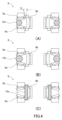
- (C) is an explanatory view showing the shape of each A type plug. It is explanatory drawing which shows the state which the plug blade of each type of plug was connected to the outlet of this embodiment, (A) shows C type, (B) shows F type, (C) shows A type.
- FIG. 1 the outlet 1 of this embodiment is used in a table tap 2, and in this embodiment, one table tap 2 is provided with three outlets 1. As shown in FIG. 1, the outlet 1 of this embodiment is used in a table tap 2, and in this embodiment, one table tap 2 is provided with three outlets 1. As shown in FIG. 1, the outlet 1 of this embodiment is used in a table tap 2, and in this embodiment, one table tap 2 is provided with three outlets 1. As shown in FIG. 1, the outlet 1 of this embodiment is used in a table tap 2, and in this embodiment, one table tap 2 is provided with three outlets 1. As shown in FIG.
- the table tap 2 is a metal fitting in which an upper case 3 and a lower case 4 made of synthetic resin, three blade receiving covers 5 made of synthetic resin, and three sets of blade receiving metal fittings 6 are connected. It has a unit 7.
- the metal fitting unit 7 includes a base metal fitting 8 connecting three sets of blade receiving metal fittings 6 and a crimp terminal 9 provided at the proximal end portion of the base metal fitting 8 .
- a pair of power cords 10 are crimped and connected to the crimp terminals 9 .
- the crimp terminal 9 is in a state before crimping.
- the blade receiving cover 5 is provided with plug insertion openings 5a into which plug blades of multiple types of plugs can be inserted.
- the plugs of the C type 11c, the F type 11s, and the A type 11a which will be described later, can be inserted.
- the blade receiving metal fitting 6 is formed by a pair of metal fittings having the same shape so that a pair of blades of the plug can be connected.
- the blade receiving metal fitting 6 has a pair of tapered contact pieces 6a that come into contact with the contour of the blade at least two points from the outside and oblique sides when the blade is arranged in the horizontal direction.
- the tapered contact piece 6a is formed of two independent pieces of plate material at the point where it contacts the blade. Specifically, the two taper contact pieces 6a are formed to have a V-shape when viewed from the insertion direction of the blade.
- the blade receiving metal fitting 6 is provided with a pair of plate-like contact pieces 6b which face the contact surfaces of the taper contact pieces 6a with the blade on the inside where the pair of taper contact pieces 6a are arranged.
- the space S between the plate-like contact piece 6b and the tapered contact piece 6a is configured to be narrower than the thickness of the plate-like blade (see FIG. 4A).
- a pair of tapered contact piece 6a and plate-like contact piece 6b are formed by bending a single piece of metal.
- the base end of each contact piece is connected by a connecting portion 6c, and this connecting portion 6c is provided with a fixing hole 6d for fixing to the base metal fitting 8 of the metal fitting unit 7 with a fixing rivet 8a. ing.
- the tapered contact piece 6a and the plate-like contact piece 6b are bent in the same way as the conventional blade receiving fitting so that they come into elastic contact with the blade. .
- FIGS. 3A to 3C can be connected to the outlet 1 of the present embodiment.
- Fig. 3(A) is a plug called C type 11c.
- the blade 12c is formed in the shape of a round bar, the diameter of each round bar is 4.0 mm, and the interval between the shaft centers is 19 mm.
- FIG. 3(B) shows a plug called F type 11s, in which the plug blade 12s is formed in a round bar shape, each round bar having a diameter of 4.8 mm and an axial interval of 19 mm.
- FIG. 3(C) shows a plug called A type 11a, which has a plate-shaped blade 12a and a cross-sectional dimension of 6.3 mm ⁇ 1.5 mm when viewed from the direction of insertion of the blade 12a. is 12.7 mm.
- FIG. 4(A) shows a state in which the C type 11c plug of FIG. 3(A) is connected.
- the blade 12c of the C type 11c is connected to the outlet 1
- the blade 12c is clamped by the tapered contact piece 6a of the blade receiving metal fitting 6 and is electrically connected.
- the F type 11s has a round bar-shaped blade 12s, and the diameter of the round bar is larger than that of the C type 11c.
- the pair of taper contact pieces 6a are deformed in a direction to spread apart from each other, and the blade 12c is clamped as shown in FIG. Contact is conducted.
- the outlet 1 of the present embodiment can connect two types of plug blades 12c and 12s having different diameters.
- the A type 11a has a plate-shaped blade 12a, and the gap between a pair of blades 12a is narrower than the gap between the blade 12c of the C type 11c and the blade 12s of the F type 11s.
- the plate-like contact pieces 6b are curved so as to approach each other inward, and their own resilience pushes the plate-like contact pieces 6b against the blade 12c to establish contact conduction.
- the distance S (see FIG. 4A) between the plate-like contact piece 6b and the tapered contact piece 6a is the thickness of the blade 12a. It is formed to be narrower than the width.
- the outlet 1 of the present embodiment it is possible to connect multiple types of plugs without using an auxiliary spring or the like as in the conventional art. Moreover, it is possible to connect not only the plug blades 12c and 12s in the form of round bars, but also plugs having the plate-shaped blade 12a. In particular, in the outlet 1 of the present embodiment, plugs of C type 11c, F type 11s and A type 11a can be inserted, which is particularly suitable in countries where these plugs are used together.
- the outlet 1 is not limited to this, and may be a wall-mounted type outlet. Further, for example, it is also possible to use the outlet 1 of the present invention as an output of a portable generator or the like.
- the pair of tapered contact pieces 6a are each formed in a V-shape, but the shape is not limited to this, and they may be formed in an L-shape instead of being divided into two pieces.
Landscapes
- Connector Housings Or Holding Contact Members (AREA)
Priority Applications (2)
| Application Number | Priority Date | Filing Date | Title |
|---|---|---|---|
| PCT/JP2021/047452 WO2023119457A1 (ja) | 2021-12-21 | 2021-12-21 | ユニバーサルコンセント |
| JP2023568857A JPWO2023119457A1 (https=) | 2021-12-21 | 2021-12-21 |
Applications Claiming Priority (1)
| Application Number | Priority Date | Filing Date | Title |
|---|---|---|---|
| PCT/JP2021/047452 WO2023119457A1 (ja) | 2021-12-21 | 2021-12-21 | ユニバーサルコンセント |
Publications (1)
| Publication Number | Publication Date |
|---|---|
| WO2023119457A1 true WO2023119457A1 (ja) | 2023-06-29 |
Family
ID=86901685
Family Applications (1)
| Application Number | Title | Priority Date | Filing Date |
|---|---|---|---|
| PCT/JP2021/047452 Ceased WO2023119457A1 (ja) | 2021-12-21 | 2021-12-21 | ユニバーサルコンセント |
Country Status (2)
| Country | Link |
|---|---|
| JP (1) | JPWO2023119457A1 (https=) |
| WO (1) | WO2023119457A1 (https=) |
Citations (7)
| Publication number | Priority date | Publication date | Assignee | Title |
|---|---|---|---|---|
| JPS5036090U (https=) * | 1973-07-30 | 1975-04-16 | ||
| JPH0269476U (https=) * | 1988-11-15 | 1990-05-25 | ||
| JP3075169U (ja) * | 2000-07-26 | 2001-02-09 | 秋山 李 | 簡易マルチタイプ雄雌型コネクタ |
| JP2004335352A (ja) * | 2003-05-09 | 2004-11-25 | Izutsu Seisakusho:Kk | アダプタープラグ |
| JP2007087897A (ja) * | 2005-09-26 | 2007-04-05 | Kitakyushu Foundation For The Advancement Of Industry Science & Technology | ユニバーサルアダプタ |
| JP2009176699A (ja) * | 2007-12-27 | 2009-08-06 | Churi:Kk | プラグ変換アダプタ及びプラグ変換アダプタ器具 |
| JP3176592U (ja) * | 2012-05-14 | 2012-06-28 | 維熹科技股▲ふん▼有限公司 | テーブルタップ |
-
2021
- 2021-12-21 JP JP2023568857A patent/JPWO2023119457A1/ja active Pending
- 2021-12-21 WO PCT/JP2021/047452 patent/WO2023119457A1/ja not_active Ceased
Patent Citations (7)
| Publication number | Priority date | Publication date | Assignee | Title |
|---|---|---|---|---|
| JPS5036090U (https=) * | 1973-07-30 | 1975-04-16 | ||
| JPH0269476U (https=) * | 1988-11-15 | 1990-05-25 | ||
| JP3075169U (ja) * | 2000-07-26 | 2001-02-09 | 秋山 李 | 簡易マルチタイプ雄雌型コネクタ |
| JP2004335352A (ja) * | 2003-05-09 | 2004-11-25 | Izutsu Seisakusho:Kk | アダプタープラグ |
| JP2007087897A (ja) * | 2005-09-26 | 2007-04-05 | Kitakyushu Foundation For The Advancement Of Industry Science & Technology | ユニバーサルアダプタ |
| JP2009176699A (ja) * | 2007-12-27 | 2009-08-06 | Churi:Kk | プラグ変換アダプタ及びプラグ変換アダプタ器具 |
| JP3176592U (ja) * | 2012-05-14 | 2012-06-28 | 維熹科技股▲ふん▼有限公司 | テーブルタップ |
Also Published As
| Publication number | Publication date |
|---|---|
| JPWO2023119457A1 (https=) | 2023-06-29 |
Similar Documents
| Publication | Publication Date | Title |
|---|---|---|
| CN104521070B (zh) | 多件式插座触头组件 | |
| JP5053759B2 (ja) | ソケット端子 | |
| US5913694A (en) | Connector assembly | |
| JP7232416B2 (ja) | 雌端子 | |
| CN106972301B (zh) | 用于电力连接器的具有顺应销的电力端子 | |
| CN107342472B (zh) | 用于插槽式接触的套筒、使用该套筒的连接件以及制造方法 | |
| WO2021090698A1 (ja) | コネクタ | |
| US10847914B2 (en) | Male terminal | |
| US8360812B2 (en) | Tab-form terminal with reduced material and manufacturing cost | |
| JP2003203726A (ja) | 電気コネクタの端子及びそれを用いた電気コネクタ | |
| WO2023119457A1 (ja) | ユニバーサルコンセント | |
| JPWO2019044905A1 (ja) | 同軸コネクタ及び同軸ケーブル付き同軸コネクタ | |
| JP2004319338A (ja) | プレスフィット端子及び基板用コネクタ | |
| US10439335B2 (en) | Electrical plug connector with an electrical contact for grounding a housing | |
| JP2015207353A (ja) | 電線用コネクタ | |
| JP6681655B2 (ja) | 同軸コネクタ | |
| JP2002025673A (ja) | 接続端子 | |
| KR102694679B1 (ko) | 소켓 콘택 | |
| JP5173777B2 (ja) | オス端子の構造 | |
| JP2000021485A (ja) | 接触子及びこの接触子を備えたコネクタ装置 | |
| JPH03127470A (ja) | 電気コネクター | |
| KR20250178243A (ko) | 플로팅 커넥터 | |
| JP2000123819A (ja) | 電 池 | |
| KR200294134Y1 (ko) | 커넥터 접속단자 | |
| JP3920255B2 (ja) | 同軸コネクタ |
Legal Events
| Date | Code | Title | Description |
|---|---|---|---|
| 121 | Ep: the epo has been informed by wipo that ep was designated in this application |
Ref document number: 21968894 Country of ref document: EP Kind code of ref document: A1 |
|
| WWE | Wipo information: entry into national phase |
Ref document number: 2023568857 Country of ref document: JP |
|
| NENP | Non-entry into the national phase |
Ref country code: DE |
|
| 122 | Ep: pct application non-entry in european phase |
Ref document number: 21968894 Country of ref document: EP Kind code of ref document: A1 |