WO2023119435A1 - アシスト装置 - Google Patents
アシスト装置 Download PDFInfo
- Publication number
- WO2023119435A1 WO2023119435A1 PCT/JP2021/047385 JP2021047385W WO2023119435A1 WO 2023119435 A1 WO2023119435 A1 WO 2023119435A1 JP 2021047385 W JP2021047385 W JP 2021047385W WO 2023119435 A1 WO2023119435 A1 WO 2023119435A1
- Authority
- WO
- WIPO (PCT)
- Prior art keywords
- assist
- handle
- gripped
- force
- portions
- Prior art date
- Legal status (The legal status is an assumption and is not a legal conclusion. Google has not performed a legal analysis and makes no representation as to the accuracy of the status listed.)
- Ceased
Links
Images




Classifications
-
- B—PERFORMING OPERATIONS; TRANSPORTING
- B62—LAND VEHICLES FOR TRAVELLING OTHERWISE THAN ON RAILS
- B62D—MOTOR VEHICLES; TRAILERS
- B62D53/00—Tractor-trailer combinations; Road trains
Definitions
- the present invention relates to an assist device.
- Patent Document 1 discloses that an operating device attached to one end of a bed and a traveling carriage attached to the other end of the bed are provided, and the traveling carriage cannot be moved unless the operating device is operated with both hands. is described.
- the assist force is applied on the condition that both hands are operated, which is advantageous for improving the stability during assist.
- the assist force is applied on the condition that both hands are operated, which is advantageous for improving the stability during assist.
- An assist device for applying an assisting force for movement to a given article when moving the given article, comprising: a driving source for generating the assisting force; a drive wheel driven by the assisting force; and connected to the given article. and a handle having left and right grip portions positioned on the left and right end sides, and an external force acting on the left and right grip portions when it is detected that the left and right grip portions are gripped. and an assist control unit for controlling the assist force according to the condition, the handle has a central gripping portion between the left and right gripping portions, and the assist control portion has a central gripping portion between the left and right gripping portions. and, when it is detected that the central gripping portion is gripped, the assisting force is controlled according to an external force acting on the central gripping portion.
- User convenience is improved because it is equipped with a function that assists with two-handed operation as well as a function that assists with one-handed operation.
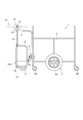
- FIG. 1 is a diagram showing an assist device according to an embodiment of the present invention together with a predetermined article.
- FIG. 2 is a side view of the assist device together with the push cart.
- FIG. 3 is a view showing the assist device together with the push cart from above.
- FIG. 4 is a diagram showing the internal structure of the handle portion and the device main body.
- FIG. 5 is a side cross-sectional view of the left-right center of the handle portion.
- FIG. 6 is a block diagram showing the electrical configuration of the assist device.
- FIG. 7 is a flow chart showing the basic operation of the assist device.
- FIG. 8 is a diagram showing the rotary operator together with its peripheral configuration.
- FIG. 9 is a diagram illustrating a display mode of the display unit.
- FIG. 1 is a diagram showing an assist device according to an embodiment of the present invention together with a predetermined article.
- the predetermined article of the present embodiment is a large pushcart 1, which is also called a large cart, a pushcart, a stroller, and a stroller cart.
- This push cart 1 can carry a plurality of infants, and is used, for example, when a user such as a nursery teacher moves the infants from a nursery facility to an arbitrary place such as a park.
- a pushcart 1 has a storage portion 2 for storing infants, baggage, etc., wheels 3 provided in the storage portion 2, and a handle 5 attached to a frame-shaped frame 4 provided in the storage portion 2. ing.
- the wheels 3 have a pair of left and right large wheels 3A that cannot be steered, and a plurality of casters 3B positioned around the large wheels 3A, and are configured to be able to move forward, backward, and turn left and right.
- An assist device 10 is connected to the frame 4 of the push cart 1 via a holder 7 .
- the holder 7 is a member that can be attached to and detached from the frame 4, and is attached to the frame 4 positioned at the rear of the push cart 1 when the assist device 10 is used.
- the holder 7 has a holder main body 7A projecting rearward when attached to the push cart 1, and the assist device 10 can be attached to and detached from the holder main body 7A.
- the assist device 10 is a device that provides an assist force for movement to the push cart 1 when moving the push cart 1 .
- the push cart 1 can also be said to be a moving object whose movement is assisted by the assist device 10 .
- the handle 5 of the push cart 1 can be said to be a handle to be moved, and will be referred to as a "cart-side handle 5" in the following description.
- the assist device 10 includes a device body 12 having a drive wheel 11 , a handle shaft 13 extending upward from the device body 12 , and a handle portion 14 attached to the upper portion of the handle shaft 13 .
- the handle portion 14 is a portion that functions as an operation device operated by the user and as an output device that outputs information to the user.
- the handle portion 14 has a handle 15 extending left and right, a display unit 16 supported below the handle 15, and an operation portion 26 (FIG. 6) operated by a user.
- FIG. 2 is a side view of the assist device 10 together with the push cart 1.
- FIG. 3 is a diagram showing the assist device 10 together with the push cart 1 from above.
- the handle shaft 13 is rotatably supported by the device main body 12 and rotates left and right integrally with the handle portion 14 .
- Reference numeral C1 in FIG. 2 denotes the central axis of the handle shaft 13, and is appropriately referred to as "handle axis C1".
- the handle shaft 13 extends upward from the rear portion of the device main body 12 and supports the handle 15 above the cart-side handle 5 . Since the handle 15 is supported above the cart-side handle 5 and at a position spaced rearward from the housing portion 2, the handle 15 does not come into contact with the cart-side handle 5 even when the handle 15 is rotated. can easily steer the steering wheel 15 left and right.
- the display unit 16 is also supported above the cart-side handle 5 and at a position spaced rearward from the housing portion 2 . Therefore, the display unit 16 does not come into contact with the push cart 1 even when the steering wheel 15 is steered left and right.
- the positions of the handle 15, the display unit 16, and the like may be appropriately changed as long as they do not come into contact with the push cart 1.
- FIG. 4 is a diagram showing the internal structure of the handle portion 14 and the apparatus body 12.
- the handle 15 has left and right grip portions 15L and 15R positioned at the left and right end portions, and a center grip portion 15C positioned between the left and right grip portions 15L and 15R.
- the left and right grip portions 15L and 15R are handle portions suitable for the user to grip with both hands.
- the central grip portion 15C is a handle portion that can be gripped by the user with one hand. Between the left and right gripping portions 15L, 15R and the central gripping portion 15C, enlarged diameter portions 15K that are radially enlarged from the handle 15 are provided.
- These left and right enlarged diameter portions 15K also function as support portions that support the display unit 16 below the central grip portion 15C. These enlarged diameter portions 15K make it easier for the user to recognize the boundary between the left and right gripping portions 15L and 15R and the central gripping portion 15C not only visually but also tactilely.
- Left and right ends (also referred to as grip ends) of the handle 15 are provided with end-side enlarged diameter portions 15T that expand in diameter from the handle 15 in the radial direction.
- the left and right end portion side enlarged diameter portions 15T allow the user to recognize the left and right grip ends not only visually but also by tactile sensation.
- the left and right grip portions 15L which are gripped by the user with both hands, are left and right outer regions of the left and right enlarged diameter portions 15K and left and right inner regions of the left and right end portion enlarged diameter portions 15T. , 15R.
- regions inside the left and right enlarged diameter portions 15K are configured as a central grip portion 15C that is gripped by the user with one hand.
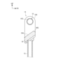
- FIG. 5 is a side cross-sectional view of the left-right center of the handle portion 14.
- the display unit 16 is positioned directly below the center grip portion 15C, and is arranged with the display screen 16A facing rearward and upward.
- Symbol MG in FIG. 5 denotes an inclined surface along the display screen 16A.
- the user holding the handle 15 can easily view the display screen 16A below the handle 15 .
- the display unit 16 is arranged below the handle 15, an empty space can be secured above the handle 15. - ⁇ Therefore, the user holding the handle 15 can easily see the surroundings including the front and left and right, and the user can easily hold the handle 15 . In addition, it becomes easier to avoid a situation in which an infant placed on the housing portion 2 comes into contact with the display unit 16 .
- the display unit 16 is provided within a range that overlaps the enlarged diameter portion 15K in a side view. Therefore, the left and right enlarged diameter portions 15K and the handle 15 can be easily made to function as guard members that guard the left, right, and upper sides of the display unit 16. As shown in FIG. Note that the shape of the enlarged diameter portion 15K and the enlarged diameter portion 15T on the end portion side may be changed within a range in which at least a portion of the diameter of the handle 15 is enlarged in the radial direction, or the left and right grip portions 15L and 15R may be adjusted by the user. and the central gripping portion 15C may be changed within an identifiable range. Furthermore, the shape, size, and position of the display unit 16 may be changed as appropriate.
- the device body 12 has an insertion portion 17 into which the holder body 7A is inserted.
- the insertion portion 17 has a lock pin 17A that functions as a locking portion that locks the inserted holder main body 7A.
- the lock pin 17A moves upward and engages with the holder main body 7A to connect the holder 7 and the device main body 12 together. That is, the insertion portion 17 functions as a connecting portion for connecting with the push cart 1 .
- the lock pin 17A moves up and down integrally with a foot pedal unit 18 which is vertically movably provided on the device main body 12 .
- the foot pedal unit 18 includes a foot portion 18A that is pressed by the user's foot, and when the foot portion 18A is pressed, the locking pin 17A and the holder main body 7A are disengaged.
- the foot pedal unit 18 is configured to be lockable in a downwardly moved state, and in this state the assist device 10 can be removed from the holder 7 .
- left and right auxiliary wheels 19 are provided that come into contact with the road surface when the foot pedal unit 18 is moved downward. It is possible to make it stand on its own.
- the steering wheel axis C1 and the vertical axis C2 orthogonal to the shaft of the drive wheels 11 are offset in the longitudinal direction when viewed from the side of the vehicle body. , can be placed close to the push cart 1.
- the distance between the driving wheel 11 and the auxiliary wheel 19 provided at the position of the handle axis C1 can be increased, so that the stability of the assist device 10 is improved when the assist device 10 is made independent. .
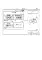
- FIG. 6 is a block diagram showing the electrical configuration of the assist device 10.
- the assist device 10 includes an assist control unit 21 that controls each part of the assist device 10, a drive motor 22 that functions as a drive source for driving the drive wheels 11, and a battery 23 that functions as an energy source for the assist device 10.
- the handle portion 14 includes pressure detection portions 24L and 24R provided on the left and right grip portions 15L and 15R, a pressure detection portion 25 provided on the central grip portion 15C, an operation portion 26 operated by the user, and the assist device 10. and a display unit 16 for displaying the driving state of the.
- the assist control unit 21 includes a CPU and peripheral circuits, and executes a control program stored in the storage unit 27 by the CPU to apply an assist force to the push cart 1 when moving the push cart 1.
- the storage unit 28 stores data such as a speed upper limit value VX and an assist upper limit value PX which are used for control to apply an assist force, which will be described later, and various data used for display.
- the drive motor 22 drives the drive wheels 11 with a driving force corresponding to the assist force under the control of the assist control unit 21. Assisting in this description means assisting the user's force to move the push cart 1 . This assist reduces the user's load. In addition, when the user does not push or pull the cart 1, the drive motor 22 is basically not driven.
- a wheel-in motor is adopted as the drive motor 22 .
- the battery 23 supplies operating power to each part of the assist device 10 .
- a rechargeable battery such as a lithium ion battery is adopted as the battery 23, and the battery 23 is charged by power supply from the outside.
- the pressure detection unit 24L has a sensor that detects an external force (pressure, equivalent to user operation force) acting on the left gripping unit 15L, and has a pressure sensor, for example. Based on the detection result of the pressure detection unit 24L, it specifies whether or not the user is operating the cart 1 in the front-rear direction while gripping the left gripping portion 15L, and the operating force and the operating direction acting on the gripping portion 15L. It is possible.
- the pressure detection unit 24R has a sensor that detects an external force (pressure, equivalent to user operation force) acting on the right grip 15R, and has, for example, a pressure sensor.
- the pressure detection unit 24R Based on the detection result of the pressure detection unit 24R, it specifies whether or not the user is operating the cart 1 in the front-rear direction while gripping the right gripping portion 15R, and the operating force and the operating direction acting on the gripping portion 15R. It is possible.
- the pressure detection unit 24C has a sensor that detects an external force (which can also be referred to as pressure or user operation force) acting on the central grip 15C, and has, for example, a pressure sensor. Based on the detection result of the pressure detection unit 24C, it specifies whether or not the user is operating the cart 1 in the front-rear direction while gripping the central gripping portion 15C, and specifies the operating force and the operating direction acting on the central gripping portion 15C. It is possible. Although it is possible to detect to some extent whether or not the user is gripping the grips 15L, 15R, and 15C only with the pressure sensors, these pressure sensors 24L, 24R and 24C may have other sensors such as capacitive or other touch sensors.
- the touch sensor may be configured to detect whether or not the user is holding each of the holding portions 15L, 15R, and 15C from the image captured by the camera.
- the operation unit 26 has a rotary operator 26A provided on the handle 15.
- the rotary operator 26A is an operator used for switching the operating state of the assist device 10. FIG. The manner in which the rotary operator 26A is operated will be described later.
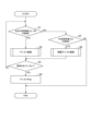
- FIG. 7 is a flow chart showing the basic operation of the assist device 10.
- the assist control section 21 determines whether or not the left and right gripping sections 15L and 15R are gripped based on the detection results of the pressure detecting sections 24L, 24R and 24C (step S1).
- the assist control unit 21 detects an operation force equal to or greater than a predetermined lower limit value in both the gripping units 15L and 15R. It is determined that the gripping portions 15L and 15R are gripped.
- the assist control unit 21 detects touches on both the grips 15L and 15R by the touch sensors, and the left and right grips 15L and 15R are detected by the touch sensors. It is determined that the object is in a gripped state.
- step S1 When the left and right grip portions 15L and 15R are gripped (step S1; YES), that is, when the user is operating with both hands, the assist control portion 21 starts assist control (step S2).
- the assist control unit 21 continues the assist control while the left and right grip portions 15L and 15R are gripped (step S3; YES), and when the left and right grip portions 15L and 15R are not gripped (step S3; NO, stop the assist control (step S4).
- the assist control in step S2 is control to apply an assist force according to the external force (equivalent to the user's operation force) acting on the left and right grips 15L and 15R.
- an average value of the external forces acting on the left and right grips 15L and 15R is detected as the external force, and the assist force is set according to the average value.
- the assist force for example, the drive torque of the drive motor 22 suitable for reducing the user's operation force is set.
- the assisting direction follows the user's operating direction. Therefore, when the user operates the pushcart 1 forward via the grips 15L and 15R, an assist force is applied toward the forward direction. Further, when the user operates the pushcart 1 rearward via the grips 15L and 15R, an assist force is applied to the backward movement side.
- the assist control unit 21 has a function of detecting the running speed via an encoder or the like provided on the drive motor 22 .
- an upper limit value VX of the running speed (hereinafter referred to as speed upper limit value VX) and an upper limit value PX of the assist force (hereinafter referred to as assist upper limit value PX) are set in advance.
- the assist control unit 21 controls the assist force so as not to exceed the speed upper limit value VX and the assist upper limit value PX. That is, the assist control unit 21 controls the assist force and the assist direction according to the combination of the user's operation force, operation direction, and running speed.
- Assist control techniques applied to assisted bicycles and the like can be widely applied to this assist control.
- the drive motor 22 is controlled so that a braking force corresponding to the operation force is applied. You may make it
- the assist control portion 21 determines whether or not the central gripping portion 15C is gripped (step S5).
- the assist control unit 21 detects that the central gripping portion 15C is gripped when an operating force equal to or greater than a predetermined lower limit value is detected in the central gripping portion 15C. determined to be in a state of
- the assist control unit 21 determines that the central gripping portion 15C is gripped when the touch sensor detects the touch of the central gripping portion 15C.
- step S6 When the central gripping portion 15C is gripped (step S5; YES), the assist control portion 21 starts limited assist control (step S6). That is, when it is detected that the left and right grip portions 15L and 15R are not gripped and the center grip portion 15C is gripped, that is, when the user is operating with one hand, the limit assist control is started. be.
- Limited assist control is assist control that is more limited than the assist control in step S2. Specifically, as the limited assist control, a control that provides a lower assist force than the assist control in step S2, and a control that slows down the response speed (corresponding to the rising characteristic of the assist force) to an increase in the external force (user's operation force). , control for lowering the speed upper limit value VX, and control for lowering the assist upper limit value PX.
- the movement of the push cart 1 is greater when the user operates with one hand than when the user operates with both hands. It becomes easier to lower the speed. Further, by performing control with a slow response speed to an increase in external force, it is easier to prevent the push cart 1 from jumping out when the user is operating with one hand than when operating with both hands.
- the assist is weak on the condition that the central grip portion 15C is gripped with one hand. It can be performed.
- step S5 When none of the left and right gripping portions 15L and 15R and the center gripping portion 15C are gripped (step S5; NO), the assist control section 21 performs neither assist control nor limited assist control.
- the above is the basic operation of the assist device 10 .
- FIG. 8 is a diagram showing the rotary operator 26A together with its peripheral configuration.
- the rotary operation element 26A is provided at a position near the left-right center of the right grip portion 15R, and is provided rotatably along the circumferential direction d1 of the handle 15.
- the expanded diameter portion 15K is provided with a state indicator 15P that indicates a plurality of states of the assist device 10. As shown in FIG.
- the status indicator 15P is provided at a position on the steering wheel 15 side that is visible to the user, and includes "OFF” indicating the OFF state of the assist device 10, "P” indicating parking mode, "1” indicating the first assist mode, "2” indicating the second assist mode and “3” indicating the third assist mode are written in the circumferential direction d1 of the steering wheel 15 in this order.
- An indicator 26X that indicates the current state of the assist device 10 is provided on the rotary operator 26A. That is, in FIG. 8, the indicator 26X indicates “2", indicating that the assist device 10 is in the second assist mode.
- the indicator 26X can be changed to a position indicating any one of "P", “1", “2” and "3".
- the assist control unit 21 detects the rotational position of the rotary operator 26A and sets the current state of the assist device 10 according to the rotational position. Therefore, by rotating the rotary operator 26A, the user can easily switch between the parking mode and the first to third assist modes.
- the rotary operator 26A is configured to be movable axially outward d2 of the handle 15 at least when the indicator 26X is at the position indicating "P".
- the user slides the rotary operator 26A axially outward d2 to move the rotary operator 26A to the position where the indicator 26X indicates "1". It is possible to rotate.
- the rotary operator 26A must be slid axially outward d2 to move the rotary operator 26A to the position where the indicator 26X indicates "1” to "3". It is configured so that it cannot be rotated.
- switching between the first to third assist modes can be performed by a single action consisting of a rotating operation of the rotary operator 26A, the switching operation can be performed easily and quickly.
- the above two actions may be performed, or the above one action may be performed.
- a known technique may be applied to the configuration for moving the rotary operator 26A in this way.
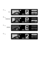
- FIG. 9 is a diagram illustrating a display mode of the display unit 16. As shown in FIG. 9 shows a case where a segment display is adopted as the display unit 16. As shown in FIG. Moreover, FIG. 9 shows a case where the assist device 10 includes a power conversion unit that converts the power of the battery 23, and is capable of AC rated output and USB output using the power conversion unit. Symbol A in FIG. 9 indicates a state in which all segments are displayed, symbol B indicates a display state in parking mode, symbol C indicates an error display state, and symbol D indicates a state in which the second assist mode is displayed. It shows the display state.
- the parking mode is a state in which the drive motor 22 is stopped. If the assist device 10 has an electromagnetic brake, the parking mode is a state in which the electromagnetic brake is activated. In this case, as indicated by symbol B in FIG. 9, "P" indicating the parking mode and the remaining battery level (both 39% in the drawing and a bar display) are displayed. Also, in the parking mode, the battery 23 can be charged, and the AC rated output and USB output functions can be used. Symbol B in FIG. 9 indicates the case where the battery is being charged and the USB output is being used.
- the first to third assist modes are operating states with different assist forces to be applied.
- the speed upper limit value VX differs for each assist mode, and the speed upper limit value VX can be minimized by switching to the first assist mode, and the speed upper limit value VX can be maximized by switching to the third assist mode.
- the speed upper limit value VX can be switched by switching among the first to third assist modes.
- the limit assist control shown in step S6 even in the same assist mode, it is possible to further lower the speed upper limit value VX.
- the response speed (corresponding to the rising characteristic of the assist force) and the assist upper limit value PX may differ between the assist modes.
- the assist mode as indicated by symbol D in FIG. 9, information indicating which of the first to third assist modes is selected ("2" in the figure) and remaining battery power (only bar display). ) and the mileage etc. are displayed.
- the assist control unit 21 detects an error, information indicating that an error has been detected ("E" in the drawing), information indicating the type of error ( "12" in the figure) is displayed. As shown in FIG. 9, on the display unit 16, the information indicating each mode is displayed in a large size at a common position, so that the user can easily grasp the current mode. In addition, since information other than the information indicating each mode and the display of the remaining amount of the battery 23 is changed for each mode, it is possible to display information according to the mode.
- the assist device 10 of the present embodiment detects that the handle 15 having the left and right grip portions 15L and 15R and that the left and right grip portions 15L and 15R are gripped. and an assist control unit 21 that controls the assist force according to the external force acting on the portions 15L and 15R. Further, the handle 15 has a central gripping portion 15C between the left and right gripping portions 15L and 15R, and the assist control portion 21 is configured such that the left and right gripping portions 15L and 15R are not gripped and the central gripping portion 15C is gripped. When it is detected that the grip has been done, the assist force is controlled according to the external force acting on the central grip portion 15C.
- the left and right gripping portions 15L, 15R and the central gripping portion 15C there is an enlarged diameter portion 15K whose diameter is at least partially enlarged. According to this configuration, the user can easily distinguish between the left and right grip portions 15L and 15R and the center grip portion 15C without relying on vision. For example, it is possible to prevent a situation in which the user accidentally grips one of the left and right grip portions 15L and 15R while intending to operate with one hand, and is not assisted.
- the assist control unit 21 detects that the left and right gripping portions 15L and 15R are not gripped and the center gripping portion 15C is gripped, it is determined that the left and right gripping portions 15L and 15R are gripped. is detected, the limit assist force is controlled to be more limited. According to this configuration, when the user operates with one hand, it is possible to provide a weaker assist, so fine control can be performed with only one hand. In this case, the limited assist force is set to a smaller assist force than the assist force when it is detected that the left and right gripping portions 15L and 15R are gripped. It becomes easier to suppress the movement speed of 1. This also allows fine control with just one hand.
- the push cart 1 can be prevented from jumping out. easier to suppress. This also allows fine control with just one hand.
- a display unit 16 functioning as a display section for displaying the drive state of the assist device 10 is provided, and the display unit 16 is positioned below the handle 15 .
- an empty space can be secured above the handle 15 , the user can easily see the surroundings including the front and left and right, and the user can easily grip the handle 15 .
- the handle 15 and the like are less likely to get in the way when moving an infant or an object.
- the end of the handle 15 has an end-side enlarged diameter portion 15T, at least a portion of which is radially enlarged. According to this configuration, the user can easily identify the left and right grip portions 15L and 15R without relying on vision.
- the above-described embodiment shows one aspect of the present invention, and the present invention is not limited to the above-described embodiment.
- the object to be assisted by the assist device 10 is not limited to the push cart 1 shown in FIG. 1 and the like.
- the present invention is applied to the assist device 10 shown in FIG.
- a driving source for generating the assisting force, a driving wheel driven by the assisting force, and a connecting portion for connecting to a predetermined article
- a handle having left and right gripping portions positioned at left and right end portions
- an assist control unit that controls the assist force according to an external force acting on the handle, the handle has a central grip portion between the left and right grip portions, and the assist control unit controls the left and right grips and controlling the assist force according to an external force acting on the central gripping portion when the central gripping portion is detected to be gripped while the central gripping portion is not gripped.
- (Arrangement 2) The assist device according to Arrangement 1, wherein at least a part of the enlarged diameter portion is provided between the left and right gripping portions and the central gripping portion. According to this configuration, the user can easily distinguish between the left and right grips and the central grip without relying on vision.
- (Arrangement 6) The assist device according to any one of Arrangements 1 to 5, further comprising a display section for displaying the driving state of the assist device, wherein the display section is positioned below the handle.
- a display section for displaying the driving state of the assist device, wherein the display section is positioned below the handle.
- an empty space can be secured above the handle, so that the user can easily view the surroundings including the front and left and right, and the user can easily grasp the handle.
- the handle or the like is less likely to get in the way when moving an object or the like.
Landscapes
- Engineering & Computer Science (AREA)
- Chemical & Material Sciences (AREA)
- Combustion & Propulsion (AREA)
- Transportation (AREA)
- Mechanical Engineering (AREA)
- Handcart (AREA)
Abstract
ユーザの利便性を向上すること。 アシスト装置10は、左右の端部側に位置する左右の把持部15L,15Rを有するハンドル15と、左右の把持部15L,15Rが把持されたことを検出している場合、左右の把持部15L,15Rに作用する外力に応じて、アシスト力を制御するアシスト制御部21とを備え、ハンドル15は、左右の把持部15L,15Rの間に中央把持部15Cを有し、アシスト制御部21は、左右の把持部15L,15Rが把持されず、かつ、中央把持部15Cが把持されたことを検出している場合、中央把持部15Cに作用する外力に応じて、アシスト力を制御する。
Description
本発明は、アシスト装置に関する。
所定物品を移動させる際に所定物品に移動のためのアシスト力を付与するアシスト装置が提案されている。特許文献1には、ベッドの一端部に装着される操作機と、ベッドの他端部に装着される走行台車を有し、操作機を両手で操作しないと走行台車を走行させることができないことが記載されている。
従来の構成は、両手操作を条件にアシスト力が付与されるので、アシスト時の安定性向上に有利となる。ところで、この両手操作を条件にアシストする機能に加え、片手がふさがっている場合でもアシストすることができれば、ユーザの利便性がより向上するものと考えられる。
本発明は、上述した事情に鑑みてなされたものであり、ユーザの利便性を向上することを目的とする。
本発明は、上述した事情に鑑みてなされたものであり、ユーザの利便性を向上することを目的とする。
所定物品を移動させる際に前記所定物品に移動のためのアシスト力を付与するアシスト装置において、前記アシスト力を発生する駆動源と、前記アシスト力で駆動される駆動輪と、前記所定物品と連結するための連結部と、左右の端部側に位置する左右の把持部を有するハンドルと、前記左右の把持部が把持されたことを検出している場合、前記左右の把持部に作用する外力に応じて、前記アシスト力を制御するアシスト制御部とを備え、前記ハンドルは、前記左右の把持部の間に中央把持部を有し、前記アシスト制御部は、前記左右の把持部が把持されず、かつ、前記中央把持部が把持されたことを検出している場合、前記中央把持部に作用する外力に応じて、前記アシスト力を制御することを特徴とするアシスト装置。
両手操作を条件にアシストする機能を備えつつ、片手操作することでアシストする機能を備えるので、ユーザの利便性が向上する。
以下、図面を参照して本発明の実施の形態について説明する。
[実施の形態]
図1は、本発明の実施形態に係るアシスト装置を所定物品と共に示す図である。
本実施形態の所定物品は、大型の手押しカート1であり、大型カート、手押し車両、お散歩カー、及び、お散歩カートとも称される。この手押しカート1は、複数の幼児を乗せることができ、例えば、保育士等のユーザが保育施設から公園等の任意の場所へ幼児を移動する際に利用される。
図1は、本発明の実施形態に係るアシスト装置を所定物品と共に示す図である。
本実施形態の所定物品は、大型の手押しカート1であり、大型カート、手押し車両、お散歩カー、及び、お散歩カートとも称される。この手押しカート1は、複数の幼児を乗せることができ、例えば、保育士等のユーザが保育施設から公園等の任意の場所へ幼児を移動する際に利用される。
手押しカート1は、幼児や荷物等を収容する収容部2と、収容部2に設けられた車輪3と、収容部2に設けられた枠状のフレーム4に取り付けられたハンドル5とを有している。車輪3は、転舵不能な左右一対の大型車輪3Aと、大型車輪3Aの周囲に位置する複数のキャスター3Bとを有し、前進、後進、及び左右に旋回可能に構成されている。
手押しカート1のフレーム4には、ホルダー7を介してアシスト装置10が連結される。
ホルダー7は、フレーム4に着脱可能な部材であり、アシスト装置10を利用する場合に、手押しカート1の後部に位置するフレーム4に装着される。
ホルダー7は、手押しカート1に装着された状態で後方に突出するホルダー本体7Aを有し、このホルダー本体7Aにアシスト装置10を着脱自在である。
ホルダー7は、フレーム4に着脱可能な部材であり、アシスト装置10を利用する場合に、手押しカート1の後部に位置するフレーム4に装着される。
ホルダー7は、手押しカート1に装着された状態で後方に突出するホルダー本体7Aを有し、このホルダー本体7Aにアシスト装置10を着脱自在である。
アシスト装置10は、手押しカート1を移動させる際に手押しカート1に移動のためのアシスト力を付与する装置である。つまり、手押しカート1は、アシスト装置10によって移動がアシストされる被移動体と言うこともできる。手押しカート1のハンドル5は、被移動体ハンドルと言うことができ、以下の説明では、「カート側ハンドル5」と表記する。
アシスト装置10は、駆動輪11を有する装置本体12と、装置本体12から上方に延出するハンドル軸13と、ハンドル軸13の上部に取り付けられたハンドル部14とを備えている。
ハンドル部14は、ユーザが操作する操作デバイス、及び、ユーザに情報を出力する出力デバイスとして機能する部分である。ハンドル部14は、左右に延出するハンドル15と、ハンドル15の下方に支持された表示ユニット16と、ユーザが操作する操作部26(図6)とを有している。
ハンドル部14は、ユーザが操作する操作デバイス、及び、ユーザに情報を出力する出力デバイスとして機能する部分である。ハンドル部14は、左右に延出するハンドル15と、ハンドル15の下方に支持された表示ユニット16と、ユーザが操作する操作部26(図6)とを有している。
図2は、アシスト装置10を手押しカート1と共に側方から示す図である。図3は、アシスト装置10を手押しカート1と共に上方から示す図である。
ハンドル軸13は、装置本体12に回動自在に支持され、ハンドル部14と一体に左右に回動する。図2中の符号C1は、ハンドル軸13の中心軸線であり、「ハンドル軸線C1」と適宜に表記する。
ハンドル軸13は、装置本体12の後部から上方に延出し、カート側ハンドル5よりも上方にハンドル15を支持する。ハンドル15は、カート側ハンドル5よりも上方、かつ、収容部2から後方に離れた位置に支持されるので、ハンドル15を回動してもハンドル15がカート側ハンドル5と接触せず、ユーザが容易にハンドル15を左右に操舵可能である。
ハンドル軸13は、装置本体12に回動自在に支持され、ハンドル部14と一体に左右に回動する。図2中の符号C1は、ハンドル軸13の中心軸線であり、「ハンドル軸線C1」と適宜に表記する。
ハンドル軸13は、装置本体12の後部から上方に延出し、カート側ハンドル5よりも上方にハンドル15を支持する。ハンドル15は、カート側ハンドル5よりも上方、かつ、収容部2から後方に離れた位置に支持されるので、ハンドル15を回動してもハンドル15がカート側ハンドル5と接触せず、ユーザが容易にハンドル15を左右に操舵可能である。
表示ユニット16についてもカート側ハンドル5よりも上方、かつ、収容部2から後方に離れた位置に支持される。したがって、ハンドル15を左右に転舵しても表示ユニット16が、手押しカート1に接触することがない。なお、ハンドル15、及び表示ユニット16等の位置は、手押しカート1に接触しない範囲で適宜に変更してもよい。
図4は、ハンドル部14と、装置本体12の内部構造を示す図である。
図4に示すように、ハンドル15は、左右の端部側に位置する左右の把持部15L,15Rと、左右の把持部15L,15Rの間に位置する中央把持部15Cとを有している。左右の把持部15L,15Rは、ユーザが両手で把持するのに好適なハンドル部分である。また、中央把持部15Cは、ユーザが片手で把持することが可能なハンドル部分である。
左右の把持部15L,15Rと中央把持部15Cとの間には、ハンドル15から径方向に拡径する拡径部15Kがそれぞれ設けられている。これら左右の拡径部15Kは、中央把持部15Cの下方に表示ユニット16を支持する支持部としても機能する。これら拡径部15Kによって、左右の把持部15L,15Rと、中央把持部15Cとの境界を、ユーザが視覚だけでなく触感によっても認識し易くなる。
図4に示すように、ハンドル15は、左右の端部側に位置する左右の把持部15L,15Rと、左右の把持部15L,15Rの間に位置する中央把持部15Cとを有している。左右の把持部15L,15Rは、ユーザが両手で把持するのに好適なハンドル部分である。また、中央把持部15Cは、ユーザが片手で把持することが可能なハンドル部分である。
左右の把持部15L,15Rと中央把持部15Cとの間には、ハンドル15から径方向に拡径する拡径部15Kがそれぞれ設けられている。これら左右の拡径部15Kは、中央把持部15Cの下方に表示ユニット16を支持する支持部としても機能する。これら拡径部15Kによって、左右の把持部15L,15Rと、中央把持部15Cとの境界を、ユーザが視覚だけでなく触感によっても認識し易くなる。
ハンドル15の左右の端部(グリップエンドとも称される)には、ハンドル15から径方向に拡径する端部側拡径部15Tがそれぞれ設けられている。左右の端部側拡径部15Tによって、視覚だけでなく触感によってもユーザが左右のグリップエンドを認識できる。
本構成のハンドル15において、左右の拡径部15Kよりも左右外側の領域、かつ、左右の端部側拡径部15Tよりも左右内側の領域が、ユーザが両手で把持する左右の把持部15L,15Rに構成されている。また、ハンドル15において、左右の拡径部15Kの内側の領域が、ユーザが片手で把持する中央把持部15Cに構成されている。
本構成のハンドル15において、左右の拡径部15Kよりも左右外側の領域、かつ、左右の端部側拡径部15Tよりも左右内側の領域が、ユーザが両手で把持する左右の把持部15L,15Rに構成されている。また、ハンドル15において、左右の拡径部15Kの内側の領域が、ユーザが片手で把持する中央把持部15Cに構成されている。
図5は、ハンドル部14の左右中央の側断面を示す図である。
表示ユニット16は、中央把持部15Cの直下に位置し、表示画面16Aを後上方に向けた姿勢で配置される。図5中の符号MGは、表示画面16Aに沿った傾斜面である。これにより、ハンドル15を把持するユーザが、ハンドル15下方の表示画面16Aを容易に視認できる。
表示ユニット16はハンドル15下方に配置されるので、ハンドル15上方に空きスペースを確保できる。したがって、ハンドル15を把持するユーザが、前方及び左右を含む周囲を容易に視認でき、かつ、ユーザがハンドル15を容易に把持し易くなる。また、収容部2に乗せた幼児が表示ユニット16に接触する事態を避け易くなる。
表示ユニット16は、中央把持部15Cの直下に位置し、表示画面16Aを後上方に向けた姿勢で配置される。図5中の符号MGは、表示画面16Aに沿った傾斜面である。これにより、ハンドル15を把持するユーザが、ハンドル15下方の表示画面16Aを容易に視認できる。
表示ユニット16はハンドル15下方に配置されるので、ハンドル15上方に空きスペースを確保できる。したがって、ハンドル15を把持するユーザが、前方及び左右を含む周囲を容易に視認でき、かつ、ユーザがハンドル15を容易に把持し易くなる。また、収容部2に乗せた幼児が表示ユニット16に接触する事態を避け易くなる。
表示ユニット16は、側面視で拡径部15Kと重なる範囲内に設けられる。したがって、左右の拡径部15K、及び、ハンドル15を、表示ユニット16の左右及び上方をガードするガード部材として機能させ易くなる。
なお、拡径部15K、及び端部側拡径部15Tの形状は、ハンドル15から少なくとも一部が径方向に拡径する範囲で変更してもよいし、ユーザが左右の把持部15L,15Rと中央把持部15Cとを識別可能な範囲で変更してもよい。さらに、表示ユニット16の形状やサイズや位置についても適宜に変更してもよい。
なお、拡径部15K、及び端部側拡径部15Tの形状は、ハンドル15から少なくとも一部が径方向に拡径する範囲で変更してもよいし、ユーザが左右の把持部15L,15Rと中央把持部15Cとを識別可能な範囲で変更してもよい。さらに、表示ユニット16の形状やサイズや位置についても適宜に変更してもよい。
図4に示すように、装置本体12は、ホルダー本体7Aが挿入される挿入部17を有している。挿入部17は、挿入されたホルダー本体7Aに係止する係止部として機能するロックピン17Aを有する。ロックピン17Aは、挿入部17にホルダー本体7Aが挿入されると、上方に移動してホルダー本体7Aに係合し、ホルダー7と装置本体12とを連結する。つまり、挿入部17は、手押しカート1と連結するための連結部として機能する。
ロックピン17Aは、装置本体12に上下に移動自在に設けられたフットペダルユニット18と一体に上下する。フットペダルユニット18は、ユーザの足で押下されるフット部18Aを備え、フット部18Aが押下されると、ロックピン17Aとホルダー本体7Aとの係合を解除する。
フットペダルユニット18は、下方に移動した状態にロック可能に構成され、この状態にすることでアシスト装置10をホルダー7から取り外すことができる。フットペダルユニット18の下部には、フットペダルユニット18を下方に移動させたときに路面に接する左右の補助輪19が設けられ、これら補助輪19と駆動輪11とによって、アシスト装置10を単独で自立させることが可能である。
フットペダルユニット18は、下方に移動した状態にロック可能に構成され、この状態にすることでアシスト装置10をホルダー7から取り外すことができる。フットペダルユニット18の下部には、フットペダルユニット18を下方に移動させたときに路面に接する左右の補助輪19が設けられ、これら補助輪19と駆動輪11とによって、アシスト装置10を単独で自立させることが可能である。
本構成では、図4に示すように、車体側面視で、ハンドル軸線C1と、駆動輪11の軸に直交する鉛直軸線C2とを前後方向にオフセットしているので、駆動輪11を含む部分を、手押しカート1に寄せて配置できる。また、車体側面視で、駆動輪11と、ハンドル軸線C1の位置に設けた補助輪19との前後の離間距離を稼ぐことができるので、アシスト装置10を自立させたときの安定性が向上する。
図6は、アシスト装置10の電気的構成を示すブロック図である。
アシスト装置10は、アシスト装置10の各部を制御するアシスト制御部21と、駆動輪11を駆動する駆動源として機能する駆動モータ22と、アシスト装置10のエネルギー源として機能するバッテリー23とを備えている。
ハンドル部14は、左右の把持部15L,15Rに設けられた圧力検出部24L,24Rと、中央把持部15Cに設けられた圧力検出部25と、ユーザが操作する操作部26と、アシスト装置10の駆動状態等を表示する表示ユニット16とを備えている。
アシスト装置10は、アシスト装置10の各部を制御するアシスト制御部21と、駆動輪11を駆動する駆動源として機能する駆動モータ22と、アシスト装置10のエネルギー源として機能するバッテリー23とを備えている。
ハンドル部14は、左右の把持部15L,15Rに設けられた圧力検出部24L,24Rと、中央把持部15Cに設けられた圧力検出部25と、ユーザが操作する操作部26と、アシスト装置10の駆動状態等を表示する表示ユニット16とを備えている。
アシスト制御部21は、CPU及び周辺回路を備え、CPUによって記憶部27に記憶された制御プログラムを実行することによって、手押しカート1を移動させる際に、手押しカート1に移動のためのアシスト力を付与する制御を行う。
記憶部28には、制御プログラムに加えて、アシスト力を付与する後述する制御に使用する速度上限値VX及びアシスト上限値PX等のデータ、及び表示に使用する各種のデータ等が記憶される。
記憶部28には、制御プログラムに加えて、アシスト力を付与する後述する制御に使用する速度上限値VX及びアシスト上限値PX等のデータ、及び表示に使用する各種のデータ等が記憶される。
駆動モータ22は、アシスト制御部21の制御の下、アシスト力に応じた駆動力で駆動輪11を駆動する。本説明中のアシストとは、ユーザが手押しカート1を移動する力を補助することである。このアシストによってユーザの負荷が軽減される。なお、ユーザが手押しカート1を押し引きしていない場合、駆動モータ22は基本的に駆動されない。
駆動モータ22には、ホイールインモータが採用される。バッテリー23は、アシスト装置10の各部に動作電力を供給する。このバッテリー23には、リチウムイオンバッテリー等の充電可能なバッテリーが採用され、外部からの給電によってバッテリー23が充電される。
圧力検出部24Lは、左の把持部15Lに作用する外力(圧力、ユーザ操作力に相当)を検出するセンサーを有し、例えば、圧力センサーを有する。圧力検出部24Lの検出結果に基づいて、ユーザが左の把持部15Lを把持した状態で前後方向に手押しカート1を操作しているか否か、把持部15Lに作用する操作力及び操作方向を特定可能である。
圧力検出部24Rは、右の把持部15Rに作用する外力(圧力、ユーザ操作力に相当)を検出するセンサーを有し、例えば、圧力センサーを有する。圧力検出部24Rの検出結果に基づいて、ユーザが右の把持部15Rを把持した状態で前後方向に手押しカート1を操作しているか否か、把持部15Rに作用する操作力及び操作方向を特定可能である。
圧力検出部24Rは、右の把持部15Rに作用する外力(圧力、ユーザ操作力に相当)を検出するセンサーを有し、例えば、圧力センサーを有する。圧力検出部24Rの検出結果に基づいて、ユーザが右の把持部15Rを把持した状態で前後方向に手押しカート1を操作しているか否か、把持部15Rに作用する操作力及び操作方向を特定可能である。
圧力検出部24Cは、中央把持部15Cに作用する外力(圧力、ユーザ操作力ということもできる)を検出するセンサーを有し、例えば、圧力センサーを有する。圧力検出部24Cの検出結果に基づいて、ユーザが中央把持部15Cを把持した状態で前後方向に手押しカート1を操作しているか否か、中央把持部15Cに作用する操作力及び操作方向を特定可能である。
なお、圧力センサーだけでも、各把持部15L,15R及び15Cをユーザが把持しているか否かをある程度検出することは可能であるが、より高精度に検出することを目的として、これら圧力検出部24L,24R及び24Cが、静電容量式等のタッチセンサー等の他のセンサーを有するようにしてもよい。タッチセンサーは、カメラの撮影画像から、各把持部15L,15R及び15Cをユーザが把持しているか否かを検出する構成でもよい。
なお、圧力センサーだけでも、各把持部15L,15R及び15Cをユーザが把持しているか否かをある程度検出することは可能であるが、より高精度に検出することを目的として、これら圧力検出部24L,24R及び24Cが、静電容量式等のタッチセンサー等の他のセンサーを有するようにしてもよい。タッチセンサーは、カメラの撮影画像から、各把持部15L,15R及び15Cをユーザが把持しているか否かを検出する構成でもよい。
操作部26は、ハンドル15に設けられた回転操作子26Aを有している。回転操作子26Aは、アシスト装置10の動作状態の切り換えに使用される操作子である。この回転操作子26Aの操作態様については後述する。
図7は、アシスト装置10の基本動作を示すフローチャートである。
アシスト制御部21は、圧力検出部24L,24R及び24Cの検出結果に基づいて、左右の把持部15L,15Rが把持された状態か否かを判定する(ステップS1)。
ここで、圧力検出部24L,24Rが圧力しか検出できない構成の場合、アシスト制御部21は、把持部15L,15Rの両方に予め定めた下限値以上の操作力が検出されていれば、左右の把持部15L,15Rが把持された状態と判定する。一方、圧力検出部24L,24Rがタッチセンサーを有する場合、アシスト制御部21は、タッチセンサーによって把持部15L,15Rの両方へのタッチを検出している場合に、左右の把持部15L,15Rが把持された状態と判定する。
アシスト制御部21は、圧力検出部24L,24R及び24Cの検出結果に基づいて、左右の把持部15L,15Rが把持された状態か否かを判定する(ステップS1)。
ここで、圧力検出部24L,24Rが圧力しか検出できない構成の場合、アシスト制御部21は、把持部15L,15Rの両方に予め定めた下限値以上の操作力が検出されていれば、左右の把持部15L,15Rが把持された状態と判定する。一方、圧力検出部24L,24Rがタッチセンサーを有する場合、アシスト制御部21は、タッチセンサーによって把持部15L,15Rの両方へのタッチを検出している場合に、左右の把持部15L,15Rが把持された状態と判定する。
左右の把持部15L,15Rが把持された状態の場合(ステップS1;YES)、つまり、ユーザが両手操作している場合、アシスト制御部21は、アシスト制御を開始する(ステップS2)。
アシスト制御部21は、左右の把持部15L,15Rが把持される間(ステップS3;YES)、アシスト制御を継続し、左右の把持部15L,15Rが把持されていない状態になると(ステップS3;NO、アシスト制御を中止する(ステップS4)。
アシスト制御部21は、左右の把持部15L,15Rが把持される間(ステップS3;YES)、アシスト制御を継続し、左右の把持部15L,15Rが把持されていない状態になると(ステップS3;NO、アシスト制御を中止する(ステップS4)。
ステップS2のアシスト制御(通常アシスト制御と言うこともできる)について説明する。
ステップS2のアシスト制御は、左右の把持部15L,15Rに作用する外力(ユーザの操作力に相当)に応じたアシスト力を付与する制御である。例えば、外力として、左右の把持部15L,15Rに作用する外力の平均値を検出し、平均値に応じてアシスト力を設定する。ユーザの左右平均の操作力に合わせてアシスト力を設定することで、ユーザに適切なアシスト力を付与し易くなる。アシスト力としては、例えば、ユーザの操作力の軽減に適した駆動モータ22の駆動トルクが設定される。
ステップS2のアシスト制御は、左右の把持部15L,15Rに作用する外力(ユーザの操作力に相当)に応じたアシスト力を付与する制御である。例えば、外力として、左右の把持部15L,15Rに作用する外力の平均値を検出し、平均値に応じてアシスト力を設定する。ユーザの左右平均の操作力に合わせてアシスト力を設定することで、ユーザに適切なアシスト力を付与し易くなる。アシスト力としては、例えば、ユーザの操作力の軽減に適した駆動モータ22の駆動トルクが設定される。
なお、アシストする方向は、ユーザの操作方向に従う。したがって、ユーザが把持部15L,15Rを介して手押しカート1を前方に操作すれば、前進側へのアシスト力が付与される。また、ユーザが把持部15L,15Rを介して手押しカート1を後方に操作すれば、後進側へのアシスト力が付与される。
アシスト制御部21は、駆動モータ22に設けられたエンコーダ等を介して走行速度を検出する機能を備えている。本構成では、走行速度の上限値VX(以下、速度上限値VX)、及びアシスト力の上限値PX(以下、アシスト上限値PX)が予め設定されている。
アシスト制御部21は、速度上限値VX、及び、アシスト上限値PXを超えないように、アシスト力を制御する。つまり、アシスト制御部21は、ユーザの操作力、操作方向、及び走行速度の組み合わせに応じて、アシスト力、及びアシストの方向を制御する。このアシスト制御には、アシスト自転車等に適用されるアシスト制御の技術を広く適用可能である。また、手押しカート1の走行中に、ユーザが把持部15L,15Rを介して走行方向と反対に操作力を加えた場合、その操作力に応じたブレーキ力が作動するように駆動モータ22を制御するようにしてもよい。
アシスト制御部21は、速度上限値VX、及び、アシスト上限値PXを超えないように、アシスト力を制御する。つまり、アシスト制御部21は、ユーザの操作力、操作方向、及び走行速度の組み合わせに応じて、アシスト力、及びアシストの方向を制御する。このアシスト制御には、アシスト自転車等に適用されるアシスト制御の技術を広く適用可能である。また、手押しカート1の走行中に、ユーザが把持部15L,15Rを介して走行方向と反対に操作力を加えた場合、その操作力に応じたブレーキ力が作動するように駆動モータ22を制御するようにしてもよい。
左右の把持部15L,15Rが把持されていない状態の場合(ステップS1;NO)、アシスト制御部21は、中央把持部15Cが把持された状態か否かを判定する(ステップS5)。
ここで、圧力検出部25が圧力しか検出できない構成の場合、アシスト制御部21は、中央把持部15Cに予め定めた下限値以上の操作力が検出されていれば、中央把持部15Cが把持された状態と判定する。一方、圧力検出部25がタッチセンサーを有する場合、アシスト制御部21は、タッチセンサーにより中央把持部15Cのタッチを検出している場合に、中央把持部15Cが把持された状態と判定する。
ここで、圧力検出部25が圧力しか検出できない構成の場合、アシスト制御部21は、中央把持部15Cに予め定めた下限値以上の操作力が検出されていれば、中央把持部15Cが把持された状態と判定する。一方、圧力検出部25がタッチセンサーを有する場合、アシスト制御部21は、タッチセンサーにより中央把持部15Cのタッチを検出している場合に、中央把持部15Cが把持された状態と判定する。
中央把持部15Cが把持された状態の場合(ステップS5;YES)、アシスト制御部21は、制限アシスト制御を開始する(ステップS6)。つまり、左右の把持部15L,15Rが把持されず、かつ、中央把持部15Cが把持されたことを検出している場合、つまり、ユーザが片手操作している場合に、制限アシスト制御が開始される。
制限アシスト制御は、ステップS2のアシスト制御よりも制限したアシスト制御である。具体的には、制限アシスト制御として、ステップS2のアシスト制御と比べ、低いアシスト力を付与する制御、外力(ユーザの操作力)の増大に対する応答速度(アシスト力の立ち上がり特性に相当)が遅い制御、速度上限値VXを下げた制御、及び、アシスト上限値PXを下げた制御の少なくともいずれかを行う。
小さいアシスト力を付与したり、速度上限値VXを下げたり、アシスト上限値PXを下げたりすることで、ユーザが片手操作している場合、両手操作している場合よりも、手押しカート1の移動速度を低速度化し易くなる。また、外力の増大に対する応答速度が遅い制御を行うことで、ユーザが片手操作している場合、両手操作している場合よりも、手押しカート1の飛び出しを抑え易くなる。
このように、本実施形態では、ユーザの両手操作を条件にアシストする機能を備えつつ、ユーザの片手がふさがっているときは、中央把持部15Cを片手で把持することを条件にして弱めのアシストを行うことができる。
このように、本実施形態では、ユーザの両手操作を条件にアシストする機能を備えつつ、ユーザの片手がふさがっているときは、中央把持部15Cを片手で把持することを条件にして弱めのアシストを行うことができる。
左右の把持部15L,15R、及び中央把持部15Cのいずれも把持されていない場合(ステップS5;NO)、アシスト制御部21は、アシスト制御、及び制限アシスト制御のいずれも行わない。以上がアシスト装置10の基本動作である。
次に、回転操作子26A、及び表示ユニット16の表示態様を説明する。
図8は、回転操作子26Aを周辺構成と共に示す図である。
回転操作子26Aは、右側の把持部15Rにおける左右中央寄りの位置に設けられ、ハンドル15の周方向d1に沿って回動自在に設けられている。
拡径部15Kには、アシスト装置10が備える複数の状態を示す状態表示体15Pが設けられている。状態表示体15Pは、ハンドル15側のユーザが視認可能な位置に設けられ、アシスト装置10のオフ状態を示す「OFF」、パーキングモードを示す「P」、第1アシストモードを示す「1」、第2アシストモードを示す「2」、及び第3アシストモードを示す「3」が、ハンドル15の周方向d1に順に表記されている。
図8は、回転操作子26Aを周辺構成と共に示す図である。
回転操作子26Aは、右側の把持部15Rにおける左右中央寄りの位置に設けられ、ハンドル15の周方向d1に沿って回動自在に設けられている。
拡径部15Kには、アシスト装置10が備える複数の状態を示す状態表示体15Pが設けられている。状態表示体15Pは、ハンドル15側のユーザが視認可能な位置に設けられ、アシスト装置10のオフ状態を示す「OFF」、パーキングモードを示す「P」、第1アシストモードを示す「1」、第2アシストモードを示す「2」、及び第3アシストモードを示す「3」が、ハンドル15の周方向d1に順に表記されている。
回転操作子26Aには、アシスト装置10の現在の状態を示すインジケータ26Xが設けられている。
つまり、図8では、インジケータ26Xが「2」を指し示しており、アシスト装置10が第2アシストモードであることを示している。回転操作子26Aをハンドル15の周方向d1に回転することによって、インジケータ26Xを、「P」、「1」、「2」及び「3」のいずれかを指し示す位置に変更できる。
アシスト制御部21は、回転操作子26Aの回転位置を検出し、回転位置に応じてアシスト装置10の現在の状態を設定する。したがって、回転操作子26Aを回転操作することによって、ユーザは、パーキングモード、第1~第3アシストモードに容易に切り換えることができる。
つまり、図8では、インジケータ26Xが「2」を指し示しており、アシスト装置10が第2アシストモードであることを示している。回転操作子26Aをハンドル15の周方向d1に回転することによって、インジケータ26Xを、「P」、「1」、「2」及び「3」のいずれかを指し示す位置に変更できる。
アシスト制御部21は、回転操作子26Aの回転位置を検出し、回転位置に応じてアシスト装置10の現在の状態を設定する。したがって、回転操作子26Aを回転操作することによって、ユーザは、パーキングモード、第1~第3アシストモードに容易に切り換えることができる。
回転操作子26Aは、少なくともインジケータ26Xが「P」を示す位置の場合、ハンドル15の軸方向外側d2に移動可能に構成されている。インジケータ26Xが「P」を示す位置の場合、ユーザが、回転操作子26Aを軸方向外側d2にスライドさせた状態にすることで、インジケータ26Xが「1」を示す位置まで、回転操作子26Aを回転させることが可能になる。
換言すると、インジケータ26Xが「P」を示す位置の場合、回転操作子26Aを軸方向外側d2にスライドさせなければ、インジケータ26Xが「1」~「3」を示す位置へ、回転操作子26Aを回転させることはできないように構成されている。
換言すると、インジケータ26Xが「P」を示す位置の場合、回転操作子26Aを軸方向外側d2にスライドさせなければ、インジケータ26Xが「1」~「3」を示す位置へ、回転操作子26Aを回転させることはできないように構成されている。
したがって、アシスト装置10を、パーキングモードからアシストモードへ切り換える場合に、ハンドル15の軸方向外側d2の操作と、ハンドル15の周方向d1回転操作とからなる2アクションの操作が必要となる。これにより、回転操作子26Aの回転操作からなるワンアクションで、アシスト装置10がパーキングモードからアシストモードに切り替わってしまう事態を回避できる。
また、第1~第3アシストモード間の切り換えについては、回転操作子26Aの回転操作からなるワンアクションで可能であるので、容易かつ迅速に切り換え操作できる。
なお、パーキングモードからオフ状態への切り換えを行う際は、上記2アクションで行うようにしてもよいし、上記1アクションで行うようにしてもよい。このように回転操作子26Aを移動させる構成については、公知の技術を適用すればよい。
なお、パーキングモードからオフ状態への切り換えを行う際は、上記2アクションで行うようにしてもよいし、上記1アクションで行うようにしてもよい。このように回転操作子26Aを移動させる構成については、公知の技術を適用すればよい。
図9は、表示ユニット16の表示態様を例示する図である。なお、図9は、表示ユニット16にセグメント表示器を採用した場合を示している。また、図9は、アシスト装置10が、バッテリー23の電力を変換する電力変換部を備え、電力変換部を利用してAC定格出力、及びUSB出力が可能な場合を示している。
図9中の符号Aは、全てのセグメントを表示した状態を示し、符号Bは、パーキングモードの表示状態を示し、符号Cは、エラーの表示状態を示し、符号Dは、第2アシストモードの表示状態を示している。
図9中の符号Aは、全てのセグメントを表示した状態を示し、符号Bは、パーキングモードの表示状態を示し、符号Cは、エラーの表示状態を示し、符号Dは、第2アシストモードの表示状態を示している。
パーキングモードは、駆動モータ22を停止させた状態である。このアシスト装置10が電磁ブレーキを有する場合、パーキングモードは、電磁ブレーキを作動させた状態である。この場合、図9の符号Bに示すように、パーキングモードを示す「P」、及び、バッテリー残量(図中の39%と、バー表示の両方で示す)が表示される。また、パーキングモードでは、バッテリー23を充電したり、AC定格出力、及びUSB出力の機能を利用したりすることができる。図9の符号Bには、充電中であり、かつ、USB出力を利用している場合を示している。
第1~第3アシストモードは、付与するアシスト力が異なる動作状態である。例えば、アシストモード毎に速度上限値VXが異なり、第1アシストモードにすることで速度上限値VXを最も低くでき、第3アシストモードにすることで速度上限値VXを最も高くすることができる。図7のステップS2に示すアシスト制御では、第1~第3アシストモードの中で切り換えることによって速度上限値VXを切り換えることができる。また、ステップS6に示す制限アシスト制御の場合、同じアシストモードでも、速度上限値VXをより下げることが可能になる。
なお、アシストモード間で、応答速度(アシスト力の立ち上がり特性に相当)、及び、アシスト上限値PXを異ならせてもよい。
アシストモードの場合、図9の符号Dに示すように、第1~第3アシストモードのうちのどのモードであるかを示す情報(図中の「2」)と、バッテリー残量(バー表示のみ)と、走行距離等が表示される。
なお、アシストモード間で、応答速度(アシスト力の立ち上がり特性に相当)、及び、アシスト上限値PXを異ならせてもよい。
アシストモードの場合、図9の符号Dに示すように、第1~第3アシストモードのうちのどのモードであるかを示す情報(図中の「2」)と、バッテリー残量(バー表示のみ)と、走行距離等が表示される。
また、アシスト制御部21がエラーを検出した場合、図9の符号Cに示すように、エラーを検出した状態であることを示す情報(図中の「E」)、エラーの種別を示す情報(図中の「12」)が表示される。
図9に示すように、表示ユニット16には、各モードを示す情報が共通の位置に大きく表示されるので、ユーザが現在のモードを容易に把握できる。また、各モードを示す情報やバッテリー23の残量表示以外は、モード毎に変更するので、モードに合わせた情報表示が可能になる。
図9に示すように、表示ユニット16には、各モードを示す情報が共通の位置に大きく表示されるので、ユーザが現在のモードを容易に把握できる。また、各モードを示す情報やバッテリー23の残量表示以外は、モード毎に変更するので、モードに合わせた情報表示が可能になる。
以上説明したように、本実施形態のアシスト装置10は、左右の把持部15L,15Rを有するハンドル15と、左右の把持部15L,15Rが把持されたことを検出している場合、左右の把持部15L,15Rに作用する外力に応じて、アシスト力を制御するアシスト制御部21とを備えている。また、ハンドル15は、左右の把持部15L,15Rの間に中央把持部15Cを有し、アシスト制御部21は、左右の把持部15L,15Rが把持されず、かつ、中央把持部15Cが把持されたことを検出している場合、中央把持部15Cに作用する外力に応じてアシスト力を制御する。
この構成によれば、両手操作を条件にアシストする機能を備えつつ、中央把持部15Cを操作することを条件にアシストすることができる。したがって、ユーザの片手がふさがっていても、中央把持部15Cを片手操作することでアシストする機能が働き、ユーザの利便性が向上する。また、片手で操作する場合は、ハンドル15の中央部分を把持するので、ハンドル15の端部を把持する場合よりも操作し易く、操作安全性も比較的高い状態でアシストすることができる。特にハンドル15を転舵しないときに片手で操作することが有効である。
また、左右の把持部15L,15Rと中央把持部15Cとの間に、少なくとも一部が拡径する拡径部15Kを有している。この構成によれば、ユーザが視覚に頼らずに、左右の把持部15L,15Rと中央把持部15Cとを識別し易くなる。例えば、ユーザが片手で操作するつもりが、誤って左右の把持部15L,15Rのいずれかを把持し、アシストされない事態を防止できる。
また、アシスト制御部21は、左右の把持部15L,15Rが把持されず、かつ、中央把持部15Cが把持されたことを検出している場合、左右の把持部15L,15Rが把持されたことを検出している場合よりも制限した制限アシスト力に制御する。この構成によれば、ユーザが片手操作するときは弱めにアシストすることができるため、片手だけでも細やかなコントロールが可能になる。
この場合、制限アシスト力を、左右の把持部15L,15Rが把持されたことを検出している場合のアシスト力よりも出力を制限したアシスト力にすることで、小さいアシスト力とされ、手押しカート1の移動速度を抑え易くなる。これによっても、片手だけでも細やかなコントロールが可能になる。
また、制限アシスト力を、左右の把持部15L,15Rが把持されたことを検出している場合のアシスト力よりも外力の増大に対する応答速度が遅いものとすることで、手押しカート1の飛び出しを抑え易くなる。これによっても、片手だけでも細やかなコントロールが可能になる。
この場合、制限アシスト力を、左右の把持部15L,15Rが把持されたことを検出している場合のアシスト力よりも出力を制限したアシスト力にすることで、小さいアシスト力とされ、手押しカート1の移動速度を抑え易くなる。これによっても、片手だけでも細やかなコントロールが可能になる。
また、制限アシスト力を、左右の把持部15L,15Rが把持されたことを検出している場合のアシスト力よりも外力の増大に対する応答速度が遅いものとすることで、手押しカート1の飛び出しを抑え易くなる。これによっても、片手だけでも細やかなコントロールが可能になる。
また、アシスト装置10の駆動状態を表示する表示部として機能する表示ユニット16を備え、表示ユニット16は、ハンドル15の下方に位置する。この構成によれば、ハンドル15の上方に空きスペースを確保でき、ユーザが、前方及び左右を含む周囲を容易に視認でき、かつ、ユーザがハンドル15を容易に把持し易くなる。また、幼児や物を移動する際にハンドル15等が邪魔になり難い。
また、ハンドル15の端部に、少なくとも一部が径方向に拡径する端部側拡径部15Tを有している。この構成によれば、ユーザが視覚に頼らずに、左右の把持部15L,15Rを識別し易くなる。
なお、上述の実施形態は本発明の一態様を示すものであり、本発明は上述の実施形態に限定されるものではない。例えば、アシスト装置10のアシスト対象は、図1等に示す手押しカート1に限定されない。また、本発明を、図1等に示すアシスト装置10に適用する場合を説明したが、これに限定されず、アシスト装置10の構造及び形状は適宜に変更してもよい。
[上記実施の形態によりサポートされる構成]
上記実施の形態は、以下の構成をサポートする。
上記実施の形態は、以下の構成をサポートする。
(構成1)所定物品を移動させる際に前記所定物品に移動のためのアシスト力を付与するアシスト装置において、前記アシスト力を発生する駆動源と、前記アシスト力で駆動される駆動輪と、前記所定物品と連結するための連結部と、左右の端部側に位置する左右の把持部を有するハンドルと、前記左右の把持部が把持されたことを検出している場合、前記左右の把持部に作用する外力に応じて、前記アシスト力を制御するアシスト制御部とを備え、前記ハンドルは、前記左右の把持部の間に中央把持部を有し、前記アシスト制御部は、前記左右の把持部が把持されず、かつ、前記中央把持部が把持されたことを検出している場合、前記中央把持部に作用する外力に応じて、前記アシスト力を制御することを特徴とするアシスト装置。
この構成によれば、両手操作を条件にアシストする機能を備えつつ、中央把持部を片手操作することでアシストする機能が働き、ユーザの利便性が向上する。
この構成によれば、両手操作を条件にアシストする機能を備えつつ、中央把持部を片手操作することでアシストする機能が働き、ユーザの利便性が向上する。
(構成2)左右の把持部と前記中央把持部との間に、少なくとも一部が拡径する拡径部を有していることを特徴とする構成1に記載のアシスト装置。
この構成によれば、ユーザが視覚に頼らずに、左右の把持部と中央把持部とを識別し易くなる。
この構成によれば、ユーザが視覚に頼らずに、左右の把持部と中央把持部とを識別し易くなる。
(構成3)前記アシスト制御部は、前記左右の把持部が把持されず、かつ、前記中央把持部が把持されたことを検出している場合、前記左右の把持部が把持されたことを検出している場合よりも制限した制限アシスト力に制御することを特徴とする構成1又は2に記載のアシスト装置。
この構成によれば、ユーザが片手操作するときは弱めにアシストすることができるため、片手だけでも細やかなコントロールが可能になる。
この構成によれば、ユーザが片手操作するときは弱めにアシストすることができるため、片手だけでも細やかなコントロールが可能になる。
(構成4)前記制限アシスト力は、前記左右の把持部が把持されたことを検出している場合のアシスト力よりも出力を制限したアシスト力であることを特徴とする構成3に記載のアシスト装置。
この構成によれば、所定物品の移動速度を抑え易くなるため、片手だけでも細やかなコントロールが可能になる。
この構成によれば、所定物品の移動速度を抑え易くなるため、片手だけでも細やかなコントロールが可能になる。
(構成5)前記制限アシスト力は、前記左右の把持部が把持されたことを検出している場合のアシスト力よりも、外力の増大に対する応答速度が遅いことを特徴とする請求項3に記載のアシスト装置。
この構成によれば、所定物品の飛び出しを抑え易くなるため、片手だけでも細やかなコントロールが可能になる。
この構成によれば、所定物品の飛び出しを抑え易くなるため、片手だけでも細やかなコントロールが可能になる。
(構成6)前記アシスト装置の駆動状態を表示する表示部を備え、前記表示部は、前記ハンドルの下方に位置することを特徴とする構成1から5のいずれか一項に記載のアシスト装置。
この構成によれば、ハンドル上方に空きスペースを確保でき、ユーザが、前方及び左右を含む周囲を容易に視認でき、かつ、ユーザがハンドルを容易に把持し易くなる。また、物等を移動する際に、ハンドル等が邪魔になり難い。
この構成によれば、ハンドル上方に空きスペースを確保でき、ユーザが、前方及び左右を含む周囲を容易に視認でき、かつ、ユーザがハンドルを容易に把持し易くなる。また、物等を移動する際に、ハンドル等が邪魔になり難い。
(構成7)前記ハンドルの端部に、少なくとも一部が径方向に拡径する端部側拡径部を有していることを特徴とする構成1から6のいずれか一項に記載のアシスト装置。
この構成によれば、ユーザが視覚に頼らずに、左右の把持部を識別し易くなる。
この構成によれば、ユーザが視覚に頼らずに、左右の把持部を識別し易くなる。
1 手押しカート(所定物品)
5 カート側ハンドル
11 駆動輪
14 ハンドル部
15 ハンドル
15L,15R 左右の把持部
15C 中央把持部
15K 拡径部
16 表示ユニット
17 挿入部(連結部)
21 アシスト制御部
22 駆動モータ(駆動源)
23 バッテリー
24L,24R,24C 圧力検出部
26 操作部
26A 回転操作部
5 カート側ハンドル
11 駆動輪
14 ハンドル部
15 ハンドル
15L,15R 左右の把持部
15C 中央把持部
15K 拡径部
16 表示ユニット
17 挿入部(連結部)
21 アシスト制御部
22 駆動モータ(駆動源)
23 バッテリー
24L,24R,24C 圧力検出部
26 操作部
26A 回転操作部
Claims (7)
- 所定物品(1)を移動させる際に前記所定物品(1)に移動のためのアシスト力を付与するアシスト装置において、
前記アシスト力を発生する駆動源(22)と、
前記アシスト力で駆動される駆動輪(11)と、
前記所定物品と連結するための連結部(17)と、
左右の端部側に位置する左右の把持部(15L,15R)を有するハンドル(15)と、
前記左右の把持部(15L,15R)が把持されたことを検出している場合、前記左右の把持部(15L,15R)に作用する外力に応じて、前記アシスト力を制御するアシスト制御部(21)とを備え、
前記ハンドル(15)は、前記左右の把持部(15L,15R)の間に中央把持部(15C)を有し、
前記アシスト制御部(21)は、前記左右の把持部(15L,15R)が把持されず、かつ、前記中央把持部(15C)が把持されたことを検出している場合、前記中央把持部(15C)に作用する外力に応じて、前記アシスト力を制御することを特徴とするアシスト装置。 - 前記左右の把持部(15L,15R)と前記中央把持部(15C)との間に、少なくとも一部が拡径する拡径部(15K)を有していることを特徴とする請求項1に記載のアシスト装置。
- 前記アシスト制御部(21)は、前記左右の把持部(15L,15R)が把持されず、かつ、前記中央把持部(15C)が把持されたことを検出している場合、前記左右の把持部(15L,15R)が把持されたことを検出している場合よりも制限した制限アシスト力に制御することを特徴とする請求項1又は2に記載のアシスト装置。
- 前記制限アシスト力は、前記左右の把持部(15L,15R)が把持されたことを検出している場合のアシスト力よりも出力を制限したアシスト力であることを特徴とする請求項3に記載のアシスト装置。
- 前記制限アシスト力は、前記左右の把持部(15L,15R)が把持されたことを検出している場合のアシスト力よりも、外力の増大に対する応答速度が遅いことを特徴とする請求項3に記載のアシスト装置。
- 前記アシスト装置の駆動状態を表示する表示部(16)を備え、
前記表示部(16)は、前記ハンドル(15)の下方に位置することを特徴とする請求項1から5のいずれか一項に記載のアシスト装置。 - 前記ハンドル(15)の端部に、少なくとも一部が径方向に拡径する端部側拡径部(15T)を有していることを特徴とする請求項1から6のいずれか一項に記載のアシスト装置。
Priority Applications (1)
| Application Number | Priority Date | Filing Date | Title |
|---|---|---|---|
| PCT/JP2021/047385 WO2023119435A1 (ja) | 2021-12-21 | 2021-12-21 | アシスト装置 |
Applications Claiming Priority (1)
| Application Number | Priority Date | Filing Date | Title |
|---|---|---|---|
| PCT/JP2021/047385 WO2023119435A1 (ja) | 2021-12-21 | 2021-12-21 | アシスト装置 |
Publications (1)
| Publication Number | Publication Date |
|---|---|
| WO2023119435A1 true WO2023119435A1 (ja) | 2023-06-29 |
Family
ID=86901661
Family Applications (1)
| Application Number | Title | Priority Date | Filing Date |
|---|---|---|---|
| PCT/JP2021/047385 Ceased WO2023119435A1 (ja) | 2021-12-21 | 2021-12-21 | アシスト装置 |
Country Status (1)
| Country | Link |
|---|---|
| WO (1) | WO2023119435A1 (ja) |
Citations (5)
| Publication number | Priority date | Publication date | Assignee | Title |
|---|---|---|---|---|
| US4444284A (en) * | 1979-05-18 | 1984-04-24 | Big Joe Manufacturing Company | Control system |
| JPH10109647A (ja) * | 1996-10-08 | 1998-04-28 | Suzuki Motor Corp | 電動アシスト台車 |
| JP2013086547A (ja) * | 2011-10-13 | 2013-05-13 | Kyb Co Ltd | 電動アシスト台車 |
| JP2013086544A (ja) * | 2011-10-13 | 2013-05-13 | Kyb Co Ltd | 電動アシスト台車 |
| JP2018070149A (ja) * | 2016-10-28 | 2018-05-10 | ネイバー コーポレーションNAVER Corporation | 電動式移動台車 |
-
2021
- 2021-12-21 WO PCT/JP2021/047385 patent/WO2023119435A1/ja not_active Ceased
Patent Citations (5)
| Publication number | Priority date | Publication date | Assignee | Title |
|---|---|---|---|---|
| US4444284A (en) * | 1979-05-18 | 1984-04-24 | Big Joe Manufacturing Company | Control system |
| JPH10109647A (ja) * | 1996-10-08 | 1998-04-28 | Suzuki Motor Corp | 電動アシスト台車 |
| JP2013086547A (ja) * | 2011-10-13 | 2013-05-13 | Kyb Co Ltd | 電動アシスト台車 |
| JP2013086544A (ja) * | 2011-10-13 | 2013-05-13 | Kyb Co Ltd | 電動アシスト台車 |
| JP2018070149A (ja) * | 2016-10-28 | 2018-05-10 | ネイバー コーポレーションNAVER Corporation | 電動式移動台車 |
Similar Documents
| Publication | Publication Date | Title |
|---|---|---|
| EP2862553B1 (en) | Manually propelled vehicle | |
| JP6187049B2 (ja) | 歩行アシスト移動体 | |
| JP5634284B2 (ja) | 電動車両の制御装置 | |
| JP5719606B2 (ja) | 電動アシスト台車及び台車の電動アシストユニット | |
| EP2823795A1 (en) | Electric assisted walker | |
| JP5062278B2 (ja) | 車両装置及びその制御方法 | |
| JP2015033505A (ja) | 手動推進車両 | |
| JP2008273521A (ja) | 移動体の自動運転装置 | |
| JP6059279B2 (ja) | 歩行補助車および歩行補助車を制御するためのプログラム | |
| WO2017042957A1 (ja) | 乳母車 | |
| JP6909205B2 (ja) | 操作ハンドル | |
| CN107635851B (zh) | 婴儿车 | |
| WO2023119435A1 (ja) | アシスト装置 | |
| JP2014023199A (ja) | 転舵アシスト制御装置 | |
| JP5770348B1 (ja) | 歩行補助装置 | |
| JP7191646B2 (ja) | 人力駆動車用制御装置 | |
| JPH1029538A (ja) | 駆動力補助手段を具えた台車 | |
| JP2012017009A (ja) | 車両 | |
| KR20170031625A (ko) | 유모차 | |
| JP2017036009A (ja) | 自転車用速度制御装置、及び自転車 | |
| CN107848554B (zh) | 婴儿车 | |
| JP7615497B2 (ja) | 小型電動車両 | |
| JP2012017012A (ja) | 車両 | |
| JP2012171374A (ja) | 電動アシスト台車 | |
| JP6698299B2 (ja) | 乳母車 |
Legal Events
| Date | Code | Title | Description |
|---|---|---|---|
| 121 | Ep: the epo has been informed by wipo that ep was designated in this application |
Ref document number: 21968872 Country of ref document: EP Kind code of ref document: A1 |
|
| NENP | Non-entry into the national phase |
Ref country code: DE |
|
| 122 | Ep: pct application non-entry in european phase |
Ref document number: 21968872 Country of ref document: EP Kind code of ref document: A1 |
|
| NENP | Non-entry into the national phase |
Ref country code: JP |