WO2023112896A1 - 光学素子駆動装置 - Google Patents
光学素子駆動装置 Download PDFInfo
- Publication number
- WO2023112896A1 WO2023112896A1 PCT/JP2022/045698 JP2022045698W WO2023112896A1 WO 2023112896 A1 WO2023112896 A1 WO 2023112896A1 JP 2022045698 W JP2022045698 W JP 2022045698W WO 2023112896 A1 WO2023112896 A1 WO 2023112896A1
- Authority
- WO
- WIPO (PCT)
- Prior art keywords
- optical element
- magnet
- magnetic
- balls
- holding member
- Prior art date
- Legal status (The legal status is an assumption and is not a legal conclusion. Google has not performed a legal analysis and makes no representation as to the accuracy of the status listed.)
- Ceased
Links
Images


Classifications
-
- G—PHYSICS
- G02—OPTICS
- G02B—OPTICAL ELEMENTS, SYSTEMS OR APPARATUS
- G02B7/00—Mountings, adjusting means, or light-tight connections, for optical elements
- G02B7/02—Mountings, adjusting means, or light-tight connections, for optical elements for lenses
-
- G—PHYSICS
- G02—OPTICS
- G02B—OPTICAL ELEMENTS, SYSTEMS OR APPARATUS
- G02B7/00—Mountings, adjusting means, or light-tight connections, for optical elements
- G02B7/02—Mountings, adjusting means, or light-tight connections, for optical elements for lenses
- G02B7/04—Mountings, adjusting means, or light-tight connections, for optical elements for lenses with mechanism for focusing or varying magnification
- G02B7/08—Mountings, adjusting means, or light-tight connections, for optical elements for lenses with mechanism for focusing or varying magnification adapted to co-operate with a remote control mechanism
-
- G—PHYSICS
- G03—PHOTOGRAPHY; CINEMATOGRAPHY; ANALOGOUS TECHNIQUES USING WAVES OTHER THAN OPTICAL WAVES; ELECTROGRAPHY; HOLOGRAPHY
- G03B—APPARATUS OR ARRANGEMENTS FOR TAKING PHOTOGRAPHS OR FOR PROJECTING OR VIEWING THEM; APPARATUS OR ARRANGEMENTS EMPLOYING ANALOGOUS TECHNIQUES USING WAVES OTHER THAN OPTICAL WAVES; ACCESSORIES THEREFOR
- G03B30/00—Camera modules comprising integrated lens units and imaging units, specially adapted for being embedded in other devices, e.g. mobile phones or vehicles
-
- G—PHYSICS
- G03—PHOTOGRAPHY; CINEMATOGRAPHY; ANALOGOUS TECHNIQUES USING WAVES OTHER THAN OPTICAL WAVES; ELECTROGRAPHY; HOLOGRAPHY
- G03B—APPARATUS OR ARRANGEMENTS FOR TAKING PHOTOGRAPHS OR FOR PROJECTING OR VIEWING THEM; APPARATUS OR ARRANGEMENTS EMPLOYING ANALOGOUS TECHNIQUES USING WAVES OTHER THAN OPTICAL WAVES; ACCESSORIES THEREFOR
- G03B5/00—Adjustment of optical system relative to image or object surface other than for focusing
-
- H—ELECTRICITY
- H04—ELECTRIC COMMUNICATION TECHNIQUE
- H04N—PICTORIAL COMMUNICATION, e.g. TELEVISION
- H04N23/00—Cameras or camera modules comprising electronic image sensors; Control thereof
- H04N23/50—Constructional details
-
- H—ELECTRICITY
- H04—ELECTRIC COMMUNICATION TECHNIQUE
- H04N—PICTORIAL COMMUNICATION, e.g. TELEVISION
- H04N23/00—Cameras or camera modules comprising electronic image sensors; Control thereof
- H04N23/50—Constructional details
- H04N23/55—Optical parts specially adapted for electronic image sensors; Mounting thereof
-
- H—ELECTRICITY
- H04—ELECTRIC COMMUNICATION TECHNIQUE
- H04N—PICTORIAL COMMUNICATION, e.g. TELEVISION
- H04N23/00—Cameras or camera modules comprising electronic image sensors; Control thereof
- H04N23/57—Mechanical or electrical details of cameras or camera modules specially adapted for being embedded in other devices
Definitions
- the present disclosure relates to an optical element driving device.
- Patent Document 1 a unit that uses magnets and coils to move a lens attached to a slide member with respect to a holder.
- This unit has a spring that presses the slide member against the holder with a ball arranged in a first groove formed in the holder so as to extend in a first direction perpendicular to the optical axis of the lens.
- a second groove is formed in the slide member so as to extend in a second direction perpendicular to the optical axis of the lens.
- a ball is also arranged in the second groove.
- the first magnet and the first coil move the slide member along the first groove
- the second magnet and the second coil move the slide member along the second groove.
- each of the first magnet, the second magnet, the first coil, and the second coil is arranged outside the slide member (outside the circle centered on the optical axis of the lens in the radial direction). there is Therefore, this unit may increase the size of the circle centered on the optical axis of the lens in the radial direction.
- An optical element driving device includes a stationary member including a support member, an optical element holding member having a through hole penetrating in the vertical direction in which an optical element can be arranged, and the support member in the vertical direction. an intermediate member provided between the optical element holding member and movable in a first direction perpendicular to the vertical direction with respect to the support member; and at least three intermediate members disposed between the support member and the intermediate member at least three upper balls arranged between the intermediate member and the optical element holding member; and first driving means for moving the intermediate member in the first direction with respect to the support member.
- the first driving means includes a first driving magnet provided on the intermediate member and the first driving magnet in the vertical direction. and a first coil provided on the support member so as to face the driving magnet, and the second driving means vertically extends with the second driving magnet provided on the optical element holding member. and a second coil provided on the support member so as to face the second driving magnet.
- the overall size of the optical element driving device described above can be further reduced.
- FIG. 1 is a perspective view of an example of an optical element driving device
- FIG. FIG. 2 is an exploded perspective view of the optical element driving device of FIG. 1
- 2 is an exploded perspective view of a lower member that constitutes the optical element driving device of FIG. 1.
- FIG. 2 is a bottom view of an optical element holding member that constitutes the optical element driving device of FIG. 1;
- FIG. 2 is a bottom view of an intermediate member that constitutes the optical element driving device of FIG. 1;
- FIG. FIG. 2 is an exploded perspective view of a fixed-side member that constitutes the optical element driving device of FIG. 1; 2 is a trihedral view of a magnetic system that constitutes the optical element driving device of FIG. 1.
- FIG. 2 is a cross-sectional view of the ball containing structure; 2 is a top view of a driving magnet, an attracting magnet, a lower ball, and an upper ball that constitute the optical element driving device of FIG. 1;
- FIG. FIG. 10 is a perspective view of another example of the optical element driving device;
- FIG. 11 is an exploded perspective view of the optical element driving device of FIG. 10;
- FIG. 11 is an exploded perspective view of a lower member that constitutes the optical element driving device of FIG. 10;
- FIG. 11 is a bottom view of an optical element holding member that constitutes the optical element driving device of FIG. 10;
- FIG. 11 is a bottom view of an intermediate member that constitutes the optical element driving device of FIG.
- FIG. 10 11 is a trihedral view of a magnetic system that constitutes the optical element driving device of FIG. 10;
- FIG. 11 is a top view of a driving magnet, an attracting magnet, a lower ball, and an upper ball that constitute the optical element driving device of FIG. 10;
- FIG. FIG. 11 is a perspective view of still another example of the optical element driving device;
- FIG. 18 is an exploded perspective view of the optical element driving device of FIG. 17;
- FIG. 18 is an exploded perspective view of a lower member that constitutes the optical element driving device of FIG. 17;
- FIG. 18 is a bottom view of an optical element holding member that constitutes the optical element driving device of FIG. 17;
- FIG. 18 is a bottom view of an intermediate member that constitutes the optical element driving device of FIG. 17;
- 18 is a trihedral view of a magnetic system that constitutes the optical element driving device of FIG. 17;
- FIG. 18 is a trihedral view of a magnetic system that constitutes the optical
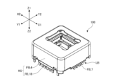
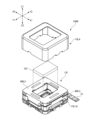
- FIG. 1 is a perspective view of the optical element driving device 100.
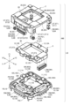
- FIG. FIG. 2 is an exploded perspective view of the optical element driving device 100 composed of the case 4 and the lower member LB, showing a state where the case 4 is separated from the lower member LB.
- FIG. 3 is an exploded perspective view of the lower member LB, showing a state where the movable member MB is separated from the fixed member FB.
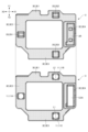
- FIG. 4 is a bottom view of the optical element holding member 2 constituting the optical element driving device 100.
- FIG. FIG. 5 is a bottom view of the intermediate member 3 constituting the optical element driving device 100.
- FIG. FIG. 6 is an exploded perspective view of the fixed member FB.
- a dot pattern is given to the optical element holding member 2 for clarity.
- the intermediate member 3 is marked with a dot pattern for clarity.
- X1 represents one direction of the X-axis forming the three-dimensional orthogonal coordinate system
- X2 represents the other direction of the X-axis
- Y1 represents one direction of the Y-axis forming the three-dimensional orthogonal coordinate system
- Y2 represents the other direction of the Y-axis
- Z1 represents one direction of the Z-axis forming the three-dimensional orthogonal coordinate system
- Z2 represents the other direction of the Z-axis.
- the X1 side of the optical element driving device 100 corresponds to the front side (front side) of the optical element driving device 100
- the X2 side of the optical element driving device 100 corresponds to the rear side (back side) of the optical element driving device 100.
- the Y1 side of the optical element driving device 100 corresponds to the left side of the optical element driving device 100
- the Y2 side of the optical element driving device 100 corresponds to the right side of the optical element driving device 100
- the Z1 side of the optical element driving device 100 corresponds to the upper side of the optical element driving device 100
- the Z2 side of the optical element driving device 100 corresponds to the lower side of the optical element driving device 100.
- the optical element driving device 100 is a device for moving the optical element OE as shown in FIG. 2 on a virtual plane parallel to the XY plane.
- the optical element OE is shown to have a substantially rectangular parallelepiped shape, but it may have other shapes such as a cylindrical shape.
- illustration of the optical element OE is omitted for clarity.
- the optical element OE is a lens body, mirror, prism, diffraction grating, light emitting element, light receiving element, imaging element, optical filter, or the like.
- the lens body is a cylindrical lens barrel with at least one lens.
- the optical element OE is a lens body. Therefore, hereinafter, the upper side of the optical element driving device 100 may be referred to as the "subject side", and the lower side of the optical element driving device 100 may be referred to as the "imaging device side".
- the optical element driving device 100 includes a case 4 and a lower member LB which are part of the fixed side member FB.
- the case 4 is a cover member that covers the lower member LB.
- the case 4 is produced by punching, drawing, and the like, on a plate material formed of non-magnetic metal such as austenitic stainless steel. Since the case 4 is made of non-magnetic metal, the case 4 does not magnetically affect the driving means DM (described later) that uses electromagnetic force.
- the case 4 has a lidded rectangular cylindrical outer shape that defines the storage portion 4S.
- the case 4 includes a substantially rectangular cylindrical outer wall portion 4A, and a substantially rectangular annular flat plate-shaped top plate portion provided so as to be continuous with the upper end (the end on the Z1 side) of the outer peripheral wall portion 4A. 4B and.
- a substantially rectangular through hole 4K is formed in the center of the top plate portion 4B.
- the outer peripheral wall portion 4A includes a first side plate portion 4A1 to a fourth side plate portion 4A4.
- the first side plate portion 4A1 and the third side plate portion 4A3 face each other, and the second side plate portion 4A2 and the fourth side plate portion 4A4 face each other.
- the second side plate portion 4A2 and the fourth side plate portion 4A4 extend perpendicularly to the first side plate portion 4A1 and the third side plate portion 4A3. Further, as shown in FIG. 1, the case 4 is joined to the base member 18 with an adhesive to form a housing HS together with the base member 18. As shown in FIG.
- the lower member LB includes, as shown in FIG. 3, a metal member 7, a magnetic member 13, a base member 18, a lower ball 11, and a movable member MB, which are part of the fixed member FB. .
- the lower ball 11 is configured to movably support the movable member MB in the direction parallel to the X-axis with respect to the fixed member FB.
- the lower balls 11 are spherical rolling elements made of a hard material such as resin, ceramic, or metal, and include first lower balls 11A to third lower balls 11C.
- the lower ball 11 includes a recess 18S (see FIG. 3) as a lower upward recess formed in the base member 18 and a recess 3S (see the upper diagram in FIG. 5) as a lower downward recess formed in the intermediate member 3. ) are placed between Specifically, the first lower ball 11A is arranged between the first recess 18S1 (see FIG.
- the second lower ball 11B is arranged between the second recess 18S2 (see FIG. 3) and the second recess 3S2 (see the upper diagram in FIG. 5).
- the third lower ball 11C is arranged between the third recess 18S3 (see FIG. 3) and the third recess 3S3 (see the upper diagram in FIG. 5).
- the coil 9 is a member fixed to the base member 18 .
- the coils 9 are wound type coils and include a first coil 9A and a second coil 9B.
- the coil 9 may be of the laminated type or of the film type.
- each of the first coil 9A and the second coil 9B may be configured by a combination of a plurality of coils.
- the magnetic member 13 is one of the members constituting the magnetic attracting means MA (described later), and is separated from the second driving magnet 5B and the attracting magnet 8, which are separate members constituting the magnetic attracting means MA. It is arranged so as to be magnetically attracted to the second driving magnet 5B and the attracting magnet 8, respectively.
- the magnetic member 13 includes a first magnetic member 13A, a second magnetic member 13B, and a third magnetic member 13C that are adhesively fixed to the upper surface of the base member 18 .
- the driving means DM includes a first driving means DM1 for moving the optical element OE along the X-axis direction and a second driving means DM2 for moving the optical element OE along the Y-axis direction.
- the first driving means DM1 includes a first coil 9A provided on the base member 18, and a first driving magnet 5A spaced apart so as to face the first coil 9A in the Z-axis direction.
- the second driving means DM2 includes a second coil 9B provided on the base member 18 and a second driving magnet 5B spaced apart so as to face the second coil 9B in the Z-axis direction.
- the optical element driving device 100 having a substantially rectangular parallelepiped shape is mounted on, for example, a main substrate (not shown).
- the coil 9 is connected to a current supply source through the metal member 7 and the main substrate.
- the driving means DM When the coil 9 is energized, the driving means DM generates an electromagnetic force along a direction parallel to the XY plane.
- the optical element driving device 100 utilizes the electromagnetic force generated by the driving means DM along the direction parallel to the XY plane to move the optical element OE along the direction parallel to the XY plane.
- a shift function (camera shake correction function) can be realized by moving the lens body as .
- the movable side member MB includes an optical element holding member 2, an intermediate member 3, a driving magnet 5, a detecting magnet 6, an attracting magnet 8, and an upper ball 12, as shown in FIG. .
- the driving magnet 5 includes a first driving magnet 5A and a second driving magnet 5B.
- each of the first driving magnet 5A and the second driving magnet 5B is a rectangular parallelepiped permanent magnet magnetized to two poles, the inner side being magnetized to the S pole, and the outer side being the N pole. is magnetized.
- FIG. 3 shows the portion magnetized to the N pole by a dot pattern. The same applies to the detection magnet 6 and the attraction magnet 8 .
- the first driving magnet 5A is arranged apart from the first coil 9A so as to face the first coil 9A in the Z-axis direction.
- the second driving magnet 5B is arranged apart from the second coil 9B so as to face the second coil 9B in the Z-axis direction.
- Each of the first driving magnet 5A and the second driving magnet 5B may be magnetized with an N pole on the inner side and an S pole on the outer side.
- each of the first driving magnet 5A and the second driving magnet 5B may be composed of a combination of a plurality of permanent magnets.
- the second driving magnet 5B is one of the members constituting the magnetic attraction means MA.
- the second driving magnet 5B is fixed to the optical element holding member 2 so that a magnetic attractive force acts between the second driving magnet 5B and the magnetic member 13 .
- the second driving magnet 5B is arranged apart from the third magnetic member 13C so as to face the third magnetic member 13C in the Z-axis direction.
- the third magnetic member 13C is arranged below the second coil 9B (Z2 side).
- the detection magnet 6 is a member for detecting displacement of the optical element OE.
- the detection magnet 6 includes a first detection magnet 6A for detecting displacement of the optical element OE in the X-axis direction and a second detection magnet 6A for detecting displacement of the optical element OE in the Y-axis direction. and a magnet 6B.
- each of the first detection magnet 6A and the second detection magnet 6B is a rectangular parallelepiped permanent magnet magnetized to two poles.
- the first detection magnet 6A is magnetized with two poles in the X-axis direction
- the second detection magnet 6B is magnetized with two poles in the Y-axis direction.
- the first detection magnet 6A and the second detection magnet 6B are fixed to the optical element holding member 2. As shown in FIG.
- the first detection magnet 6A is arranged apart from the first magnetic sensor 10A so as to face the first magnetic sensor 10A in the Z-axis direction.
- the second detection magnet 6B is arranged apart from the second magnetic sensor 10B so as to face the second magnetic sensor 10B in the Z-axis direction.
- Each of the first detection magnet 6A and the second detection magnet 6B may be composed of a plurality of permanent magnets.
- the attraction magnet 8 is one of the members that constitute the magnetic attraction means MA.
- the attraction magnet 8 is fixed to the optical element holding member 2 so that a magnetic attraction force acts between the attraction magnet 8 and the magnetic member 13 .
- the attracting magnet 8 includes a first attracting magnet 8A that is arranged away from the first magnetic member 13A so as to face the first magnetic member 13A in the Z-axis direction, and and a second attracting magnet 8B that is spaced apart from the second magnetic member 13B so as to face the second magnetic member 13B.
- the upper ball 12 is configured to movably support the optical element holding member 2 in the direction parallel to the Y-axis with respect to the intermediate member 3 .
- the upper balls 12 are spherical rolling elements made of a hard material such as resin, ceramic, or metal, and include first upper balls 12A to third upper balls 12C.
- the upper ball 12 includes a concave portion 3T (see FIG. 3) as an upper upward concave portion formed in the intermediate member 3 and a concave portion 2S (see the upper diagram in FIG. 4) as an upper downward concave portion formed in the optical element holding member 2. is placed between Specifically, the first upper ball 12A is arranged between the first recess 3T1 (see FIG.
- the second upper ball 12B is arranged between the second recess 3T2 (see FIG. 3) and the second recess 2S2 (see the upper diagram in FIG. 5).
- the third upper ball 12C is arranged between the third recess 3T3 (see FIG. 3) and the third recess 2S3 (see the upper diagram in FIG. 5).
- the optical element holding member 2 is configured to hold the optical element OE and the second driving magnet 5B.
- the optical element holding member 2 is formed by injection molding synthetic resin such as liquid crystal polymer (LCP).
- the optical element holding member 2 includes a through hole 2K formed so as to extend parallel to the Z axis, as shown in FIG.
- the optical element OE is fixed with an adhesive to the inner peripheral surface of the through hole 2K.
- FIG. 4 is a bottom view of the optical element holding member 2.
- FIG. Specifically, the upper diagram of FIG. 4 is a bottom view of the optical element holding member 2 when the second driving magnet 5B, the detecting magnet 6, the attracting magnet 8, and the upper ball 12 are not arranged.
- 4 is a bottom view of the optical element holding member 2 when the second driving magnet 5B, the detecting magnet 6, the attracting magnet 8, and the upper ball 12 are arranged.
- the optical element holding member 2 is a substantially rectangular annular frame.
- the four side portions 2E forming the frame include a first side portion 2E1 to a fourth side portion 2E4.
- a recess 2P recessed in the Z1 direction is provided on the end surface of the optical element holding member 2 on the lower side (Z2 side) on the imaging element side, as shown in the upper diagram of FIG.
- a detection magnet 6 is accommodated in the concave portion 2P as shown in the lower diagram of FIG.
- the detection magnet 6 is fixed to the optical element holding member 2 with an adhesive.
- the recess 2P includes a first recess 2P1 that accommodates the first detection magnet 6A and a second recess 2P2 that accommodates the second detection magnet 6B.
- the first recess 2P1 is provided at a first corner 2C1, which is one of the four corners 2C of the optical element holding member 2, and the second recess 2P2 is provided at the four corners 2C of the optical element holding member 2. It is provided at the second corner 2C2, which is another one of the corners.
- a recess 2Q recessed in the Z1 direction is provided on the end surface of the optical element holding member 2 on the lower side (Z2 side).
- the recess 2Q accommodates an attracting magnet 8.
- the attracting magnet 8 is fixed to the optical element holding member 2 with an adhesive.
- the recessed portion 2Q includes a first recessed portion 2Q1 in which the first attracting magnet 8A is accommodated, and a second recessed portion 2Q2 in which the second attracting magnet 8B is accommodated.
- the first concave portion 2Q1 is provided at a fourth corner portion 2C4, which is one of the four corner portions 2C of the optical element holding member 2, and the second concave portion 2Q2 is provided at the four corner portions 2C of the optical element holding member 2. It is provided at the third corner 2C3, which is another one of them.
- a recess 2R recessed in the Z1 direction is provided on the end face on the lower side (Z2 side) of the first side portion 2E1.
- the recess 2R accommodates the second driving magnet 5B.
- the second driving magnet 5B is fixed to the optical element holding member 2 with an adhesive. Note that the recess 2R may open not only downward but also laterally (outward in the radial direction).
- a concave portion 2S as an upper downward concave portion concaved in the Z1 direction is provided on the end surface of the optical element holding member 2 on the lower side (Z2 side).
- the concave portion 2S accommodates the upper portion of the upper ball 12, as shown in the lower diagram of FIG.
- the recess 2S includes a first recess 2S1 that accommodates the upper portion of the first upper ball 12A, a second recess 2S2 that accommodates the upper portion of the second upper ball 12B, and a third upper ball 12C. and a third recess 2S3 in which the upper part is accommodated.
- the first recessed portion 2S1 is provided on the lower (Z2 side) end surface of the third side portion 2E3
- the second recessed portion 2S2 is provided on the lower (Z2 side) end surface of the second side portion 2E2
- the third recessed portion 2S3 is provided on the end face on the lower side (Z2 side) of the fourth side portion 2E4.
- the lower portions of the first upper ball 12A to the third upper ball 12C are accommodated in recesses 3T (see FIG. 3) formed in the upper surface of the intermediate member 3 as upper upward recesses.
- At least one of the recess 2P, the recess 2R, and the recess 2Q may be a through hole extending parallel to the Z-axis.
- the intermediate member 3 is configured to hold the first driving magnet 5A.
- the intermediate member 3 is formed by injection molding synthetic resin such as liquid crystal polymer (LCP).
- LCP liquid crystal polymer
- the intermediate member 3 includes a through hole 3K formed so as to extend parallel to the Z-axis, as shown in FIG.
- the through hole 3K corresponds to the through hole 2K of the optical element holding member 2.
- the optical element OE is held by the optical element holding member 2 so as not to come into contact with the inner peripheral surface of the through hole 3K even when the optical element holding member 2 moves with respect to the intermediate member 3 .
- FIG. 5 is a bottom view of the intermediate member 3.
- the upper diagram of FIG. 5 is a bottom view of the intermediate member 3 when the first driving magnet 5A and the lower ball 11 are not arranged
- the lower diagram of FIG. 5 is the first driving magnet.
- 5A is a bottom view of the intermediate member 3 when 5A and the lower ball 11 are arranged.
- the intermediate member 3 is a substantially rectangular annular frame.
- the four side portions 3E forming the frame include a first side portion 3E1 to a fourth side portion 3E4.
- a recess 3R recessed in the Z1 direction is provided on the end surface of the intermediate member 3 on the lower side (Z2 side) on the imaging device side, as shown in the upper diagram of FIG. As shown in the lower diagram of FIG. 5, the recess 3R accommodates the first driving magnet 5A.
- the first driving magnet 5A is fixed to the intermediate member 3 with an adhesive. Note that the recess 3R may open not only downward but also laterally (outward in the radial direction).
- a concave portion 3S is provided on the lower side (Z2 side) of the intermediate member 3 as a downward concave portion that is concave in the Z1 direction.
- the concave portion 3S accommodates the upper portion of the lower ball 11, as shown in the lower diagram of FIG.
- the recessed portion 3S includes a first recessed portion 3S1 that accommodates the upper portion of the first lower ball 11A, a second recessed portion 3S2 that accommodates the upper portion of the second lower ball 11B, and a third lower portion. and a third recess 3S3 in which the upper portion of the ball 11C is accommodated.
- the first recessed portion 3S1 is provided on the lower (Z2 side) end surface of the second side portion 3E2
- the second recessed portion 3S2 is provided on the lower (Z2 side) end surface of the first side portion 3E1
- the third recessed portion 3S3 is provided on the end face on the lower side (Z2 side) of the third side portion 3E3.
- the lower portions of the first lower ball 11A to the third lower ball 11C are accommodated in recesses 18S (see FIG. 3) formed in the upper surface of the base member 18 as lower upward recesses.
- the recess 3R may be a through hole extending parallel to the Z-axis.
- the base member 18 is formed by injection molding using synthetic resin such as liquid crystal polymer.
- the base member 18 has a substantially rectangular profile when viewed from above, and has a through hole 18K in the center.
- the coil 9, the magnetic sensor 10, and the magnetic member 13 are fixed with an adhesive to the upper surface of the base member 18, which is the object-side surface (Z1-side surface).
- the through holes 18K correspond to the through holes 2K of the optical element holding member 2 and the through holes 3K of the intermediate member 3, respectively.
- a concave portion 18 ⁇ /b>B for accommodating the magnetic sensor 10 is formed on the upper surface of the base member 18 .
- the recess 18B includes a first recess 18B1 that houses the first magnetic sensor 10A and a second recess 18B2 that houses the second magnetic sensor 10B. Further, a concave portion 18U for accommodating the magnetic member 13 is formed on the upper surface of the base member 18. As shown in FIG. The recess 18U includes a first recess 18U1 that houses the first magnetic member 13A, a second recess 18U2 that houses the second magnetic member 13B, and a third recess 18U3 that houses the third magnetic member 13C. Further, a convex portion 18P to which the coil 9 is fixed is formed on the upper surface of the base member 18. As shown in FIG. The convex portion 18P includes a first convex portion 18P1 to which the first coil 9A is fixed and a second convex portion 18P2 to which the second coil 9B is fixed.
- the magnetic sensor 10 is configured to detect the position of the optical element OE.
- a plurality of magnetic sensors 10 are provided so as to detect the displacement in the X-axis direction and the displacement in the Y-axis direction of the optical element holding member 2 to which the optical element OE is fixed.
- the magnetic sensor 10 includes a first magnetic sensor 10A and a second magnetic sensor 10B.
- the magnetic sensor 10 is housed in the recess 18B with each of its four terminals connected to the metal member 7 .
- the first magnetic sensor 10A is housed in the first recess 18B1
- the second magnetic sensor 10B is housed in the second recess 18B2.
- the magnetic sensor 10 is configured by a Hall element, and by measuring the output voltage of the Hall element that changes according to the magnitude of the magnetic field from the detection magnet 6 received by the Hall element, It is configured to be able to detect the position of the movable side member MB including the magnet 6 .
- the magnetic sensor 10 is a giant magneto-resistive effect (GMR) element, a semiconductor magneto-resistive (SMR) element, an anisotropic magneto-resistive (AMR) element, or a tunnel magneto-resistive (AMR) element. It may be configured to detect the position of the optical element OE using a magnetoresistive element such as a Tunnel Magneto Resistive (TMR) element.
- TMR Tunnel Magneto Resistive
- the upper surface of the base member 18 is formed with a concave portion 18S as a lower upward concave portion that accommodates the lower ball 11 .
- the base member 18 has three recesses 18S (first recess 18S1 to third recess 18S1) for accommodating the three lower balls 11 (first lower ball 11A to third lower ball 11C). 18S3) are formed.
- the metal member 7 is a member that is embedded in the base member 18, and is configured so as to enable electrical connection between the coil 9 and the magnetic sensor 10 and the outside.
- the metal member 7 is made of non-magnetic metal.
- 6 is a perspective view of the metal member 7 and the base member 18. FIG. Specifically, FIG. 6 shows the relationship between the metal member 7 not embedded in the base member 18 and the coil 9 and magnetic sensor 10 fixed to the base member 18 .
- the metal member 7 and each of the coil 9 and the magnetic sensor 10 are joined together by solder, a conductive adhesive, or the like.
- a dot pattern is attached to the joint portion of the metal member 7 for clarity.
- the metal member 7 includes a first metal member 7A to a twelfth metal member 7L, part of which is embedded in the base member 18 by insert molding.
- one end of the first coil 9A is joined to the second metal member 7B, and the other end of the first coil 9A is joined to the third metal member 7C.
- the first terminal of the first magnetic sensor 10A is joined to the fourth metal member 7D
- the second terminal of the first magnetic sensor 10A is joined to the fifth metal member 7E
- the third terminal of the first magnetic sensor 10A is It is joined to the sixth metal member 7F
- the fourth terminal of the first magnetic sensor 10A is joined to the seventh metal member 7G.
- One end of the second coil 9B is joined to the eighth metal member 7H, and the other end of the second coil 9B is joined to the ninth metal member 7I.
- the first terminal of the second magnetic sensor 10B is joined to the tenth metal member 7J
- the second terminal of the second magnetic sensor 10B is joined to the eleventh metal member 7K
- the third terminal of the second magnetic sensor 10B is The fourth terminal of the second magnetic sensor 10B is joined to the first metal member 7A.
- FIGS. 3 and 7 are trihedral views (a front view, a top view, and a right side view) of the magnetic system mounted on the optical element driving device 100 of FIG.
- a magnetic system is a system that uses magnetic force, and includes drive means DM, magnetic attraction means MA, and position detection means PD.
- the driving means DM is means for moving the optical element OE on the XY plane.
- the drive means DM includes a first drive means DM1 for moving the optical element OE along the X-axis direction and a second drive means DM2 for moving the optical element OE along the Y-axis direction.
- the first driving means DM1 includes a first driving coil 9A provided on the base member 18 and a first driving coil 9A arranged so as to face the first coil 9A in the Z-axis direction. and a magnet 5A. As shown in FIG. 7, the first driving magnet 5A and the first coil 9A are arranged to face each other with a small gap therebetween.
- the second driving means DM2 includes a second driving coil 9B provided on the base member 18 and a second driving coil 9B disposed apart from the second coil 9B in the Z-axis direction so as to face the second coil 9B. and a magnet 5B. As shown in FIG. 7, the second driving magnet 5B and the second coil 9B are arranged to face each other with a small gap therebetween.
- the intermediate member 3 (the first driving magnet 5A) is guided by the lower ball guide structure including the lower balls 11, which will be described later, and the base member. 18 backward (X2 direction).
- the intermediate member 3 (first driving magnet 5A) moves forward (toward the base member 18) while being guided by the lower ball guide structure. X1 direction).
- the Lorentz force acts on the charged particles moving in the conductive wire forming the first coil 9A fixed to the base member 18, and the reaction force moves the first driving magnet 5A backward or forward. is.
- the optical element holding member 2 (the second driving magnet 5B) is guided by an upper ball guide structure including the upper ball 12, which will be described later. , to the right (Y2 direction) with respect to the intermediate member 3 and the base member 18 .
- the optical element holding member 2 (the second driving magnet 5B) moves toward the intermediate member 3 and the base member 18 while being guided by the upper ball guide structure. to the left (Y1 direction).
- the Lorentz force acts on the charged particles moving in the conductive wire forming the second coil 9B fixed to the base member 18, and the reaction force moves the second driving magnet 5B rightward or leftward. This is because
- the position detection means PD is means for detecting the position of the optical element OE fixed to the optical element holding member 2 on a virtual plane parallel to the XY plane.
- the position detection means PD includes a first position detection means PD1 for detecting the position of the optical element OE in the X-axis direction and a second position detection means PD1 for detecting the position of the optical element OE in the Y-axis direction. means PD2.
- the first position detection means PD1 includes a first detection magnet 6A and a first magnetic sensor 10A which are arranged with a space therebetween in the vertical direction.
- the second position detection means PD2 includes a second detection magnet 6B and a second magnetic sensor 10B which are spaced apart from each other in the vertical direction.
- the magnetic attraction means MA is means for generating a force that attracts two members together in the vertical direction (Z-axis direction).
- the magnetic attraction means MA is configured to generate a force that attracts the optical element holding member 2 and the base member 18 to each other.
- the magnetic attracting means MA includes a second driving magnet 5B, an attracting magnet 8, and a magnetic member 13.
- the magnetic attraction means MA includes a first magnetic attraction means MA1, a second magnetic attraction means MA2, and a third magnetic attraction means MA3, as shown in FIG.
- the first magnetic attraction means MA1 is configured to exert a magnetic attraction force between the first attraction magnet 8A and the first magnetic member 13A which are arranged with a space therebetween in the vertical direction.
- the second magnetic attraction means MA2 is configured to exert a magnetic attraction force between the second attraction magnet 8B and the second magnetic member 13B which are spaced apart from each other in the vertical direction.
- the third magnetic attraction means MA3 is configured to exert a magnetic attraction force between the second driving magnet 5B and the third magnetic member 13C, which are spaced apart from each other in the vertical direction.
- the magnetic attraction means MA can attract the optical element holding member 2 and the base member 18 to each other. Specifically, the recess 2S formed in the lower surface of the optical element holding member 2 is pressed against the upper portion of the upper ball 12 whose lower portion is accommodated in the recess 3T formed in the upper surface of the intermediate member 3. . Also, the recess 3S formed in the lower surface of the intermediate member 3 is pressed against the upper portion of the lower ball 11 whose lower portion is accommodated in the recess 18S formed in the upper surface of the base member 18. As shown in FIG. Therefore, the magnetic attraction means MA can stably maintain the contact state between the optical element holding member 2 and the upper portion of the upper ball 12 and between the lower portion of the upper ball 12 and the intermediate member 3 . Further, the magnetic attraction means MA can stably maintain the contact between the intermediate member 3 and the upper portion of the lower ball 11 and the contact between the lower portion of the lower ball 11 and the base member 18 .
- each of the first upper ball 12A to the third upper ball 12C constituting the upper ball 12 is placed between the optical element holding member 2 and the intermediate member 3 in a rollable state in the Y-axis direction. is sandwiched. Therefore, the optical element holding member 2 can be translated along the Y-axis without rotating (tilting) about the X-axis and without rotating (tilting) about the Y-axis.
- each of the first lower ball 11A to the third lower ball 11C constituting the lower ball 11 is sandwiched between the intermediate member 3 and the base member 18 in a rollable state in the X-axis direction. It is Therefore, the intermediate member 3 can be translated along the X-axis without rotating (tilting) about the X-axis and without rotating (tilting) about the Y-axis.
- the distance between the centers of the attracting magnets 8B is the same. However, those distances are smaller than the distance between the center of the third magnetic member 13C and the center of the second driving magnet 5B in the Z-axis direction. This is because the magnetic force of the second driving magnet 5B is greater than the respective magnetic forces of the first attracting magnet 8A and the second attracting magnet 8B. That is, by adjusting the respective distances, the magnetic attraction forces generated by the first magnetic attraction means MA1, the second magnetic attraction means MA2, and the third magnetic attraction means MA3 are made to be approximately the same. is.
- FIG. 8 is a cross-sectional view of the ball containing structure.
- the upper left diagram of FIG. 8 shows cross sections of the intermediate member 3, the third lower ball 11C, and the base member 18 on an imaginary plane parallel to the YZ plane including the dashed line L1 in the lower diagram of FIG.
- the upper right diagram of FIG. 8 shows cross sections of the intermediate member 3, the second lower ball 11B, and the base member 18 on an imaginary plane parallel to the YZ plane including the dashed line L2 in the lower diagram of FIG.
- FIG. 8 shows cross sections of the optical element holding member 2, the intermediate member 3, and the third upper ball 12C on a virtual plane parallel to the XZ plane including the dashed line L3 in the lower diagram of FIG.
- the lower right diagram of FIG. 8 shows cross sections of the optical element holding member 2, the intermediate member 3, and the second upper ball 12B on a virtual plane parallel to the XZ plane including the dashed line L4 in the lower diagram of FIG.
- the ball housing structure is a structure that houses the ball.
- the ball housing structure is composed of a pair of wide grooves that do not restrict the moving direction of the ball and two pairs of narrow grooves that restrict the moving direction of the ball.
- the ball housing structure includes a lower ball housing structure that houses the lower ball 11 and an upper ball housing structure that houses the upper ball 12 .
- the lower ball housing structure is composed of a pair of wide grooves that do not restrict the moving direction of the lower ball 11 and two pairs of narrow grooves that restrict the moving direction of the lower ball 11 .
- the upper ball housing structure is composed of a pair of wide grooves that do not restrict the moving direction of the upper ball 12 and two pairs of narrow grooves that restrict the moving direction of the upper ball 12 .
- the ball guide structure is a structure that guides the moving direction of the ball.
- the ball guide structure includes a lower ball guide structure that guides movement of the lower ball 11 along the X-axis direction and an upper ball guide structure that guides movement of the upper ball 12 along the Y-axis direction. including.
- the lower ball guide structure is composed of two pairs of narrow grooves that restrict the movement direction of the lower balls 11
- the upper ball guide structure is composed of two pairs of narrow grooves that restrict the movement direction of the upper balls 12. It is composed of narrow grooves.
- the pair of wide grooves in the lower ball housing structure are, as shown in the upper left view of FIG. It is a combination with the downward third concave portion 3S3.
- both widths are formed to be larger than the diameter D3 of the third lower ball 11C.
- the width D1 of the bottom surface of the third recess 3S3 in the Y-axis direction and the width D2 of the bottom surface of the third recess 18S3 in the Y-axis direction are both larger than the diameter D3 of the third lower ball 11C. is formed as
- a pair of the two pairs of narrow grooves in the lower ball housing structure are, as shown in the upper right view of FIG. It is a combination with the second concave portion 3S2 formed on the lower surface of the lower side downward.
- Another pair (not shown) of the two pairs of narrow grooves in the lower ball housing structure are formed in the lower upward first concave portion 18S1 formed in the upper surface of the base member 18 and the lower surface of the intermediate member 3. It is a combination with the first concave portion 3S1 formed on the lower side downward.
- the first lower ball 11A contacts the first recess 3S1 at two points of contact and It is sandwiched between the first recess 18S1 and the first recess 3S1 so as to contact the first recess 18S1 at the contact.
- the width of the opening (open end) of the second recess 18S2 in the axial direction is formed to be larger than the diameter D13 of the second lower ball 11B.
- both the width D11 of the bottom surface of the second recess 3S2 in the Y-axis direction and the width D12 of the bottom surface of the second recess 18S2 in the Y-axis direction are smaller than the diameter D13 of the second lower ball 11B.
- both the second recess 3S2 and the second recess 18S2 are configured such that the distance between the two side surfaces facing each other in the Y-axis direction increases toward the open end (opening). The same is true for another pair (not shown) of the two pairs of narrow grooves in the lower ball receiving structure.
- the two pairs of narrow grooves in the lower ball housing structure i.e., the lower ball guide structure, allow the lower ball 11 to move along the X-axis direction while being restricted from moving along the Y-axis direction. be guided to do so.
- the pair of wide grooves in the upper ball housing structure as shown in the lower left view of FIG. It is a combination with the upper downward third concave portion 2S3.
- both the width D21 of the bottom surface of the third recess 2S3 in the X-axis direction and the width D22 of the bottom surface of the third recess 3T3 in the X-axis direction are set to be larger than the diameter D23 of the third upper ball 12C.
- the first upper ball 12A is in contact with the first recess 2S1 at two points of contact and It is sandwiched between the first recess 2S1 and the first recess 3T1 so as to be in contact with the first recess 3T1.
- the width of the opening (open end) of the second concave portion 3T2 in all directions is formed to be larger than the diameter D33 of the second upper ball 12B.
- the width D31 of the bottom surface of the second recess 2S2 in the X-axis direction and the width D32 of the bottom surface of the second recess 3T2 in the X-axis direction are both smaller than the diameter D33 of the second upper ball 12B.
- both the second recess 2S2 and the second recess 3T2 are configured such that the distance between the two side surfaces facing each other in the X-axis direction increases toward the open end (opening). The same is true for another pair (not shown) of the two pairs of narrow grooves in the upper ball receiving structure.
- the two pairs of narrow grooves in the upper ball housing structure i.e., the upper ball guide structure, allow the upper ball 12 to move along the Y-axis direction while being restricted from moving along the X-axis direction. be guided.
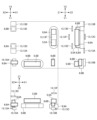
- FIG. 9 is a top view of the driving magnet 5, the attracting magnet 8, the lower ball 11, and the upper ball 12 that constitute the optical element driving device 100.
- FIG. 9 is a top view of the driving magnet 5, the attracting magnet 8, the lower ball 11, and the upper ball 12 that constitute the optical element driving device 100.
- a first triangle TR1 indicated by a dashed line is formed by connecting the center of the second driving magnet 5B and the centers of the two attracting magnets 8 (the first attracting magnet 8A and the second attracting magnet 8B). is a triangle.
- the center of each member is, for example, the center of gravity of each member. The same applies to the following description.
- a second triangle TR2 indicated by a dashed line is a triangle formed by connecting the respective centers of the three upper balls 12 (the first upper ball 12A, the second upper ball 12B, and the third upper ball 12C).
- the second triangle TR2 is oriented substantially opposite to the first triangle TR1.
- the first upper ball 12A is arranged between the first attracting magnet 8A and the second attracting magnet 8B.
- the second upper ball 12B is positioned outside the first triangle TR1 and arranged to face the first side TR1F of the first triangle TR1.
- the third upper ball 12C is positioned outside the first triangle TR1 and arranged to face the second side TR1S of the first triangle TR1.
- a third triangle TR3 indicated by a dashed line is a triangle formed by connecting the respective centers of the three lower balls 11 (the first lower ball 11A, the second lower ball 11B, and the third lower ball 11C). be.
- the third lower ball 11C is arranged between the first attracting magnet 8A and the second attracting magnet 8B.
- the first lower ball 11A is positioned outside the first triangle TR1 and is arranged to face the first side TR1F.
- the second lower ball 11B is positioned outside the first triangle TR1 and is arranged to face the second side TR1S.
- the point CG1 is the center of gravity of the first triangle TR1
- the point CG2 is the center of gravity of the second triangle TR2
- the point CG3 is the center of gravity of the third triangle TR3.
- the points CG1, CG2, and CG3 are all located within the area where the first triangle TR1, the second triangle TR2, and the third triangle TR3 overlap.
- a cross pattern is given to the overlapping region of the first triangle TR1, the second triangle TR2 and the third triangle TR3.
- the intermediate member 3 can rotate on the base member 18 via the three lower balls 11 around the three axes of the X, Y, and Z axes, and can rotate in the Y direction. And it is supported in a well-balanced manner so that it does not move in parallel in the Z-axis direction and can move in parallel in the X-axis direction.
- the optical element holding member 2 is arranged on the intermediate member 3 via the three upper balls 12 without rotating around the three axes of the X, Y, and Z axes, and rotating in the X and Z directions. It is supported in a well-balanced manner so that it can move in parallel in the Y-axis direction without moving in parallel in the Y-axis direction.
- FIG. 10 is a perspective view of the optical element driving device 100A and corresponds to FIG.
- FIG. 11 is an exploded perspective view of the optical element driving device 100A composed of the case 4 and the lower member LB, and shows a state in which the case 4 is separated from the lower member LB, corresponding to FIG. .
- FIG. 12 is an exploded perspective view of the lower member LB, showing a state in which the movable side member MB is separated from the fixed side member FB, and corresponds to FIG.
- FIG. 13 is a bottom view of the optical element holding member 2 that constitutes the optical element driving device 100A, and corresponds to FIG.
- FIG. 14 is a bottom view of the intermediate member 3 forming the optical element driving device 100A, and corresponds to FIG.
- FIG. 15 is a trihedral view (front view, top view, and right side view) of the magnetic system mounted on the optical element driving device 100A, and corresponds to FIG.
- FIG. 16 is a top view of the driving magnet 5, the attracting magnet 8, the lower ball 11, and the upper ball 12 that constitute the optical element driving device 100A, and corresponds to FIG.
- the optical element driving device 100A differs from the optical element driving device 100 in which the attracting magnet 8 is fixed to the optical element holding member 2 in that the attracting magnet 8 is fixed to the intermediate member 3 .
- the optical element driving device 100A As shown in FIG.
- the second attracting magnet 8B is housed in the second recess 3Q2, which is another one of the recesses 3Q formed in the lower surface of the second side portion 3E2 of the intermediate member 3.
- the first attracting magnet 8A is accommodated in the first concave portion 2Q1 formed at the fourth corner 2C4 of the optical element holding member 2
- the second attracting magnet 8A A magnet 8B is accommodated in a second recess 2Q2 formed in the third corner 2C3 of the optical element holding member 2.
- the optical element driving device 100A has six magnetic attraction means MA (first magnetic attraction means MA1 to sixth magnetic attraction means MA6). It differs from the optical element driving device 100 having three magnetic attraction means MA3). Therefore, in the optical element driving device 100A, the magnetic members 13 include first magnetic members 13A to third magnetic members 13A fixed to the base member 18, and fourth magnetic members 13D to 13D fixed to the optical element holding member 2. and a sixth magnetic member 13F.
- the first magnetic attraction means MA1 provides magnetic attraction between the first attraction magnet 8A and the first magnetic member 13A, which are arranged with a space therebetween in the vertical direction. It is configured to exert a suction force.
- the second magnetic attraction means MA2 is configured to exert a magnetic attraction force between the second attraction magnet 8B and the second magnetic member 13B which are spaced apart from each other in the vertical direction.
- the third magnetic attraction means MA3 is configured to exert a magnetic attraction force between the first driving magnet 5A and the third magnetic member 13C, which are arranged with a space therebetween in the vertical direction.
- the fourth magnetic attracting means MA4 consists of a first attracting magnet 8A spaced apart from each other in the vertical direction and a fourth magnetic member 13D provided on the lower surface of the optical element holding member 2 (see the lower diagram in FIG. 13). It is configured to exert a magnetic attraction force between.
- the fourth magnetic member 13D is accommodated in a first concave portion 2U1 (see the upper diagram of FIG. 13), which is one of the concave portions 2U formed in the lower surface of the second side portion 2E2 of the optical element holding member 2.
- the fifth magnetic attracting means MA5 consists of a second attracting magnet 8B spaced apart from each other in the vertical direction and a fifth magnetic member 13E provided on the lower surface of the optical element holding member 2 (see the lower diagram in FIG. 13). It is configured to exert a magnetic attraction force between.
- the fifth magnetic member 13E is accommodated in a second concave portion 2U2 (see the upper diagram in FIG. 13), which is another one of the concave portions 2U formed in the lower surface of the second side portion 2E2 of the optical element holding member 2. .
- the sixth magnetic attraction means MA6 consists of a first driving magnet 5A which is spaced apart from each other in the vertical direction and a sixth magnetic member 13F provided on the upper surface of the optical element holding member 2. It is configured to exert a magnetic attraction force between.
- the sixth magnetic member 13F is accommodated in a third recess 2U3 (see FIG. 12), which is another one of the recesses 2U formed in the upper surface of the fourth side portion 2E4 of the optical element holding member 2.
- the first attracting magnet 8A in the initial state is arranged so as to overlap the fourth magnetic member 13D in the vertical direction (Z-axis direction) as shown in FIG. It is arranged so as not to overlap with the first magnetic member 13A.
- the second attracting magnet 8B in the initial state is arranged so as to overlap the fifth magnetic member 13E in the vertical direction (Z-axis direction), as shown in FIG. are arranged so that they do not overlap.
- the initial state of the optical element driving device 100A means the state of the optical element driving device 100A when the coil 9 is not supplied with current.
- the first magnetic member 13A is arranged on the Y1 side (left side) of the first attracting magnet 8A by a predetermined distance
- the second magnetic member 13B is arranged in the Y-axis direction. , is arranged on the Y2 side (right side) of the second attracting magnet 8B by the same predetermined distance.
- This arrangement is such that the first attracting magnet 8A in the initial state overlaps the first magnetic member 13A in the vertical direction (Z-axis direction), and the second attracting magnet 8B in the initial state overlaps the vertical direction (Z-axis direction).
- the intermediate member 3 can be prevented from tilting about the first lower ball 11A more reliably than when the intermediate member 3 is arranged so as to overlap the second magnetic member 13B in the axial direction. This arrangement is because a force that attracts the intermediate member 3 and the base member 18 to each other can be applied at a position relatively far from the first lower ball 11A.
- the first attracting magnet 8A in the initial state is arranged so as to overlap the first magnetic member 13A in the vertical direction (Z-axis direction), and the second attracting magnet 8B in the initial state is arranged in the vertical direction (Z-axis direction). axial direction) so as to overlap the second magnetic member 13B.
- the sixth magnetic member 13F is attached to the upper surface of the optical element holding member 2, unlike the fourth magnetic member 13D and the fifth magnetic member 13E which are fixed to the lower surface of the optical element holding member 2. Fixed. That is, in the optical element driving device 100A, the distance between the center of the fourth magnetic member 13D and the center of the first attracting magnet 8A in the Z-axis direction, and the distance between the center of the fifth magnetic member 13E and the center of the first attraction magnet 8A in the Z-axis direction. The distances between the centers of the two attracting magnets 8B are the same, but the distances are greater than the distance between the center of the sixth magnetic member 13F and the center of the first driving magnet 5A in the Z-axis direction. small.
- the magnetic force of the first driving magnet 5A is greater than the magnetic force of each of the first attracting magnet 8A and the second attracting magnet 8B. That is, by adjusting the respective distances, the magnetic attraction forces generated by the fourth magnetic attraction means MA4, the fifth magnetic attraction means MA5, and the sixth magnetic attraction means MA6 are made approximately the same. is.
- a first triangle TR11 indicated by a dashed line is formed by connecting the center of the first driving magnet 5A and the centers of the two attracting magnets 8 (the first attracting magnet 8A and the second attracting magnet 8B). is a triangle.
- a second triangle TR12 indicated by a dashed line is a triangle formed by connecting the respective centers of the three upper balls 12 (the first upper ball 12A, the second upper ball 12B, and the third upper ball 12C).
- the first upper ball 12A is located outside the first triangle TR11 and arranged to face the first side TR11F, which is one side of the first triangle TR11.
- the third upper ball 12C is positioned outside the first triangle TR11 and arranged to face the second side TR11S, which is the other side of the first triangle TR11.
- the second upper ball 12B is positioned on an extension line of a virtual line TR11T connecting the center of the first attracting magnet 8A and the center of the second attracting magnet 8B. It is located laterally (to the right).
- a third triangle TR13 indicated by a dashed line is a triangle formed by connecting the respective centers of the three lower balls 11 (the first lower ball 11A, the second lower ball 11B, and the third lower ball 11C). be.
- the third triangle TR13 is oriented substantially opposite to the first triangle TR11.
- the first lower ball 11A is arranged between the first attracting magnet 8A and the second attracting magnet 8B.
- the third lower ball 11C is positioned outside the first triangle TR11 and is arranged to face the first side TR11F.
- the second lower ball 11B is positioned outside the first triangle TR11 and is arranged to face the second side TR11S.
- the point CG11 is the center of gravity of the first triangle TR11
- the point CG12 is the center of gravity of the second triangle TR12
- the point CG13 is the center of gravity of the third triangle TR13.
- the point CG11, the point CG12, and the point CG13 are all located within the area where the second triangle TR12 and the third triangle TR13 overlap.
- a cross pattern is given to the overlapping region of the second triangle TR12 and the third triangle TR13.
- the intermediate member 3 can rotate on the base member 18 via the three lower balls 11 around the three axes of the X, Y, and Z axes, and can rotate in the Y direction. And it is supported in a well-balanced manner so that it does not move in parallel in the Z-axis direction and can move in parallel in the X-axis direction.
- the optical element holding member 2 is arranged on the intermediate member 3 via the three upper balls 12 without rotating around the three axes of the X, Y, and Z axes, and rotating in the X and Z directions. It is supported in a well-balanced manner so that it can move in parallel in the Y-axis direction without moving in parallel in the Y-axis direction.
- FIG. 17 is a perspective view of the optical element driving device 100B and corresponds to FIG.
- FIG. 18 is an exploded perspective view of the optical element driving device 100B composed of the case 4 and the lower member LB, and shows a state where the case 4 is separated from the lower member LB, corresponding to FIG. .
- FIG. 19 is an exploded perspective view of the lower member LB, showing a state in which the movable member MB is separated from the fixed member FB, and corresponds to FIG.
- FIG. 20 is a bottom view of the optical element holding member 2 constituting the optical element driving device 100B, and corresponds to FIG. FIG.
- FIG. 21 is a bottom view of the intermediate member 3 forming the optical element driving device 100B, and corresponds to FIG.
- FIG. 22 is a trihedral view (front view, top view, and right side view) of the magnetic system mounted on the optical element driving device 100B, and corresponds to FIG.
- the optical element driving device 100B is different from the optical element driving device 100 in that the metal member 7, the attracting magnet 8, and the magnetic member 13 are omitted, and instead the magnetic member 14, the insulating substrate 15, and the magnetic member 16 are included. different.
- the magnetic member 14 and the magnetic member 16 are members constituting the magnetic attraction means MA, and are separated from the drive magnet 5 and the detection magnet 6, which are separate members constituting the magnetic attraction means MA. It is arranged so as to be magnetically attracted to each of the drive magnet 5 and the detection magnet 6 .
- the magnetic member 14 includes a first magnetic member 14A, a second magnetic member 14B, a third magnetic member 14C, and a fourth magnetic member 14D that are adhesively fixed to the upper surface of the optical element holding member 2 .
- the second magnetic member 14B and the fourth magnetic member 14D do not constitute the magnetic attraction means MA.
- the magnetic member 16 is embedded in the base member 18 by insert molding so that the upper surface is exposed.
- the magnetic member 16 is provided with a dot pattern for clarity.
- the insulating substrate 15 is a substrate on which a conductive pattern is formed.
- the insulating substrate 15 may be any of a flexible printed circuit board, a rigid printed circuit board, and a flexible rigid printed circuit board.
- the coil 9 and the magnetic sensor 10 are mounted on the insulating substrate 15 .
- the first detection magnet 6A is provided in the intermediate member 3 and the second detection magnet 6B is provided in the optical element holding member 2. It is different from the optical element driving device 100 in which the second detection magnet 6B is provided on the optical element holding member 2 .
- the second detection magnet 6B is accommodated in the concave portion 2P formed in the lower surface of the first side portion 2E1 of the optical element holding member 2.
- the first detection magnet 6A is accommodated in a recess 3P formed in the lower surface of the second side portion 3E2 of the intermediate member 3.
- the first detection magnet 6A is accommodated in the first concave portion 2P1 formed in the first corner portion 2C1 of the optical element holding member 2
- a magnet 6B is housed in a second recess 2P2 formed in the second corner 2C2 of the optical element holding member 2.
- FIG. 20 the second detection magnet 6B is accommodated in the concave portion 2P formed in the lower surface of the first side portion 2E1 of the optical element holding member 2.
- the first detection magnet 6A is accommodated in a recess 3P formed in the lower surface of the second side portion 3E2 of the intermediate member 3.
- the first detection magnet 6A is accommodated in the first concave portion 2P1 formed in the first corner portion 2C1
- the optical element driving device 100B has six magnetic attraction means MA (first magnetic attraction means MA1 to sixth magnetic attraction means MA6). It differs from the optical element driving device 100 having three magnetic attraction means MA3).
- the first magnetic attraction means MA1 generates a magnetic attraction force between the first driving magnet 5A and the magnetic member 16, which are spaced apart from each other in the vertical direction. is configured to act.
- the second magnetic attraction means MA2 is configured to exert a magnetic attraction force between the second detection magnet 6B and the magnetic member 16 which are spaced apart from each other in the vertical direction.
- the third magnetic attraction means MA3 is configured to exert a magnetic attraction force between the first detection magnet 6A and the magnetic member 16 which are spaced apart from each other in the vertical direction.
- the fourth magnetic attraction means MA4 is configured to exert a magnetic attraction force between the second driving magnet 5B and the magnetic member 16 which are spaced apart from each other in the vertical direction.
- the fifth magnetic attraction means MA5 magnetically attracts the first driving magnet 5A and the first magnetic member 14A provided on the upper surface of the optical element holding member 2, which are arranged with a space therebetween in the vertical direction. configured to exert force.
- the sixth magnetic attraction means MA6 magnetically attracts between the first detection magnet 6A and the third magnetic member 14C provided on the upper surface of the optical element holding member 2, which are arranged with a space therebetween in the vertical direction. configured to exert force.
- the optical element driving device 100B includes four lower balls 11 (first lower ball 11A to fourth lower ball 11D) and four upper balls 12 (first upper ball 12A to fourth upper ball 12D). , and differs from the optical element driving device 100 including three lower balls 11 and three upper balls 12 .
- the lower portions of the first lower ball 11A to the fourth lower ball 11D are formed in the upper surface of the base member 18, respectively. 18S4, and the upper parts of the first lower ball 11A to the fourth lower ball 11D are respectively formed in the lower surface of the intermediate member 3 by the first recess 3S1 to the fourth recess 3S4 (see the upper diagram of FIG. 21). ) are housed in
- the lower portions of the first upper ball 12A to the fourth upper ball 12D are accommodated in the first recess 3T1 to the fourth recess 3T4 formed in the upper surface of the intermediate member 3, respectively.
- the upper parts of the first upper ball 12A to the fourth upper ball 12D are accommodated in the first recess 2S1 to the fourth recess 2S4 (see the upper diagram of FIG. 20) formed in the lower surface of the optical element holding member 2, respectively.
- the intermediate member 3 is configured to have a U shape in plan view, as shown in FIG. Specifically, the intermediate member 3 has three side portions 3E (a first side portion 3E1, a second side portion 3E2, and a fourth side portion 3E4), and the side portion on the Y1 side is notched to form a space. It is configured to be SP.
- FIG. 21 shows the space SP with a dashed line for clarity.
- the optical element driving device 100 has a fixed side member FB including a support member (base member 18) and an optical element OE, as shown in FIGS.
- An optical element holding member 2 having a possible through hole 2K penetrating in the vertical direction, and a support member (base member 18) provided between the optical element holding member 2 and the support member (base member 18) in the vertical direction (Z-axis direction).
- An intermediate member 3 movable in a first direction (X-axis direction) perpendicular to the vertical direction (Z-axis direction) with respect to the base member 18), and disposed between the support member (base member 18) and the intermediate member 3 at least three lower balls 11 arranged between the intermediate member 3 and the optical element holding member 2; at least three upper balls 12 arranged between the intermediate member 3 and the optical element holding member 2;
- a first driving means DM1 for moving in one direction (X-axis direction), and an optical element holding member 2 perpendicular to the vertical direction (Z-axis direction) with respect to the intermediate member 3 and perpendicular to the first direction (X-axis direction).
- a second drive means DM2 for moving in a second direction (Y-axis direction).
- the optical element holding member 2 is configured to be movable along a plane (XY plane) perpendicular to the vertical direction (Z-axis direction) with respect to the supporting member (base member 18).
- the first driving means DM1 includes a supporting member (base member 18) that faces the first driving magnet 5A provided in the intermediate member 3 and the first driving magnet 5A in the vertical direction (Z-axis direction).
- the second driving means DM2 has a second driving magnet 5B provided in the optical element holding member 2 and a second driving magnet 5B provided in the optical element holding member 2 in the vertical direction (Z-axis direction). 5B and a second coil 9B provided on the supporting member (base member 18) so as to face.
- the support member may be the case 4 . In this case, the upper ball is read as the lower ball, and the lower ball is read as the upper ball.
- the first driving magnet 5A is provided on the intermediate member 3. Therefore, even if the optical element holding member 2 moves in the second direction (Y-axis direction), the relative positional relationship between the first driving magnet 5A and the first coil 9A does not change. Therefore, this configuration can suppress a decrease in driving efficiency of the first driving means DM1.
- the intermediate member 3 moves in the first direction (X-axis direction)
- the relative positional relationship between the second driving magnet 5B and the second coil 9B changes.
- the optical element holding member 2 were to move in the second direction (Y-axis direction)
- the effect of the change on the second driving means DM2 would be When the relative positional relationship changes, the change has less influence on the first driving means DM1.
- the first driving means DM1 moves both the intermediate member 3 and the optical element holding member 2, whereas the second driving means DM2 moves only the optical element holding member 2. be. Further, in this configuration, the driving magnet 5 and the coil 9 face each other in the vertical direction (Z-axis direction). Therefore, this configuration can suppress the size of the optical element driving device 100 in plan view.
- the intermediate member 3 may have a concave portion 3R as a first accommodating portion with the support member (base member 18) side (lower side) opened.
- the first driving magnet 5A is arranged in the recess 3R and fixed to the intermediate member 3, as shown in the lower diagram of FIG.
- the optical element holding member 2 may have a concave portion 2R as a second accommodating portion with the support member (base member 18) side (lower side) opened. good.
- the second driving magnet 5B is arranged in the concave portion 2R and fixed to the optical element holding member 2, as shown in the lower diagram of FIG.
- each of the recesses 2R and 3R which are open downward, may be open laterally (outward in the radial direction) in addition to downward.
- This configuration brings about the effect that the holding of each of the first driving magnet 5A and the second driving magnet 5B is ensured.
- first driving magnet 5A and the second driving magnet 5B may be arranged at least partially in the same position in the vertical direction (Z-axis direction). That is, the first driving magnet 5A and the second driving magnet 5B are arranged so as to overlap each other by a distance DX in the vertical direction (Z-axis direction), as shown in the front view and right side view of FIG. good too.
- the first coil 9A and the second coil 9B can also be arranged at least partially at the same position in the vertical direction (Z-axis direction). That is, the first coil 9A and the second coil 9B may also be arranged so as to overlap each other by a predetermined distance in the vertical direction (Z-axis direction), as shown in the front view and right side view of FIG.
- This configuration has the effect of reducing the dimension of the optical element driving device 100 in the vertical direction.
- the optical element driving device 100 includes a magnetic attraction means MA that generates a force that attracts the optical element holding member 2 and the support member (base member 18) in the vertical direction (Z-axis direction).
- the magnetic attraction means MA is provided on the second driving magnet 5B provided on the optical element holding member 2, the attraction magnet 8 provided on the optical element holding member 2, and the supporting member (base member 18). It may have a magnetic member 13 attached to it.
- the magnetic member 13 may be provided on the supporting member (base member 18) so that the magnetic member 13 and the second driving magnet 5B and the attracting magnet 8 are attracted to each other.
- the lower ball 11 can be sandwiched between the intermediate member 3 and the base member 18 by magnetic force without using an urging member such as a leaf spring or coil spring, and the upper ball 12 can be held by the optical element holding member by magnetic force. 2 and the intermediate member 3 can be sandwiched.
- the optical element driving device 100 may have three upper balls 12 as shown in FIG.
- one of the three upper balls 12 (first upper ball 12A) is positioned between two attraction magnets 8 (first attraction magnet 8A and second attraction magnet 8B). may be placed.
- Another one of the three upper balls 12 (the second upper ball 12B) is located between the center of the second driving magnet 5B and the two attracting magnets 5B in a plan view along the vertical direction (Z-axis direction).
- first triangle TR1 formed by connecting the respective centers of the magnets 8 (the first attracting magnet 8A and the second attracting magnet 8B), and is located outside the center of the second driving magnet 5B and two It may be arranged so as to face the first side TR1F of the first triangle TR1 connecting the center of one of the attracting magnets 8 (the second attracting magnet 8B). Further, the remaining one (third upper ball 12C) of the three upper balls 12 is positioned outside the first triangle TR1 in a plan view along the vertical direction (X-axis direction), and is positioned outside the second triangle TR1. It may be arranged so as to face the second side TR1S of the first triangle TR1 connecting the center of the driving magnet 5B and the center of the other of the two attracting magnets 8 (the first attracting magnet 8A).
- the upper ball 12 is stably held between the optical element holding member 2 and the intermediate member 3 by three magnets (the second driving magnet 5B, the first attracting magnet 8A, and the second attracting magnet 8B). produce the effect of being able to
- the first triangle TR1 and the second triangle TR2 formed by connecting the centers of the three upper balls 12 are substantially opposite. This is because
- the optical element driving device 100 may also have three lower balls 11 as shown in FIG.
- one of the three lower balls 11 third lower ball 11C
- two attracting magnets 8 first attracting magnet 8A and second attracting magnet 8B
- the remaining one of the three lower balls 11 (the second lower ball 11B) is located outside the first triangle TR1 and faces the second side TR1S in a plan view along the vertical direction. may be arranged to
- This configuration allows the lower ball 11 to be stably held between the intermediate member 3 and the base member 18 by three magnets (the second driving magnet 5B, the first attracting magnet 8A, and the second attracting magnet 8B). effect.
- the three magnets are separated from each other by the three lower balls 11 (the first lower ball 11A, the second lower ball 11B, and the third lower ball 11C) arranged separately from each other. This is because it is sandwiched between the intermediate member 3 and the base member .
- the optical element driving device 100 may also include three lower balls 11 and three upper balls 12, as shown in FIG.
- the optical element driving device 100 is formed by connecting the center of the second driving magnet 5B and the centers of the two attracting magnets 8 (the first attracting magnet 8A and the second attracting magnet 8B).
- the center of gravity (point CG3) of the third triangle TR3 formed by connecting It may be configured to be positioned within (a cross-patterned region).
- the lower ball 11 and the upper ball 12 are connected to the optical element holding member 2 and the base member 18 by three magnets (the second driving magnet 5B, the first attracting magnet 8A, and the second attracting magnet 8B). It brings about an effect that it can be more stably clamped between.
- the three lower balls 11 and the three upper balls 12 are arranged at different positions in a plan view in the vertical direction (Z-axis direction). It may be configured to be
- This configuration has the effect of reducing the dimension of the optical element driving device 100 in the vertical direction (Z-axis direction) because the lower ball 11 and the upper ball 12 do not overlap in the vertical direction (Z-axis direction).
- the optical element holding member 2 may be formed in a frame shape having a first side portion 2E1, a second side portion 2E2, a third side portion 2E3, and a fourth side portion 2E4. good.
- the third side portion 2E3 is arranged to face the first side portion 2E1 across the through hole 2K, and the first side portion 2E1 has a second side portion extending in the first direction (X-axis direction).
- a driving magnet 5B may be arranged.
- One end (fourth corner 2C4) of the third side 2E3 is provided with one of the two attracting magnets 8 (first attracting magnet 8A).
- the other of the two attracting magnets 8 may be arranged at the triangular portion 2C3).
- a first detection magnet 6A is arranged at one end (first corner 2C1) of the first side 2E1, and a second detection magnet 6A is arranged at the other end (second corner 2C2) of the first side 2E1.
- a magnet 6B may be arranged.
- the first magnetic sensor 10A is provided on the support member (base member 18) so as to face the first detection magnet 6A in the vertical direction (Z-axis direction).
- the second magnetic sensor 10B may be provided on the support member (base member 18) so as to face the second detection magnet 6B.
- This configuration allows a plurality of magnets (second drive magnet 5B, first detection magnet 6A, second detection magnet 6B, first attraction magnet 8A, and second attraction magnet 8B) to be arranged in good balance. effect.
- the optical element driving device 100 may include a magnetic attraction means MA that generates a force that attracts the intermediate member 3 and the optical element holding member 2 with the upper ball 12 interposed therebetween.
- the magnetic attraction means MA may include an attraction magnet 8 provided on the optical element holding member 2 .
- the optical element driving device 100A may include magnetic attraction means MA for generating a force that attracts the intermediate member 3 and the optical element holding member 2 with the upper ball 12 therebetween.
- the magnetic attraction means MA may include an attraction magnet 8 provided on the intermediate member 3 .
- This configuration provides an effect that the upper ball 12 can be sandwiched between the optical element holding member 2 and the intermediate member 3 by magnetic force without using an urging member such as a leaf spring or coil spring.
- the optical element holding member 2 includes a first side portion 2E1 and a second side portion 2E1 facing each other across the through hole 2K, as shown in FIG. 4 or FIG.
- the width dimension W3 of the third side portion 2E3 in the direction (Y-axis direction) orthogonal to the direction (X-axis direction) in which the third side portion 2E3 extends is the width dimension W1 of the first side portion 2E1, It may be smaller than both the width dimension W2 of the second side portion 2E2 and the width dimension W4 of the fourth side portion 2E4. 5 or 14, the intermediate member 3 extends along the first side 2E1, the second side 2E2, and the fourth side 2E4 of the optical element holding member 2 in the vertical direction (Z-axis direction). You may have the 1st side part 3E1, the 2nd side part 3E2, and the 4th side part 3E4 which each oppose.
- the attracting magnets 8 may be provided on the second side portion 2E2 and the fourth side portion 2E4 of the optical element holding member 2, as shown in FIG. In the optical element driving device 100, the attracting magnet 8 may be provided on either one of the second side portion 2E2 and the fourth side portion 2E4 of the optical element holding member 2.
- FIG. For example, when the first direction in which the intermediate member 3 moves is defined as the Y-axis direction and the second direction in which the optical element holding member 2 moves is defined as the X-axis direction, the first driving magnet 5A is positioned in the intermediate direction.
- the second driving magnet 5B may be arranged on the fourth side portion 2E4 of the optical element holding member 2.
- the attracting magnet 8 is provided on the second side portion 2E2 of the optical element holding member 2.
- the optical element driving device 100 may be configured such that a magnetic attraction force is generated between the attraction magnet 8 and a magnetic member provided on the intermediate member 3 or the base member 18 .
- the attracting magnet 8 may be provided on the second side portion 3E2 of the intermediate member 3, as shown in FIG.
- the attracting magnets 8 may be provided on the second side portion 3E2 and the fourth side portion 3E4 of the intermediate member 3.
- the first direction in which the intermediate member 3 moves is defined as the Y-axis direction
- the first driving magnet 5A is arranged on the first side portion 3E1 of the intermediate member 3
- the second direction in which the optical element holding member 2 moves is
- the second driving magnet 5B may be arranged on the fourth side portion 2E4 of the optical element holding member 2 by defining the X-axis direction.
- the attraction magnets 8 may be provided on the second side portion 3E2 and the fourth side portion 3E4 of the intermediate member 3, respectively.
- the attracting magnet 8 may be provided on at least one of the second side portion 2E2 and the fourth side portion 2E4 of the optical element holding member 2.
- FIG. it is preferable that the second driving magnet 5B also constitutes the magnetic attraction means.
- the optical element OE driven by the optical element driving devices 100 and 100A and the Y2 side (right side) of the optical element driving devices 100 and 100A ) can reduce the distance to another device arranged adjacent to the device.
- the upper balls 12 are arranged on the first side portion 2E1, the second side portion 2E2, and the fourth side portion 2E4 of the optical element holding member 2.
- the second driving magnet 5B is provided on a side portion (first side portion 2E1) of the optical element holding member 2 different from the third side portion 2E3.
- the members (fourth magnetic member 13D to sixth magnetic member 13F) constituting the magnetic attracting means MA have side portions different from the third side portion 2E3 of the optical element holding member 2 (the second side portion 2E2 and the fourth side portion 2E4).
- the width dimension W3 of the third side portion 2E3 of the optical element holding member 2 can be further reduced.
- the effect is that the distance between another device arranged adjacent to (on the right) can be made even smaller.
- the second side portion 3E2 of the intermediate member 3 is provided with two attracting magnets 8 (a first attracting magnet 8A and a second attracting magnet 8A) separated from each other.
- the magnet 8B) may be fixed, and the first driving magnet 5A may be fixed to the fourth side portion 3E4 of the intermediate member 3.
- the magnetic attracting means MA includes two attracting magnets 8 (a first attracting magnet 8A and a second attracting magnet 8B), a first driving magnet 5A, and a magnetic member 13 ( The first magnetic member 13A to the sixth magnetic member 13F) may be included.
- the magnetic member 13 (fourth magnetic member 13D to sixth magnetic member 13F) has two attracting magnets 8 (first attracting magnet 8A and second attracting magnet 8B) in the vertical direction (Z-axis direction) and It may be fixed to the optical element holding member 2 so that an attractive force acts between each of the first driving magnets 5A and the magnetic members 13 (fourth magnetic members 13D to sixth magnetic members 13F).
- the three magnetic members 13 (fourth magnetic member 13D to sixth magnetic member 13F) may be composed of one or two magnetic members.
- the fourth magnetic member 13D and the fifth magnetic member 13E may be integrated as one magnetic member.
- This configuration provides an effect that the upper ball 12 can be more stably held between the optical element holding member 2 and the intermediate member 3 by magnetic forces generated at three locations.
- the optical element driving device 100A As shown in FIG. 14, two attracting magnets 8 (a first attracting magnet 8A and a second attracting magnet 8B) are fixed to the intermediate member 3 in a separated state. Moreover, the first driving magnet 5A may be fixed at a position separated from the two attracting magnets 8 (the first attracting magnet 8A and the second attracting magnet 8B).
- the magnetic attraction means MA (fourth magnetic attraction means MA4 to sixth magnetic attraction means MA6) includes two attraction magnets 8 (first attraction magnet 8A and second attraction magnet 8A). 8B), the first driving magnet 5A, and the magnetic member 13 (fourth magnetic member 13D to sixth magnetic member 13F).
- the magnetic member 13 (fourth magnetic member 13D to sixth magnetic member 13F) has two attracting magnets 8 (first attracting magnet 8A and second attracting magnet 8B) in the vertical direction (Z-axis direction) and It may be fixed to the optical element holding member 2 so that an attractive force acts between each of the first driving magnets 5A and the magnetic members 13 (fourth magnetic members 13D to sixth magnetic members 13F).
- the optical element driving device 100A includes another magnetic attraction means MA (first magnetic attraction means MA1 to second magnetic attraction means MA1) that generates a force that attracts the intermediate member 3 and the support member (base member 18) to each other with the lower ball 11 interposed therebetween.
- 3 magnetic attraction means MA3 may be provided.
- another magnetic attraction means MA (first magnetic attraction means MA1 to third magnetic attraction means MA3) includes, as shown in FIG. 8B), the first driving magnet 5A, and another magnetic member 13 (first magnetic member 13A to third magnetic member 13C). Further, another magnetic member 13 (first magnetic member 13A to third magnetic member 13C) has two attracting magnets 8 (first attracting magnet 8A and second attracting magnet 8B) in the vertical direction (Z-axis direction). ) and the first driving magnet 5A and another magnetic member 13 (first magnetic member 13A to third magnetic member 13C), fixed to the support member (base member 18) so that an attractive force acts between each of them. may have been
- the lower ball 11 is connected to the intermediate member 3 by another magnetic attraction means MA (first magnetic attraction means MA1 to third magnetic attraction means MA3) without using a biasing member such as a leaf spring or a coil spring. It brings about an effect that it can be sandwiched with the base member 18 . Further, in this configuration, the intermediate member 3 and the base member 18 are lowered by the magnetic force generated by each of the three magnets (the first driving magnet 5A, the first attracting magnet 8A, and the second attracting magnet 8B). This provides an effect that the side ball 11 can be stably held and the upper ball 12 can be stably held between the optical element holding member 2 and the intermediate member 3 .
- first magnetic attraction means MA1 to third magnetic attraction means MA3 without using a biasing member such as a leaf spring or a coil spring.
- each of the three magnets (the first driving magnet 5A, the first attracting magnet 8A, and the second attracting magnet 8B) is connected to the magnetic attraction means MA (fourth magnetic attraction means MA4 to sixth It is shared by the magnetic attraction means MA6) and another magnetic attraction means MA (first magnetic attraction means MA1 to third magnetic attraction means MA3). Therefore, this configuration brings about the effect of being able to reduce the number of parts.
- the optical element driving device 100A may also include three lower balls 11 (first lower ball 11A to third lower ball 11C), as shown in FIG.
- one of the three lower balls 11 (first lower ball 11A) is arranged between two attracting magnets 8 (first attracting magnet 8A and second attracting magnet 8B).
- the remaining one (second lower ball 11B) of the three lower balls 11 extends in the second direction (Y-axis direction) in a plan view along the vertical direction (Z-axis direction). It may be arranged so as to face the other end (the end on the Y2 side) of the first driving magnet 5A.
- This configuration allows the lower ball 11 to be stably held between the intermediate member 3 and the base member 18 by three magnets (the first driving magnet 5A, the first attracting magnet 8A, and the second attracting magnet 8B). effect.
- the optical element driving device 100A may also include three upper balls 12, as shown in FIG.
- one of the three upper balls 12 (the second upper ball 12B) has two attracting magnets 8 (the first attracting magnet 8A and It may be located on an extension line of the imaginary line TR11T connecting the centers of the second attracting magnets 8B), and may be arranged to the side (right side) of the attracting magnets 8 (second attracting magnets 8B).
- Another one of the three upper balls 12 (the first upper ball 12A) is located between the center of the first driving magnet 5A and the two attracting magnets in a plan view along the vertical direction (the Z-axis direction).
- first triangle TR11 Positioned outside a first triangle TR11 formed by connecting the respective centers of the magnets 8 (the first attracting magnet 8A and the second attracting magnet 8B), and the center of the first driving magnet 5A. and the center of one of the two attracting magnets 8 (the first attracting magnet 8A).
- the remaining one (third upper ball 12C) of the three upper balls 12 is positioned outside the first triangle TR11 in plan view along the vertical direction (Z-axis direction), and is positioned outside the first triangle TR11.
- a second side TR11S Arranged so as to face a second side TR11S, which is the other side of the first triangle TR11 connecting the center of the driving magnet 5A and the center of the other of the two attracting magnets 8 (the second attracting magnet 8B). may have been
- the upper ball 12 is stably held between the optical element holding member 2 and the intermediate member 3 by three magnets (the first driving magnet 5A, the first attracting magnet 8A, and the second attracting magnet 8B). produce the effect of being able to
- the three upper balls 12 (the first upper ball 12A, the second upper ball 12B, and the third upper ball 12C) distributed and spaced from each other are arranged to form an optical element by means of the three magnets distributed and spaced from each other. This is because it is sandwiched between the holding member 2 and the intermediate member 3 .
- the optical element driving device 100A may also include three lower balls 11 and three upper balls 12, as shown in FIG.
- the optical element driving device 100A is formed by connecting the center of the first driving magnet 5A and the centers of the two attracting magnets 8 (the first attracting magnet 8A and the second attracting magnet 8B). center of gravity of the first triangle TR11 (point CG11), the center of gravity of the second triangle TR12 formed by connecting the centers of the three upper balls 12 (point CG12), and the center of each of the three lower balls 11
- the lower balls 11 and the upper balls 12 that are appropriately distributed can support the intermediate member 3 in a well-balanced manner so that it can move in parallel on the base member 18 in the X-axis direction.
- the optical element driving device 100 may also include three lower balls 11 and three upper balls 12, as shown in FIG.
- the base member 18 as a support member may have three recesses 18S as upward recesses on the lower side, which are open at the top in which the lower balls 11 are arranged.
- the intermediate member 3 has three concave portions 3S (see the upper diagram of FIG. 5) which are open at the bottom where the lower balls 11 are arranged, and an open upper portion where the upper balls 12 are arranged. It may have recesses 3T as three upper upward recesses.
- the optical element holding member 2 may have recesses 2S (see the upper diagram of FIG. 4) as three upper downward recesses that are open at the bottom in which the upper balls 12 are arranged.
- One of the three recesses 18S (first recess 18S1) and one of the three recesses 3S (first recess 3S1) correspond to one of the three lower balls 11 (first lower ball). They may be arranged so as to face each other with the ball 11A) interposed therebetween.
- second recess 18S2 and another one of the three recesses 3S are different from the three lower balls 11. (second lower ball 11B).
- one of the three recessed portions 18S (first recessed portion 18S1), one of the three recessed portions 3S (first recessed portion 3S1), and another one of the three recessed portions 18S (second recessed portion 18S2) ) and another one (second recess 3S2) of the three recesses 3S are arranged downward so that the intermediate member 3 can move in the first direction (X-axis direction) with respect to the base member 18.
- a lower ball guide structure for guiding the balls 11 may be configured.
- each of the third recess 3S3 and the third recess 18S3 has a size (width D1 and width D2) in plan view that is equal to that of the lower ball 11 (third lower ball 11C). may be configured to be larger than the diameter D3.
- This configuration brings about the effect that the intermediate member 3 can be linearly moved in the first direction (X-axis direction) with respect to the base member 18 .
- One of the three recesses 3T (first recess 3T1) and one of the three recesses 2S (first recess 2S1) correspond to one of the three upper balls 12 (first upper ball). They may be arranged so as to face each other with the ball 12A) interposed therebetween.
- Another one of the three recesses 3T (the second recess 3T2) and another one of the three recesses 2S (the second recess 2S2) correspond to another one of the three upper balls 12. They may be arranged so as to face each other with one (second upper ball 12B) interposed therebetween.
- one of the three recessed portions 3T (first recessed portion 3T1), one of the three recessed portions 2S (first recessed portion 2S1), and another one of the three recessed portions 3T (second recessed portion 3T2 ) and another one of the three recesses 2S (second recess 2S2) are arranged so that the optical element holding member 2 can move in the second direction (Y-axis direction) with respect to the intermediate member 3.
- An upper ball guide structure that guides the upper ball 12 may be configured.
- the remaining one (third recess 3T3) of the three recesses 3T and the remaining one (third recess 2S3) of the three recesses 2S are the remaining recesses of the three upper balls 12. They may be arranged so as to face each other with one (third upper ball 12C) interposed therebetween. As shown in the lower left diagram of FIG. 8, each of the third recessed portion 3T3 and the third recessed portion 2S3 has a size (width D21 and width D22) in plan view that corresponds to the diameter of the upper ball 12 (third upper ball 12C). It may be configured to be larger than D23.
- This configuration brings about the effect that the optical element holding member 2 can be linearly moved in the second direction (Y-axis direction) with respect to the intermediate member 3 .
- the optical element holding member 2 includes a first side portion 2E1 and a third side portion 2E3 facing each other with the through hole 2K interposed therebetween.
- the intermediate member 3 faces the first side portion 2E1, the second side portion 2E2, and the fourth side portion 2E4 of the optical element holding member 2 in the vertical direction (Z-axis direction).
- the optical element holding member 2 has a first side portion 3E1, a second side portion 3E2, and a fourth side portion 3E4, and a portion facing the third side portion 2E3 of the optical element holding member 2 is cut out to form a substantially U-shape. may have.
- the second driving magnet 5B fixed to the optical element holding member 2 may be arranged in the notched portion (space SP) of the intermediate member 3 as shown in FIGS. 18 and 19 .
- This configuration has the effect of suppressing the size of the optical element driving device 100B in plan view. Specifically, this configuration brings about an effect that the width dimension of the optical element driving device 100B in the Y-axis direction can be reduced.
- the fixed side member FB may have a case 4 as a metal cover member forming a housing HS together with the base member 18, as shown in FIG.
- the intermediate member 3 and the optical element holding member 2 may be housed inside the housing HS.
- the optical element holding member 2 may be larger than the intermediate member 3 in plan view.
- the outer peripheral surface of the optical element holding member 2 is provided with a first contact surface that can come into contact with the inner surface of the case 4 when the optical element holding member 2 moves in the first direction (X-axis direction).
- the contact portion ST that constitutes the structure for limiting the movement range of the optical element holding member 2 includes a first contact portion ST1 and a second contact portion ST2.
- the first contact portion ST1 includes a first right front contact portion ST11 and a first left front contact portion ST12 formed on the front side (X1 side) side surface of the optical element holding member 2, and the optical element holding member 2. It includes a first left rear contact portion ST13 and a first right rear contact portion ST14 formed on the side surface on the rear side (X2 side).
- the second contact portion ST2 includes a second left front contact portion ST21 and a second left rear contact portion ST22 formed on the left (Y1 side) side surface of the optical element holding member 2, and the optical element holding member 2. a second right rear contact portion ST23 and a second right front contact portion ST24 formed on the right side (Y2 side) of the .
- This configuration brings about the effect that the movement range of the optical element holding member 2 can be restricted with a simple configuration. That is, this configuration brings about an effect that a stopper mechanism for the optical element holding member 2 can be realized with a simple configuration. Moreover, this configuration brings about an effect that the dimensional accuracy of the stopper mechanism can be easily improved compared to the configuration in which a part of the plurality of contact portions ST is provided on the intermediate member 3 . This is because the dimensional accuracy of the stopper mechanism can be increased simply by increasing the dimensional accuracy of the optical element holding member 2 .
- the first driving means DM1 is composed of one first driving magnet 5A and one first coil 9A. It may be composed of the first driving magnet 5A and the pair of first coils 9A. The same applies to the second driving means DM2.
- the intermediate member 3 is a rectangular annular member having four sides (first side 3E1 to fourth side 3E4) as shown in FIG. Like the device 100B, it may be a substantially U-shaped member (see FIG. 21) that does not have one side (third side 3E3).
- Magnetic sensor 10A First magnetic sensor 10B Second magnetic sensor 11 Lower ball 11A First lower ball 11B Second lower ball 11C Third lower Side ball 11D... 4th lower ball 12... Upper side ball 12A... 1st upper side ball 12B... 2nd upper side ball 12C... 3rd upper side ball 12D... 4th upper side ball 13 ... magnetic member 13A ... first magnetic member 13B ... second magnetic member 13C ... third magnetic member 13D ... fourth magnetic member 13E ... fifth magnetic member 13F ... third 6 Magnetic member 14... Magnetic member 14A... First magnetic member 14B... Second magnetic member 14C... Third magnetic member 14D... Fourth magnetic member 15...
- Insulating substrate 16 ... ⁇ Magnetic member 18...Base member 18B...Concave part 18B1...First concave part 18B2...Second concave part 18K...Through hole 18P...Convex part 18P1...First convex part 18P2- ... second convex portion 18S ... concave portion 18S1 ... first concave portion 18S2 ... second concave portion 18S3 ... third concave portion 18S4 ... fourth concave portion 18U ... concave portion 18U1 ...
- first Concave portion 18U2 Second concave portion 18U3 Third concave portion 100, 100A, 100B Optical element driving device CG1 to CG3, CG11 to CG13 Points CP1, CP2, CP11 to CP14, CP21, CP22, CP31 to CP34... Contacts DM... Drive means DM1... First drive means DM2... Second drive means FB... Fixed side member HS... Housing LB... Lower side member MA ... Magnetic attraction means MA1 ... First magnetic attraction means MA2 ... Second magnetic attraction means MA3 ... Third magnetic attraction means MA4 ... Fourth magnetic attraction means MA5 ...
Landscapes
- Physics & Mathematics (AREA)
- General Physics & Mathematics (AREA)
- Engineering & Computer Science (AREA)
- Multimedia (AREA)
- Signal Processing (AREA)
- Optics & Photonics (AREA)
- Adjustment Of Camera Lenses (AREA)
- Lens Barrels (AREA)
Priority Applications (2)
| Application Number | Priority Date | Filing Date | Title |
|---|---|---|---|
| CN202280074067.2A CN118215882A (zh) | 2021-12-15 | 2022-12-12 | 光学元件驱动装置 |
| JP2023567778A JP7666785B2 (ja) | 2021-12-15 | 2022-12-12 | 光学素子駆動装置 |
Applications Claiming Priority (2)
| Application Number | Priority Date | Filing Date | Title |
|---|---|---|---|
| JP2021203681 | 2021-12-15 | ||
| JP2021-203681 | 2021-12-15 |
Publications (1)
| Publication Number | Publication Date |
|---|---|
| WO2023112896A1 true WO2023112896A1 (ja) | 2023-06-22 |
Family
ID=86774711
Family Applications (1)
| Application Number | Title | Priority Date | Filing Date |
|---|---|---|---|
| PCT/JP2022/045698 Ceased WO2023112896A1 (ja) | 2021-12-15 | 2022-12-12 | 光学素子駆動装置 |
Country Status (3)
| Country | Link |
|---|---|
| JP (1) | JP7666785B2 (https=) |
| CN (1) | CN118215882A (https=) |
| WO (1) | WO2023112896A1 (https=) |
Cited By (2)
| Publication number | Priority date | Publication date | Assignee | Title |
|---|---|---|---|---|
| WO2025146015A1 (zh) * | 2024-01-02 | 2025-07-10 | 华为技术有限公司 | 马达、摄像模组以及电子设备 |
| JP2025533691A (ja) * | 2023-09-20 | 2025-10-09 | チャンジョウ エーエーシー レイテック オプトロニクス カンパニーリミテッド | 光学防振装置及び光学機器 |
Citations (5)
| Publication number | Priority date | Publication date | Assignee | Title |
|---|---|---|---|---|
| JP2008152034A (ja) * | 2006-12-18 | 2008-07-03 | Tamron Co Ltd | アクチュエータ、及びそれを備えたレンズユニット、カメラ |
| JP2008304850A (ja) * | 2007-06-11 | 2008-12-18 | Tamron Co Ltd | アクチュエータ、及びそれを備えたレンズユニット、カメラ |
| JP2011175036A (ja) * | 2010-02-23 | 2011-09-08 | Nittoh Kogaku Kk | 手振れ補正装置 |
| JP2017090887A (ja) * | 2015-11-13 | 2017-05-25 | サムソン エレクトロ−メカニックス カンパニーリミテッド. | レンズ駆動装置及びそれを含むカメラモジュール |
| JP2020177252A (ja) * | 2014-11-14 | 2020-10-29 | エルジー イノテック カンパニー リミテッド | レンズ駆動装置 |
-
2022
- 2022-12-12 JP JP2023567778A patent/JP7666785B2/ja active Active
- 2022-12-12 CN CN202280074067.2A patent/CN118215882A/zh active Pending
- 2022-12-12 WO PCT/JP2022/045698 patent/WO2023112896A1/ja not_active Ceased
Patent Citations (5)
| Publication number | Priority date | Publication date | Assignee | Title |
|---|---|---|---|---|
| JP2008152034A (ja) * | 2006-12-18 | 2008-07-03 | Tamron Co Ltd | アクチュエータ、及びそれを備えたレンズユニット、カメラ |
| JP2008304850A (ja) * | 2007-06-11 | 2008-12-18 | Tamron Co Ltd | アクチュエータ、及びそれを備えたレンズユニット、カメラ |
| JP2011175036A (ja) * | 2010-02-23 | 2011-09-08 | Nittoh Kogaku Kk | 手振れ補正装置 |
| JP2020177252A (ja) * | 2014-11-14 | 2020-10-29 | エルジー イノテック カンパニー リミテッド | レンズ駆動装置 |
| JP2017090887A (ja) * | 2015-11-13 | 2017-05-25 | サムソン エレクトロ−メカニックス カンパニーリミテッド. | レンズ駆動装置及びそれを含むカメラモジュール |
Cited By (2)
| Publication number | Priority date | Publication date | Assignee | Title |
|---|---|---|---|---|
| JP2025533691A (ja) * | 2023-09-20 | 2025-10-09 | チャンジョウ エーエーシー レイテック オプトロニクス カンパニーリミテッド | 光学防振装置及び光学機器 |
| WO2025146015A1 (zh) * | 2024-01-02 | 2025-07-10 | 华为技术有限公司 | 马达、摄像模组以及电子设备 |
Also Published As
| Publication number | Publication date |
|---|---|
| JPWO2023112896A1 (https=) | 2023-06-22 |
| JP7666785B2 (ja) | 2025-04-22 |
| CN118215882A (zh) | 2024-06-18 |
Similar Documents
| Publication | Publication Date | Title |
|---|---|---|
| US12372758B2 (en) | Rotational ball-guided voice coil motor | |
| US9904072B2 (en) | Lens driving device | |
| JP7666785B2 (ja) | 光学素子駆動装置 | |
| KR102632373B1 (ko) | 센서 시프팅 액추에이터 및 이를 포함하는 카메라 모듈 | |
| US12238419B2 (en) | Sensor shifting module and camera module including the same | |
| JP2021535425A (ja) | イメージの解像度を向上させるための、または、スペックル・ノイズを低減させるための光学デバイス | |
| JP7108589B2 (ja) | レンズ駆動装置、カメラ装置及び電子機器 | |
| JP7826590B2 (ja) | 光学素子駆動装置 | |
| CN213276093U (zh) | 光学部件驱动装置、照相装置以及电子设备 | |
| CN119986939A (zh) | 光学元件驱动机构 | |
| WO2022181640A1 (ja) | 反射体駆動装置 | |
| US12411303B2 (en) | Lens holder driving apparatus | |
| KR102632375B1 (ko) | 센서 시프팅 액추에이터 | |
| CN100369129C (zh) | 物镜驱动装置 | |
| CN112987450B (zh) | 光学部件驱动装置、照相装置以及电子设备 | |
| JP2024076239A (ja) | 光学素子駆動装置 | |
| CN115390208A (zh) | 光学单元以及智能手机 | |
| JP2023031797A (ja) | 光学ユニット及び光学ユニットの製造方法 | |
| JP7628571B2 (ja) | 光学部材駆動装置、カメラ装置及び電子機器 | |
| JP4404364B2 (ja) | 磁気式加速度センサを用いた小型の加速度地磁気検出装置 | |
| JP2003257056A (ja) | レンズアクチュエータ | |
| WO2024157657A1 (ja) | アクチュエータおよび高速駆動光学装置 | |
| JP2026068741A (ja) | 駆動装置 | |
| JP2008116608A (ja) | 二次元駆動装置 | |
| WO2026084030A1 (ja) | レンズホルダ駆動装置 |
Legal Events
| Date | Code | Title | Description |
|---|---|---|---|
| 121 | Ep: the epo has been informed by wipo that ep was designated in this application |
Ref document number: 22907420 Country of ref document: EP Kind code of ref document: A1 |
|
| WWE | Wipo information: entry into national phase |
Ref document number: 2023567778 Country of ref document: JP |
|
| WWE | Wipo information: entry into national phase |
Ref document number: 202280074067.2 Country of ref document: CN |
|
| NENP | Non-entry into the national phase |
Ref country code: DE |
|
| 122 | Ep: pct application non-entry in european phase |
Ref document number: 22907420 Country of ref document: EP Kind code of ref document: A1 |