WO2023112744A1 - 浮体構造物 - Google Patents
浮体構造物 Download PDFInfo
- Publication number
- WO2023112744A1 WO2023112744A1 PCT/JP2022/044723 JP2022044723W WO2023112744A1 WO 2023112744 A1 WO2023112744 A1 WO 2023112744A1 JP 2022044723 W JP2022044723 W JP 2022044723W WO 2023112744 A1 WO2023112744 A1 WO 2023112744A1
- Authority
- WO
- WIPO (PCT)
- Prior art keywords
- tank
- floating structure
- tank cover
- electrical equipment
- liquefied gas
- Prior art date
- Legal status (The legal status is an assumption and is not a legal conclusion. Google has not performed a legal analysis and makes no representation as to the accuracy of the status listed.)
- Ceased
Links
Images
Classifications
-
- B—PERFORMING OPERATIONS; TRANSPORTING
- B63—SHIPS OR OTHER WATERBORNE VESSELS; RELATED EQUIPMENT
- B63B—SHIPS OR OTHER WATERBORNE VESSELS; EQUIPMENT FOR SHIPPING
- B63B25/00—Load-accommodating arrangements, e.g. stowing, trimming; Vessels characterised thereby
- B63B25/02—Load-accommodating arrangements, e.g. stowing, trimming; Vessels characterised thereby for bulk goods
- B63B25/08—Load-accommodating arrangements, e.g. stowing, trimming; Vessels characterised thereby for bulk goods fluid
- B63B25/12—Load-accommodating arrangements, e.g. stowing, trimming; Vessels characterised thereby for bulk goods fluid closed
- B63B25/16—Load-accommodating arrangements, e.g. stowing, trimming; Vessels characterised thereby for bulk goods fluid closed heat-insulated
-
- B—PERFORMING OPERATIONS; TRANSPORTING
- B63—SHIPS OR OTHER WATERBORNE VESSELS; RELATED EQUIPMENT
- B63B—SHIPS OR OTHER WATERBORNE VESSELS; EQUIPMENT FOR SHIPPING
- B63B15/00—Superstructures, deckhouses, wheelhouses or the like; Arrangements or adaptations of masts or spars, e.g. bowsprits
-
- B—PERFORMING OPERATIONS; TRANSPORTING
- B63—SHIPS OR OTHER WATERBORNE VESSELS; RELATED EQUIPMENT
- B63B—SHIPS OR OTHER WATERBORNE VESSELS; EQUIPMENT FOR SHIPPING
- B63B17/00—Vessels parts, details, or accessories, not otherwise provided for
-
- B—PERFORMING OPERATIONS; TRANSPORTING
- B63—SHIPS OR OTHER WATERBORNE VESSELS; RELATED EQUIPMENT
- B63B—SHIPS OR OTHER WATERBORNE VESSELS; EQUIPMENT FOR SHIPPING
- B63B29/00—Accommodation for crew or passengers not otherwise provided for
-
- B—PERFORMING OPERATIONS; TRANSPORTING
- B63—SHIPS OR OTHER WATERBORNE VESSELS; RELATED EQUIPMENT
- B63B—SHIPS OR OTHER WATERBORNE VESSELS; EQUIPMENT FOR SHIPPING
- B63B3/00—Hulls characterised by their structure or component parts
- B63B3/14—Hull parts
- B63B3/48—Decks
-
- B—PERFORMING OPERATIONS; TRANSPORTING
- B63—SHIPS OR OTHER WATERBORNE VESSELS; RELATED EQUIPMENT
- B63B—SHIPS OR OTHER WATERBORNE VESSELS; EQUIPMENT FOR SHIPPING
- B63B35/00—Vessels or similar floating structures specially adapted for specific purposes and not otherwise provided for
-
- B—PERFORMING OPERATIONS; TRANSPORTING
- B63—SHIPS OR OTHER WATERBORNE VESSELS; RELATED EQUIPMENT
- B63J—AUXILIARIES ON VESSELS
- B63J99/00—Subject matter not provided for in other groups of this subclass
-
- B—PERFORMING OPERATIONS; TRANSPORTING
- B63—SHIPS OR OTHER WATERBORNE VESSELS; RELATED EQUIPMENT
- B63B—SHIPS OR OTHER WATERBORNE VESSELS; EQUIPMENT FOR SHIPPING
- B63B2209/00—Energy supply or activating means
- B63B2209/18—Energy supply or activating means solar energy
Definitions
- the present disclosure relates to a floating structure equipped with a liquefied gas tank.
- a floating structure that floats on water has a limited installation area for equipment, etc. compared to structures on the ground, and has a low degree of freedom in design. Furthermore, if this floating structure is provided with a liquefied gas tank that stores liquefied combustible gas, the degree of freedom in design is further reduced from the viewpoint of safety (see, for example, Patent Document 1 below).
- An object of the present disclosure is to provide a floating structure having a liquefied gas tank that stores liquefied combustible gas and having a high degree of design freedom.
- a floating structure includes a liquefied gas tank that stores liquefied combustible gas and has a strength that does not require a secondary barrier, a tank cover that covers the liquefied gas tank, and a surface of the tank cover. non-explosion-proof electrical equipment;
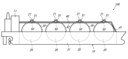
- FIG. 1 is a schematic side view of a floating structure.
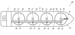
- FIG. 2 is a schematic plan view of the floating structure.
- FIG. 1 is a schematic side view of the floating structure 100
- FIG. 2 is a schematic plan view of the floating structure 100.
- a floating structure 100 according to this embodiment includes a hull 10, a liquefied gas tank 20, a tank cover 30, a flying passage 40, and a relay device 50. These constituent elements will be described in order below.
- a floating structure 100 is a liquefied gas carrier that carries liquefied gas, and includes a navigable hull 10 .
- the concept of direction in the following description corresponds to the concept of direction when a passenger on the floating structure 100 navigates (to the right of the paper surface in FIGS. 1 and 2). Further, hereinafter, the longitudinal direction of the hull 10 is referred to as the "longitudinal direction," the front end portion as the “bow portion,” and the rear end portion as the "stern portion.”
- a control device for controlling the floating structure 100 is installed in the accommodation space 11 .
- the control device receives measurement signals from measuring devices installed at various locations on the hull 10 and transmits control signals to operating devices installed at various locations on the hull 10 .
- a power supply facility is installed in the residential area 11 .
- the power supply equipment supplies power to equipment (including the measuring equipment and operating equipment described above) installed at various locations on the hull 10 .
- the accommodation space 11 is positioned at the stern of the hull 10, but the position of the accommodation space 11 is not limited to this.
- the floating structure 100 is a liquefied gas carrier.
- the floating structure 100 is not limited to a liquefied gas carrier, but may (FSO) or the like.
- the liquefied gas tank 20 is a tank that stores liquefied gas obtained by liquefying combustible gas.
- liquefied hydrogen, liquefied natural gas (LNG), liquefied petroleum gas (LPG), etc. correspond to the liquefied gas.
- a floating structure 100 according to this embodiment includes four liquefied gas tanks 20 .
- the liquefied gas tanks 20 are spherical or ellipsoidal and are arranged in the longitudinal direction. However, the number, shape, and arrangement of the liquefied gas tanks 20 are not limited to those described above.
- a dome portion 21 protruding upward is formed at the top of the liquefied gas tank 20 .
- a pipe connecting the inside and the outside of the liquefied gas tank 20 penetrates through the dome portion 21 .
- wiring extending from the sensor penetrates the dome portion 21 .
- the dome portion 21 functions as a connection portion with other equipment and devices in the liquefied gas tank 20 . Therefore, electric devices tend to concentrate around the dome portion 21 .
- tanks that store liquefied combustible gas are classified into three types according to their strength.
- the first type is a tank that requires a secondary barrier surrounding the entire tank (complete secondary barrier).
- a "secondary barrier” as used herein is a wall for retaining liquefied gas leaking from a tank when the tank is damaged.
- the second type is a tank that is stronger than the first type but requires a partial secondary barrier (partial secondary barrier).
- the third type is an unnecessary tank that is stronger than the second type and is a secondary barrier.
- the first, second, and third types described above correspond to types A, B, and C defined by the International Maritime Organization (IMO), respectively.
- the liquefied gas tank 20 of this embodiment belongs to the third type among the three types described above. That is, the liquefied gas tank 20 of the present embodiment is a tank having strength that does not require a secondary barrier.
- the tank cover 30 is a member that covers the liquefied gas tank 20 .
- a floating structure 100 includes four tank covers 30 .
- Each tank cover 30 is hemispherical and covers the corresponding liquefied gas tank 20 respectively. Strictly speaking, the tank cover 30 covers the liquefied gas tank 20 except for the dome portion 21 .
- a hold space 31 where the liquefied gas tank 20 is located in the hull 10 is covered with the tank cover 30 and the deck 32 .
- the shape of the tank cover 30 is not limited to the above.
- each area in the floating structure 100 is divided into a dangerous area and a non-hazardous area.
- a hazardous area is an area in which non-explosion-proof electrical equipment cannot be installed
- a non-hazardous area is an area in which non-explosion-proof electrical equipment can be installed.
- the liquefied gas tank 20 of this embodiment has a strength that does not require a secondary barrier. Therefore, the surface of the tank cover 30 can be regarded as a non-hazardous area except for the area around the dome portion 21 .
- the degree of freedom in designing the floating structure 100 can be improved. It should be noted that the term “on the surface of the tank cover 30” includes not only a position in contact with the surface of the tank cover 30 but also a position close to the upper surface of the tank cover 30 .
- the flying passage 40 passes over the surface of the tank cover 30 and is a passage through which people can pass.
- the flying passage 40 of this embodiment extends horizontally forward from the accommodation space 11 and passes over the surfaces of the four tank covers 30 . Further, the tip of the flying passage 40 is connected to a staircase 41 extending toward the bow deck 32 .
- an electric circuit 42 is arranged along the flying passage 40 . That is, the electric path 42 is arranged adjacent to the flying passage 40 so as to extend in the longitudinal direction.
- the electric line 42 there are signal cables for the control device installed in the residential area 11 to receive signals from each device, signal cables for transmitting signals from the control device to each device, A power cable, etc. for supplying power to each device from the power supply equipment installed in the
- the relay device 50 is an electrical device located in the middle of a system that transmits information or energy.
- the relay device 50 of this embodiment is non-explosion proof and is positioned on the surface of the tank cover 30 .
- the relay device 50 is housed in an electric device room 51 located on the electric line 42 .
- the electrical equipment room 51 is located on the electric line 42 adjacent to the flying passage 40 . Therefore, the relay device 50 housed in the electrical device room 51 can be accessed from the flying passage 40 . As a result, the operator can easily perform maintenance on the relay device 50 from the flying passage 40 .
- the relay device 50 does not have to be housed in the electric device room 51 located on the electric line 42 .
- it is desirable that the relay device 50 is arranged within 1 m from the flying passage 40 . By arranging the relay device 50 in this way, it becomes possible to access the relay device 50 from the flying passage 40 .
- access means such as stairs are provided in the flying passage 40 so that the operator can access the relay device 50 and the electrical device room 51. may
- the relay device 50 of this embodiment includes a gas sensor, a branch junction box, a remote I/O unit, and a barrier for intrinsically safe explosion-proof devices.
- the above gas sensor is a sensor that detects combustible gas from gas collected through a conduit.
- the gas around the dome portion 21 is collected through the conduit, and the gas sensor detects whether or not the gas contains combustible gas.
- the surface of the tank cover 30 is a dangerous area and the gas sensor is arranged in the accommodation area 11 , it is necessary to arrange a conduit from around the dome part 21 to the accommodation area 11 .
- the gas sensor since the gas sensor is arranged on the surface of the tank cover 30, it is not necessary to arrange the conduit to the accommodation space 11, and the length of the conduit can be shortened.
- the above branch junction box is a device that includes a power circuit breaker or power switch.
- a branch connection box has a function of supplying electric power obtained from one power cable to each electric device via a plurality of power cables. For example, if the surface of the tank cover 30 is a dangerous area and the branch junction box is arranged in the accommodation area 11, many power cables must be arranged from each device to the accommodation area 11. On the other hand, in this embodiment, since the branch junction box is arranged on the surface of the tank cover 30, the number of power cables from the branch junction box to the accommodation space 11 can be reduced. As a result, the overall length of the power cable can be shortened.
- the above remote I/O unit is a unit that converts signals received from multiple devices such as gas sensors into a single signal and transmits it. For example, if the surface of the tank cover 30 is a dangerous area and the remote I/O unit is located in the living quarters 11 , many signal cables must be routed from each device to the living quarters 11 . In contrast, in this embodiment, since the remote I/O unit is arranged on the surface of the tank cover 30, the number of signal cables from the remote I/O unit to the accommodation space 11 can be reduced. As a result, the overall length of the signal cable can be shortened.
- the above-mentioned barrier for intrinsically safe explosion-proof equipment limits the energy supplied to electrical equipment installed in the hazardous area (in this embodiment, the sensor installed around the dome portion 21) to prevent ignition in the hazardous area. It is a device that suppresses the generation of sparks.
- the surface of the tank cover 30 is a hazardous area and a barrier for intrinsically safe explosion-proof equipment is arranged in the accommodation space 11, the cable connecting the sensor and the barrier for the intrinsically safe explosion-proof equipment is It is necessary to arrange from the periphery of the dome part 21 to the living quarters 11 .
- the barrier for the intrinsically safe explosion-proof device is arranged on the surface of the tank cover 30, so the length of the cable connecting the sensor and the barrier for the intrinsically safe device is shortened. can do. Since the cable connecting the sensor and the barrier for intrinsically safe explosion-proof equipment is more expensive than a general cable, according to the present embodiment, the manufacturing cost of the floating structure 100 can be suppressed.
- the relay device 50 of this embodiment is located at a position corresponding to the top of the tank cover 30 . That is, the relay device 50 is located at the same longitudinal position as the top of the corresponding tank cover 30 . As described above, since electric devices are concentrated around the dome portion 21, by positioning the relay device 50 at a position corresponding to the top of the tank cover 30, the conduit or cable connected to the relay device 50 can be effectively routed. can be shortened to
- the floating structure 100 has been described above.
- the relay device 50 is positioned on the surface of the tank cover 30 in this embodiment, electrical devices other than the relay device 50 may be disposed on the surface of the tank cover 30 .
- a photovoltaic power generation system including a photovoltaic panel, a power conditioner, and a battery may be arranged on the surface of the tank cover 30 .
- the floating structure according to the present embodiment includes a liquefied gas tank that stores liquefied combustible gas and has a strength that does not require a secondary barrier, a tank cover that covers the liquefied gas tank, and a surface of the tank cover. located non-explosion proof electrical equipment;
- the floating structure according to the present embodiment further includes a flying passage that passes over the surface of the tank cover and is passable by people, and the electric device is located at a position accessible from the flying passage.
- the electrical equipment includes a gas sensor that detects combustible gas from gas collected through a conduit, a branch connection box including a power circuit breaker or a power switch, A relay device including at least one of a remote I/O unit that converts a received signal into one signal and transmits the signal, and a barrier for intrinsically safe explosion-proof devices.
- the conduit or cable connected to the relay device can be shortened.
- the relay device is positioned at a position corresponding to the top of the tank cover.
- the electrical equipment may be a photovoltaic power generation system including a photovoltaic panel, a power conditioner, and a battery.
- the surface of the tank cover can be effectively used.
Landscapes
- Chemical & Material Sciences (AREA)
- Engineering & Computer Science (AREA)
- Combustion & Propulsion (AREA)
- Mechanical Engineering (AREA)
- Ocean & Marine Engineering (AREA)
- Filling Or Discharging Of Gas Storage Vessels (AREA)
Abstract
Description
本実施形態に係る浮体構造物100は、液化ガスを運搬する液化ガス運搬船であって、航行可能な船体10を備えている。以下の説明における方向の概念は、浮体構造物100の乗船者が航行する方向(図1及び図2において紙面右方)を見たときの方向の概念と一致する。また、以下では、船体10の前後方向を「長手方向」と、前端部分を「船首部」と、後端部分を「船尾部」とそれぞれ称する。
液化ガスタンク20は、可燃性ガスを液化した液化ガスを貯蔵するタンクである。例えば、液化水素、液化天然ガス(LNG)、液化石油ガス(LPG)などが、上記の液化ガスに相当する。本実施形態に係る浮体構造物100は、4つの液化ガスタンク20を備えている。液化ガスタンク20は球状又は楕円体状であって、長手方向に並んでいる。だだし、液化ガスタンク20の数、形状、配置は、上記のものに限定されない。
タンクカバー30は、液化ガスタンク20を覆う部材である。本実施形態に係る浮体構造物100は4つのタンクカバー30を備えている。各タンクカバー30は半球状であって、対応する液化ガスタンク20をそれぞれ覆っている。厳密には、タンクカバー30は液化ガスタンク20のドーム部21を除く部分を覆っている。なお、船体10のうち液化ガスタンク20が位置するホールドスペース31は、このタンクカバー30と甲板32によって覆われている。また、タンクカバー30の形状は上記のものに限定されない。
フライングパッセージ40は、タンクカバー30の表面上を通過しており、人が通行可能な通路である。本実施形態のフライングパッセージ40は、居住区11から前方に向かって水平に延びており、4つのタンクカバー30の表面上を通っている。また、フライングパッセージ40の先端部分は、船首部の甲板32に向かって延びる階段41に接続されている。
中継機器50は、情報又はエネルギを伝達するシステムの中間に位置する電気機器である。本実施形態の中継機器50は、非防爆仕様であり、タンクカバー30の表面上に位置している。具体的には、中継機器50は、電路42上に位置する電気機器室51に収容されている。
以上、本実施形態に係る浮体構造物100について説明した。本実施形態では、中継機器50がタンクカバー30の表面上に位置している場合について説明したが、中継機器50以外の電気機器がタンクカバー30の表面上に配置してもよい。例えば、太陽光発電パネル、パワーコンディショナ、及び、バッテリを含む太陽光発電システムをタンクカバー30の表面上に配置してもよい。
以上のとおり、本実施形態に係る浮体構造物は、液化した可燃性ガスを貯蔵し二次防壁不要の強度を有する液化ガスタンクと、前記液化ガスタンクを覆うタンクカバーと、前記タンクカバーの表面上に位置する非防爆仕様の電気機器と、を備えている。
11 居住区
20 液化ガスタンク
21 ドーム部
30 タンクカバー
31 ホールドスペース
32 甲板
40 フライングパッセージ
41 階段
42 電路
50 中継機器(電気機器)
51 電気機器室
100 浮体構造物
Claims (5)
- 液化した可燃性ガスを貯蔵し二次防壁不要の強度を有する液化ガスタンクと、
前記液化ガスタンクを覆うタンクカバーと、
前記タンクカバーの表面上に位置する非防爆仕様の電気機器と、を備えている、浮体構造物。 - 前記タンクカバーの表面上を通過し、人が通行可能なフライングパッセージをさらに備え、
前記電気機器は、前記フライングパッセージからアクセス可能な位置に位置している、請求項1に記載の浮体構造物。 - 前記電気機器は、導管を介して収集した気体から可燃性ガスを検出するガスセンサ、電源遮断器又は電源開閉器を含む分岐接続箱、複数の機器から受信した信号を1つの信号に変換して送信するリモートI/Oユニット、及び、本質安全型防爆機器用のバリアのうち少なくとも1つを含む中継機器である、請求項1又は2に記載の浮体構造物。
- 前記中継機器は、前記タンクカバーの頂部に対応する位置に位置している、請求項3に記載の浮体構造物。
- 前記電気機器は、太陽光発電パネル、及び、パワーコンディショナ、及び、バッテリを含む太陽光発電システムである、請求項1又は2に記載の浮体構造物。
Priority Applications (2)
| Application Number | Priority Date | Filing Date | Title |
|---|---|---|---|
| KR1020247018800A KR20240112859A (ko) | 2021-12-13 | 2022-12-05 | 부체 구조물 |
| CN202280078487.8A CN118401434A (zh) | 2021-12-13 | 2022-12-05 | 浮体构造物 |
Applications Claiming Priority (2)
| Application Number | Priority Date | Filing Date | Title |
|---|---|---|---|
| JP2021-201588 | 2021-12-13 | ||
| JP2021201588A JP7825985B2 (ja) | 2021-12-13 | 2021-12-13 | 浮体構造物 |
Publications (1)
| Publication Number | Publication Date |
|---|---|
| WO2023112744A1 true WO2023112744A1 (ja) | 2023-06-22 |
Family
ID=86774314
Family Applications (1)
| Application Number | Title | Priority Date | Filing Date |
|---|---|---|---|
| PCT/JP2022/044723 Ceased WO2023112744A1 (ja) | 2021-12-13 | 2022-12-05 | 浮体構造物 |
Country Status (4)
| Country | Link |
|---|---|
| JP (1) | JP7825985B2 (ja) |
| KR (1) | KR20240112859A (ja) |
| CN (1) | CN118401434A (ja) |
| WO (1) | WO2023112744A1 (ja) |
Citations (3)
| Publication number | Priority date | Publication date | Assignee | Title |
|---|---|---|---|---|
| JP2009161032A (ja) * | 2007-12-28 | 2009-07-23 | Shinyo Industries Co Ltd | 船舶搭載の自然エネルギー及び既存動力利用の混合発電システム。 |
| JP2016120814A (ja) * | 2014-12-25 | 2016-07-07 | 三井造船株式会社 | 液化ガス貯蔵設備を備えた浮体構造物 |
| JP2017194166A (ja) * | 2013-06-21 | 2017-10-26 | 川崎重工業株式会社 | 液化ガス保持タンクおよび液化ガス運搬船 |
Family Cites Families (1)
| Publication number | Priority date | Publication date | Assignee | Title |
|---|---|---|---|---|
| KR102413970B1 (ko) | 2015-04-08 | 2022-06-28 | 삼성디스플레이 주식회사 | 와이어 그리드 편광자 및 이의 제조방법 |
-
2021
- 2021-12-13 JP JP2021201588A patent/JP7825985B2/ja active Active
-
2022
- 2022-12-05 CN CN202280078487.8A patent/CN118401434A/zh active Pending
- 2022-12-05 WO PCT/JP2022/044723 patent/WO2023112744A1/ja not_active Ceased
- 2022-12-05 KR KR1020247018800A patent/KR20240112859A/ko active Pending
Patent Citations (3)
| Publication number | Priority date | Publication date | Assignee | Title |
|---|---|---|---|---|
| JP2009161032A (ja) * | 2007-12-28 | 2009-07-23 | Shinyo Industries Co Ltd | 船舶搭載の自然エネルギー及び既存動力利用の混合発電システム。 |
| JP2017194166A (ja) * | 2013-06-21 | 2017-10-26 | 川崎重工業株式会社 | 液化ガス保持タンクおよび液化ガス運搬船 |
| JP2016120814A (ja) * | 2014-12-25 | 2016-07-07 | 三井造船株式会社 | 液化ガス貯蔵設備を備えた浮体構造物 |
Also Published As
| Publication number | Publication date |
|---|---|
| JP7825985B2 (ja) | 2026-03-09 |
| KR20240112859A (ko) | 2024-07-19 |
| CN118401434A (zh) | 2024-07-26 |
| JP2023087286A (ja) | 2023-06-23 |
Similar Documents
| Publication | Publication Date | Title |
|---|---|---|
| CN107000814B (zh) | 具备液化气体储存设备的浮体结构物 | |
| WO2023112795A1 (ja) | 浮体構造物 | |
| JP2023087282A (ja) | 浮体構造物 | |
| JP2023087283A (ja) | 浮体構造物 | |
| WO2011046313A2 (ko) | 가스연료용 연료탱크를 가지는 부유식 구조물 | |
| WO2011046314A2 (ko) | 가스연료용 연료탱크를 가지는 부유식 구조물 | |
| JP2015229430A (ja) | Lng船 | |
| KR102012658B1 (ko) | 선박의 amp 테스트 시스템 | |
| KR20210120189A (ko) | 컨테이너 선박 | |
| JP2023160949A (ja) | 船舶 | |
| JP7825985B2 (ja) | 浮体構造物 | |
| CN111903028A (zh) | 冗余供电系统 | |
| WO2017150250A1 (ja) | 生産設備を備える浮体構造物 | |
| KR20210108717A (ko) | 벤트 마스트 | |
| JP2019108082A (ja) | 洋上浮体式設備、洋上浮体式設備の建造方法、洋上浮体式設備の設計方法、及び洋上浮体式設備への改造方法 | |
| CN114379707A (zh) | 一种低闪点燃料船舶 | |
| Vogler et al. | Fuel cell in maritime applications challenges, chances and experiences | |
| JP7813129B2 (ja) | 浮体構造物 | |
| KR20150038821A (ko) | 트윈 아일랜드 구조를 갖는 대형 컨테이너선의 배전시스템 | |
| KR20170042916A (ko) | 트랜스버스 케이블 랙 및 트레이 설치용 트랜스버스 케이블 트렁크 구조 및 그 트랜스버스 케이블 트렁크 구조를 구비하는 해양구조물 | |
| WO2023112796A1 (ja) | 浮体構造物 | |
| KR101788754B1 (ko) | 부유 저장식 가스 발전플랜트의 배치구조 | |
| JP7834462B2 (ja) | 液化ガス運搬船 | |
| KR102379083B1 (ko) | 선박용 화물탱크 감시시스템 | |
| KR102426977B1 (ko) | 하이브리드 선박 |
Legal Events
| Date | Code | Title | Description |
|---|---|---|---|
| 121 | Ep: the epo has been informed by wipo that ep was designated in this application |
Ref document number: 22907272 Country of ref document: EP Kind code of ref document: A1 |
|
| WWE | Wipo information: entry into national phase |
Ref document number: 202280078487.8 Country of ref document: CN |
|
| ENP | Entry into the national phase |
Ref document number: 20247018800 Country of ref document: KR Kind code of ref document: A |
|
| WWE | Wipo information: entry into national phase |
Ref document number: 1020247018800 Country of ref document: KR |
|
| NENP | Non-entry into the national phase |
Ref country code: DE |
|
| 122 | Ep: pct application non-entry in european phase |
Ref document number: 22907272 Country of ref document: EP Kind code of ref document: A1 |