WO2023105792A1 - 電力変換装置、モータ駆動装置および冷凍サイクル適用機器 - Google Patents
電力変換装置、モータ駆動装置および冷凍サイクル適用機器 Download PDFInfo
- Publication number
- WO2023105792A1 WO2023105792A1 PCT/JP2021/045666 JP2021045666W WO2023105792A1 WO 2023105792 A1 WO2023105792 A1 WO 2023105792A1 JP 2021045666 W JP2021045666 W JP 2021045666W WO 2023105792 A1 WO2023105792 A1 WO 2023105792A1
- Authority
- WO
- WIPO (PCT)
- Prior art keywords
- power
- converter
- smoothing
- voltage
- control unit
- Prior art date
- Legal status (The legal status is an assumption and is not a legal conclusion. Google has not performed a legal analysis and makes no representation as to the accuracy of the status listed.)
- Ceased
Links
Images






Classifications
-
- H—ELECTRICITY
- H02—GENERATION; CONVERSION OR DISTRIBUTION OF ELECTRIC POWER
- H02M—APPARATUS FOR CONVERSION BETWEEN AC AND AC, BETWEEN AC AND DC, OR BETWEEN DC AND DC, AND FOR USE WITH MAINS OR SIMILAR POWER SUPPLY SYSTEMS; CONVERSION OF DC OR AC INPUT POWER INTO SURGE OUTPUT POWER; CONTROL OR REGULATION THEREOF
- H02M1/00—Details of apparatus for conversion
- H02M1/0067—Converter structures employing plural converter units, other than for parallel operation of the units on a single load
- H02M1/007—Plural converter units in cascade
-
- H—ELECTRICITY
- H02—GENERATION; CONVERSION OR DISTRIBUTION OF ELECTRIC POWER
- H02M—APPARATUS FOR CONVERSION BETWEEN AC AND AC, BETWEEN AC AND DC, OR BETWEEN DC AND DC, AND FOR USE WITH MAINS OR SIMILAR POWER SUPPLY SYSTEMS; CONVERSION OF DC OR AC INPUT POWER INTO SURGE OUTPUT POWER; CONTROL OR REGULATION THEREOF
- H02M1/00—Details of apparatus for conversion
- H02M1/12—Arrangements for reducing harmonics from AC input or output
-
- H—ELECTRICITY
- H02—GENERATION; CONVERSION OR DISTRIBUTION OF ELECTRIC POWER
- H02M—APPARATUS FOR CONVERSION BETWEEN AC AND AC, BETWEEN AC AND DC, OR BETWEEN DC AND DC, AND FOR USE WITH MAINS OR SIMILAR POWER SUPPLY SYSTEMS; CONVERSION OF DC OR AC INPUT POWER INTO SURGE OUTPUT POWER; CONTROL OR REGULATION THEREOF
- H02M1/00—Details of apparatus for conversion
- H02M1/14—Arrangements for reducing ripples from DC input or output
-
- H—ELECTRICITY
- H02—GENERATION; CONVERSION OR DISTRIBUTION OF ELECTRIC POWER
- H02M—APPARATUS FOR CONVERSION BETWEEN AC AND AC, BETWEEN AC AND DC, OR BETWEEN DC AND DC, AND FOR USE WITH MAINS OR SIMILAR POWER SUPPLY SYSTEMS; CONVERSION OF DC OR AC INPUT POWER INTO SURGE OUTPUT POWER; CONTROL OR REGULATION THEREOF
- H02M1/00—Details of apparatus for conversion
- H02M1/14—Arrangements for reducing ripples from DC input or output
- H02M1/15—Arrangements for reducing ripples from DC input or output using active elements
-
- H—ELECTRICITY
- H02—GENERATION; CONVERSION OR DISTRIBUTION OF ELECTRIC POWER
- H02M—APPARATUS FOR CONVERSION BETWEEN AC AND AC, BETWEEN AC AND DC, OR BETWEEN DC AND DC, AND FOR USE WITH MAINS OR SIMILAR POWER SUPPLY SYSTEMS; CONVERSION OF DC OR AC INPUT POWER INTO SURGE OUTPUT POWER; CONTROL OR REGULATION THEREOF
- H02M3/00—Conversion of DC power input into DC power output
- H02M3/22—Conversion of DC power input into DC power output with intermediate conversion into AC
- H02M3/24—Conversion of DC power input into DC power output with intermediate conversion into AC by static converters
- H02M3/28—Conversion of DC power input into DC power output with intermediate conversion into AC by static converters using discharge tubes with control electrode or semiconductor devices with control electrode to produce the intermediate AC
- H02M3/325—Conversion of DC power input into DC power output with intermediate conversion into AC by static converters using discharge tubes with control electrode or semiconductor devices with control electrode to produce the intermediate AC using devices of a triode or a transistor type requiring continuous application of a control signal
- H02M3/335—Conversion of DC power input into DC power output with intermediate conversion into AC by static converters using discharge tubes with control electrode or semiconductor devices with control electrode to produce the intermediate AC using devices of a triode or a transistor type requiring continuous application of a control signal using semiconductor devices only
- H02M3/33507—Conversion of DC power input into DC power output with intermediate conversion into AC by static converters using discharge tubes with control electrode or semiconductor devices with control electrode to produce the intermediate AC using devices of a triode or a transistor type requiring continuous application of a control signal using semiconductor devices only with automatic control of the output voltage or current, e.g. flyback converters
-
- H—ELECTRICITY
- H02—GENERATION; CONVERSION OR DISTRIBUTION OF ELECTRIC POWER
- H02M—APPARATUS FOR CONVERSION BETWEEN AC AND AC, BETWEEN AC AND DC, OR BETWEEN DC AND DC, AND FOR USE WITH MAINS OR SIMILAR POWER SUPPLY SYSTEMS; CONVERSION OF DC OR AC INPUT POWER INTO SURGE OUTPUT POWER; CONTROL OR REGULATION THEREOF
- H02M3/00—Conversion of DC power input into DC power output
- H02M3/22—Conversion of DC power input into DC power output with intermediate conversion into AC
- H02M3/24—Conversion of DC power input into DC power output with intermediate conversion into AC by static converters
- H02M3/28—Conversion of DC power input into DC power output with intermediate conversion into AC by static converters using discharge tubes with control electrode or semiconductor devices with control electrode to produce the intermediate AC
- H02M3/325—Conversion of DC power input into DC power output with intermediate conversion into AC by static converters using discharge tubes with control electrode or semiconductor devices with control electrode to produce the intermediate AC using devices of a triode or a transistor type requiring continuous application of a control signal
- H02M3/335—Conversion of DC power input into DC power output with intermediate conversion into AC by static converters using discharge tubes with control electrode or semiconductor devices with control electrode to produce the intermediate AC using devices of a triode or a transistor type requiring continuous application of a control signal using semiconductor devices only
- H02M3/33538—Conversion of DC power input into DC power output with intermediate conversion into AC by static converters using discharge tubes with control electrode or semiconductor devices with control electrode to produce the intermediate AC using devices of a triode or a transistor type requiring continuous application of a control signal using semiconductor devices only of the forward type
- H02M3/33546—Conversion of DC power input into DC power output with intermediate conversion into AC by static converters using discharge tubes with control electrode or semiconductor devices with control electrode to produce the intermediate AC using devices of a triode or a transistor type requiring continuous application of a control signal using semiconductor devices only of the forward type with automatic control of the output voltage or current
- H02M3/33553—Conversion of DC power input into DC power output with intermediate conversion into AC by static converters using discharge tubes with control electrode or semiconductor devices with control electrode to produce the intermediate AC using devices of a triode or a transistor type requiring continuous application of a control signal using semiconductor devices only of the forward type with automatic control of the output voltage or current with galvanic isolation between input and output of both the power stage and the feedback loop
-
- H—ELECTRICITY
- H02—GENERATION; CONVERSION OR DISTRIBUTION OF ELECTRIC POWER
- H02M—APPARATUS FOR CONVERSION BETWEEN AC AND AC, BETWEEN AC AND DC, OR BETWEEN DC AND DC, AND FOR USE WITH MAINS OR SIMILAR POWER SUPPLY SYSTEMS; CONVERSION OF DC OR AC INPUT POWER INTO SURGE OUTPUT POWER; CONTROL OR REGULATION THEREOF
- H02M7/00—Conversion of AC power input into DC power output; Conversion of DC power input into AC power output
- H02M7/02—Conversion of AC power input into DC power output without possibility of reversal
- H02M7/04—Conversion of AC power input into DC power output without possibility of reversal by static converters
- H02M7/06—Conversion of AC power input into DC power output without possibility of reversal by static converters using discharge tubes without control electrode or semiconductor devices without control electrode
-
- H—ELECTRICITY
- H02—GENERATION; CONVERSION OR DISTRIBUTION OF ELECTRIC POWER
- H02M—APPARATUS FOR CONVERSION BETWEEN AC AND AC, BETWEEN AC AND DC, OR BETWEEN DC AND DC, AND FOR USE WITH MAINS OR SIMILAR POWER SUPPLY SYSTEMS; CONVERSION OF DC OR AC INPUT POWER INTO SURGE OUTPUT POWER; CONTROL OR REGULATION THEREOF
- H02M7/00—Conversion of AC power input into DC power output; Conversion of DC power input into AC power output
- H02M7/42—Conversion of DC power input into AC power output without possibility of reversal
- H02M7/44—Conversion of DC power input into AC power output without possibility of reversal by static converters
- H02M7/48—Conversion of DC power input into AC power output without possibility of reversal by static converters using discharge tubes with control electrode or semiconductor devices with control electrode
- H02M7/53—Conversion of DC power input into AC power output without possibility of reversal by static converters using discharge tubes with control electrode or semiconductor devices with control electrode using devices of a triode or transistor type requiring continuous application of a control signal
- H02M7/537—Conversion of DC power input into AC power output without possibility of reversal by static converters using discharge tubes with control electrode or semiconductor devices with control electrode using devices of a triode or transistor type requiring continuous application of a control signal using semiconductor devices only, e.g. single switched pulse inverters
-
- H—ELECTRICITY
- H02—GENERATION; CONVERSION OR DISTRIBUTION OF ELECTRIC POWER
- H02M—APPARATUS FOR CONVERSION BETWEEN AC AND AC, BETWEEN AC AND DC, OR BETWEEN DC AND DC, AND FOR USE WITH MAINS OR SIMILAR POWER SUPPLY SYSTEMS; CONVERSION OF DC OR AC INPUT POWER INTO SURGE OUTPUT POWER; CONTROL OR REGULATION THEREOF
- H02M7/00—Conversion of AC power input into DC power output; Conversion of DC power input into AC power output
- H02M7/42—Conversion of DC power input into AC power output without possibility of reversal
- H02M7/44—Conversion of DC power input into AC power output without possibility of reversal by static converters
- H02M7/48—Conversion of DC power input into AC power output without possibility of reversal by static converters using discharge tubes with control electrode or semiconductor devices with control electrode
- H02M7/53—Conversion of DC power input into AC power output without possibility of reversal by static converters using discharge tubes with control electrode or semiconductor devices with control electrode using devices of a triode or transistor type requiring continuous application of a control signal
- H02M7/537—Conversion of DC power input into AC power output without possibility of reversal by static converters using discharge tubes with control electrode or semiconductor devices with control electrode using devices of a triode or transistor type requiring continuous application of a control signal using semiconductor devices only, e.g. single switched pulse inverters
- H02M7/5387—Conversion of DC power input into AC power output without possibility of reversal by static converters using discharge tubes with control electrode or semiconductor devices with control electrode using devices of a triode or transistor type requiring continuous application of a control signal using semiconductor devices only, e.g. single switched pulse inverters in a bridge configuration
- H02M7/53871—Conversion of DC power input into AC power output without possibility of reversal by static converters using discharge tubes with control electrode or semiconductor devices with control electrode using devices of a triode or transistor type requiring continuous application of a control signal using semiconductor devices only, e.g. single switched pulse inverters in a bridge configuration with automatic control of output voltage or current
-
- H—ELECTRICITY
- H02—GENERATION; CONVERSION OR DISTRIBUTION OF ELECTRIC POWER
- H02M—APPARATUS FOR CONVERSION BETWEEN AC AND AC, BETWEEN AC AND DC, OR BETWEEN DC AND DC, AND FOR USE WITH MAINS OR SIMILAR POWER SUPPLY SYSTEMS; CONVERSION OF DC OR AC INPUT POWER INTO SURGE OUTPUT POWER; CONTROL OR REGULATION THEREOF
- H02M7/00—Conversion of AC power input into DC power output; Conversion of DC power input into AC power output
- H02M7/42—Conversion of DC power input into AC power output without possibility of reversal
- H02M7/44—Conversion of DC power input into AC power output without possibility of reversal by static converters
- H02M7/48—Conversion of DC power input into AC power output without possibility of reversal by static converters using discharge tubes with control electrode or semiconductor devices with control electrode
- H02M7/53—Conversion of DC power input into AC power output without possibility of reversal by static converters using discharge tubes with control electrode or semiconductor devices with control electrode using devices of a triode or transistor type requiring continuous application of a control signal
- H02M7/537—Conversion of DC power input into AC power output without possibility of reversal by static converters using discharge tubes with control electrode or semiconductor devices with control electrode using devices of a triode or transistor type requiring continuous application of a control signal using semiconductor devices only, e.g. single switched pulse inverters
- H02M7/539—Conversion of DC power input into AC power output without possibility of reversal by static converters using discharge tubes with control electrode or semiconductor devices with control electrode using devices of a triode or transistor type requiring continuous application of a control signal using semiconductor devices only, e.g. single switched pulse inverters with automatic control of output wave form or frequency
-
- H—ELECTRICITY
- H02—GENERATION; CONVERSION OR DISTRIBUTION OF ELECTRIC POWER
- H02P—CONTROL OR REGULATION OF ELECTRIC MOTORS, ELECTRIC GENERATORS OR DYNAMO-ELECTRIC CONVERTERS; CONTROLLING TRANSFORMERS, REACTORS OR CHOKE COILS
- H02P27/00—Arrangements or methods for the control of AC motors characterised by the kind of supply voltage
- H02P27/04—Arrangements or methods for the control of AC motors characterised by the kind of supply voltage using variable-frequency supply voltage, e.g. inverter or converter supply voltage
-
- F—MECHANICAL ENGINEERING; LIGHTING; HEATING; WEAPONS; BLASTING
- F25—REFRIGERATION OR COOLING; COMBINED HEATING AND REFRIGERATION SYSTEMS; HEAT PUMP SYSTEMS; MANUFACTURE OR STORAGE OF ICE; LIQUEFACTION SOLIDIFICATION OF GASES
- F25B—REFRIGERATION MACHINES, PLANTS OR SYSTEMS; COMBINED HEATING AND REFRIGERATION SYSTEMS; HEAT PUMP SYSTEMS
- F25B2600/00—Control issues
- F25B2600/02—Compressor control
- F25B2600/021—Inverters therefor
-
- H—ELECTRICITY
- H02—GENERATION; CONVERSION OR DISTRIBUTION OF ELECTRIC POWER
- H02P—CONTROL OR REGULATION OF ELECTRIC MOTORS, ELECTRIC GENERATORS OR DYNAMO-ELECTRIC CONVERTERS; CONTROLLING TRANSFORMERS, REACTORS OR CHOKE COILS
- H02P27/00—Arrangements or methods for the control of AC motors characterised by the kind of supply voltage
Definitions
- the present disclosure relates to a power conversion device, a motor drive device, and a refrigeration cycle application device that convert AC power into desired power.
- a power conversion device that converts AC power supplied from an AC power supply into desired AC power and supplies it to a load such as an air conditioner.
- a power converter which is a control device for an air conditioner, rectifies AC power supplied from an AC power supply with a diode stack, which is a rectifier, and smoothes the power with a smoothing capacitor.
- a technology is disclosed in which the AC power is converted into a desired AC power by an inverter composed of switching elements and output to a compressor motor, which is a load.
- the present disclosure has been made in view of the above, and an object thereof is to obtain a power conversion device capable of suppressing an increase in device size while suppressing deterioration of a smoothing capacitor.
- the power conversion device includes a rectification unit that rectifies first AC power supplied from an AC power supply, and a rectification unit that is connected to an output end of the rectification unit.
- a smoothing section an inverter connected to both ends of the smoothing section for converting the first DC power output from the rectifying section and the smoothing section into second AC power and outputting the second AC power to the motor, and flowing from the rectifying section to the smoothing section a first control unit for controlling the operation of the inverter so that the inverter outputs second AC power including pulsation corresponding to the pulsation of the power to the motor; one or more switching elements; A DC-DC converter connected to both ends and switching a switching element to convert the first DC power into a second DC power, and a pulsation of the power flowing from the rectifying section to the smoothing section by adjusting the switching duty ratio of the switching element. and a second control unit that switches the switching element while changing according to.
- the power conversion device has the effect of suppressing deterioration of the smoothing capacitor and suppressing an increase in size of the device.
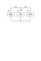
- FIG. 1 is a diagram showing a schematic configuration of a power conversion system realized by applying the power converter according to Embodiment 1;
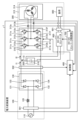
- FIG. 1 is a diagram showing a configuration example of a power converter according to a first embodiment;
- the smoothing unit smoothes the current output from the rectifying unit and shows an example of each current and the smoothing capacitor voltage of the smoothing unit when the current flowing through the inverter is kept constant.
- 4 is a diagram showing an example of each current and the smoothing capacitor voltage of the smoothing unit when the control unit of the power converter according to the first embodiment controls the operation of the inverter to reduce the current flowing through the smoothing unit;
- FIG. 5 is a diagram showing another example of each current and the smoothing capacitor voltage of the smoothing unit of the smoothing unit when the control unit of the power converter according to the first embodiment controls the operation of the inverter to reduce the current flowing through the smoothing unit;
- 1 is a diagram showing a configuration example of a DC-DC converter of a power converter according to a first embodiment
- FIG. 3 is a diagram showing another configuration example of the power conversion device according to the first embodiment
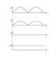
- FIG. 4 is a diagram showing an example of waveforms showing the operation of the DC-DC converter that constitutes the power converter according to the first embodiment
- FIG. 5 is a diagram showing another example of waveforms showing the operation of the DC-DC converter that constitutes the power converter according to the first embodiment;
- FIG. 5 is a diagram showing another example of waveforms showing the operation of the DC-DC converter that constitutes the power converter according to the first embodiment
- FIG. 2 shows a modification of the power conversion device according to the first embodiment
- a power conversion device, a motor drive device, and a refrigeration cycle application device according to embodiments of the present disclosure will be described below in detail based on the drawings.
- FIG. 1 is a diagram showing a schematic configuration of a power conversion system realized by applying a power conversion device according to a first embodiment.
- the power conversion system according to the first embodiment includes a power supply unit 100 configured with a commercial power source, a rectifier circuit, etc., a smoothing unit 200 configured with a smoothing element such as an electrolytic capacitor, a motor, and a load unit 300 configured by an inverter or the like for driving the motor.
- AC power supplied from an AC power supply such as a commercial power supply is rectified by a rectifier circuit.
- the rectified power is output to smoothing section 200 .
- the smoothing unit 200 smoothes DC power, which is rectified power output from the power supply unit 100 .
- the smoothed DC power is output to the load section 300 and consumed by the motor that constitutes the load section 300 .
- the current output from power supply unit 100 to smoothing unit 200 and load unit 300 is I1
- the current input to load unit 300 is I2
- the current flowing out from smoothing unit 200 is I3.
- FIG. 2 is a diagram showing a configuration example of the power converter 1 according to the first embodiment.
- the power converter 1 is connected to an AC power supply 110 such as a commercial power supply, a motor 314 that constitutes a compressor 315 , and a load 800 .
- the power converter 1 converts first AC power supplied from the AC power supply 110 into second AC power, which is three-phase AC power having desired amplitude and phase, and supplies the second AC power to the motor 314 .
- a compressor 315 equipped with a motor 314 is, for example, a hermetic compressor applied to an air conditioner.
- the power conversion device 1 converts the first AC power supplied from the AC power supply 110 into DC power and supplies the DC power to the load 800 .
- the power conversion device 1 includes a voltage/current detection unit 501, a reactor 120, a rectification unit 130, a voltage detection unit 502, a smoothing unit 200, an inverter 310, a control unit 400, a DC-DC converter 600, a voltage A detection unit 601 and a DC-DC converter control unit 700 are provided.
- reactor 120 and rectifying section 130 constitute power supply section 100 of the power conversion system shown in FIG.
- Inverter 310 and compressor 315, DC-DC converter 600 and load 800 constitute load section 300 of the power conversion system shown in FIG.
- the voltage/current detection unit 501 detects the voltage value and current value of the first AC power of the power supply voltage Vs supplied from the AC power supply 110 and outputs the detected voltage value and current value to the control unit 400 .
- Reactor 120 is connected between voltage/current detection unit 501 and rectification unit 130 .
- the rectifying section 130 has a bridge circuit composed of rectifying elements 131 to 134, rectifies the first AC power of the power supply voltage Vs supplied from the AC power supply 110, and outputs the first AC power.
- the rectifier 130 performs full-wave rectification.
- Voltage detection section 502 detects the voltage value of the power rectified by rectification section 130 and outputs the detected voltage value to control section 400 .
- Smoothing section 200 is connected to the output terminal of rectifying section 130 via voltage detecting section 502 .
- Smoothing section 200 has a smoothing capacitor 210 as a smoothing element, and smoothes the power rectified by rectifying section 130 .
- Smoothing capacitor 210 is, for example, an electrolytic capacitor, a film capacitor, or the like. Smoothing capacitor 210 has a capacity to smooth the power rectified by rectifying section 130 .
- the voltage generated in the smoothing capacitor 210 by smoothing does not have a waveform shape of the full-wave rectification of the AC power supply 110, but has a waveform shape in which a voltage ripple corresponding to the frequency of the AC power supply 110 is superimposed on the DC component, and does not pulsate greatly.
- the frequency of this voltage ripple is a two-fold component of the frequency of the power supply voltage Vs when the AC power supply 110 is single-phase, and a six-fold component is a main component when the AC power supply 110 is three-phase. If the power input from AC power supply 110 and the power output from inverter 310 do not change, the amplitude of this voltage ripple is determined by the capacity of smoothing capacitor 210 . For example, it pulsates in such a range that the maximum value of the voltage ripple generated in the smoothing capacitor 210 is less than twice the minimum value.
- the inverter 310 is connected to both ends of the smoothing section 200 , that is, the smoothing capacitor 210 .
- Inverter 310 has switching elements 311a-311f and freewheeling diodes 312a-312f.
- Inverter 310 turns switching elements 311a to 311f on and off under the control of control section 400, and converts the first DC power output from rectifying section 130 and smoothing section 200 to second AC power having a desired amplitude and phase. It is converted into electric power and output to the compressor 315 .
- Current detection units 313 a and 313 b each detect a current value of one phase out of three-phase currents output from inverter 310 and output the detected current value to control unit 400 .
- Control unit 400 acquires two-phase current values among the three-phase current values output from inverter 310, thereby calculating the remaining one-phase current value output from inverter 310.
- Compressor 315 is a load having a motor 314 for driving the compressor. Motor 314 rotates according to the amplitude and phase of the second AC power supplied from inverter 310 to perform compression operation.
- the compressor 315 is a hermetic compressor used in an air conditioner or the like, the load torque of the compressor 315 can often be regarded as a constant torque load.
- reactor 120 may be arranged after rectifying section 130 .
- the voltage/current detector 501, the voltage detector 502, and the current detectors 313a and 313b may be collectively referred to as detectors.
- the voltage value and current value detected by the voltage/current detection unit 501, the voltage value detected by the voltage detection unit 502, and the current values detected by the current detection units 313a and 313b may be referred to as detection values. .
- the control unit 400 is a first control unit included in the power converter 1 .
- the control unit 400 acquires the voltage value and the current value of the first AC power of the power supply voltage Vs from the voltage/current detection unit 501, acquires the voltage value of the power rectified by the rectification unit 130 from the voltage detection unit 502, A current value of the second AC power having a desired amplitude and phase converted by the inverter 310 is obtained from the current detection units 313a and 313b.
- Control unit 400 controls the operation of inverter 310, specifically, the on/off of switching elements 311a to 311f included in inverter 310, using the detection values detected by the respective detection units.
- control unit 400 outputs second AC power including pulsation corresponding to the pulsation of the power flowing from rectifying unit 130 into smoothing capacitor 210 of smoothing unit 200 to compressor 315 as a load. to control the operation of the inverter 310 .
- the pulsation corresponding to the pulsation of the power flowing into the smoothing capacitor 210 of the smoothing section 200 is, for example, the pulsation that varies depending on the frequency of the pulsation of the power flowing into the smoothing capacitor 210 of the smoothing section 200 .
- the control unit 400 suppresses the current flowing through the smoothing capacitor 210 of the smoothing unit 200 .
- the control unit 400 does not have to use all the detection values acquired from each detection unit, and may perform control using some of the detection values.
- the load generated by inverter 310 and compressor 315 can be regarded as a constant load.
- the following description assumes that a current load is connected.
- FIG. FIG. 4 is a diagram showing an example of capacitor voltage Vdc; From the top, the current I1, the current I2, the current I3, and the smoothing capacitor voltage Vdc of the smoothing capacitor 210 generated according to the current I3 are shown.
- the vertical axis of the currents I1, I2 and I3 indicates the current value
- the vertical axis of the smoothing capacitor voltage Vdc indicates the voltage value. All horizontal axes indicate time t.
- the currents I2 and I3 are actually superimposed with the carrier component of the inverter 310, they are omitted here. The same shall apply to the following. As shown in FIG.
- control unit 400 controls current I2 flowing through inverter 310, that is, controls the operation of inverter 310, so as to reduce current I3 flowing through smoothing unit 200.
- FIG. 4 shows the currents I1 to I3 and the smoothing capacitor of the smoothing unit 200 when the control unit 400 of the power converter 1 according to the first embodiment controls the operation of the inverter 310 to reduce the current I3 flowing in the smoothing unit 200.
- 210 is a diagram showing an example of the smoothing capacitor voltage Vdc of 210.
- FIG. From the top the current I1, the current I2, the current I3, and the smoothing capacitor voltage Vdc of the smoothing capacitor 210 generated according to the current I3 are shown.
- the vertical axis of the currents I1, I2 and I3 indicates the current value
- the vertical axis of the smoothing capacitor voltage Vdc indicates the voltage value. All horizontal axes indicate time t.
- the control unit 400 of the power conversion device 1 controls the operation of the inverter 310 so that the current I2 shown in FIG.
- the pulsating component of the current flowing into 200 can be reduced, and the current I3 flowing into smoothing section 200 can be reduced.
- control unit 400 controls the operation of inverter 310 so that current I2 containing a pulsating current whose main component is the frequency component of current I1 flows through inverter 310 .
- the ripple or pulsating component contained in the current I1 is determined by the frequency of the alternating current supplied from the alternating current power supply 110 and the configuration of the rectifying section 130. Therefore, control unit 400 can make the frequency component of the pulsating current superimposed on current I2 a component having a predetermined amplitude and phase. In the example of FIG. 4, a pulsating current having half the amplitude and the same phase as the pulsating component contained in the current I1 is superimposed on the current I2. As the pulsating current superimposed on the current I2 approaches the pulsating component contained in the current I1, the control unit 400 reduces the current I3 flowing through the smoothing unit 200, thereby reducing the pulsating voltage generated in the smoothing capacitor voltage Vdc.
- FIG. 5 shows currents I1 to I3 and smoothing unit 200 when control unit 400 of power converter 1 according to the first embodiment controls the operation of inverter 310 to reduce current I3 flowing through smoothing unit 200.
- 4 is a diagram showing another example of smoothing capacitor voltage Vdc of smoothing capacitor 210.
- Controlling the pulsation of the current flowing through the inverter 310 by controlling the operation of the inverter 310 by the control unit 400 is the same as controlling the pulsation of the second AC power output from the inverter 310 to the compressor 315. is.
- Control unit 400 controls the operation of inverter 310 so that the pulsation of current I3 is smaller than the pulsation of current I3 shown in the example of FIG.
- the alternating current supplied from the alternating current power supply 110 is not particularly limited, and may be single-phase or three-phase.
- Control unit 400 may determine the frequency of the pulsating current superimposed on current I2 according to the first AC power supplied from AC power supply 110 . Specifically, when the first AC power supplied from AC power supply 110 is single-phase, control unit 400 sets the frequency of the pulsating current superimposed on current I2 flowing through inverter 310 to the frequency of the first AC power. is controlled to be twice as large as When the first AC power supplied from AC power supply 110 is three-phase, control unit 400 sets the frequency of the pulsating current to be superimposed on current I2 flowing through inverter 310 to be six times the frequency of the first AC power. Control so that The waveform of the pulsating current to be superimposed on the current I2 is, for example, the shape of the absolute value of a sine wave or the shape of a sine wave.
- Control unit 400 may use the voltage applied to smoothing capacitor 210 or the current flowing through smoothing capacitor 210 to calculate the amount of pulsation, which is the amplitude of the pulsation to be superimposed on the second AC power output from inverter 310.
- the voltage or current of the first AC power supplied from AC power supply 110 may be used to calculate the amount of pulsation included in the second AC power output from inverter 310 .
- a pulsating current having a waveform corresponding to the pulsating component of the current I1 output from the rectifying unit 130 is input to the inverter 310.
- inverter 310 By controlling the operation of inverter 310 so as to be superimposed on current I2, pulsation of current I3 flowing through smoothing section 200 is suppressed.
- the power conversion device 1 connects the DC-DC converter 600 to both ends of the smoothing unit 200, and causes the DC-DC converter 600 to consume the first DC power output by the smoothing unit 200, so that the smoothing unit 200 to reduce the current I3 flowing through.
- a circuit corresponding to the DC-DC converter 600, the voltage detection unit 601, and the DC-DC converter control unit 700 of the power converter 1 is also provided in a general power converter. 1 DC power is consumed by the DC-DC converter 600, the size of the apparatus is not increased.
- inverter 310 The operation of inverter 310 is controlled so that the pulsating current is superimposed on the input current I2 to inverter 310 .
- the pulsating current having a waveform corresponding to the pulsating component of the load torque is a current having a pulsating component that has the same frequency and phase as the pulsating load torque.
- FIG. 6 is a diagram showing a configuration example of the DC-DC converter 600 of the power converter 1 according to the first embodiment.
- the DC-DC converter 600 is an insulated DC-DC converter, and converts the first DC power output from the smoothing section 200 into second DC power of a desired voltage.
- the DC-DC converter 600 is configured to be capable of outputting DC power with a voltage of Vout1 and DC power with a voltage of Vout2 as second DC power.
- the second DC power is output to load 800 .
- the DC-DC converter 600 includes a coil 611, a switching element 612, a freewheeling diode 613, and a surge voltage suppression circuit 614 on the primary side, and coils 621, 622, rectifying elements 623, 624, and capacitors 625, 626 on the secondary side.
- a surge voltage suppressing circuit 614 composed of resistors, capacitors, etc. is connected in parallel to the coil 611 .
- coil 621 and coil 622 are connected in series.
- a capacitor 626 is connected in parallel to the coils 621 and 622 via a rectifying element 624 .
- a rectifying element 624 has an anode connected to the coil 622 and a cathode connected to the capacitor 626 .
- a capacitor 625 is connected in parallel to the coil 621 via a rectifying element 623 .
- the rectifying element 623 has an anode connected to the coil 621 and a cathode connected to the capacitor 625 .
- Coil 621, rectifying element 623, and capacitor 625 constitute a circuit for generating DC power with voltage Vout1
- coil 621, coil 622, rectifying element 624, and capacitor 626 constitute a circuit for generating DC power with voltage Vout2.
- DC-DC converter 600 turns switching element 612 on and off under the control of DC-DC converter control section 700 (not shown), and converts the first DC power output from smoothing section 200 into DC power of voltage Vout1 and The DC power is converted to a voltage Vout2 and output to the load 800 .
- one switching element 612 is provided on the primary side of the DC-DC converter 600, but two or more switching elements may be provided on the primary side.
- the configuration is such that two types of DC power with different voltages are generated and output, it may be configured to generate and output three or more types of DC power with different voltages, or a single DC power may be generated. It may be configured to output.
- one coil, one rectifying element, and one capacitor may be provided.
- the voltage detection section 601 detects the voltage value of the second DC power generated by the DC-DC converter 600 and outputs the detected voltage value to the DC-DC converter control section 700 .
- the DC-DC converter control section 700 is a second control section included in the power converter 1 .
- DC-DC converter control section 700 acquires the voltage value of the second DC power from voltage detection section 601, and controls DC-DC converter 600 based on the acquired voltage value.
- the inverter 310 and the DC-DC converter 600 are individually controlled by different controllers (the controller 400 and the DC-DC converter controller 700).
- controllers the controller 400 and the DC-DC converter controller 700.
- inverter 310 and DC-DC converter 600 have significantly different control speeds of switching elements, that is, switching frequencies, and thus different performances are required of their control units.
- each control unit can be realized with parts having appropriate performance.
- FIG. 7 is a diagram illustrating another configuration example of the power converter according to the first embodiment;
- FIG. A power conversion device 1a shown in FIG. 7 is obtained by replacing the control unit 400 and the DC-DC converter control unit 700 of the power conversion device 1 shown in FIG. 2 with a control unit 400a.
- Control unit 400 a controls inverter 310 and DC-DC converter 600 .
- Control unit 400a controls inverter 310 by control unit 400 described above, and controls DC-DC converter 600 by DC-DC converter control unit 700 described above.
- FIG. 7 is a diagram illustrating another configuration example of the power converter according to the first embodiment;
- FIG. A power conversion device 1a shown in FIG. 7 is obtained by replacing the control unit 400 and the DC-DC converter control unit 700 of the power conversion device 1 shown in FIG. 2 with a control unit 400a.
- Control unit 400 a controls inverter 310 and DC-DC converter 600 .
- Control unit 400a controls inverter 310 by control unit 400 described above, and controls DC-DC converter 600
- the operation of the DC-DC converter control unit 700 of the power conversion device 1 and the control unit 400a of the power conversion device 1a to control the DC-DC converter 600 will be described.
- the control unit 400a of the power converter 1a controls the DC-DC converter 600 will be described.
- the DC-DC converter control section 700 of the power converter 1 can also perform similar control.
- FIG. 8 is a diagram showing an example of waveforms showing the operation of the DC-DC converter 600 that constitutes the power converter 1a according to the first embodiment.
- FIG. 8 shows signal waveforms of each part when the control part 400a switches the switching element 612 of the DC-DC converter 600 with a duty ratio corresponding to the voltage value obtained from the voltage detection part 601.
- the waveforms shown in FIG. 8 indicate, in order from the top, the smoothing capacitor voltage Vdc, the duty ratio Duty of the switching operation of the switching element 612, and the DC power voltage Vout output by the DC-DC converter 600.
- the horizontal axis indicates time t.
- the vertical axes of voltages Vdc and Vout indicate voltage values.
- the control section 400a controls the duty ratio so that the output voltage Vout of the DC-DC converter 600 is constant. Specifically, the control unit 400a switches the switching element 612 while controlling the duty ratio so that the pulsation generated in the smoothing capacitor voltage Vdc becomes maximum at the minimum point and becomes minimum at the maximum point.
- the average duty ratio excluding the pulsating component from the duty ratio, is determined by control from the relationship between the average voltage of Vdc and the average voltage of Vout. determined by The voltage detection unit 601 detects a voltage including a pulsating component generated in Vout, and the control unit 400a controls the DC-DC converter 600 so as to cancel the detected voltage, thereby enabling the operation shown in FIG. Note that FIG.
- FIG. 9 is a diagram showing another example of waveforms showing the operation of the DC-DC converter 600 that constitutes the power converter 1a according to the first embodiment.
- FIG. 9 shows signal waveforms of respective parts when the control unit 400a switches the switching element 612 of the DC-DC converter 600 at a duty ratio corresponding to the voltage values obtained from the voltage/current detection unit 502 and the voltage detection unit 601. there is In the example shown in FIG. 9, the control unit 400a controls the operation of the DC-DC converter 600 so as to output the second DC power on which the same pulsation as that generated in the smoothing capacitor voltage Vdc is superimposed.
- the control unit 400a switches the switching element 612 while controlling the duty ratio so that the pulsation generated in the smoothing capacitor voltage Vdc becomes minimum at the minimum point and becomes maximum at the maximum point.
- the average duty ratio obtained by excluding the pulsating component from the duty ratio is determined in terms of control from the relationship between the average voltage of Vdc and the average voltage of Vout.
- the pulsating component superimposed on the duty ratio is determined in terms of control so as to be similar to the pulsating component of Vdc.
- a pulsating component generated in Vdc is detected by the voltage/current detector 502 and controlled so that this component is superimposed on the duty ratio in the same manner as the inverter 310 shown in FIGS.
- the pulsating component superimposed on the duty ratio can be adjusted by control adjustment, and the amount of the pulsating component generated in Vout can be adjusted accordingly. As a result, the current flowing through smoothing capacitor 210 can be reduced, and smoothing capacitor 210 can be miniaturized.
- FIG. 10 is a diagram showing another example of waveforms showing the operation of the DC-DC converter 600 that constitutes the power converter 1a according to the first embodiment.
- FIG. 10 shows operating waveforms of the DC-DC converter 600 when the switching element 612 is switched at an average duty ratio without superimposing the pulsating component generated in Vdc or Vout on the duty ratio.
- the average duty ratio obtained by excluding the pulsating component from the duty ratio is determined in terms of control from the relationship between the average voltage of Vdc and the average voltage of Vout.
- the DC-DC converter 600 When the DC-DC converter 600 is controlled with an average duty ratio, the DC-DC converter 600 also outputs the pulsating component generated in Vdc to Vout. As a result, the current flowing through smoothing capacitor 210 can be reduced, and smoothing capacitor 210 can be miniaturized.
- the duty ratio according to the voltage value obtained from the voltage/current detection unit 502 and the voltage detection unit 601 is By controlling DC-DC converter 600 with , the capacity of smoothing capacitor 210 or capacitors 625 and 626 can be reduced.
- the control unit 400a When the control unit 400a operates the DC-DC converter 600 to output the second DC power on which the same pulsation as that generated in the smoothing capacitor voltage Vdc is superimposed, the current flowing through the smoothing capacitor 210 can be reduced.
- the amplitude of the output voltage Vout of the DC-DC converter 600 increases. If the amplitude becomes large, the maximum voltage applied to the rectifying elements 623 and 624 on the secondary side of the DC-DC converter 600 will exceed the withstand voltage of the rectifying elements 623 and 624, possibly causing the device to malfunction. .
- the minimum voltage applied to rectifying elements 623 and 624 may exceed the lower limit of the output voltage of DC-DC converter 600, causing load 800 to stop operating. Therefore, the control unit 400a controls the switching element 612 so that the voltages generated by the coils 621 and 622 on the secondary side fall within a predetermined range.
- the upper and lower limits of the voltage generated by the coils 621 and 622 on the secondary side of the DC-DC converter 600 are determined as follows.
- the voltage generated at the coil 611 on the primary side is Vtr1
- the voltages generated at the coils 621 and 622 on the secondary side are Vtr21 and Vtr21, respectively. Let it be Vtr22.
- Vout1_min and Vout2_min be the lower limits of the two-stage voltages Vout1 and Vout2 output by the DC-DC converter 600, respectively.
- the voltage Vout1_min is the lower limit of the voltage at which current flows in the forward direction of the rectifying element 623 or a value higher than this value
- the voltage Vout2_min is the lower limit of the voltage at which current flows in the forward direction of the rectifying element 624 or is higher than this value. set to a higher value.
- the withstand voltage of the rectifying element 623 is Vdi23_max
- the withstand voltage of the rectifying element 624 is Vdi24_max.
- control unit 400a controls the switching element 612 so that Vtr21 and Vtr22 satisfy the following equations (1) and (2).
- control unit 400a controls the voltage (Vtr21) generated in the coil 621 to be equal to or lower than the withstand voltage of the rectifying element 623, and the sum of the voltage generated in the coil 621 and the voltage generated in the coil 622 (Vtr21+Vtr22)
- the switching element 612 is controlled so that the breakdown voltage of the switching element 612 is less than or equal to
- control unit 400a controls the switching element 612 so that Vtr21 and Vtr22 satisfy the following equations (3) and (4).
- control unit 400a controls that the voltage (Vtr21) generated in the coil 621 is greater than the lower limit value of the output voltage Vout1, and the sum of the voltage generated in the coil 621 and the voltage generated in the coil 622 (Vtr21+Vtr22) is The switching element 612 is controlled so as to be higher than the lower limit of the output voltage Vout2.
- the first AC power supplied from the AC power supply 110 is rectified by the rectification unit 130, and the rectified power is smoothed by the smoothing unit 200.
- the inverter 310 converts the first DC power output from the smoothing unit 200 into the second AC power and outputs it to the compressor 315
- the DC-DC converter 600 converts the first DC power into the second AC power. It is converted into DC power and output to the load 800 .
- inverter 310 causes the second AC power to include a pulsating component corresponding to the pulsation of the power flowing into smoothing unit 200 from rectifying unit 130 , thereby reducing current I3 flowing through smoothing unit 200 .
- the smoothing capacitor 210 can be suppressed, and the capacity can be reduced, as compared with the case where the second AC power is not controlled to include a pulsation component corresponding to the pulsation of the power flowing into the smoothing unit 200.
- the smoothing section 200 is configured with a plurality of smoothing capacitors 210, the number of smoothing capacitors 210 configuring the smoothing section 200 can be reduced.
- DC-DC converter 600 changes the duty ratio when switching element 612 according to the pulsation of the power flowing from rectifying section 130 to smoothing section 200 .
- pulsation of output voltages Vout1 and Vout2 of DC-DC converter 600 can be suppressed.
- capacitors with a small capacity can be used as the capacitors 625 and 626, and the size of the device can be reduced.
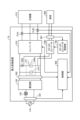
- FIG. 11 is a diagram illustrating a modification of the power converter according to the first embodiment;
- the power conversion device 1b shown in FIG. 11 has a configuration in which the smoothing section 200 of the power conversion device 1 shown in FIG.
- two smoothing capacitors 210 and 211 connected in parallel constitute a smoothing section 200b, and a rectifying element 602 is connected in series to the smoothing capacitor 211.
- FIG. A DC-DC converter 600 is connected in parallel with the smoothing capacitor 211 .
- a rectifying element may also be connected in series with smoothing capacitor 210 .
- the smoothing section 200b may be configured with three or more smoothing capacitors.
- the rectifying element 602 is connected in series to the smoothing capacitor 211 to which the DC-DC converter 600 is connected, the DC-DC converter 600 due to the pulsating component of the voltage output by the rectifying unit 130 can reduce the impact of
- FIG. 11 shows an example in which the smoothing unit 200 of the power converter 1 is replaced with the smoothing unit 200b and the rectifying element 602 is added. can also be added. Further, the rectifying section 130 of the power converters 1 to 1b may include a booster circuit to boost the power obtained by rectifying the first AC power, thereby improving the power factor.
- each control unit control unit 400, 400a
- each power conversion device power conversion device 1, 1a, 1b
- the hardware configuration of each control unit is the same.
- FIG. 12 is a diagram showing an example of a hardware configuration that implements a control unit included in the power converter.
- a control unit of the power converter is realized by, for example, a processor 91 and a memory 92 shown in FIG. 12 .
- the processor 91 is a CPU (Central Processing Unit, also referred to as a central processing unit, processing unit, arithmetic unit, microprocessor, microcomputer, processor, DSP (Digital Signal Processor)).
- the memory 92 is RAM (Random Access Memory), ROM (Read Only Memory), flash memory, EPROM (Erasable Programmable Read Only Memory), EEPROM (registered trademark) (Electrically Erasable Programmable Read Only Memory), or the like.
- the memory 92 stores a program for operating as a control unit of the power converter.
- a control unit of the power converter is implemented by the processor 91 reading and executing a program stored in the memory 92 .
- the above program stored in the memory 92 may be provided to the user or the like while being written on a storage medium such as a CD (Compact Disc)-ROM, a DVD (Digital Versatile Disc)-ROM, etc. Alternatively, it may be provided via a network.
- the control unit can also be realized by a dedicated processing circuit, for example, a single circuit, a composite circuit, an ASIC (Application Specific Integrated Circuit), an FPGA (Field Programmable Gate Array), or a circuit that combines these. .
- a dedicated processing circuit for example, a single circuit, a composite circuit, an ASIC (Application Specific Integrated Circuit), an FPGA (Field Programmable Gate Array), or a circuit that combines these. .
- the DC-DC converter control section 700 of the power conversion device 1 can also be realized with similar hardware.
- Embodiment 2 a device that can be realized by applying each power conversion device described in Embodiment 1 will be described.
- a refrigerating cycle-applied equipment using the power converter 1 described in the first embodiment will be described.
- FIG. 13 is a diagram showing a configuration example of a refrigeration cycle application device 900 according to the second embodiment.
- a refrigerating cycle applied equipment 900 according to the second embodiment includes a motor drive device 10 to which the power conversion device 1 described in the first embodiment is applied.
- the refrigerating cycle applied equipment 900 has a refrigerating cycle configuration in which a four-way valve 902, a compressor 903, a heat exchanger 906, an expansion valve 908, and a heat exchanger 910 are attached via a refrigerant pipe 912. It has The compressor 903 corresponds to the compressor 315 shown in FIG. 2 and the like.
- the compressor 903 is provided with a compression mechanism 904 that compresses the refrigerant circulating in the refrigerant pipe 912 and a motor 905 that operates the compression mechanism 904 .
- the refrigeration cycle application device 900 having such a configuration can be used, for example, in air conditioners, heat pump water heaters, refrigerators, refrigerators, and the like.
- 1, 1a, 1b power conversion device, 10 motor drive device 100 power supply section, 110 AC power supply, 120 reactor, 130 rectification section, 131 to 134, 602, 623, 624 rectification element, 200, 200b smoothing section, 210, 211 smoothing capacitor, 300 load section, 310 inverter, 311a to 311f, 612 switching element, 312a to 312f, 613 freewheeling diode, 313a, 313b current detection section, 314, 905 motor, 315, 903 compressor, 400, 400a control section, 501 Voltage current detection unit, 502, 601 Voltage detection unit, 600 DC-DC converter, 611, 621, 622 Coil, 614 Surge voltage suppression circuit, 625, 626 Capacitor, 700 DC-DC converter control unit, 800 Load, 900 Refrigerant Cycle application equipment, 902 four-way valve, 904 compression mechanism, 906, 910 heat exchanger, 908 expansion valve, 912 refrigerant piping.
Landscapes
- Engineering & Computer Science (AREA)
- Power Engineering (AREA)
- Inverter Devices (AREA)
- Dc-Dc Converters (AREA)
Priority Applications (4)
| Application Number | Priority Date | Filing Date | Title |
|---|---|---|---|
| JP2023566063A JPWO2023105792A1 (https=) | 2021-12-10 | 2021-12-10 | |
| CN202180104727.2A CN118451644A (zh) | 2021-12-10 | 2021-12-10 | 电力转换装置、马达驱动装置以及制冷循环应用设备 |
| PCT/JP2021/045666 WO2023105792A1 (ja) | 2021-12-10 | 2021-12-10 | 電力変換装置、モータ駆動装置および冷凍サイクル適用機器 |
| US18/703,855 US20250226738A1 (en) | 2021-12-10 | 2021-12-10 | Power converter, motor driver, and refrigeration-cycle applied equipment |
Applications Claiming Priority (1)
| Application Number | Priority Date | Filing Date | Title |
|---|---|---|---|
| PCT/JP2021/045666 WO2023105792A1 (ja) | 2021-12-10 | 2021-12-10 | 電力変換装置、モータ駆動装置および冷凍サイクル適用機器 |
Publications (1)
| Publication Number | Publication Date |
|---|---|
| WO2023105792A1 true WO2023105792A1 (ja) | 2023-06-15 |
Family
ID=86729976
Family Applications (1)
| Application Number | Title | Priority Date | Filing Date |
|---|---|---|---|
| PCT/JP2021/045666 Ceased WO2023105792A1 (ja) | 2021-12-10 | 2021-12-10 | 電力変換装置、モータ駆動装置および冷凍サイクル適用機器 |
Country Status (4)
| Country | Link |
|---|---|
| US (1) | US20250226738A1 (https=) |
| JP (1) | JPWO2023105792A1 (https=) |
| CN (1) | CN118451644A (https=) |
| WO (1) | WO2023105792A1 (https=) |
Families Citing this family (1)
| Publication number | Priority date | Publication date | Assignee | Title |
|---|---|---|---|---|
| JP7345673B2 (ja) | 2020-10-26 | 2023-09-15 | 三菱電機株式会社 | 電力変換装置、モータ駆動装置および冷凍サイクル適用機器 |
Citations (3)
| Publication number | Priority date | Publication date | Assignee | Title |
|---|---|---|---|---|
| JP2007080771A (ja) * | 2005-09-16 | 2007-03-29 | Nec Lighting Ltd | 照明用低圧電源回路、照明装置および照明用低圧電源出力方法 |
| JP2016073203A (ja) * | 2014-09-30 | 2016-05-09 | ダイキン工業株式会社 | 電力変換装置 |
| JP2020096424A (ja) * | 2018-12-11 | 2020-06-18 | 東芝キヤリア株式会社 | 冷凍サイクル装置 |
-
2021
- 2021-12-10 CN CN202180104727.2A patent/CN118451644A/zh active Pending
- 2021-12-10 WO PCT/JP2021/045666 patent/WO2023105792A1/ja not_active Ceased
- 2021-12-10 JP JP2023566063A patent/JPWO2023105792A1/ja not_active Withdrawn
- 2021-12-10 US US18/703,855 patent/US20250226738A1/en active Pending
Patent Citations (3)
| Publication number | Priority date | Publication date | Assignee | Title |
|---|---|---|---|---|
| JP2007080771A (ja) * | 2005-09-16 | 2007-03-29 | Nec Lighting Ltd | 照明用低圧電源回路、照明装置および照明用低圧電源出力方法 |
| JP2016073203A (ja) * | 2014-09-30 | 2016-05-09 | ダイキン工業株式会社 | 電力変換装置 |
| JP2020096424A (ja) * | 2018-12-11 | 2020-06-18 | 東芝キヤリア株式会社 | 冷凍サイクル装置 |
Also Published As
| Publication number | Publication date |
|---|---|
| CN118451644A (zh) | 2024-08-06 |
| US20250226738A1 (en) | 2025-07-10 |
| JPWO2023105792A1 (https=) | 2023-06-15 |
Similar Documents
| Publication | Publication Date | Title |
|---|---|---|
| JP4509936B2 (ja) | 三相電力変換装置および電力変換装置 | |
| JP5997677B2 (ja) | 電力変換装置及び空気調和装置 | |
| JP3422218B2 (ja) | コンバータ | |
| JP7345674B2 (ja) | 電力変換装置、モータ駆動装置および冷凍サイクル適用機器 | |
| JP7471442B2 (ja) | 電力変換装置、モータ駆動装置および冷凍サイクル適用機器 | |
| CN116420302B (zh) | 电力转换装置、马达驱动装置以及制冷循环应用设备 | |
| WO2022172419A1 (ja) | 電力変換装置、モータ駆動装置および空気調和機 | |
| US20240039427A1 (en) | Power converting apparatus, motor drive apparatus, and refrigeration cycle application device | |
| WO2023105792A1 (ja) | 電力変換装置、モータ駆動装置および冷凍サイクル適用機器 | |
| WO2022172418A1 (ja) | 電力変換装置、モータ駆動装置および冷凍サイクル適用機器 | |
| WO2023084604A1 (ja) | 電力変換装置、モータ駆動装置および冷凍サイクル適用機器 | |
| KR101624048B1 (ko) | 전력 변환 장치 및 공기 조화기 | |
| WO2019163068A1 (ja) | 整流回路装置 | |
| JP7152578B2 (ja) | 直流電源装置および空気調和機 | |
| WO2023084726A1 (ja) | 電力変換装置及び冷凍サイクル適用機器 | |
| WO2023238229A1 (ja) | 電力変換装置、モータ駆動装置及び冷凍サイクル適用機器 | |
| WO2023131990A1 (ja) | 電力変換装置、モータ駆動装置および冷凍サイクル適用機器 | |
| JP2010172152A (ja) | 電力変換装置 | |
| JP2019122121A (ja) | インバータ装置、昇圧回路制御方法及びプログラム |
Legal Events
| Date | Code | Title | Description |
|---|---|---|---|
| 121 | Ep: the epo has been informed by wipo that ep was designated in this application |
Ref document number: 21967284 Country of ref document: EP Kind code of ref document: A1 |
|
| WWE | Wipo information: entry into national phase |
Ref document number: 2023566063 Country of ref document: JP |
|
| WWE | Wipo information: entry into national phase |
Ref document number: 18703855 Country of ref document: US |
|
| WWE | Wipo information: entry into national phase |
Ref document number: 202180104727.2 Country of ref document: CN |
|
| NENP | Non-entry into the national phase |
Ref country code: DE |
|
| 122 | Ep: pct application non-entry in european phase |
Ref document number: 21967284 Country of ref document: EP Kind code of ref document: A1 |
|
| WWP | Wipo information: published in national office |
Ref document number: 18703855 Country of ref document: US |