WO2023105625A1 - 光伝送システム、および光伝送システムの制御方法 - Google Patents
光伝送システム、および光伝送システムの制御方法 Download PDFInfo
- Publication number
- WO2023105625A1 WO2023105625A1 PCT/JP2021/044904 JP2021044904W WO2023105625A1 WO 2023105625 A1 WO2023105625 A1 WO 2023105625A1 JP 2021044904 W JP2021044904 W JP 2021044904W WO 2023105625 A1 WO2023105625 A1 WO 2023105625A1
- Authority
- WO
- WIPO (PCT)
- Prior art keywords
- wavelength
- subband
- transmission system
- optical transmission
- optical
- Prior art date
- Legal status (The legal status is an assumption and is not a legal conclusion. Google has not performed a legal analysis and makes no representation as to the accuracy of the status listed.)
- Ceased
Links
Images







Classifications
-
- H—ELECTRICITY
- H04—ELECTRIC COMMUNICATION TECHNIQUE
- H04J—MULTIPLEX COMMUNICATION
- H04J14/00—Optical multiplex systems
- H04J14/02—Wavelength-division multiplex systems
-
- H—ELECTRICITY
- H04—ELECTRIC COMMUNICATION TECHNIQUE
- H04B—TRANSMISSION
- H04B10/00—Transmission systems employing electromagnetic waves other than radio-waves, e.g. infrared, visible or ultraviolet light, or employing corpuscular radiation, e.g. quantum communication
- H04B10/07—Arrangements for monitoring or testing transmission systems; Arrangements for fault measurement of transmission systems
- H04B10/075—Arrangements for monitoring or testing transmission systems; Arrangements for fault measurement of transmission systems using an in-service signal
- H04B10/079—Arrangements for monitoring or testing transmission systems; Arrangements for fault measurement of transmission systems using an in-service signal using measurements of the data signal
- H04B10/0795—Performance monitoring; Measurement of transmission parameters
- H04B10/07955—Monitoring or measuring power
-
- H—ELECTRICITY
- H04—ELECTRIC COMMUNICATION TECHNIQUE
- H04B—TRANSMISSION
- H04B10/00—Transmission systems employing electromagnetic waves other than radio-waves, e.g. infrared, visible or ultraviolet light, or employing corpuscular radiation, e.g. quantum communication
- H04B10/29—Repeaters
- H04B10/291—Repeaters in which processing or amplification is carried out without conversion of the main signal from optical form
- H04B10/293—Signal power control
-
- H—ELECTRICITY
- H04—ELECTRIC COMMUNICATION TECHNIQUE
- H04J—MULTIPLEX COMMUNICATION
- H04J14/00—Optical multiplex systems
- H04J14/02—Wavelength-division multiplex systems
- H04J14/0221—Power control, e.g. to keep the total optical power constant
-
- H—ELECTRICITY
- H04—ELECTRIC COMMUNICATION TECHNIQUE
- H04J—MULTIPLEX COMMUNICATION
- H04J14/00—Optical multiplex systems
- H04J14/02—Wavelength-division multiplex systems
- H04J14/0221—Power control, e.g. to keep the total optical power constant
- H04J14/02216—Power control, e.g. to keep the total optical power constant by gain equalization
Definitions
- the present invention relates to an optical transmission system and the like, and more particularly to an optical transmission system and the like using an optical fiber as a transmission line.
- optical transmission system using an optical fiber as a transmission line is known.
- wavelength bands such as C-band (Conventional Band) and L-band (Long Wave Band) are used as optical communication wavelength bands.
- the C-band wavelength band is 1530 nm to 1565 nm
- the L-band wavelength band is 1565 nm to 1625 nm.
- the optical fiber has a high light transmittance. In other words, the transmission loss of the optical fiber is low in the C-band wavelength band. Therefore, the C-band wavelength band is suitable for long-distance transmission.
- Such an optical transmission system includes, for example, a pair of terminal stations for transmission and reception, an optical fiber as a transmission line connecting the pair of terminal stations, and a plurality of repeaters for relaying the optical fibers. be done.
- Each of the plurality of repeaters includes an optical amplification section that amplifies signal light that attenuates while propagating through a long-distance optical fiber.
- An impurity-doped optical fiber amplifier that amplifies the signal light itself is used as the optical amplifier.
- This impurity-doped optical fiber amplifier includes an EDFA (Erbium-Doped Optical Fiber Amplifier) in which an optical fiber is doped with erbium (Er) ions, which are an example of rare earth ions, as impurities.
- EDFA Erbium-Doped Optical Fiber Amplifier
- Impurity-doped optical fiber amplifiers generally have a large gain for signal light with a long wavelength and a small gain for signal light with a short wavelength in the wavelength band of the signal light to be amplified, as a tendency of amplification characteristics.
- a repeater inserted into an optical fiber is designed so that the output level of signal light with a short wavelength in the wavelength band of signal light to be input and amplified exceeds a predetermined level.
- the gain of the fiber amplifier is adjusted.
- an equalizer connected to the next stage of the impurity-doped optical fiber amplifier cuts off the portion exceeding the predetermined level. , equalization processing is performed to equalize the output levels.
- the portion cut by the equalization processing of this equalizer does not contribute to the optical transmission through the optical fiber, resulting in energy loss.
- An optical transmission system capable of reducing this energy loss is desired.
- Patent Document 1 relates to a method for amplifying wavelength division multiplexing (WDM) signal light.
- WDM wavelength division multiplexing
- wavelength multiplexed signal light is split into signal lights of a plurality of wavelength bands by a demultiplexer.
- An amplification method has been proposed in which signal lights of respective wavelength bands are multiplexed by a multiplexer.
- part of the signal light in each wavelength band amplified by the optical amplifier is split, the power of the split light is measured, and the gain of the optical amplifier is calculated based on the measurement result. are individually adjusted so that the wavelength-to-wavelength deviation of the optical output level generated in each optical amplifier is within a preset range.
- wavelength multiplexed signal light is split into signal lights of a plurality of wavelength bands by a demultiplexing device, and the split signal lights of each wavelength band are sent to respective optical amplifiers.
- the energy loss due to the equalization processing of the equalizer when applying a configuration in which the amplified signal light of each wavelength band is multiplexed by a multiplexing device after amplification (FIG. 13B).
- the wavelength of signal light in the wavelength band amplified by each optical amplifier is Band width narrows.
- the difference between the gain of the signal light having a long wavelength and the gain of the signal light having a short wavelength becomes small.
- the gain of the optical amplifier is adjusted so that the output level of the signal light with the short wavelength out of the wavelength band of the signal light input and amplified by each optical amplifier exceeds the predetermined level, the above predetermined level cannot be achieved. becomes smaller.
- wavelength-multiplexed signal light is split into signal lights of a plurality of wavelength bands by a demultiplexing device, and the split signal lights of each wavelength band are amplified by corresponding optical amplifiers.
- a new problem of a configuration in which, after amplification, the amplified signal light of each wavelength band is multiplexed by a multiplexing device will be examined.
- the energy loss caused by the gain variation that occurs in the optical amplification of wideband wavelength multiplexed signal light can be reduced by splitting the wavelength multiplexed signal light into signal lights of a plurality of wavelength bands with a demultiplexing device, as proposed in Patent Document 1.
- a demultiplexing device as proposed in Patent Document 1.
- the permissible range for standard deviation fluctuations in output intensity due to deterioration over time is about 0.03 dB per amplifier, so the gap must be kept within 0.03 dB. Therefore, filling the output intensity gap caused by aged deterioration is a challenge.
- An object of the present invention is to provide an optical transmission system with a wide band and small gain variation, and a control method thereof, in view of the above-mentioned problems.
- an optical transmission system provides a pair of terminal stations for mutually transmitting and receiving wavelength division multiplexed (WDM) signal light, and propagating the wavelength division multiplexed signal light transmitted and received by the pair of terminal stations.
- WDM wavelength division multiplexed
- An optical transmission system comprising an optical fiber and at least one repeater inserted into the optical fiber;
- the repeater divides the wavelength multiplexed signal light into a plurality of subbands containing signal light of a plurality of wavelength bands, and after amplifying the divided plurality of subbands by a plurality of corresponding optical amplifiers, an optical amplifier for combining the amplified subbands;
- the divided plurality of sub-bands includes a first sub-band on the relatively short wavelength side and a second sub-band on the relatively long wavelength side, Received by the terminal station on the receiving side of the pair of terminal stations, a monitor unit for monitoring the output power of the channel with the longest wavelength in the first subband and the output power of the channel with the shortest wavelength in the second subband;
- the wavelength multiplexed signal light so that the gap between the output power of the channel with the longest wavelength in the first subband and the output power of the channel with the shortest wavelength in the second subband is reduced. and a control unit that transmits a control signal
- a control method for an optical transmission system includes a pair of terminal stations that mutually transmit and receive wavelength division multiplexed (WDM) signal light, an optical fiber that propagates the wavelength division multiplexed signal light transmitted and received by the pair of terminal stations, and a method of controlling an optical transmission system comprising at least one repeater inserted;
- the repeater divides the wavelength multiplexed signal light into a plurality of subbands containing signal light of a plurality of wavelength bands, and after amplifying the divided plurality of subbands by a plurality of corresponding optical amplifiers, combining the amplified sub-bands,
- the divided plurality of sub-bands includes a first sub-band on the relatively short wavelength side and a second sub-band on the relatively long wavelength side, Received by the terminal station on the receiving side of the pair of terminal stations, monitoring the output power of the channel with the longest wavelength in the first subband and the output power of the channel with the shortest wavelength in the second subband;
- the wavelength multiplexed signal light so that the
- the present invention can provide an optical transmission system with a wide band and small gain variation, and a control method thereof.
- FIG. 1 is a block diagram illustrating an optical transmission system according to an embodiment of the generic concept of the present invention
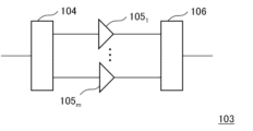
- FIG. 1B is a block diagram for explaining the configuration of the repeater in FIG. 1A
- FIG. 1 is a block diagram illustrating an optical transmission system according to a first embodiment of the invention
- FIG. 2B is a block diagram for explaining the configuration and amplification characteristics of the repeater of FIG. 2A
- FIG. 4 is a graph for explaining the basic principle of amplification characteristics of an optical amplifier
- 2B is a block diagram for explaining a more specific configuration of the optical transmission system of FIG. 2A
- FIG. 3 is a graph for explaining amplification characteristics of an optical amplifier included in FIG. 2B
- FIG. 10 is a graph for explaining the control method of the optical transmission system according to the second embodiment of the present invention
- FIG. 9 is a graph for explaining a modified example of the control method for the optical transmission system according to the second embodiment of the present invention
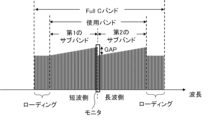
- 4 is a graph for explaining effects of the embodiment of the present invention
- FIG. 10 is a graph for explaining the control method of the optical transmission system according to the second embodiment of the present invention
- FIG. 10 is a graph for explaining the control method of the optical transmission system according to the second embodiment of the present invention
- FIG. FIG. 10 is a graph for explaining the control method of the optical transmission system according to the second embodiment of the present invention
- FIG. FIG. 11 is a graph for explaining a control method for an optical transmission system according to a third embodiment of the present invention
- FIG. 10 is a graph for explaining a control method for an optical transmission system according to a fourth embodiment of the present invention
- FIG. FIG. 11 is a graph for explaining a control method for an optical transmission system according to a fifth embodiment of the present invention
- FIG. FIG. 11 is a graph for explaining amplification characteristics of an optical amplifier in an optical transmission system according to a fifth embodiment of the present invention
- FIG. FIG. 11 is a graph for explaining amplification characteristics of an optical amplifier in an optical transmission system according to a fifth embodiment of the present invention
- FIG. FIG. 11 is a graph for explaining a control method for an optical transmission system according to a sixth embodiment of the present invention
- FIG. 2 is a conceptual diagram for explaining amplification characteristics of an optical amplifier of the background art and energy loss due to equalization processing
- FIG. 2 is a conceptual diagram for explaining amplification characteristics of an optical amplifier of the background art and energy loss due to equalization processing, assuming a case where the configuration proposed by Patent Document 1 is applied
- 13B is a graph for explaining amplification characteristics when it is assumed that the optical amplifier of FIG. 13B has changed with time;
- FIG. 1A is a block diagram illustrating an optical transmission system according to a generic embodiment of the present invention.
- FIG. 1B is a block diagram for explaining the configuration of the repeater of FIG. 1A.
- the optical transmission system of FIG. 1A is, for example, a system that includes terminal stations on land and optical fibers that connect the terminal stations and propagate wavelength multiplexed signal light.
- a submarine cable system using a submarine cable as the optical fiber is assumed.
- the optical transmission system of FIG. 1A includes terminal stations 102A and 102B as an example of a pair of terminal stations that mutually transmit and receive wavelength division multiplexed (WDM) signal light, and the terminal stations 102A and 102B transmit and receive wavelength multiplexed signal light. and at least one repeater 103 inserted into the optical fiber 101 .
- the repeater 103 in FIG. 1A includes a demultiplexer 104, a plurality of optical amplifiers 105 1 to 105 m (where m is an integer of 2 or more), a multiplexer 106, including.
- the demultiplexer 104 divides the wavelength multiplexed signal light input to the repeater 103 into a plurality of subbands containing signal lights of a plurality of wavelength bands.
- a plurality of optical amplifiers 105 1 to 105 m each amplify the wavelength multiplexed signal light divided into a plurality of subbands.
- the plurality of optical amplifiers 105 1 to 105 m are optical amplifiers typified by EDFAs (erbium-doped optical fiber amplifiers), which amplify and output optical signals using pumping light.
- the multiplexer 106 multiplexes and outputs the wavelength multiplexed signal lights amplified by the optical amplifiers 105 1 to 105 m .
- the plurality of subbands includes at least a first subband on the relatively short wavelength side and a second subband on the relatively long wavelength side.
- a monitor section 108 monitors the output power of the channel with the shortest wavelength among the channels.
- the optical transmission system of FIG. 1A further has a small gap between the output power of the channel with the longest wavelength in the first subband and the output power of the channel with the shortest wavelength in the second subband.
- a control unit 109 for transmitting a control signal to a terminal station on the transmission side that transmits the wavelength multiplexed signal light.
- the monitor unit 108 monitors the output power of the channel with the longest wavelength among the first subbands on the relatively short wavelength side, and monitors the output power of the second channel on the relatively long wavelength side. The output power of the channel with the shortest wavelength among the subbands is monitored.
- control unit 109 controls the output power of the channel with the longest wavelength in the first subband and the output power of the channel with the shortest wavelength in the second subband so that the gap between the output power and the channel with the shortest wavelength becomes smaller.
- a control signal that reduces this gap is transmitted to the terminal station on the transmission side that transmits the wavelength multiplexed signal light.
- the terminal station on the transmitting side changes the state regarding transmission of wavelength division multiplexing (WDM) signal light.
- WDM wavelength division multiplexing
- the optical transmission system of FIG. 1A even if the optical amplifier or the like included in the repeater 103 changes over time after the start of operation, the output power of the channel with the longest wavelength in the first subband and the above By controlling to reduce the gap between the output power of the channel with the shortest wavelength in the second subband, variations in the amplification characteristics of the optical amplifier included in the repeater 103 are reduced, and the energy utilization efficiency is improved.
- the optical transmission system can be realized and the performance of the optical transmission system can be maintained. A more specific optical transmission system and its control method will be described below.
- FIG. 2A is a block diagram illustrating an optical transmission system according to the first embodiment of the invention.
- FIG. 2B is a block diagram for explaining the configuration and amplification characteristics of the repeater in FIG. 2A.
- FIG. 2C is a graph for explaining the basic principle of amplification characteristics of an optical amplifier.
- FIG. 4 is a graph for explaining amplification characteristics of the optical amplifier included in FIG. 2B.
- the optical transmission system of FIG. 2A includes a terminal station 12A (transmitting-side terminal station Tx) that transmits wavelength-multiplexed (WDM) signal light, and a terminal station 12B (transmitting-side terminal station Rx) that receives the wavelength-multiplexed signal light. , and an optical fiber 11 that propagates wavelength multiplexed signal light transmitted and received by the terminal stations 12A and 12B. Furthermore, the optical transmission system of FIG. 2A includes at least one repeater 13 inserted into this optical fiber 11 . Note that FIG. 2A shows an example in which seven repeaters 13 are inserted into the optical fiber 11 .
- the repeater 13 of FIG. 2A includes a demultiplexer 14, a plurality of optical amplifiers 15 1 to 15 m (where m is an integer of 2 or more), a multiplexer 16, including.
- the demultiplexer 14 divides the wavelength multiplexed signal light input to the repeater 13 into a plurality of subbands containing signal lights of a plurality of wavelength bands.
- a plurality of optical amplifiers 15 1 to 15 m amplifies wavelength multiplexed signal lights divided into a plurality of subbands.
- the plurality of optical amplifiers 15 1 to 15 m are optical amplifiers represented by EDFAs (erbium-doped optical fiber amplifiers), and are optical amplifiers that amplify and output optical signals using pumping light.
- the multiplexer 16 multiplexes and outputs the wavelength multiplexed signal lights amplified by the optical amplifiers 15 1 to 15 m .
- the plurality of subbands includes at least a first subband on the relatively short wavelength side and a second subband on the relatively long wavelength side.
- the output power of the channel with the longest wavelength in the first subband received by the terminal station Rx on the receiving side and the channel with the longest wavelength in the second subband are An output gap monitor 21 is included to monitor the short channel output power.
- the optical transmission system of FIG. 2A further has a small gap between the output power of the channel with the longest wavelength in the first subband and the output power of the channel with the shortest wavelength in the second subband.
- a loading control device 22 for transmitting a control signal to the terminal station Tx on the transmission side.
- the output gap monitor 21 monitors the output power of the channel with the longest wavelength among the first subbands on the relatively short wavelength side, and monitors the output power of the second channel on the relatively long wavelength side. monitor the output power of the channel with the shortest wavelength among the subbands of .
- the loading control device 22 reduces the gap between the output power of the channel with the longest wavelength in the first subband and the output power of the channel with the shortest wavelength in the second subband. , to send control signals.
- a control signal that reduces this gap is transmitted to the terminal station Tx on the transmission side.
- the terminal station Tx on the transmitting side changes the state regarding transmission of wavelength multiplexed signal light.
- the gap between the output power of the channel with the longest wavelength in the first subband and the output power of the channel with the shortest wavelength in the second subband becomes smaller.
- the gap in the amplification characteristics becomes smaller due to the optical amplification for each divided subband, so that the energy loss due to the equalization process can be reduced.
- FIG. 3 is a block diagram for explaining a more specific configuration of the optical transmission system of FIG. 2A.
- the optical transmission system of FIG. 3 includes a terminal station 12A (transmitting-side terminal station Tx), a terminal station 12B (transmitting-side terminal station Rx) shown in FIG. 2A, and an optical fiber 11 for propagating wavelength multiplexed signal light. , and a network management system 30 .
- the network management system 30 supervises the entire optical transmission system of FIG. 2A, and particularly in this embodiment, shows a configuration for controlling the loading control device 22 based on the output of the output gap monitor 21 . In FIG. 3, illustration of the repeater 13 inserted into the optical fiber 11 is omitted.
- the terminal station Tx on the transmitting side includes a configuration for wavelength-multiplexing the signal light to be transmitted and the dummy light related to loading, and the loading control device 22 .
- the terminal station Tx on the transmission side includes a multiplexing unit 121 for wavelength-multiplexing the signal lights (Sig.1 to Sig.K-1) of channel #1 to channel #K-1, and the signals of channel #K to channel #N. and a multiplexer 122 that wavelength-multiplexes the light (Sig.K to Sig.N).
- N and K are integers satisfying N>K ⁇ 2, for example.
- the channel numbers of channel #1 to channel #N are given in order from the short wavelength side to the long wavelength side.
- the transmission-side terminal station Tx further multiplexes the outputs of the multiplexing units 121, 122, and 123 with a multiplexing unit 123 that wavelength-multiplexes the #1 to #n dummy lights (Rod.1 to Rod.n). It includes multiplexing means 124 and a loading control device 22 that controls the multiplexing section 123 according to an input control signal.
- the loading control device 22 instructs the combining unit 123 to output or stop the dummy lights #1 to #n, or to attenuate the optical power of the dummy lights #1 to #n according to the input control signal. to indicate.
- the terminal station Rx on the receiving side is configured to include a configuration for demultiplexing received signal light and dummy light relating to loading, and an output gap monitor 21 .
- the terminal station Rx on the receiving side includes demultiplexing means 125 for demultiplexing the wavelength multiplexed signal light propagating through the optical fiber 11, and signal light of channel #1 to channel #K-1 (Sig.1 to Sig.K-1 ), and a demultiplexing unit 127 for demultiplexing signal lights of channel #K to channel #N (Sig.K to Sig.N).
- the terminal station Rx on the receiving side includes a demultiplexer 128 that demultiplexes dummy lights #1 to #n, and an output gap monitor 21 .
- Output gap monitor 21 monitors the output power of channel #K-1 signal light (Sig.K-1) output from demultiplexer 126 and the output power of channel #K signal light (Sig.K-1) output from demultiplexer 127. .K) output power and monitor.
- the output gap monitor 21 monitors, for example, the amount of gap between the output power of the signal light (Sig.K-1) of channel #K-1 and the output power of the signal light (Sig.K) of channel #K.
- the signal light (Sig.K-1) of channel #K-1 corresponds to the channel with the longest wavelength in the first subband
- the signal light (Sig.K) of channel #K corresponds to the channel with the longest wavelength. It corresponds to the channel with the shortest wavelength among the two subbands.
- the terminal station Tx on the transmission side has a multiplexing unit 123 that wavelength-multiplexes dummy lights (Rod. It includes a wave means 124 and a loading control device 22 that controls the multiplexing section 123 according to an input control signal.
- the loading control device 22 outputs or stops the dummy lights (Rod.1 to Rod.n) of #1 to #n of the multiplexer 123 to the multiplexer 123 according to the input control signal, or Indicate attenuation of dummy light. Thereby, the loading controller 22 controls the amount of loading in the optical transmission system.
- wavelength division multiplexing (WDM) signal light transmitted from the terminal station 12A propagates through the optical fiber 11 and is received by the terminal station 12B.
- the wavelength-multiplexed signal light which attenuates while propagating through the long-distance optical fiber 11, is amplified by the repeater 13 inserted into the optical fiber 11 to maintain a predetermined level of gain.
- the repeater 13 divides the wavelength-multiplexed signal light into a plurality of subbands containing signal lights of a plurality of wavelength bands. In the repeater 13 of FIG.
- a demultiplexer 14 is provided as means for separating this wavelength multiplexed signal light, and the wavelength multiplexed signal light is divided into a plurality of subbands by the demultiplexer 14 .
- the plurality of subbands are, for example, first to mth subbands (here, m is an integer equal to or greater than 2).
- the wavelength-multiplexed signal light is amplified in the form of an optical signal upon introduction of pumping light.
- FIG. 2C As a characteristic of the optical amplifier, as shown in FIG. 2C, even if the pumping light to be introduced is the same, there is a tendency that the amount of amplification increases for narrowband input signals and decreases for wideband input signals. .
- the divided sub-bands are amplified by the corresponding optical amplifiers 15 1 to 15 m , and then the multiplexed sub-bands are multiplexed by the multiplexer 16 . After the optical transmission system starts operating, it is assumed that the characteristics change (change over time) with the passage of time.
- the optical transmission system of the present embodiment particularly deals with temporal changes related to the amplification characteristics of the plurality of optical amplifiers 15 1 to 15 m .
- the division is made to include one subband and a second subband on the relatively longer wavelength side.
- the first subband is, for example, a subband containing signal light (Sig.1 to Sig.K-1) of channel #1 to channel #K-1
- the second subband is, for example, channel # It is a subband that contains signal light of K to channel #N (Sig.K to Sig.N).
- the signal lights of channel #1 to channel #K-1 (Sig.1 to Sig.K-1) are amplified by the optical amplifier 151 , and the signal lights of channel #K to channel #N are amplified. (Sig.K to Sig.N) are amplified by the optical amplifier 152 and combined by the multiplexer 16 .
- This wavelength-multiplexed signal light propagates through the optical fiber 11 and is received at the terminal station 12B.
- the wavelength multiplexed signal light is demultiplexed by the demultiplexer 125, the demultiplexer 126, and the demultiplexer 127.
- FIG. The output gap monitor 21 monitors the output power of the signal light (Sig.K-1) of channel #K-1, which is the channel with the longest wavelength in the first subband, and the middle wavelength in the second subband. and the output power of the signal light (Sig.K) of channel #K, which is the channel with the shortest wavelength.
- the output power of the signal light (Sig.K-1) of channel #K-1 and the output of the signal light (Sig.K) of channel #K which is the channel with the shortest wavelength in the second subband, If there is a gap between the power and the power, control is performed so that this gap becomes small.
- the output power of the signal light (Sig.K-1) of channel #K-1 and the signal light of channel #K (Sig.K ) the control signal is transmitted to the terminal station 12A on the transmission side that transmits the wavelength multiplexed signal light.
- the output gap monitor 21 transmits a control signal to the loading control device 22, and in FIG. It shows a mode of transmitting a control signal to the loading control device 22 based on the above.
- the loading control device 22 instructs to output or stop the dummy lights #1 to #n (Rod.1 to Rod.n), or to attenuate the dummy lights. Since the optical amplifier has an amplification characteristic as shown in FIG. 2C, by instructing the loading control device 22 to change dummy light from output to stop, stop to output, and output to attenuate, optical amplification of the repeater 13 is controlled. The gains of the sections 15 1 and 15 2 can be individually changed from the terminal station 12A.
- the output gap monitor 21 monitors the signal light (Sig.K -1), and monitor the output power of the signal light (Sig.K) of channel #K, which is the channel with the shortest wavelength in the second sub-band on the relatively long wavelength side. . Furthermore, the output gap monitor 21 in FIG. 2A and the network management system 30 in FIG. A control signal is transmitted so that the gap with the output power becomes small. A control signal that reduces this gap is transmitted to the transmission-side terminal station 12A (transmission-side terminal station Tx) that transmits the wavelength-multiplexed signal light. In particular, this control signal is transmitted to the loading controller 22 of the terminal station 12A on the transmission side that transmits the wavelength multiplexed signal light.
- the terminal station on the transmitting side changes the state regarding transmission of wavelength division multiplexing (WDM) signal light.
- WDM wavelength division multiplexing
- optical amplifiers 15 1 to 15 m included in the repeater 13 change over time after the start of operation, the wavelength is the lowest in the first subband.
- optical amplifiers 15 1 to 15 m It is possible to realize an optical transmission system with improved energy utilization efficiency by reducing variations in the amplification characteristics of the optical transmission system, while maintaining the performance of the optical transmission system.
- the gap between the output power of the channel with the longest wavelength in the first subband and the output power of the channel with the shortest wavelength in the second subband is reduced.
- FIG. 5A is a graph for explaining the control method of the optical transmission system according to the second embodiment of the present invention.
- 7A to 7C are graphs for explaining the control method of the optical transmission system according to the second embodiment of the present invention.
- This embodiment uses the configuration of the optical transmission system shown in FIGS. 2A and 3, and is characterized by the operation of the optical transmission system and the method of controlling the optical transmission system. In this embodiment, the configuration of the optical transmission system shown in FIG. 2A and FIG. 3 is used, and the description of the configuration is omitted.
- the Full C band includes a plurality of sub-bands (first sub-band, second sub-band) used for transmission of wavelength multiplexed signal light, and a second sub-band on the shorter wavelength side.
- a band having a shorter wavelength than one subband and a band having a longer wavelength than a second subband on the longer wavelength side are also included.
- the optical transmission system is designed to include multiple channels that will be used at the start of operation, as well as multiple unused channels (dark channels) at the start of operation, assuming future enhancements.
- control is performed such as outputting dummy light to unused channels.
- changes are made such as supplying signal light and stopping dummy light.
- dummy light is output to a band with a shorter wavelength than the first subband, and dummy light is output to a band with a shorter wavelength than the second subband. state.
- the output power of the channel with the longest wavelength among the first sub-bands on the relatively short wavelength side is monitored,
- the output power of the channel with the shortest wavelength in the second sub-band on the longer wavelength side is monitored.
- a control signal is transmitted so that the gap between the output power of the channel with the longest wavelength in the first subband and the output power of the channel with the shortest wavelength in the second subband is reduced. do.
- control is assumed to change the loading amount, as indicated by two arrows in FIG. 7A. More specifically, the control is such that the loading amount of longer wavelengths than the second subband is reduced, for example, by changing from the state shown in FIG. 7A to the state shown in FIG. 7B.
- Control for reducing the loading amount of wavelengths longer than the second subband is, for example, control by the loading control device 22 in FIG. is realized by turning off the dummy light of .
- the narrower the band of the input signal the greater the amplification amount of the optical amplifier, and the higher the gain of the optical amplifier.
- the output power of each signal light of the wavelength multiplexed signal light in the second subband increases, and the output power of the channel with the longest wavelength in the first subband and the output power of the channel in the second subband can reduce the gap with the output power of the channel with the shortest wavelength.
- the output power gap can be reduced.
- the control for reducing the output power gap by stopping the dummy light having a wavelength longer than that of the second subband is the control for stopping the dummy light in the output state, and the control is continued until all the dummy light is stopped. It can be carried out.
- the state shown in FIG. 7B is changed to the state shown in FIG. 7C. It is also conceivable to perform control to increase the loading amount of a wavelength shorter than that of one subband.
- the control for increasing the loading amount of wavelengths shorter than the first subband is, for example, control by the loading control device 22 in FIG. is realized by adding and outputting dummy light.
- the output power gap is reduced by controlling the loading amount of the long wavelength to be smaller than that of the second subband on the long wavelength side.
- the loading amount of wavelengths longer than the second subband is reduced, so that the power consumption related to the dummy light can be reduced, and the light with improved energy utilization efficiency can be obtained.
- a transmission system can be realized and the performance of the optical transmission system can be maintained.
- the control to decrease the loading amount of the longer wavelength than the second sub-band on the long wavelength side in addition to the control to decrease the loading amount of the longer wavelength than the second sub-band on the long wavelength side, the control to increase the loading amount of the short wavelength than the first sub-band on the short wavelength side is performed. can be used together to make the output power gap smaller.
- FIG. 6 is a graph for explaining the effects of the embodiment of the present invention.
- the horizontal axis indicates wavelength, and the vertical axis indicates relative spectral intensity.
- the output power of the channel with the longest wavelength in the first subband and the output power of the channel with the shortest wavelength in the second subband when the output of the pumping light source of the optical amplifier is 100%
- An optical transmission system is designed so that a gap (GAP) is not created in .
- the output of the pumping light source of the optical amplification section is reduced from 100% to 82%, the output power of the channel with the longest wavelength in the first subband and the channel with the shortest wavelength in the second subband are , the output waveform after passing through the equalizer has a gap (GAP) of about 0.4 dB as shown in FIG.
- control to reduce the loading amount of wavelengths longer than the second subband in the case of FIG. can be filled.
- the gap (GAP) can be filled by stopping the four dummy lights L44, L43, L42, and L41 on the longer wavelength side than the second subband.
- the relative spectral intensity of the second sub-band on the long wavelength side increases due to the termination of the dummy lights L40, L39, L38, L37, and L36 on the long wavelength side.
- FIG. 8 is a graph for explaining the control method of the optical transmission system according to the third embodiment of the present invention.
- this embodiment uses the configuration of the optical transmission system shown in FIG. 2A and FIG. There is In this embodiment, the configuration of the optical transmission system shown in FIG. 2A and FIG. 3 is used, and the description of the configuration is omitted.
- the optical transmission system is designed to include multiple channels that will be used at the start of operation, as well as multiple unused channels (dark channels) at the start of operation, assuming future enhancements. be done.
- a change is made such as supplying signal light and stopping dummy light.
- the output power is controlled to reduce the loading amount of the wavelength longer than the second subband as in the second embodiment described above. It is assumed that the control to reduce the gap between and becomes difficult.
- the input signal band is widened with respect to the optical amplification of the first sub-band by controlling the loading amount of the short wavelength to be greater than that of the first sub-band on the short wavelength side.
- the amplification amount of the optical amplifier decreases, and the gain of the optical amplifier for the first subband decreases. This makes it possible to reduce the gap with the output power.
- the control for increasing the loading amount in the short wavelength side from the first sub-band on the short wavelength side is to add the loading amount in the wavelength band shorter than the Full C band as shown in FIG. showing.
- the input signal band is widened with respect to the optical amplification of the first subband, so that the amplification amount of the optical amplifier can be reduced.
- the gain of the optical amplifier in the first subband can be reduced.
- the output power gap can be made smaller by controlling the loading amount of the short wavelength to be greater than that of the first subband on the short wavelength side. At that time, in this embodiment, additional loading is performed outside the Full C band. Specifically, by adding a loading amount to a wavelength band shorter than the Full C band, it is possible to reduce the amplification amount of the optical amplification unit with respect to the optical amplification of the first subband. The gain of the optical amplifier can be lowered. As a result, the output power gap can be made smaller.
- FIG. 9 is a graph for explaining the control method of the optical transmission system according to the fourth embodiment of the present invention. Similar to the second and third embodiments, this embodiment uses the configuration of the optical transmission system shown in FIGS. 2A and 3 described above. is characterized by the control method of In this embodiment, the configuration of the optical transmission system shown in FIG. 2A and FIG. 3 is used, and the description of the configuration is omitted.
- the output power gap is made smaller by controlling the loading amount of longer wavelengths and the loading amount of shorter wavelengths than the divided plurality of subbands.
- the control of the loading amount according to the embodiment of the present invention is not limited to these.
- the bands used are divided into a first sub-band of a shorter wavelength band and a second sub-band of a longer wavelength band.
- the loading amount of the band between the first sub-band and the second sub-band as shown in FIG. 9 is controlled.
- the control signal is transmitted so that the gap between the output power of the channel with the longest wavelength in the first subband and the output power of the channel with the shortest wavelength in the second subband is reduced. .
- wavelength multiplexing of the second sub-band is performed by controlling the loading amount of the band close to the second sub-band among the loading amounts of the band between the first sub-band and the second sub-band.
- the output power of each signal light can be increased.
- the wavelength multiplexed signal of the first sub-band The output power of each optical signal light can be reduced.
- the output power gap can be made smaller by controlling the loading amount of the band between the first subband and the second subband.
- This embodiment is an embodiment using the configuration of the optical transmission system shown in FIG. 2A and FIG. 3 as in the second to fourth embodiments. is characterized by the control method of In this embodiment, the configuration of the optical transmission system shown in FIG. 2A and FIG. 3 is used, and the description of the configuration is omitted.
- FIG. 10 is a graph for explaining the control method of the optical transmission system according to the fifth embodiment of the present invention.
- the terminal station 12A transmitting-side terminal station Tx increases the output power of the wavelength multiplexed signal light and the dummy light for the Full C band.
- the terminal station 12A transmitting-side terminal station Tx
- the terminal station 12A increases the output power of the wavelength multiplexed signal light and the dummy light for the Full C band.
- FIG. 10 of the Full C band, dummy light is output to a band with a shorter wavelength than the first subband, and dummy light is output to a band with a shorter wavelength than the second subband.
- FIG. 10 shows a state in which the output power of the dummy light is also increased.
- the output power of the channel with the longest wavelength among the first sub-bands on the relatively short wavelength side is monitored,
- the output power of the channel with the shortest wavelength in the second sub-band on the longer wavelength side is monitored.
- a control signal is transmitted so that the gap between the output power of the channel with the longest wavelength in the first subband and the output power of the channel with the shortest wavelength in the second subband is reduced. do.
- control is assumed to change the loading amount, as indicated by the arrows in FIG. More specifically, the control is such that the loading amount of wavelengths longer than the second subband is reduced.
- control to attenuate This control increases the amplification amount of the optical amplifier for the second subband and increases the gain of the optical amplifier.
- the output power of each signal light of the wavelength multiplexed signal light in the second subband increases, and the output power of the channel with the longest wavelength in the first subband and the output power of the channel in the second subband can reduce the gap with the output power of the channel with the shortest wavelength.
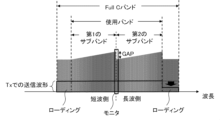
- FIG. 11A is a graph for explaining amplification characteristics of an optical amplifier in an optical transmission system according to the fifth embodiment of the invention.
- the horizontal axis indicates wavelength, and the vertical axis indicates relative spectral intensity.
- the output power of the channel with the longest wavelength in the first subband and the output power of the channel with the shortest wavelength in the second subband when the output of the pumping light source of the optical amplifier is 100%
- An optical transmission system is designed so that a gap (GAP) is not created in .
- GAP gap
- the output of the pumping light source of the optical amplification section is reduced from 100% to 82%, the output power of the channel with the longest wavelength in the first subband and the channel with the shortest wavelength in the second subband are , the output waveform after passing through the equalizer has a gap (GAP) of about 0.4 dB as shown in FIG. 11A.
- GAP gap
- control for reducing the loading amount of wavelengths longer than the second subband specifically, to attenuate the dummy light of wavelengths longer than the second subband.
- the gap (GAP) can be filled by controlling to attenuate eight waves of the dummy light.
- FIG. 11B is a graph for explaining the amplification characteristics of the optical amplifier in the optical transmission system according to the fifth embodiment of the invention.
- Attenuation applied to the loading wavelength at the terminal station 12A terminal station Tx on the transmitting side
- the plurality of repeaters 13 connected in series the same input waveform as that of the optical amplification section of the first-stage repeater 13 is input to the optical amplification section of the repeater 13 in the subsequent stage.
- each stage of the plurality of repeaters 13 connected in series can fill the gaps and perform optical amplification.
- the output is controlled to reduce the loading amount of wavelengths longer than the second subband, specifically, to attenuate the dummy light of wavelengths longer than the second subband.
- the power gap can be made smaller.
- control of the loading amount according to the second to fourth embodiments described above and the control of the loading amount according to the fifth embodiment can be used together.
- control to stop dummy light having a wavelength longer than the second subband as in the second embodiment and control to attenuate dummy light having a wavelength longer than the second subband as in the present embodiment can be used together.
- Control for stopping dummy light having a wavelength longer than that of the second subband as in the second embodiment corresponds to coarse adjustment.
- the control to reduce the number of loadings of wavelengths longer than the second subband corresponds to coarse adjustment.
- the control of attenuating dummy light having a wavelength longer than that of the second subband as in this embodiment corresponds to fine adjustment.
- the intermediate gap amount for adjustment (coarse adjustment) of the intermittent gap amount shown in FIG. Adjustment (fine adjustment) of the amount becomes possible.
- This embodiment is an embodiment using the configuration of the optical transmission system shown in FIG. 2A and FIG. 3 as in the second to fourth embodiments. is characterized by the control method of In this embodiment, the configuration of the optical transmission system shown in FIG. 2A and FIG. 3 is used, and the description of the configuration is omitted.
- FIG. 12 is a graph for explaining the control method of the optical transmission system according to the sixth embodiment of the present invention.
- the terminal station 12A increases the output power of wavelength multiplexed signal light and dummy light for the Full C band.
- FIG. 12 of the Full C band, dummy light is output to a band with a shorter wavelength than the first subband, and dummy light is output to a band with a shorter wavelength than the second subband.
- FIG. 12 shows a state in which the output power of the dummy light is also increased.
- the output power of the channel with the longest wavelength among the first sub-bands on the relatively short wavelength side is monitored,
- the output power of the channel with the shortest wavelength in the second sub-band on the longer wavelength side is monitored.
- a control signal is transmitted so that the gap between the output power of the channel with the longest wavelength in the first subband and the output power of the channel with the shortest wavelength in the second subband is reduced. do.
- control is assumed to attenuate the wavelength multiplexed signal light of the second subband and change the loading amount. More specifically, in addition to control to reduce the loading amount of wavelengths longer than the second subband as in the fifth embodiment, the wavelength transmitted by the terminal station 12A (terminal station Tx on the transmitting side) Of the multiplexed signal light, control is performed to attenuate the wavelength multiplexed signal light of the second sub-band on the longer wavelength side as a whole. This control increases the amplification amount of the optical amplifier for the second subband and increases the gain of the optical amplifier.
- the output power of each signal light of the wavelength multiplexed signal light in the second subband increases, and the output power of the channel with the longest wavelength in the first subband and the output power of the channel in the second subband can reduce the gap with the output power of the channel with the shortest wavelength.
- control is performed to reduce the loading amount of wavelengths longer than the second subband, specifically dummy light of wavelengths longer than the second subband.
- the output power gap can be reduced by such control as attenuation.
- the wavelength multiplexed signal light of the second subband on the longer wavelength side is entirely attenuated. are controlling. Amplification of the optical amplifier section for the second subband by controlling the overall input signal strength of the second subband as well as adjusting the amount of loading of wavelengths longer than the second subband. The amount increases and the gain of the optical amplifier increases. As a result, the output power gap can be made smaller.
- this embodiment can also be used in combination with the control of the loading amount according to the above-described second to fourth embodiments.
- control can be used in combination.
- FIG. 5B is a graph for explaining a modification of the optical transmission system control method according to the second embodiment of the present invention.
- the band used from the start of operation of the optical transmission system is shifted to the short wavelength side of the Full C band and the loading is provided on the long wavelength side.
- the loading is provided on the short wavelength side of the first subband and the loading is provided on the long wavelength side of the second subband, whereas in FIG.
- the loading is provided on the long wavelength side of the second subband.
- the difference is that only loading is provided.
- SC-EDFAs Single Core-Erbium doped Optical Fiber Amplifiers
- one or more individual core excitation type MC-EDFAs Multi-Core-Erbium doped optical fiber amplifiers
- MC-EDFAs Multi-Core-Erbium doped optical fiber amplifiers
- one or more hybrid MC-EDFAs using both cladding collective pumping and core individual pumping can be used.
- FIG. 8 of Patent Document 2 proposes an optical amplifier using a plurality of single-core optical fibers.
- Each of the plurality of single-core optical fibers has a configuration including a single core doped with rare earth ions and a clad surrounding the single core.
- 4 and 6 of Patent Document 2 propose an optical amplifier using a multi-core optical fiber.
- This multi-core optical fiber has a configuration including a plurality of cores doped with rare earth ions and a clad surrounding the plurality of cores.
- the repeater divides the wavelength multiplexed signal light into a plurality of subbands containing signal light of a plurality of wavelength bands, and after amplifying the divided plurality of subbands by a plurality of corresponding optical amplifiers, an optical amplifier for combining the amplified subbands;
- the divided plurality of sub-bands includes a first relatively short wavelength sub-band and a second relatively long wavelength sub-band;
- the control signal instructs the terminal station on the transmission side to change the loading amount.
- the optical transmission system according to appendix 1. (Appendix 3) The control signal instructs the terminal station on the transmission side to reduce the loading amount of wavelengths longer than the second subband.
- the optical transmission system according to appendix 2. (Appendix 4) The control signal instructs the terminal station on the transmission side to reduce the loading amount of wavelengths longer than the second subband, When the gap is not sufficiently reduced even by reducing the loading amount of the long wavelength, the terminal station on the transmitting side is further instructed to increase the loading amount of the wavelength shorter than the first subband. is a The optical transmission system according to appendix 3.
- the terminal station on the transmission side generates the wavelength-multiplexed signal light by wavelength-multiplexing the signal light and the dummy light, The control of the loading amount is performed by increasing or decreasing the channel of the dummy light at the terminal station on the transmission side.
- the optical transmission system according to any one of Appendices 2 to 8. (Appendix 10) By moving the channel with the shortest wavelength among the plurality of sub-bands to the short wavelength side of the used band, A large amount of loading is ensured for wavelengths longer than the second subband, The optical transmission system according to appendix 3.
- the plurality of optical amplifiers are two or more single-core impurity-doped optical fiber amplifiers. 11.
- the optical transmission system according to any one of appendices 1 to 10. The plurality of optical amplification units are one or more multi-core impurity-doped optical fiber amplifiers, 11.
- the optical transmission system according to any one of appendices 1 to 10. (Appendix 13)
- the plurality of optical amplifiers are hybrid multi-core impurity-doped optical fiber amplifiers that use one or more cladding collective pumping and core individual pumping together. 11.
- a pair of terminal stations that mutually transmit and receive wavelength division multiplexed (WDM) signal light, an optical fiber that propagates the wavelength division multiplexed signal light transmitted and received by the pair of terminal stations, and at least one inserted into the optical fiber A control method for an optical transmission system including one repeater, The repeater divides the wavelength multiplexed signal light into a plurality of subbands containing signal light of a plurality of wavelength bands, and after amplifying the divided plurality of subbands by a plurality of corresponding optical amplifiers, combining the amplified sub-bands, The divided plurality of sub-bands includes a first sub-band on the relatively short wavelength side and a second sub-band on the relatively long wavelength side, Received by the terminal station on the receiving side of the pair of terminal stations, monitoring the output power of the channel with the longest wavelength in the first subband and the output power of the channel with the shortest wavelength in the second subband; The wavelength multiplexed signal light so that the gap between the output power of the channel
- the control signal instructs the terminal station on the transmission side to reduce the power of dummy light having a wavelength longer than that of the second subband. 16.
- the control method of the optical transmission system according to appendix 15. instructs the terminal station on the transmission side to reduce the power of the signal light in the wavelength band divided into the second subbands. 19.
- the method of controlling an optical transmission system according to appendix 18. instructs the terminal station on the transmission side to increase the loading amount of wavelengths shorter than the first subband. 16.
- the control signal instructs the terminal station on the transmission side to change the loading amount of the band between the first subband and the second subband. be, 16.
- the terminal station on the transmission side generates the wavelength-multiplexed signal light by wavelength-multiplexing the signal light and the dummy light, The control of the loading amount is performed by increasing or decreasing the channel of the dummy light at the terminal station on the transmission side. 22.
- optical fiber 12A, 12B, 102A, 102B terminal station 13 103 repeater 14, 104 demultiplexer 15 1 to 15 m , 105 1 to 105 m optical amplifier 16, 106 multiplexer 121, 121, 123 wave section 124 multiplexing means 125 demultiplexing means 126, 127, 128 demultiplexing section 21 output gap monitor 22 loading control device 30 network management system 108 monitor section 109 control section
Landscapes
- Engineering & Computer Science (AREA)
- Computer Networks & Wireless Communication (AREA)
- Signal Processing (AREA)
- Physics & Mathematics (AREA)
- Electromagnetism (AREA)
- Optical Communication System (AREA)
Priority Applications (3)
| Application Number | Priority Date | Filing Date | Title |
|---|---|---|---|
| JP2023565729A JP7687441B2 (ja) | 2021-12-07 | 2021-12-07 | 光伝送システム、および光伝送システムの制御方法 |
| US18/711,149 US20250038847A1 (en) | 2021-12-07 | 2021-12-07 | Optical transmission system and method for controlling optical transmission system |
| PCT/JP2021/044904 WO2023105625A1 (ja) | 2021-12-07 | 2021-12-07 | 光伝送システム、および光伝送システムの制御方法 |
Applications Claiming Priority (1)
| Application Number | Priority Date | Filing Date | Title |
|---|---|---|---|
| PCT/JP2021/044904 WO2023105625A1 (ja) | 2021-12-07 | 2021-12-07 | 光伝送システム、および光伝送システムの制御方法 |
Publications (1)
| Publication Number | Publication Date |
|---|---|
| WO2023105625A1 true WO2023105625A1 (ja) | 2023-06-15 |
Family
ID=86729901
Family Applications (1)
| Application Number | Title | Priority Date | Filing Date |
|---|---|---|---|
| PCT/JP2021/044904 Ceased WO2023105625A1 (ja) | 2021-12-07 | 2021-12-07 | 光伝送システム、および光伝送システムの制御方法 |
Country Status (3)
| Country | Link |
|---|---|
| US (1) | US20250038847A1 (https=) |
| JP (1) | JP7687441B2 (https=) |
| WO (1) | WO2023105625A1 (https=) |
Cited By (1)
| Publication number | Priority date | Publication date | Assignee | Title |
|---|---|---|---|---|
| CN117354653A (zh) * | 2023-12-05 | 2024-01-05 | 华海通信技术有限公司 | 一种海缆系统带宽复用方法及海缆系统 |
Citations (5)
| Publication number | Priority date | Publication date | Assignee | Title |
|---|---|---|---|---|
| JP2001053686A (ja) * | 1999-08-12 | 2001-02-23 | Fujitsu Ltd | 複合光増幅装置、n波長帯域WDM方式光信号送信装置、光伝送システムおよび光増幅方法 |
| JP2002009707A (ja) * | 2000-06-21 | 2002-01-11 | Sumitomo Electric Ind Ltd | 光伝送システムおよび光伝送方法 |
| JP2006066862A (ja) * | 2004-07-28 | 2006-03-09 | Fujitsu Ltd | 波長多重信号光の増幅方法および光増幅器 |
| WO2017170008A1 (ja) * | 2016-03-30 | 2017-10-05 | 日本電気株式会社 | 励起光源装置および利得等化方法 |
| WO2020137820A1 (ja) * | 2018-12-27 | 2020-07-02 | 日本電気株式会社 | 光増幅器、光増幅器の等化方法、および伝送システム |
-
2021
- 2021-12-07 WO PCT/JP2021/044904 patent/WO2023105625A1/ja not_active Ceased
- 2021-12-07 US US18/711,149 patent/US20250038847A1/en active Pending
- 2021-12-07 JP JP2023565729A patent/JP7687441B2/ja active Active
Patent Citations (5)
| Publication number | Priority date | Publication date | Assignee | Title |
|---|---|---|---|---|
| JP2001053686A (ja) * | 1999-08-12 | 2001-02-23 | Fujitsu Ltd | 複合光増幅装置、n波長帯域WDM方式光信号送信装置、光伝送システムおよび光増幅方法 |
| JP2002009707A (ja) * | 2000-06-21 | 2002-01-11 | Sumitomo Electric Ind Ltd | 光伝送システムおよび光伝送方法 |
| JP2006066862A (ja) * | 2004-07-28 | 2006-03-09 | Fujitsu Ltd | 波長多重信号光の増幅方法および光増幅器 |
| WO2017170008A1 (ja) * | 2016-03-30 | 2017-10-05 | 日本電気株式会社 | 励起光源装置および利得等化方法 |
| WO2020137820A1 (ja) * | 2018-12-27 | 2020-07-02 | 日本電気株式会社 | 光増幅器、光増幅器の等化方法、および伝送システム |
Cited By (2)
| Publication number | Priority date | Publication date | Assignee | Title |
|---|---|---|---|---|
| CN117354653A (zh) * | 2023-12-05 | 2024-01-05 | 华海通信技术有限公司 | 一种海缆系统带宽复用方法及海缆系统 |
| CN117354653B (zh) * | 2023-12-05 | 2024-02-06 | 华海通信技术有限公司 | 一种海缆系统带宽复用方法及海缆系统 |
Also Published As
| Publication number | Publication date |
|---|---|
| JP7687441B2 (ja) | 2025-06-03 |
| US20250038847A1 (en) | 2025-01-30 |
| JPWO2023105625A1 (https=) | 2023-06-15 |
Similar Documents
| Publication | Publication Date | Title |
|---|---|---|
| JP4551007B2 (ja) | ラマン増幅器およびそれを用いた光伝送システム | |
| US6885499B1 (en) | Optical amplifying apparatus for amplifying wide-wavelength-band light, optical sending apparatus, optical transmission system, and optical amplifying method | |
| EP1248392B1 (en) | Optical amplifier device and bidirectional wavelength division multiplexing optical communication system using the same | |
| US8774624B2 (en) | Optical transmission apparatus and optical communication system | |
| JP2002057624A (ja) | 波長多重光通信システムおよび波長多重光通信方法 | |
| JP2002374024A (ja) | 光増幅器 | |
| JP2001251006A (ja) | 分布型光増幅装置および該方法ならびに光通信システム | |
| JP2003124881A (ja) | 光伝送装置および光伝送システム | |
| JP5724416B2 (ja) | 光伝送装置および光伝送システム | |
| US20040240042A1 (en) | Optical amplifier, communication system and method for control tilt of a communication system | |
| US7075709B2 (en) | Optical transmission system, optical repeater, and optical transmission method | |
| EP4038771B1 (en) | Optical amplifiers that support gain clamping and optionally power loading | |
| JP4659498B2 (ja) | 光伝送装置 | |
| US7242519B2 (en) | Raman amplifier and optical transmission system using the same | |
| US7769302B1 (en) | Method and apparatus for adjusting for polarization-induced, optical signal transients | |
| JP7687441B2 (ja) | 光伝送システム、および光伝送システムの制御方法 | |
| Rapp | Amplifiers in multi–band scenarios—output power requirements, control and performance characteristics | |
| EP2974082A1 (en) | Tilt control through optical pump power adjustment | |
| JP2004104473A (ja) | 光増幅中継器 | |
| JPH08204647A (ja) | 光中継伝送装置および光通信方法 | |
| JP2009164565A (ja) | 利得等化器、光増幅器および光増幅方法 | |
| JP7589640B2 (ja) | 光増幅装置、光伝送システム、および光増幅方法 | |
| US6456425B1 (en) | Method and apparatus to perform lumped raman amplification | |
| WO2022152115A1 (zh) | 产生假光信号的装置、方法以及可重构光分插复用器 | |
| JP4695713B2 (ja) | ラマン増幅器およびそれを用いた光伝送システム |
Legal Events
| Date | Code | Title | Description |
|---|---|---|---|
| 121 | Ep: the epo has been informed by wipo that ep was designated in this application |
Ref document number: 21967129 Country of ref document: EP Kind code of ref document: A1 |
|
| WWE | Wipo information: entry into national phase |
Ref document number: 18711149 Country of ref document: US |
|
| WWE | Wipo information: entry into national phase |
Ref document number: 2023565729 Country of ref document: JP |
|
| NENP | Non-entry into the national phase |
Ref country code: DE |
|
| 122 | Ep: pct application non-entry in european phase |
Ref document number: 21967129 Country of ref document: EP Kind code of ref document: A1 |