WO2023105625A1 - Optical transmission system and method for controlling optical transmission system - Google Patents
Optical transmission system and method for controlling optical transmission system Download PDFInfo
- Publication number
- WO2023105625A1 WO2023105625A1 PCT/JP2021/044904 JP2021044904W WO2023105625A1 WO 2023105625 A1 WO2023105625 A1 WO 2023105625A1 JP 2021044904 W JP2021044904 W JP 2021044904W WO 2023105625 A1 WO2023105625 A1 WO 2023105625A1
- Authority
- WO
- WIPO (PCT)
- Prior art keywords
- wavelength
- subband
- transmission system
- optical transmission
- optical
- Prior art date
Links
Images


Classifications
-
- H—ELECTRICITY
- H04—ELECTRIC COMMUNICATION TECHNIQUE
- H04B—TRANSMISSION
- H04B10/00—Transmission systems employing electromagnetic waves other than radio-waves, e.g. infrared, visible or ultraviolet light, or employing corpuscular radiation, e.g. quantum communication
- H04B10/29—Repeaters
- H04B10/291—Repeaters in which processing or amplification is carried out without conversion of the main signal from optical form
- H04B10/293—Signal power control
Definitions
- the present invention relates to an optical transmission system and the like, and more particularly to an optical transmission system and the like using an optical fiber as a transmission line.
- optical transmission system using an optical fiber as a transmission line is known.
- wavelength bands such as C-band (Conventional Band) and L-band (Long Wave Band) are used as optical communication wavelength bands.
- the C-band wavelength band is 1530 nm to 1565 nm
- the L-band wavelength band is 1565 nm to 1625 nm.
- the optical fiber has a high light transmittance. In other words, the transmission loss of the optical fiber is low in the C-band wavelength band. Therefore, the C-band wavelength band is suitable for long-distance transmission.
- Such an optical transmission system includes, for example, a pair of terminal stations for transmission and reception, an optical fiber as a transmission line connecting the pair of terminal stations, and a plurality of repeaters for relaying the optical fibers. be done.
- Each of the plurality of repeaters includes an optical amplification section that amplifies signal light that attenuates while propagating through a long-distance optical fiber.
- An impurity-doped optical fiber amplifier that amplifies the signal light itself is used as the optical amplifier.
- This impurity-doped optical fiber amplifier includes an EDFA (Erbium-Doped Optical Fiber Amplifier) in which an optical fiber is doped with erbium (Er) ions, which are an example of rare earth ions, as impurities.
- EDFA Erbium-Doped Optical Fiber Amplifier
- Impurity-doped optical fiber amplifiers generally have a large gain for signal light with a long wavelength and a small gain for signal light with a short wavelength in the wavelength band of the signal light to be amplified, as a tendency of amplification characteristics.
- a repeater inserted into an optical fiber is designed so that the output level of signal light with a short wavelength in the wavelength band of signal light to be input and amplified exceeds a predetermined level.
- the gain of the fiber amplifier is adjusted.
- an equalizer connected to the next stage of the impurity-doped optical fiber amplifier cuts off the portion exceeding the predetermined level. , equalization processing is performed to equalize the output levels.
- the portion cut by the equalization processing of this equalizer does not contribute to the optical transmission through the optical fiber, resulting in energy loss.
- An optical transmission system capable of reducing this energy loss is desired.
- Patent Document 1 relates to a method for amplifying wavelength division multiplexing (WDM) signal light.
- WDM wavelength division multiplexing
- wavelength multiplexed signal light is split into signal lights of a plurality of wavelength bands by a demultiplexer.
- An amplification method has been proposed in which signal lights of respective wavelength bands are multiplexed by a multiplexer.
- part of the signal light in each wavelength band amplified by the optical amplifier is split, the power of the split light is measured, and the gain of the optical amplifier is calculated based on the measurement result. are individually adjusted so that the wavelength-to-wavelength deviation of the optical output level generated in each optical amplifier is within a preset range.
- wavelength multiplexed signal light is split into signal lights of a plurality of wavelength bands by a demultiplexing device, and the split signal lights of each wavelength band are sent to respective optical amplifiers.
- the energy loss due to the equalization processing of the equalizer when applying a configuration in which the amplified signal light of each wavelength band is multiplexed by a multiplexing device after amplification (FIG. 13B).
- the wavelength of signal light in the wavelength band amplified by each optical amplifier is Band width narrows.
- the difference between the gain of the signal light having a long wavelength and the gain of the signal light having a short wavelength becomes small.
- the gain of the optical amplifier is adjusted so that the output level of the signal light with the short wavelength out of the wavelength band of the signal light input and amplified by each optical amplifier exceeds the predetermined level, the above predetermined level cannot be achieved. becomes smaller.
- wavelength-multiplexed signal light is split into signal lights of a plurality of wavelength bands by a demultiplexing device, and the split signal lights of each wavelength band are amplified by corresponding optical amplifiers.
- a new problem of a configuration in which, after amplification, the amplified signal light of each wavelength band is multiplexed by a multiplexing device will be examined.
- the energy loss caused by the gain variation that occurs in the optical amplification of wideband wavelength multiplexed signal light can be reduced by splitting the wavelength multiplexed signal light into signal lights of a plurality of wavelength bands with a demultiplexing device, as proposed in Patent Document 1.
- a demultiplexing device as proposed in Patent Document 1.
- the permissible range for standard deviation fluctuations in output intensity due to deterioration over time is about 0.03 dB per amplifier, so the gap must be kept within 0.03 dB. Therefore, filling the output intensity gap caused by aged deterioration is a challenge.
- An object of the present invention is to provide an optical transmission system with a wide band and small gain variation, and a control method thereof, in view of the above-mentioned problems.
- an optical transmission system provides a pair of terminal stations for mutually transmitting and receiving wavelength division multiplexed (WDM) signal light, and propagating the wavelength division multiplexed signal light transmitted and received by the pair of terminal stations.
- WDM wavelength division multiplexed
- An optical transmission system comprising an optical fiber and at least one repeater inserted into the optical fiber;
- the repeater divides the wavelength multiplexed signal light into a plurality of subbands containing signal light of a plurality of wavelength bands, and after amplifying the divided plurality of subbands by a plurality of corresponding optical amplifiers, an optical amplifier for combining the amplified subbands;
- the divided plurality of sub-bands includes a first sub-band on the relatively short wavelength side and a second sub-band on the relatively long wavelength side, Received by the terminal station on the receiving side of the pair of terminal stations, a monitor unit for monitoring the output power of the channel with the longest wavelength in the first subband and the output power of the channel with the shortest wavelength in the second subband;
- the wavelength multiplexed signal light so that the gap between the output power of the channel with the longest wavelength in the first subband and the output power of the channel with the shortest wavelength in the second subband is reduced. and a control unit that transmits a control signal
- a control method for an optical transmission system includes a pair of terminal stations that mutually transmit and receive wavelength division multiplexed (WDM) signal light, an optical fiber that propagates the wavelength division multiplexed signal light transmitted and received by the pair of terminal stations, and a method of controlling an optical transmission system comprising at least one repeater inserted;
- the repeater divides the wavelength multiplexed signal light into a plurality of subbands containing signal light of a plurality of wavelength bands, and after amplifying the divided plurality of subbands by a plurality of corresponding optical amplifiers, combining the amplified sub-bands,
- the divided plurality of sub-bands includes a first sub-band on the relatively short wavelength side and a second sub-band on the relatively long wavelength side, Received by the terminal station on the receiving side of the pair of terminal stations, monitoring the output power of the channel with the longest wavelength in the first subband and the output power of the channel with the shortest wavelength in the second subband;
- the wavelength multiplexed signal light so that the
- the present invention can provide an optical transmission system with a wide band and small gain variation, and a control method thereof.
- FIG. 1 is a block diagram illustrating an optical transmission system according to an embodiment of the generic concept of the present invention
- FIG. 1B is a block diagram for explaining the configuration of the repeater in FIG. 1A
- FIG. 1 is a block diagram illustrating an optical transmission system according to a first embodiment of the invention
- FIG. 2B is a block diagram for explaining the configuration and amplification characteristics of the repeater of FIG. 2A
- FIG. 4 is a graph for explaining the basic principle of amplification characteristics of an optical amplifier
- 2B is a block diagram for explaining a more specific configuration of the optical transmission system of FIG. 2A
- FIG. 3 is a graph for explaining amplification characteristics of an optical amplifier included in FIG. 2B
- FIG. 10 is a graph for explaining the control method of the optical transmission system according to the second embodiment of the present invention
- FIG. 9 is a graph for explaining a modified example of the control method for the optical transmission system according to the second embodiment of the present invention
- 4 is a graph for explaining effects of the embodiment of the present invention
- FIG. 10 is a graph for explaining the control method of the optical transmission system according to the second embodiment of the present invention
- FIG. 10 is a graph for explaining the control method of the optical transmission system according to the second embodiment of the present invention
- FIG. FIG. 10 is a graph for explaining the control method of the optical transmission system according to the second embodiment of the present invention
- FIG. FIG. 11 is a graph for explaining a control method for an optical transmission system according to a third embodiment of the present invention
- FIG. 10 is a graph for explaining a control method for an optical transmission system according to a fourth embodiment of the present invention
- FIG. FIG. 11 is a graph for explaining a control method for an optical transmission system according to a fifth embodiment of the present invention
- FIG. FIG. 11 is a graph for explaining amplification characteristics of an optical amplifier in an optical transmission system according to a fifth embodiment of the present invention
- FIG. FIG. 11 is a graph for explaining amplification characteristics of an optical amplifier in an optical transmission system according to a fifth embodiment of the present invention
- FIG. FIG. 11 is a graph for explaining a control method for an optical transmission system according to a sixth embodiment of the present invention
- FIG. 2 is a conceptual diagram for explaining amplification characteristics of an optical amplifier of the background art and energy loss due to equalization processing
- FIG. 2 is a conceptual diagram for explaining amplification characteristics of an optical amplifier of the background art and energy loss due to equalization processing, assuming a case where the configuration proposed by Patent Document 1 is applied
- 13B is a graph for explaining amplification characteristics when it is assumed that the optical amplifier of FIG. 13B has changed with time;
- FIG. 1A is a block diagram illustrating an optical transmission system according to a generic embodiment of the present invention.
- FIG. 1B is a block diagram for explaining the configuration of the repeater of FIG. 1A.
- the optical transmission system of FIG. 1A is, for example, a system that includes terminal stations on land and optical fibers that connect the terminal stations and propagate wavelength multiplexed signal light.
- a submarine cable system using a submarine cable as the optical fiber is assumed.
- the optical transmission system of FIG. 1A includes terminal stations 102A and 102B as an example of a pair of terminal stations that mutually transmit and receive wavelength division multiplexed (WDM) signal light, and the terminal stations 102A and 102B transmit and receive wavelength multiplexed signal light. and at least one repeater 103 inserted into the optical fiber 101 .
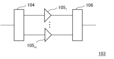
- the repeater 103 in FIG. 1A includes a demultiplexer 104, a plurality of optical amplifiers 105 1 to 105 m (where m is an integer of 2 or more), a multiplexer 106, including.
- the demultiplexer 104 divides the wavelength multiplexed signal light input to the repeater 103 into a plurality of subbands containing signal lights of a plurality of wavelength bands.
- a plurality of optical amplifiers 105 1 to 105 m each amplify the wavelength multiplexed signal light divided into a plurality of subbands.
- the plurality of optical amplifiers 105 1 to 105 m are optical amplifiers typified by EDFAs (erbium-doped optical fiber amplifiers), which amplify and output optical signals using pumping light.
- the multiplexer 106 multiplexes and outputs the wavelength multiplexed signal lights amplified by the optical amplifiers 105 1 to 105 m .
- the plurality of subbands includes at least a first subband on the relatively short wavelength side and a second subband on the relatively long wavelength side.
- a monitor section 108 monitors the output power of the channel with the shortest wavelength among the channels.
- the optical transmission system of FIG. 1A further has a small gap between the output power of the channel with the longest wavelength in the first subband and the output power of the channel with the shortest wavelength in the second subband.
- a control unit 109 for transmitting a control signal to a terminal station on the transmission side that transmits the wavelength multiplexed signal light.
- the monitor unit 108 monitors the output power of the channel with the longest wavelength among the first subbands on the relatively short wavelength side, and monitors the output power of the second channel on the relatively long wavelength side. The output power of the channel with the shortest wavelength among the subbands is monitored.
- control unit 109 controls the output power of the channel with the longest wavelength in the first subband and the output power of the channel with the shortest wavelength in the second subband so that the gap between the output power and the channel with the shortest wavelength becomes smaller.
- a control signal that reduces this gap is transmitted to the terminal station on the transmission side that transmits the wavelength multiplexed signal light.
- the terminal station on the transmitting side changes the state regarding transmission of wavelength division multiplexing (WDM) signal light.
- WDM wavelength division multiplexing
- the optical transmission system of FIG. 1A even if the optical amplifier or the like included in the repeater 103 changes over time after the start of operation, the output power of the channel with the longest wavelength in the first subband and the above By controlling to reduce the gap between the output power of the channel with the shortest wavelength in the second subband, variations in the amplification characteristics of the optical amplifier included in the repeater 103 are reduced, and the energy utilization efficiency is improved.
- the optical transmission system can be realized and the performance of the optical transmission system can be maintained. A more specific optical transmission system and its control method will be described below.
- FIG. 2A is a block diagram illustrating an optical transmission system according to the first embodiment of the invention.
- FIG. 2B is a block diagram for explaining the configuration and amplification characteristics of the repeater in FIG. 2A.
- FIG. 2C is a graph for explaining the basic principle of amplification characteristics of an optical amplifier.
- FIG. 4 is a graph for explaining amplification characteristics of the optical amplifier included in FIG. 2B.
- the optical transmission system of FIG. 2A includes a terminal station 12A (transmitting-side terminal station Tx) that transmits wavelength-multiplexed (WDM) signal light, and a terminal station 12B (transmitting-side terminal station Rx) that receives the wavelength-multiplexed signal light. , and an optical fiber 11 that propagates wavelength multiplexed signal light transmitted and received by the terminal stations 12A and 12B. Furthermore, the optical transmission system of FIG. 2A includes at least one repeater 13 inserted into this optical fiber 11 . Note that FIG. 2A shows an example in which seven repeaters 13 are inserted into the optical fiber 11 .
- the repeater 13 of FIG. 2A includes a demultiplexer 14, a plurality of optical amplifiers 15 1 to 15 m (where m is an integer of 2 or more), a multiplexer 16, including.
- the demultiplexer 14 divides the wavelength multiplexed signal light input to the repeater 13 into a plurality of subbands containing signal lights of a plurality of wavelength bands.
- a plurality of optical amplifiers 15 1 to 15 m amplifies wavelength multiplexed signal lights divided into a plurality of subbands.
- the plurality of optical amplifiers 15 1 to 15 m are optical amplifiers represented by EDFAs (erbium-doped optical fiber amplifiers), and are optical amplifiers that amplify and output optical signals using pumping light.
- the multiplexer 16 multiplexes and outputs the wavelength multiplexed signal lights amplified by the optical amplifiers 15 1 to 15 m .
- the plurality of subbands includes at least a first subband on the relatively short wavelength side and a second subband on the relatively long wavelength side.
- the output power of the channel with the longest wavelength in the first subband received by the terminal station Rx on the receiving side and the channel with the longest wavelength in the second subband are An output gap monitor 21 is included to monitor the short channel output power.
- the optical transmission system of FIG. 2A further has a small gap between the output power of the channel with the longest wavelength in the first subband and the output power of the channel with the shortest wavelength in the second subband.
- a loading control device 22 for transmitting a control signal to the terminal station Tx on the transmission side.
- the output gap monitor 21 monitors the output power of the channel with the longest wavelength among the first subbands on the relatively short wavelength side, and monitors the output power of the second channel on the relatively long wavelength side. monitor the output power of the channel with the shortest wavelength among the subbands of .
- the loading control device 22 reduces the gap between the output power of the channel with the longest wavelength in the first subband and the output power of the channel with the shortest wavelength in the second subband. , to send control signals.
- a control signal that reduces this gap is transmitted to the terminal station Tx on the transmission side.
- the terminal station Tx on the transmitting side changes the state regarding transmission of wavelength multiplexed signal light.
- the gap between the output power of the channel with the longest wavelength in the first subband and the output power of the channel with the shortest wavelength in the second subband becomes smaller.
- the gap in the amplification characteristics becomes smaller due to the optical amplification for each divided subband, so that the energy loss due to the equalization process can be reduced.
- FIG. 3 is a block diagram for explaining a more specific configuration of the optical transmission system of FIG. 2A.
- the optical transmission system of FIG. 3 includes a terminal station 12A (transmitting-side terminal station Tx), a terminal station 12B (transmitting-side terminal station Rx) shown in FIG. 2A, and an optical fiber 11 for propagating wavelength multiplexed signal light. , and a network management system 30 .
- the network management system 30 supervises the entire optical transmission system of FIG. 2A, and particularly in this embodiment, shows a configuration for controlling the loading control device 22 based on the output of the output gap monitor 21 . In FIG. 3, illustration of the repeater 13 inserted into the optical fiber 11 is omitted.
- the terminal station Tx on the transmitting side includes a configuration for wavelength-multiplexing the signal light to be transmitted and the dummy light related to loading, and the loading control device 22 .
- the terminal station Tx on the transmission side includes a multiplexing unit 121 for wavelength-multiplexing the signal lights (Sig.1 to Sig.K-1) of channel #1 to channel #K-1, and the signals of channel #K to channel #N. and a multiplexer 122 that wavelength-multiplexes the light (Sig.K to Sig.N).
- N and K are integers satisfying N>K ⁇ 2, for example.
- the channel numbers of channel #1 to channel #N are given in order from the short wavelength side to the long wavelength side.
- the transmission-side terminal station Tx further multiplexes the outputs of the multiplexing units 121, 122, and 123 with a multiplexing unit 123 that wavelength-multiplexes the #1 to #n dummy lights (Rod.1 to Rod.n). It includes multiplexing means 124 and a loading control device 22 that controls the multiplexing section 123 according to an input control signal.
- the loading control device 22 instructs the combining unit 123 to output or stop the dummy lights #1 to #n, or to attenuate the optical power of the dummy lights #1 to #n according to the input control signal. to indicate.
- the terminal station Rx on the receiving side is configured to include a configuration for demultiplexing received signal light and dummy light relating to loading, and an output gap monitor 21 .
- the terminal station Rx on the receiving side includes demultiplexing means 125 for demultiplexing the wavelength multiplexed signal light propagating through the optical fiber 11, and signal light of channel #1 to channel #K-1 (Sig.1 to Sig.K-1 ), and a demultiplexing unit 127 for demultiplexing signal lights of channel #K to channel #N (Sig.K to Sig.N).
- the terminal station Rx on the receiving side includes a demultiplexer 128 that demultiplexes dummy lights #1 to #n, and an output gap monitor 21 .
- Output gap monitor 21 monitors the output power of channel #K-1 signal light (Sig.K-1) output from demultiplexer 126 and the output power of channel #K signal light (Sig.K-1) output from demultiplexer 127. .K) output power and monitor.
- the output gap monitor 21 monitors, for example, the amount of gap between the output power of the signal light (Sig.K-1) of channel #K-1 and the output power of the signal light (Sig.K) of channel #K.
- the signal light (Sig.K-1) of channel #K-1 corresponds to the channel with the longest wavelength in the first subband
- the signal light (Sig.K) of channel #K corresponds to the channel with the longest wavelength. It corresponds to the channel with the shortest wavelength among the two subbands.
- the terminal station Tx on the transmission side has a multiplexing unit 123 that wavelength-multiplexes dummy lights (Rod. It includes a wave means 124 and a loading control device 22 that controls the multiplexing section 123 according to an input control signal.
- the loading control device 22 outputs or stops the dummy lights (Rod.1 to Rod.n) of #1 to #n of the multiplexer 123 to the multiplexer 123 according to the input control signal, or Indicate attenuation of dummy light. Thereby, the loading controller 22 controls the amount of loading in the optical transmission system.
- wavelength division multiplexing (WDM) signal light transmitted from the terminal station 12A propagates through the optical fiber 11 and is received by the terminal station 12B.
- the wavelength-multiplexed signal light which attenuates while propagating through the long-distance optical fiber 11, is amplified by the repeater 13 inserted into the optical fiber 11 to maintain a predetermined level of gain.
- the repeater 13 divides the wavelength-multiplexed signal light into a plurality of subbands containing signal lights of a plurality of wavelength bands. In the repeater 13 of FIG.
- a demultiplexer 14 is provided as means for separating this wavelength multiplexed signal light, and the wavelength multiplexed signal light is divided into a plurality of subbands by the demultiplexer 14 .
- the plurality of subbands are, for example, first to mth subbands (here, m is an integer equal to or greater than 2).
- the wavelength-multiplexed signal light is amplified in the form of an optical signal upon introduction of pumping light.
- FIG. 2C As a characteristic of the optical amplifier, as shown in FIG. 2C, even if the pumping light to be introduced is the same, there is a tendency that the amount of amplification increases for narrowband input signals and decreases for wideband input signals. .
- the divided sub-bands are amplified by the corresponding optical amplifiers 15 1 to 15 m , and then the multiplexed sub-bands are multiplexed by the multiplexer 16 . After the optical transmission system starts operating, it is assumed that the characteristics change (change over time) with the passage of time.
- the optical transmission system of the present embodiment particularly deals with temporal changes related to the amplification characteristics of the plurality of optical amplifiers 15 1 to 15 m .
- the division is made to include one subband and a second subband on the relatively longer wavelength side.
- the first subband is, for example, a subband containing signal light (Sig.1 to Sig.K-1) of channel #1 to channel #K-1
- the second subband is, for example, channel # It is a subband that contains signal light of K to channel #N (Sig.K to Sig.N).
- the signal lights of channel #1 to channel #K-1 (Sig.1 to Sig.K-1) are amplified by the optical amplifier 151 , and the signal lights of channel #K to channel #N are amplified. (Sig.K to Sig.N) are amplified by the optical amplifier 152 and combined by the multiplexer 16 .
- This wavelength-multiplexed signal light propagates through the optical fiber 11 and is received at the terminal station 12B.
- the wavelength multiplexed signal light is demultiplexed by the demultiplexer 125, the demultiplexer 126, and the demultiplexer 127.
- FIG. The output gap monitor 21 monitors the output power of the signal light (Sig.K-1) of channel #K-1, which is the channel with the longest wavelength in the first subband, and the middle wavelength in the second subband. and the output power of the signal light (Sig.K) of channel #K, which is the channel with the shortest wavelength.
- the output power of the signal light (Sig.K-1) of channel #K-1 and the output of the signal light (Sig.K) of channel #K which is the channel with the shortest wavelength in the second subband, If there is a gap between the power and the power, control is performed so that this gap becomes small.
- the output power of the signal light (Sig.K-1) of channel #K-1 and the signal light of channel #K (Sig.K ) the control signal is transmitted to the terminal station 12A on the transmission side that transmits the wavelength multiplexed signal light.
- the output gap monitor 21 transmits a control signal to the loading control device 22, and in FIG. It shows a mode of transmitting a control signal to the loading control device 22 based on the above.
- the loading control device 22 instructs to output or stop the dummy lights #1 to #n (Rod.1 to Rod.n), or to attenuate the dummy lights. Since the optical amplifier has an amplification characteristic as shown in FIG. 2C, by instructing the loading control device 22 to change dummy light from output to stop, stop to output, and output to attenuate, optical amplification of the repeater 13 is controlled. The gains of the sections 15 1 and 15 2 can be individually changed from the terminal station 12A.
- the output gap monitor 21 monitors the signal light (Sig.K -1), and monitor the output power of the signal light (Sig.K) of channel #K, which is the channel with the shortest wavelength in the second sub-band on the relatively long wavelength side. . Furthermore, the output gap monitor 21 in FIG. 2A and the network management system 30 in FIG. A control signal is transmitted so that the gap with the output power becomes small. A control signal that reduces this gap is transmitted to the transmission-side terminal station 12A (transmission-side terminal station Tx) that transmits the wavelength-multiplexed signal light. In particular, this control signal is transmitted to the loading controller 22 of the terminal station 12A on the transmission side that transmits the wavelength multiplexed signal light.
- the terminal station on the transmitting side changes the state regarding transmission of wavelength division multiplexing (WDM) signal light.
- WDM wavelength division multiplexing
- optical amplifiers 15 1 to 15 m included in the repeater 13 change over time after the start of operation, the wavelength is the lowest in the first subband.
- optical amplifiers 15 1 to 15 m It is possible to realize an optical transmission system with improved energy utilization efficiency by reducing variations in the amplification characteristics of the optical transmission system, while maintaining the performance of the optical transmission system.
- the gap between the output power of the channel with the longest wavelength in the first subband and the output power of the channel with the shortest wavelength in the second subband is reduced.
- FIG. 5A is a graph for explaining the control method of the optical transmission system according to the second embodiment of the present invention.
- 7A to 7C are graphs for explaining the control method of the optical transmission system according to the second embodiment of the present invention.
- This embodiment uses the configuration of the optical transmission system shown in FIGS. 2A and 3, and is characterized by the operation of the optical transmission system and the method of controlling the optical transmission system. In this embodiment, the configuration of the optical transmission system shown in FIG. 2A and FIG. 3 is used, and the description of the configuration is omitted.
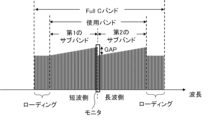
- the Full C band includes a plurality of sub-bands (first sub-band, second sub-band) used for transmission of wavelength multiplexed signal light, and a second sub-band on the shorter wavelength side.
- a band having a shorter wavelength than one subband and a band having a longer wavelength than a second subband on the longer wavelength side are also included.
- the optical transmission system is designed to include multiple channels that will be used at the start of operation, as well as multiple unused channels (dark channels) at the start of operation, assuming future enhancements.
- control is performed such as outputting dummy light to unused channels.
- changes are made such as supplying signal light and stopping dummy light.
- dummy light is output to a band with a shorter wavelength than the first subband, and dummy light is output to a band with a shorter wavelength than the second subband. state.
- the output power of the channel with the longest wavelength among the first sub-bands on the relatively short wavelength side is monitored,
- the output power of the channel with the shortest wavelength in the second sub-band on the longer wavelength side is monitored.
- a control signal is transmitted so that the gap between the output power of the channel with the longest wavelength in the first subband and the output power of the channel with the shortest wavelength in the second subband is reduced. do.
- control is assumed to change the loading amount, as indicated by two arrows in FIG. 7A. More specifically, the control is such that the loading amount of longer wavelengths than the second subband is reduced, for example, by changing from the state shown in FIG. 7A to the state shown in FIG. 7B.
- Control for reducing the loading amount of wavelengths longer than the second subband is, for example, control by the loading control device 22 in FIG. is realized by turning off the dummy light of .
- the narrower the band of the input signal the greater the amplification amount of the optical amplifier, and the higher the gain of the optical amplifier.
- the output power of each signal light of the wavelength multiplexed signal light in the second subband increases, and the output power of the channel with the longest wavelength in the first subband and the output power of the channel in the second subband can reduce the gap with the output power of the channel with the shortest wavelength.
- the output power gap can be reduced.
- the control for reducing the output power gap by stopping the dummy light having a wavelength longer than that of the second subband is the control for stopping the dummy light in the output state, and the control is continued until all the dummy light is stopped. It can be carried out.
- the state shown in FIG. 7B is changed to the state shown in FIG. 7C. It is also conceivable to perform control to increase the loading amount of a wavelength shorter than that of one subband.
- the control for increasing the loading amount of wavelengths shorter than the first subband is, for example, control by the loading control device 22 in FIG. is realized by adding and outputting dummy light.
- the output power gap is reduced by controlling the loading amount of the long wavelength to be smaller than that of the second subband on the long wavelength side.
- the loading amount of wavelengths longer than the second subband is reduced, so that the power consumption related to the dummy light can be reduced, and the light with improved energy utilization efficiency can be obtained.
- a transmission system can be realized and the performance of the optical transmission system can be maintained.
- the control to decrease the loading amount of the longer wavelength than the second sub-band on the long wavelength side in addition to the control to decrease the loading amount of the longer wavelength than the second sub-band on the long wavelength side, the control to increase the loading amount of the short wavelength than the first sub-band on the short wavelength side is performed. can be used together to make the output power gap smaller.
- FIG. 6 is a graph for explaining the effects of the embodiment of the present invention.
- the horizontal axis indicates wavelength, and the vertical axis indicates relative spectral intensity.
- the output power of the channel with the longest wavelength in the first subband and the output power of the channel with the shortest wavelength in the second subband when the output of the pumping light source of the optical amplifier is 100%
- An optical transmission system is designed so that a gap (GAP) is not created in .
- the output of the pumping light source of the optical amplification section is reduced from 100% to 82%, the output power of the channel with the longest wavelength in the first subband and the channel with the shortest wavelength in the second subband are , the output waveform after passing through the equalizer has a gap (GAP) of about 0.4 dB as shown in FIG.
- control to reduce the loading amount of wavelengths longer than the second subband in the case of FIG. can be filled.
- the gap (GAP) can be filled by stopping the four dummy lights L44, L43, L42, and L41 on the longer wavelength side than the second subband.
- the relative spectral intensity of the second sub-band on the long wavelength side increases due to the termination of the dummy lights L40, L39, L38, L37, and L36 on the long wavelength side.
- FIG. 8 is a graph for explaining the control method of the optical transmission system according to the third embodiment of the present invention.
- this embodiment uses the configuration of the optical transmission system shown in FIG. 2A and FIG. There is In this embodiment, the configuration of the optical transmission system shown in FIG. 2A and FIG. 3 is used, and the description of the configuration is omitted.
- the optical transmission system is designed to include multiple channels that will be used at the start of operation, as well as multiple unused channels (dark channels) at the start of operation, assuming future enhancements. be done.
- a change is made such as supplying signal light and stopping dummy light.
- the output power is controlled to reduce the loading amount of the wavelength longer than the second subband as in the second embodiment described above. It is assumed that the control to reduce the gap between and becomes difficult.
- the input signal band is widened with respect to the optical amplification of the first sub-band by controlling the loading amount of the short wavelength to be greater than that of the first sub-band on the short wavelength side.
- the amplification amount of the optical amplifier decreases, and the gain of the optical amplifier for the first subband decreases. This makes it possible to reduce the gap with the output power.
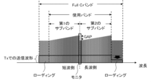
- the control for increasing the loading amount in the short wavelength side from the first sub-band on the short wavelength side is to add the loading amount in the wavelength band shorter than the Full C band as shown in FIG. showing.
- the input signal band is widened with respect to the optical amplification of the first subband, so that the amplification amount of the optical amplifier can be reduced.
- the gain of the optical amplifier in the first subband can be reduced.
- the output power gap can be made smaller by controlling the loading amount of the short wavelength to be greater than that of the first subband on the short wavelength side. At that time, in this embodiment, additional loading is performed outside the Full C band. Specifically, by adding a loading amount to a wavelength band shorter than the Full C band, it is possible to reduce the amplification amount of the optical amplification unit with respect to the optical amplification of the first subband. The gain of the optical amplifier can be lowered. As a result, the output power gap can be made smaller.
- FIG. 9 is a graph for explaining the control method of the optical transmission system according to the fourth embodiment of the present invention. Similar to the second and third embodiments, this embodiment uses the configuration of the optical transmission system shown in FIGS. 2A and 3 described above. is characterized by the control method of In this embodiment, the configuration of the optical transmission system shown in FIG. 2A and FIG. 3 is used, and the description of the configuration is omitted.
- the output power gap is made smaller by controlling the loading amount of longer wavelengths and the loading amount of shorter wavelengths than the divided plurality of subbands.
- the control of the loading amount according to the embodiment of the present invention is not limited to these.
- the bands used are divided into a first sub-band of a shorter wavelength band and a second sub-band of a longer wavelength band.
- the loading amount of the band between the first sub-band and the second sub-band as shown in FIG. 9 is controlled.
- the control signal is transmitted so that the gap between the output power of the channel with the longest wavelength in the first subband and the output power of the channel with the shortest wavelength in the second subband is reduced. .
- wavelength multiplexing of the second sub-band is performed by controlling the loading amount of the band close to the second sub-band among the loading amounts of the band between the first sub-band and the second sub-band.
- the output power of each signal light can be increased.
- the wavelength multiplexed signal of the first sub-band The output power of each optical signal light can be reduced.
- the output power gap can be made smaller by controlling the loading amount of the band between the first subband and the second subband.
- This embodiment is an embodiment using the configuration of the optical transmission system shown in FIG. 2A and FIG. 3 as in the second to fourth embodiments. is characterized by the control method of In this embodiment, the configuration of the optical transmission system shown in FIG. 2A and FIG. 3 is used, and the description of the configuration is omitted.
- FIG. 10 is a graph for explaining the control method of the optical transmission system according to the fifth embodiment of the present invention.
- the terminal station 12A transmitting-side terminal station Tx increases the output power of the wavelength multiplexed signal light and the dummy light for the Full C band.
- the terminal station 12A transmitting-side terminal station Tx
- the terminal station 12A increases the output power of the wavelength multiplexed signal light and the dummy light for the Full C band.
- FIG. 10 of the Full C band, dummy light is output to a band with a shorter wavelength than the first subband, and dummy light is output to a band with a shorter wavelength than the second subband.
- FIG. 10 shows a state in which the output power of the dummy light is also increased.
- the output power of the channel with the longest wavelength among the first sub-bands on the relatively short wavelength side is monitored,
- the output power of the channel with the shortest wavelength in the second sub-band on the longer wavelength side is monitored.
- a control signal is transmitted so that the gap between the output power of the channel with the longest wavelength in the first subband and the output power of the channel with the shortest wavelength in the second subband is reduced. do.
- control is assumed to change the loading amount, as indicated by the arrows in FIG. More specifically, the control is such that the loading amount of wavelengths longer than the second subband is reduced.
- control to attenuate This control increases the amplification amount of the optical amplifier for the second subband and increases the gain of the optical amplifier.
- the output power of each signal light of the wavelength multiplexed signal light in the second subband increases, and the output power of the channel with the longest wavelength in the first subband and the output power of the channel in the second subband can reduce the gap with the output power of the channel with the shortest wavelength.
- FIG. 11A is a graph for explaining amplification characteristics of an optical amplifier in an optical transmission system according to the fifth embodiment of the invention.
- the horizontal axis indicates wavelength, and the vertical axis indicates relative spectral intensity.
- the output power of the channel with the longest wavelength in the first subband and the output power of the channel with the shortest wavelength in the second subband when the output of the pumping light source of the optical amplifier is 100%
- An optical transmission system is designed so that a gap (GAP) is not created in .
- GAP gap
- the output of the pumping light source of the optical amplification section is reduced from 100% to 82%, the output power of the channel with the longest wavelength in the first subband and the channel with the shortest wavelength in the second subband are , the output waveform after passing through the equalizer has a gap (GAP) of about 0.4 dB as shown in FIG. 11A.
- GAP gap
- control for reducing the loading amount of wavelengths longer than the second subband specifically, to attenuate the dummy light of wavelengths longer than the second subband.
- the gap (GAP) can be filled by controlling to attenuate eight waves of the dummy light.
- FIG. 11B is a graph for explaining the amplification characteristics of the optical amplifier in the optical transmission system according to the fifth embodiment of the invention.
- Attenuation applied to the loading wavelength at the terminal station 12A terminal station Tx on the transmitting side
- the plurality of repeaters 13 connected in series the same input waveform as that of the optical amplification section of the first-stage repeater 13 is input to the optical amplification section of the repeater 13 in the subsequent stage.
- each stage of the plurality of repeaters 13 connected in series can fill the gaps and perform optical amplification.
- the output is controlled to reduce the loading amount of wavelengths longer than the second subband, specifically, to attenuate the dummy light of wavelengths longer than the second subband.
- the power gap can be made smaller.
- control of the loading amount according to the second to fourth embodiments described above and the control of the loading amount according to the fifth embodiment can be used together.
- control to stop dummy light having a wavelength longer than the second subband as in the second embodiment and control to attenuate dummy light having a wavelength longer than the second subband as in the present embodiment can be used together.
- Control for stopping dummy light having a wavelength longer than that of the second subband as in the second embodiment corresponds to coarse adjustment.
- the control to reduce the number of loadings of wavelengths longer than the second subband corresponds to coarse adjustment.
- the control of attenuating dummy light having a wavelength longer than that of the second subband as in this embodiment corresponds to fine adjustment.
- the intermediate gap amount for adjustment (coarse adjustment) of the intermittent gap amount shown in FIG. Adjustment (fine adjustment) of the amount becomes possible.
- This embodiment is an embodiment using the configuration of the optical transmission system shown in FIG. 2A and FIG. 3 as in the second to fourth embodiments. is characterized by the control method of In this embodiment, the configuration of the optical transmission system shown in FIG. 2A and FIG. 3 is used, and the description of the configuration is omitted.
- FIG. 12 is a graph for explaining the control method of the optical transmission system according to the sixth embodiment of the present invention.
- the terminal station 12A increases the output power of wavelength multiplexed signal light and dummy light for the Full C band.
- FIG. 12 of the Full C band, dummy light is output to a band with a shorter wavelength than the first subband, and dummy light is output to a band with a shorter wavelength than the second subband.
- FIG. 12 shows a state in which the output power of the dummy light is also increased.
- the output power of the channel with the longest wavelength among the first sub-bands on the relatively short wavelength side is monitored,
- the output power of the channel with the shortest wavelength in the second sub-band on the longer wavelength side is monitored.
- a control signal is transmitted so that the gap between the output power of the channel with the longest wavelength in the first subband and the output power of the channel with the shortest wavelength in the second subband is reduced. do.
- control is assumed to attenuate the wavelength multiplexed signal light of the second subband and change the loading amount. More specifically, in addition to control to reduce the loading amount of wavelengths longer than the second subband as in the fifth embodiment, the wavelength transmitted by the terminal station 12A (terminal station Tx on the transmitting side) Of the multiplexed signal light, control is performed to attenuate the wavelength multiplexed signal light of the second sub-band on the longer wavelength side as a whole. This control increases the amplification amount of the optical amplifier for the second subband and increases the gain of the optical amplifier.
- the output power of each signal light of the wavelength multiplexed signal light in the second subband increases, and the output power of the channel with the longest wavelength in the first subband and the output power of the channel in the second subband can reduce the gap with the output power of the channel with the shortest wavelength.
- control is performed to reduce the loading amount of wavelengths longer than the second subband, specifically dummy light of wavelengths longer than the second subband.
- the output power gap can be reduced by such control as attenuation.
- the wavelength multiplexed signal light of the second subband on the longer wavelength side is entirely attenuated. are controlling. Amplification of the optical amplifier section for the second subband by controlling the overall input signal strength of the second subband as well as adjusting the amount of loading of wavelengths longer than the second subband. The amount increases and the gain of the optical amplifier increases. As a result, the output power gap can be made smaller.
- this embodiment can also be used in combination with the control of the loading amount according to the above-described second to fourth embodiments.
- control can be used in combination.
- FIG. 5B is a graph for explaining a modification of the optical transmission system control method according to the second embodiment of the present invention.
- the band used from the start of operation of the optical transmission system is shifted to the short wavelength side of the Full C band and the loading is provided on the long wavelength side.
- the loading is provided on the short wavelength side of the first subband and the loading is provided on the long wavelength side of the second subband, whereas in FIG.
- the loading is provided on the long wavelength side of the second subband.
- the difference is that only loading is provided.
- SC-EDFAs Single Core-Erbium doped Optical Fiber Amplifiers
- one or more individual core excitation type MC-EDFAs Multi-Core-Erbium doped optical fiber amplifiers
- MC-EDFAs Multi-Core-Erbium doped optical fiber amplifiers
- one or more hybrid MC-EDFAs using both cladding collective pumping and core individual pumping can be used.
- FIG. 8 of Patent Document 2 proposes an optical amplifier using a plurality of single-core optical fibers.
- Each of the plurality of single-core optical fibers has a configuration including a single core doped with rare earth ions and a clad surrounding the single core.
- 4 and 6 of Patent Document 2 propose an optical amplifier using a multi-core optical fiber.
- This multi-core optical fiber has a configuration including a plurality of cores doped with rare earth ions and a clad surrounding the plurality of cores.
- the repeater divides the wavelength multiplexed signal light into a plurality of subbands containing signal light of a plurality of wavelength bands, and after amplifying the divided plurality of subbands by a plurality of corresponding optical amplifiers, an optical amplifier for combining the amplified subbands;
- the divided plurality of sub-bands includes a first relatively short wavelength sub-band and a second relatively long wavelength sub-band;
- the control signal instructs the terminal station on the transmission side to change the loading amount.
- the optical transmission system according to appendix 1. (Appendix 3) The control signal instructs the terminal station on the transmission side to reduce the loading amount of wavelengths longer than the second subband.
- the optical transmission system according to appendix 2. (Appendix 4) The control signal instructs the terminal station on the transmission side to reduce the loading amount of wavelengths longer than the second subband, When the gap is not sufficiently reduced even by reducing the loading amount of the long wavelength, the terminal station on the transmitting side is further instructed to increase the loading amount of the wavelength shorter than the first subband. is a The optical transmission system according to appendix 3.
- the terminal station on the transmission side generates the wavelength-multiplexed signal light by wavelength-multiplexing the signal light and the dummy light, The control of the loading amount is performed by increasing or decreasing the channel of the dummy light at the terminal station on the transmission side.
- the optical transmission system according to any one of Appendices 2 to 8. (Appendix 10) By moving the channel with the shortest wavelength among the plurality of sub-bands to the short wavelength side of the used band, A large amount of loading is ensured for wavelengths longer than the second subband, The optical transmission system according to appendix 3.
- the plurality of optical amplifiers are two or more single-core impurity-doped optical fiber amplifiers. 11.
- the optical transmission system according to any one of appendices 1 to 10. The plurality of optical amplification units are one or more multi-core impurity-doped optical fiber amplifiers, 11.
- the optical transmission system according to any one of appendices 1 to 10. (Appendix 13)
- the plurality of optical amplifiers are hybrid multi-core impurity-doped optical fiber amplifiers that use one or more cladding collective pumping and core individual pumping together. 11.
- a pair of terminal stations that mutually transmit and receive wavelength division multiplexed (WDM) signal light, an optical fiber that propagates the wavelength division multiplexed signal light transmitted and received by the pair of terminal stations, and at least one inserted into the optical fiber A control method for an optical transmission system including one repeater, The repeater divides the wavelength multiplexed signal light into a plurality of subbands containing signal light of a plurality of wavelength bands, and after amplifying the divided plurality of subbands by a plurality of corresponding optical amplifiers, combining the amplified sub-bands, The divided plurality of sub-bands includes a first sub-band on the relatively short wavelength side and a second sub-band on the relatively long wavelength side, Received by the terminal station on the receiving side of the pair of terminal stations, monitoring the output power of the channel with the longest wavelength in the first subband and the output power of the channel with the shortest wavelength in the second subband; The wavelength multiplexed signal light so that the gap between the output power of the channel
- the control signal instructs the terminal station on the transmission side to reduce the power of dummy light having a wavelength longer than that of the second subband. 16.
- the control method of the optical transmission system according to appendix 15. instructs the terminal station on the transmission side to reduce the power of the signal light in the wavelength band divided into the second subbands. 19.
- the method of controlling an optical transmission system according to appendix 18. instructs the terminal station on the transmission side to increase the loading amount of wavelengths shorter than the first subband. 16.
- the control signal instructs the terminal station on the transmission side to change the loading amount of the band between the first subband and the second subband. be, 16.
- the terminal station on the transmission side generates the wavelength-multiplexed signal light by wavelength-multiplexing the signal light and the dummy light, The control of the loading amount is performed by increasing or decreasing the channel of the dummy light at the terminal station on the transmission side. 22.
- optical fiber 12A, 12B, 102A, 102B terminal station 13 103 repeater 14, 104 demultiplexer 15 1 to 15 m , 105 1 to 105 m optical amplifier 16, 106 multiplexer 121, 121, 123 wave section 124 multiplexing means 125 demultiplexing means 126, 127, 128 demultiplexing section 21 output gap monitor 22 loading control device 30 network management system 108 monitor section 109 control section
Abstract
The present invention provides an optical transmission system with a small gain variation in broadband and a control method therefor. Provided is an optical transmission system including a pair of end stations that transmit and receive wavelength division multiplexed (WDM) signal light to and from each other, an optical fiber through which the wavelength division multiplexed signal light transmitted and received by the pair of end stations propagates, and at least one repeater inserted in the optical fiber. The repeater includes an optical amplifier that divides the wavelength division multiplexed signal light into multiple subbands including signal beams in multiple wavelength bands, amplifies the multiple subbands with the corresponding optical amplification units, and then multiplexes the amplified subbands, the multiple subbands obtained by the division including a first subband on a relatively shorter wavelength side and a second subband on a relatively longer wavelength side. There are also included: a monitoring unit that monitors the output power of a channel with the longest wavelength in the first subband and the output power of a channel with the shortest wavelength in the second subband, the channels being received by a receiving end station in the pair of end stations; and a control unit that transmits a control signal to a transmitting end station, which transmits the wavelength division multiplexed signal light, so that a gap between the output power of the channel with the longest wavelength in the first subband and the output power of the channel with the shortest wavelength in the second subband is reduced.
Description
本発明は、光伝送システム等に関し、特に伝送路として光ファイバを用いた光伝送システム等に関する。
The present invention relates to an optical transmission system and the like, and more particularly to an optical transmission system and the like using an optical fiber as a transmission line.
伝送路として光ファイバを用いた光伝送システムが、知られている。この光伝送システムでは、光ファイバの伝送損失などを考慮して、特にC-band(Conventional Band)やL-band(Long Wave Band)といった波長帯域が光通信波長帯として用いられる。ここで、C-bandの波長帯域は1530nm~1565nmであり、L-bandの波長帯域は1565nm~1625nmである。C-bandの波長帯域は、光ファイバの光透過率が高い。これを言い換えると、C-bandの波長帯域は、光ファイバの伝送損失が低い。このため、C-bandの波長帯域は長距離伝送に適している。
An optical transmission system using an optical fiber as a transmission line is known. In this optical transmission system, in consideration of the transmission loss of optical fibers, wavelength bands such as C-band (Conventional Band) and L-band (Long Wave Band) are used as optical communication wavelength bands. Here, the C-band wavelength band is 1530 nm to 1565 nm, and the L-band wavelength band is 1565 nm to 1625 nm. In the C-band wavelength band, the optical fiber has a high light transmittance. In other words, the transmission loss of the optical fiber is low in the C-band wavelength band. Therefore, the C-band wavelength band is suitable for long-distance transmission.
このような光伝送システムは例えば、送受信を行う一対の端局と、この一対の端局間を結ぶ伝送路としての光ファイバと、この光ファイバを中継する複数の中継器と、を含んで構成される。複数の中継器のそれぞれは、長距離の光ファイバを伝播するうちに減衰していく信号光を増幅する光増幅部を含む。この光増幅部としては、信号光そのものを増幅する不純物添加光ファイバ増幅器が用いられている。この不純物添加光ファイバ増幅器としては、不純物として希土類イオンの一例としてのエルビウム(Er)イオンが光ファイバに添加されたEDFA(Erbium-Doped optical Fiber Amplifier)などがある。
Such an optical transmission system includes, for example, a pair of terminal stations for transmission and reception, an optical fiber as a transmission line connecting the pair of terminal stations, and a plurality of repeaters for relaying the optical fibers. be done. Each of the plurality of repeaters includes an optical amplification section that amplifies signal light that attenuates while propagating through a long-distance optical fiber. An impurity-doped optical fiber amplifier that amplifies the signal light itself is used as the optical amplifier. This impurity-doped optical fiber amplifier includes an EDFA (Erbium-Doped Optical Fiber Amplifier) in which an optical fiber is doped with erbium (Er) ions, which are an example of rare earth ions, as impurities.
不純物添加光ファイバ増幅器は、増幅特性の傾向として、一般的に、増幅される信号光の波長帯域において長い波長の信号光の利得が大きく、短い波長の信号光の利得が小さい。光ファイバに挿入される中継器では、この増幅特性の傾向を考慮して、入力され増幅される信号光の波長帯域のうち短い波長の信号光の出力レベルが所定レベルを越えるように不純物添加光ファイバ増幅器の利得が調整される。そして不純物添加光ファイバ増幅器の次段に接続される等化器によって上記所定レベルを越えた部分をカットすることにより、一つの不純物添加光ファイバ増幅器で増幅される信号光の波長帯域の各チャネルにおいて、出力レベルを揃える等化処理が行われる。この等化器の等化処理によってカットされる部分は、光ファイバによる光伝送に寄与しないため、エネルギー損失となる。このエネルギー損失を低減することができる光伝送システムが望まれる。
Impurity-doped optical fiber amplifiers generally have a large gain for signal light with a long wavelength and a small gain for signal light with a short wavelength in the wavelength band of the signal light to be amplified, as a tendency of amplification characteristics. Considering this tendency of the amplification characteristics, a repeater inserted into an optical fiber is designed so that the output level of signal light with a short wavelength in the wavelength band of signal light to be input and amplified exceeds a predetermined level. The gain of the fiber amplifier is adjusted. In each channel of the wavelength band of the signal light amplified by one impurity-doped optical fiber amplifier, an equalizer connected to the next stage of the impurity-doped optical fiber amplifier cuts off the portion exceeding the predetermined level. , equalization processing is performed to equalize the output levels. The portion cut by the equalization processing of this equalizer does not contribute to the optical transmission through the optical fiber, resulting in energy loss. An optical transmission system capable of reducing this energy loss is desired.
特許文献1は、波長多重(WDM:Wavelength Division Multiplexing)信号光の増幅方法に関するものである。この特許文献1では、波長多重信号光を分波器で複数の波長帯域の信号光に分割し、この分割された各波長帯域の信号光を各々に対応した光増幅部で増幅した後に、増幅された各波長帯域の信号光を合波器で合波する増幅方法が提案されている。また、特許文献1では、光増幅部で増幅された各波長帯域の信号光の一部を分岐し、この分岐された光のパワーを測定し、この測定結果をもとに光増幅部の利得を個々に調整すること、これによって光増幅部でそれぞれ発生する光出力レベルの波長間偏差が予め設定した範囲内となるように設計することが提案されている。
Patent Document 1 relates to a method for amplifying wavelength division multiplexing (WDM) signal light. In this patent document 1, wavelength multiplexed signal light is split into signal lights of a plurality of wavelength bands by a demultiplexer. An amplification method has been proposed in which signal lights of respective wavelength bands are multiplexed by a multiplexer. Further, in Patent Document 1, part of the signal light in each wavelength band amplified by the optical amplifier is split, the power of the split light is measured, and the gain of the optical amplifier is calculated based on the measurement result. are individually adjusted so that the wavelength-to-wavelength deviation of the optical output level generated in each optical amplifier is within a preset range.
ここで、光伝送システムの中継器に含まれる光増幅部と、等化器の等化処理によるエネルギー損失とについて考える。例えば、特許文献1が提案するような、波長多重信号光を分波デバイスで複数の波長帯域の信号光に分割し、この分割された各波長帯域の信号光を各々に対応した光増幅部で増幅した後に、増幅された各波長帯域の信号光を合波デバイスで合波する構成を適用した場合の等化器の等化処理によるエネルギー損失を考える(図13B)。
Here, let us consider the optical amplifier included in the repeater of the optical transmission system and the energy loss due to the equalization processing of the equalizer. For example, as proposed in Patent Document 1, wavelength multiplexed signal light is split into signal lights of a plurality of wavelength bands by a demultiplexing device, and the split signal lights of each wavelength band are sent to respective optical amplifiers. Consider the energy loss due to the equalization processing of the equalizer when applying a configuration in which the amplified signal light of each wavelength band is multiplexed by a multiplexing device after amplification (FIG. 13B).
このような構成を採用した場合、図13Aに示されるような一つの光増幅部で波長多重信号光をそのまま増幅する場合と比べて、各々の光増幅部が増幅する波長帯域の信号光の波長帯域の幅が狭くなる。これにより、各々の光増幅部で増幅される信号光の波長帯域において、長い波長の信号光の利得と短い波長の信号光の利得との差が小さくなる。その結果、各々の光増幅部で入力され増幅される信号光の波長帯域のうち短い波長の信号光の出力レベルが所定レベルを越えるように光増幅部の利得を調整しても、上記所定レベルを越えた部分が小さくなる。これにより、上記所定レベルを越えた部分をカットし、光増幅部で増幅される信号光の波長帯域の各チャネルの出力レベルを揃える等化処理を行ったときでも、カットする部分が小さくなり、等化器の等化処理によるエネルギー損失が小さくなることが期待される。
When such a configuration is adopted, compared to the case where the wavelength-multiplexed signal light is amplified as it is by one optical amplifier as shown in FIG. 13A, the wavelength of signal light in the wavelength band amplified by each optical amplifier is Band width narrows. As a result, in the wavelength band of the signal light amplified by each optical amplifier, the difference between the gain of the signal light having a long wavelength and the gain of the signal light having a short wavelength becomes small. As a result, even if the gain of the optical amplifier is adjusted so that the output level of the signal light with the short wavelength out of the wavelength band of the signal light input and amplified by each optical amplifier exceeds the predetermined level, the above predetermined level cannot be achieved. becomes smaller. As a result, even when equalization processing is performed to equalize the output levels of the channels in the wavelength band of the signal light amplified by the optical amplifier by cutting the portion exceeding the predetermined level, the portion to be cut becomes smaller. It is expected that the energy loss due to the equalization process of the equalizer will be small.
ところで、特許文献1が提案するような、波長多重信号光を分波デバイスで複数の波長帯域の信号光に分割し、この分割された各波長帯域の信号光を各々に対応した光増幅部で増幅した後に、増幅された各波長帯域の信号光を合波デバイスで合波する構成の新たな課題について検討する。
By the way, as proposed in Patent Document 1, wavelength-multiplexed signal light is split into signal lights of a plurality of wavelength bands by a demultiplexing device, and the split signal lights of each wavelength band are amplified by corresponding optical amplifiers. A new problem of a configuration in which, after amplification, the amplified signal light of each wavelength band is multiplexed by a multiplexing device will be examined.
広帯域の波長多重信号光の光増幅にて生じる利得ばらつきに起因するエネルギー損失は、特許文献1が提案するような、波長多重信号光を分波デバイスで複数の波長帯域の信号光に分割し、この分割された各波長帯域の信号光を各々に対応した光増幅部で増幅した後に、増幅された各波長帯域の信号光を合波デバイスで合波する構成を採用することによって小さくなることが期待される。
The energy loss caused by the gain variation that occurs in the optical amplification of wideband wavelength multiplexed signal light can be reduced by splitting the wavelength multiplexed signal light into signal lights of a plurality of wavelength bands with a demultiplexing device, as proposed in Patent Document 1. By adopting a configuration in which the signal light of each divided wavelength band is amplified by an optical amplifier corresponding to each, and then the amplified signal light of each wavelength band is combined by a combining device, it is possible to reduce the Be expected.
分割された各波長帯域の信号光を各々に対応した光増幅部で増幅する構成の場合、光増幅部の励起光源の経年劣化で励起光出力が低下してくると、受信信号のサブバンド間の境界に出力強度のギャップが生ずる(図14)。
In the case of a configuration in which the signal light of each divided wavelength band is amplified by an optical amplifier corresponding to each, if the pumping light output decreases due to aging deterioration of the pumping light source of the optical amplifier, the inter-subband of the received signal A gap in output intensity occurs at the boundary of (FIG. 14).
経年劣化による出力強度の標準偏差変動は増幅器1台あたり約0.03dBが許容範囲であることから、ギャップは0.03dB以内に抑える必要がある。よって、経年劣化で生じた出力強度のギャップを埋めることが課題となる。
The permissible range for standard deviation fluctuations in output intensity due to deterioration over time is about 0.03 dB per amplifier, so the gap must be kept within 0.03 dB. Therefore, filling the output intensity gap caused by aged deterioration is a challenge.
本発明の目的は、上述した課題に鑑み、広帯域で利得ばらつきが小さい光伝送システム、及びその制御方法を提供することにある。
An object of the present invention is to provide an optical transmission system with a wide band and small gain variation, and a control method thereof, in view of the above-mentioned problems.
前記目的を達成するため、本発明に係る光伝送システムは、波長多重(WDM)信号光をお互いに送受信する一対の端局と、上記一対の端局が送受信する上記波長多重信号光を伝搬する光ファイバと、上記光ファイバに挿入された少なくとも1つの中継器とを含む光伝送システムであり、
上記中継器は、上記波長多重信号光を複数の波長帯域の信号光を含む複数のサブバンドに区分し、この区分された上記複数のサブバンドを対応する複数の光増幅部で増幅した後に、増幅された上記複数のサブバンドを合波する光増幅器を含み、
上記区分された複数の複数のサブバンドは、相対的に短波長側の第1のサブバンドと、相対的に長波長側の第2のサブバンドとを含み、
上記一対の端局のうち受信側の端局が受信した、
上記第1のサブバンドの中で最も波長が長いチャネルの出力パワーと、上記第2のサブバンドの中で最も波長が短いチャネルの出力パワーとをモニタするモニタ部と、
上記第1のサブバンドの中で最も波長が長いチャネルの出力パワーと、上記第2のサブバンドの中で最も波長が短いチャネルの出力パワーとのギャップが小さくなるように、上記波長多重信号光を送信する送信側の端局に対して、制御信号を送信する制御部とを、含む。 To achieve the above object, an optical transmission system according to the present invention provides a pair of terminal stations for mutually transmitting and receiving wavelength division multiplexed (WDM) signal light, and propagating the wavelength division multiplexed signal light transmitted and received by the pair of terminal stations. An optical transmission system comprising an optical fiber and at least one repeater inserted into the optical fiber;
The repeater divides the wavelength multiplexed signal light into a plurality of subbands containing signal light of a plurality of wavelength bands, and after amplifying the divided plurality of subbands by a plurality of corresponding optical amplifiers, an optical amplifier for combining the amplified subbands;
The divided plurality of sub-bands includes a first sub-band on the relatively short wavelength side and a second sub-band on the relatively long wavelength side,
Received by the terminal station on the receiving side of the pair of terminal stations,
a monitor unit for monitoring the output power of the channel with the longest wavelength in the first subband and the output power of the channel with the shortest wavelength in the second subband;
The wavelength multiplexed signal light so that the gap between the output power of the channel with the longest wavelength in the first subband and the output power of the channel with the shortest wavelength in the second subband is reduced. and a control unit that transmits a control signal to a terminal station on the transmission side that transmits the .
光伝送システムの制御方法は、波長多重(WDM)信号光をお互いに送受信する一対の端局と、上記一対の端局が送受信する上記波長多重信号光を伝搬する光ファイバと、上記光ファイバに挿入された少なくとも1つの中継器とを含む光伝送システムの制御方法であり、
上記中継器は、上記波長多重信号光を複数の波長帯域の信号光を含む複数のサブバンドに区分し、この区分された上記複数のサブバンドを対応する複数の光増幅部で増幅した後に、増幅された上記複数のサブバンドを合波し、
上記区分された複数の複数のサブバンドは、相対的に短波長側の第1のサブバンドと、相対的に長波長側の第2のサブバンドとを含み、
上記一対の端局のうち受信側の端局が受信した、
上記第1のサブバンドの中で最も波長が長いチャネルの出力パワーと、上記第2のサブバンドの中で最も波長が短いチャネルの出力パワーとをモニタし、
上記第1のサブバンドの中で最も波長が長いチャネルの出力パワーと、上記第2のサブバンドの中で最も波長が短いチャネルの出力パワーとのギャップが小さくなるように、上記波長多重信号光を送信する送信側の端局に対して、制御信号を送信する。 A control method for an optical transmission system includes a pair of terminal stations that mutually transmit and receive wavelength division multiplexed (WDM) signal light, an optical fiber that propagates the wavelength division multiplexed signal light transmitted and received by the pair of terminal stations, and a method of controlling an optical transmission system comprising at least one repeater inserted;
The repeater divides the wavelength multiplexed signal light into a plurality of subbands containing signal light of a plurality of wavelength bands, and after amplifying the divided plurality of subbands by a plurality of corresponding optical amplifiers, combining the amplified sub-bands,
The divided plurality of sub-bands includes a first sub-band on the relatively short wavelength side and a second sub-band on the relatively long wavelength side,
Received by the terminal station on the receiving side of the pair of terminal stations,
monitoring the output power of the channel with the longest wavelength in the first subband and the output power of the channel with the shortest wavelength in the second subband;
The wavelength multiplexed signal light so that the gap between the output power of the channel with the longest wavelength in the first subband and the output power of the channel with the shortest wavelength in the second subband is reduced. A control signal is transmitted to the terminal station on the transmitting side that transmits the .
本発明は、広帯域で利得ばらつきが小さい光伝送システム、及びその制御方法を提供することができる。
The present invention can provide an optical transmission system with a wide band and small gain variation, and a control method thereof.
本発明の具体的な実施形態を説明する前に、本発明の上位概念による実施形態について説明する。図1Aは、本発明の上位概念の実施形態による光伝送システムを説明するブロック図である。図1Bは、図1Aの中継器の構成を説明するためのブロック図である。図1Aの光伝送システムは、例えば、陸上の端局と、この端局間を結び波長多重信号光を伝搬する光ファイバとを含むシステムである。この光ファイバとして海底ケーブルを用いるような海底ケーブルシステムなどが想定される。
Before describing specific embodiments of the present invention, embodiments according to the generic concept of the present invention will be described. FIG. 1A is a block diagram illustrating an optical transmission system according to a generic embodiment of the present invention. FIG. 1B is a block diagram for explaining the configuration of the repeater of FIG. 1A. The optical transmission system of FIG. 1A is, for example, a system that includes terminal stations on land and optical fibers that connect the terminal stations and propagate wavelength multiplexed signal light. A submarine cable system using a submarine cable as the optical fiber is assumed.
図1Aの光伝送システムは、波長多重(WDM)信号光をお互いに送受信する一対の端局の一例としての端局102A、102Bと、この端局102A、102Bが送受信する波長多重信号光を伝搬する光ファイバ101と、この光ファイバ101に挿入された少なくとも1つの中継器103と、を含む。図1Aの中継器103は、図1Bに示すように、分波器104と、複数の光増幅部1051~105m(ここで、mは2以上の整数)と、合波器106と、を含む。
The optical transmission system of FIG. 1A includes terminal stations 102A and 102B as an example of a pair of terminal stations that mutually transmit and receive wavelength division multiplexed (WDM) signal light, and the terminal stations 102A and 102B transmit and receive wavelength multiplexed signal light. and at least one repeater 103 inserted into the optical fiber 101 . As shown in FIG. 1B, the repeater 103 in FIG. 1A includes a demultiplexer 104, a plurality of optical amplifiers 105 1 to 105 m (where m is an integer of 2 or more), a multiplexer 106, including.
分波器104は、中継器103に入力される波長多重信号光を複数の波長帯域の信号光を含む複数のサブバンドに分ける。複数の光増幅部1051~105mは、複数のサブバンドに分けられた波長多重信号光を各々に増幅する。この複数の光増幅部1051~105mは、EDFA(エルビウム添加光ファイバ増幅器)に代表される光増幅器であり、励起光によって光信号を増幅して出力する光増幅器である。合波器106は、各光増幅部1051~105mで増幅された波長多重信号光を合波して出力する。
The demultiplexer 104 divides the wavelength multiplexed signal light input to the repeater 103 into a plurality of subbands containing signal lights of a plurality of wavelength bands. A plurality of optical amplifiers 105 1 to 105 m each amplify the wavelength multiplexed signal light divided into a plurality of subbands. The plurality of optical amplifiers 105 1 to 105 m are optical amplifiers typified by EDFAs (erbium-doped optical fiber amplifiers), which amplify and output optical signals using pumping light. The multiplexer 106 multiplexes and outputs the wavelength multiplexed signal lights amplified by the optical amplifiers 105 1 to 105 m .
図1Aの光伝送システムでは、上記複数のサブバンドは、相対的に短波長側の第1のサブバンドと、相対的に長波長側の第2のサブバンドと、を少なくとも含む。
In the optical transmission system of FIG. 1A, the plurality of subbands includes at least a first subband on the relatively short wavelength side and a second subband on the relatively long wavelength side.
図1Aの光伝送システムはさらに、前記一対の端局のうち受信側の端局が受信した、上記第1のサブバンドの中で最も波長が長いチャネルの出力パワーと、上記第2のサブバンドの中で最も波長が短いチャネルの出力パワーとをモニタするモニタ部108を含む。
In the optical transmission system of FIG. 1A, the output power of the channel with the longest wavelength in the first sub-band received by the receiving terminal of the pair of terminals and the output power of the channel with the longest wavelength in the first sub-band and the second sub-band A monitor section 108 monitors the output power of the channel with the shortest wavelength among the channels.
図1Aの光伝送システムはさらに、上記第1のサブバンドの中で最も波長が長いチャネルの出力パワーと、上記第2のサブバンドの中で最も波長が短いチャネルの出力パワーとのギャップが小さくなるように、上記波長多重信号光を送信する送信側の端局に対して、制御信号を送信する制御部109を含む。
The optical transmission system of FIG. 1A further has a small gap between the output power of the channel with the longest wavelength in the first subband and the output power of the channel with the shortest wavelength in the second subband. , a control unit 109 for transmitting a control signal to a terminal station on the transmission side that transmits the wavelength multiplexed signal light.
図1Aの光伝送システムでは、モニタ部108が、相対的に短波長側の第1のサブバンドのうち最も波長が長いチャネルの出力パワーをモニタすると共に、相対的に長波長側の第2のサブバンドのうち最も波長が短いチャネルの出力パワーとをモニタする。
In the optical transmission system of FIG. 1A, the monitor unit 108 monitors the output power of the channel with the longest wavelength among the first subbands on the relatively short wavelength side, and monitors the output power of the second channel on the relatively long wavelength side. The output power of the channel with the shortest wavelength among the subbands is monitored.
さらに制御部109が、第1のサブバンドの中で最も波長が長いチャネルの出力パワーと、上記第2のサブバンドの中で最も波長が短いチャネルの出力パワーとのギャップが小さくなるように、制御信号を送信する。このギャップが小さくなるような制御信号は、上記波長多重信号光を送信する送信側の端局に対して送信される。
Furthermore, the control unit 109 controls the output power of the channel with the longest wavelength in the first subband and the output power of the channel with the shortest wavelength in the second subband so that the gap between the output power and the channel with the shortest wavelength becomes smaller. Send control signals. A control signal that reduces this gap is transmitted to the terminal station on the transmission side that transmits the wavelength multiplexed signal light.
この制御信号によって、送信側の端局は波長多重(WDM)信号光の送信に関して状態を変化させる。その結果、第1のサブバンドの中で最も波長が長いチャネルの出力パワーと、上記第2のサブバンドの中で最も波長が短いチャネルの出力パワーとのギャップが小さくなる。区分されたサブバンドごとの光増幅に起因して、増幅特性のギャップが小さくなることによって、等化処理によるエネルギー損失を小さくすることができる。その結果、エネルギー利用効率を向上させた光伝送システムを実現すると共に、光伝送システムの性能を維持することができる。
With this control signal, the terminal station on the transmitting side changes the state regarding transmission of wavelength division multiplexing (WDM) signal light. As a result, the gap between the output power of the channel with the longest wavelength in the first subband and the output power of the channel with the shortest wavelength in the second subband becomes smaller. Energy loss due to the equalization process can be reduced by reducing the gap in the amplification characteristics due to the optical amplification for each partitioned subband. As a result, it is possible to realize an optical transmission system with improved energy utilization efficiency and maintain the performance of the optical transmission system.
図1Aの光伝送システムでは、運用を開始した後に中継器103に含まれる光増幅器などに経時変化が生じた場合でも、第1のサブバンドの中で最も波長が長いチャネルの出力パワーと、上記第2のサブバンドの中で最も波長が短いチャネルの出力パワーとのギャップを小さくするような制御により、中継器103に含まれる光増幅器の増幅特性のばらつきを低減し、エネルギー利用効率を向上させた光伝送システムを実現すると共に、光伝送システムの性能を維持することができる。以下、より具体的な光伝送システム、及びその制御方法について説明する。
In the optical transmission system of FIG. 1A, even if the optical amplifier or the like included in the repeater 103 changes over time after the start of operation, the output power of the channel with the longest wavelength in the first subband and the above By controlling to reduce the gap between the output power of the channel with the shortest wavelength in the second subband, variations in the amplification characteristics of the optical amplifier included in the repeater 103 are reduced, and the energy utilization efficiency is improved. The optical transmission system can be realized and the performance of the optical transmission system can be maintained. A more specific optical transmission system and its control method will be described below.
〔第1実施形態〕
本発明の第1実施形態による光伝送システム、及びその制御方法について、説明する。図2Aは、本発明の第1実施形態による光伝送システムを説明するブロック図である。図2Bは、図2Aの中継器の構成、及び増幅特性を説明するためのブロック図である。図2Cは、光増幅器の増幅特性に関する基本原理を説明するためのグラフである。図4は、図2Bに含まれる光増幅部の増幅特性を説明するためのグラフである。 [First embodiment]
An optical transmission system and its control method according to the first embodiment of the present invention will be described. FIG. 2A is a block diagram illustrating an optical transmission system according to the first embodiment of the invention. FIG. 2B is a block diagram for explaining the configuration and amplification characteristics of the repeater in FIG. 2A. FIG. 2C is a graph for explaining the basic principle of amplification characteristics of an optical amplifier. FIG. 4 is a graph for explaining amplification characteristics of the optical amplifier included in FIG. 2B.
図2Aの光伝送システムは、波長多重(WDM)信号光を送信する端局12A(送信側の端局Tx)と、波長多重信号光を受信する端局12B(送信側の端局Rx)と、端局12A、12Bが送受信する波長多重信号光を伝搬する光ファイバ11と、を含む。さらに図2Aの光伝送システムは、この光ファイバ11に挿入された少なくとも1つの中継器13と、を含む。なお図2Aでは、光ファイバ11に7つの中継器13が挿入された場合を一例として示している。
The optical transmission system of FIG. 2A includes a terminal station 12A (transmitting-side terminal station Tx) that transmits wavelength-multiplexed (WDM) signal light, and a terminal station 12B (transmitting-side terminal station Rx) that receives the wavelength-multiplexed signal light. , and an optical fiber 11 that propagates wavelength multiplexed signal light transmitted and received by the terminal stations 12A and 12B. Furthermore, the optical transmission system of FIG. 2A includes at least one repeater 13 inserted into this optical fiber 11 . Note that FIG. 2A shows an example in which seven repeaters 13 are inserted into the optical fiber 11 .
図2Aの中継器13は、図2Bに示すように、分波器14と、複数の光増幅部151~15m(ここで、mは2以上の整数)と、合波器16と、を含む。分波器14は、中継器13に入力される波長多重信号光を複数の波長帯域の信号光を含む複数のサブバンドに分ける。複数の光増幅部151~15mは、複数のサブバンドに分けられた波長多重信号光を各々に増幅する。この複数の光増幅部151~15mは、EDFA(エルビウム添加光ファイバ増幅器)に代表される光増幅器であり、励起光によって光信号を増幅して出力する光増幅器である。合波器16は、各光増幅部151~15mで増幅された波長多重信号光を合波して出力する。
As shown in FIG. 2B, the repeater 13 of FIG. 2A includes a demultiplexer 14, a plurality of optical amplifiers 15 1 to 15 m (where m is an integer of 2 or more), a multiplexer 16, including. The demultiplexer 14 divides the wavelength multiplexed signal light input to the repeater 13 into a plurality of subbands containing signal lights of a plurality of wavelength bands. A plurality of optical amplifiers 15 1 to 15 m amplifies wavelength multiplexed signal lights divided into a plurality of subbands. The plurality of optical amplifiers 15 1 to 15 m are optical amplifiers represented by EDFAs (erbium-doped optical fiber amplifiers), and are optical amplifiers that amplify and output optical signals using pumping light. The multiplexer 16 multiplexes and outputs the wavelength multiplexed signal lights amplified by the optical amplifiers 15 1 to 15 m .
図2Aの光伝送システムでは、上記複数のサブバンドは、相対的に短波長側の第1のサブバンドと、相対的に長波長側の第2のサブバンドと、を少なくとも含む。
In the optical transmission system of FIG. 2A, the plurality of subbands includes at least a first subband on the relatively short wavelength side and a second subband on the relatively long wavelength side.
図2Aの光伝送システムはさらに、受信側の端局Rxが受信した、上記第1のサブバンドの中で最も波長が長いチャネルの出力パワーと、上記第2のサブバンドの中で最も波長が短いチャネルの出力パワーとをモニタする出力ギャップモニタ21を含む。
In the optical transmission system of FIG. 2A, further, the output power of the channel with the longest wavelength in the first subband received by the terminal station Rx on the receiving side and the channel with the longest wavelength in the second subband are An output gap monitor 21 is included to monitor the short channel output power.
図2Aの光伝送システムはさらに、上記第1のサブバンドの中で最も波長が長いチャネルの出力パワーと、上記第2のサブバンドの中で最も波長が短いチャネルの出力パワーとのギャップが小さくなるように、送信側の端局Txに対して、制御信号を送信するローディング制御装置22を含む。
The optical transmission system of FIG. 2A further has a small gap between the output power of the channel with the longest wavelength in the first subband and the output power of the channel with the shortest wavelength in the second subband. , a loading control device 22 for transmitting a control signal to the terminal station Tx on the transmission side.
図2Aの光伝送システムでは、出力ギャップモニタ21が、相対的に短波長側の第1のサブバンドのうち最も波長が長いチャネルの出力パワーをモニタすると共に、相対的に長波長側の第2のサブバンドのうち最も波長が短いチャネルの出力パワーとをモニタする。
In the optical transmission system of FIG. 2A, the output gap monitor 21 monitors the output power of the channel with the longest wavelength among the first subbands on the relatively short wavelength side, and monitors the output power of the second channel on the relatively long wavelength side. monitor the output power of the channel with the shortest wavelength among the subbands of .
さらにローディング制御装置22が、第1のサブバンドの中で最も波長が長いチャネルの出力パワーと、上記第2のサブバンドの中で最も波長が短いチャネルの出力パワーとのギャップが小さくなるように、制御信号を送信する。このギャップが小さくなるような制御信号は、送信側の端局Txに対して送信される。
Further, the loading control device 22 reduces the gap between the output power of the channel with the longest wavelength in the first subband and the output power of the channel with the shortest wavelength in the second subband. , to send control signals. A control signal that reduces this gap is transmitted to the terminal station Tx on the transmission side.
この制御信号によって、送信側の端局Txは波長多重信号光の送信に関して状態を変化させる。その結果、第1のサブバンドの中で最も波長が長いチャネルの出力パワーと、上記第2のサブバンドの中で最も波長が短いチャネルの出力パワーとのギャップが小さくなる。こうして、区分されたサブバンドごとの光増幅に起因して、増幅特性のギャップが小さくなることによって、等化処理によるエネルギー損失を小さくすることができる。その結果、エネルギー利用効率を向上させた光伝送システムを実現すると共に、光伝送システムの性能を維持することができる。
By this control signal, the terminal station Tx on the transmitting side changes the state regarding transmission of wavelength multiplexed signal light. As a result, the gap between the output power of the channel with the longest wavelength in the first subband and the output power of the channel with the shortest wavelength in the second subband becomes smaller. In this way, the gap in the amplification characteristics becomes smaller due to the optical amplification for each divided subband, so that the energy loss due to the equalization process can be reduced. As a result, it is possible to realize an optical transmission system with improved energy utilization efficiency and maintain the performance of the optical transmission system.
図3は、図2Aの光伝送システムの、より具体的な構成を説明するためのブロック図である。図3の光伝送システムは、図2Aに示す端局12A(送信側の端局Tx)、端局12B(送信側の端局Rx)と、波長多重信号光を伝搬する光ファイバ11とを含み、さらにネットワークマネジメントシステム30と、を含む。ネットワークマネジメントシステム30は、図2Aの光伝送システムの全体を統括しており、特に本実施形態では出力ギャップモニタ21の出力に基づいてローディング制御装置22を制御する構成を示している。なお図3では、光ファイバ11に挿入される中継器13については図示を省略している。
FIG. 3 is a block diagram for explaining a more specific configuration of the optical transmission system of FIG. 2A. The optical transmission system of FIG. 3 includes a terminal station 12A (transmitting-side terminal station Tx), a terminal station 12B (transmitting-side terminal station Rx) shown in FIG. 2A, and an optical fiber 11 for propagating wavelength multiplexed signal light. , and a network management system 30 . The network management system 30 supervises the entire optical transmission system of FIG. 2A, and particularly in this embodiment, shows a configuration for controlling the loading control device 22 based on the output of the output gap monitor 21 . In FIG. 3, illustration of the repeater 13 inserted into the optical fiber 11 is omitted.
図3の光伝送システムでは、送信側の端局Txは、送信される信号光、ローディングに関わるダミー光を波長多重する構成と、ローディング制御装置22とを含んで、構成されている。送信側の端局Txは、チャネル#1~チャネル#K-1の信号光(Sig.1~Sig.K-1)を波長多重する合波部121と、チャネル#K~チャネル#Nの信号光(Sig.K~Sig.N)を波長多重する合波部122と、を含む。なおここでN及びKは例えば、N>K≧2を満たすような整数である。またここで説明の便宜上、チャネル#1~チャネル#Nのチャネル番号は、波長が短い側から波長が長い側への順に付与されているものとする。送信側の端局Txはさらに、#1~#nのダミー光(Rod.1~Rod.n)を波長多重する合波部123と、合波部121、122、123の出力を合波する合波手段124と、入力される制御信号に応じて合波部123を制御するローディング制御装置22と、を含む。ローディング制御装置22は、入力される制御信号に応じて、#1~#nのダミー光の出力又は停止、或いは#1~#nのダミー光の光パワーの減衰などを合波部123に対して指示する。
In the optical transmission system of FIG. 3, the terminal station Tx on the transmitting side includes a configuration for wavelength-multiplexing the signal light to be transmitted and the dummy light related to loading, and the loading control device 22 . The terminal station Tx on the transmission side includes a multiplexing unit 121 for wavelength-multiplexing the signal lights (Sig.1 to Sig.K-1) of channel # 1 to channel #K-1, and the signals of channel #K to channel #N. and a multiplexer 122 that wavelength-multiplexes the light (Sig.K to Sig.N). Here, N and K are integers satisfying N>K≧2, for example. For convenience of explanation, the channel numbers of channel # 1 to channel #N are given in order from the short wavelength side to the long wavelength side. The transmission-side terminal station Tx further multiplexes the outputs of the multiplexing units 121, 122, and 123 with a multiplexing unit 123 that wavelength-multiplexes the #1 to #n dummy lights (Rod.1 to Rod.n). It includes multiplexing means 124 and a loading control device 22 that controls the multiplexing section 123 according to an input control signal. The loading control device 22 instructs the combining unit 123 to output or stop the dummy lights #1 to #n, or to attenuate the optical power of the dummy lights #1 to #n according to the input control signal. to indicate.
図3の光伝送システムでは、受信側の端局Rxは、受信した信号光、ローディングに関わるダミー光を分波する構成と、出力ギャップモニタ21とを含んで、構成されている。受信側の端局Rxは、光ファイバ11を伝搬した波長多重信号光を分波する分波手段125と、チャネル#1~チャネル#K-1の信号光(Sig.1~Sig.K-1)に分波する分波部126と、チャネル#K~チャネル#Nの信号光(Sig.K~Sig.N)に分波する分波部127と、を含む。さらに受信側の端局Rxは、#1~#nのダミー光に分波する分波部128と、出力ギャップモニタ21と、を含む。
In the optical transmission system of FIG. 3, the terminal station Rx on the receiving side is configured to include a configuration for demultiplexing received signal light and dummy light relating to loading, and an output gap monitor 21 . The terminal station Rx on the receiving side includes demultiplexing means 125 for demultiplexing the wavelength multiplexed signal light propagating through the optical fiber 11, and signal light of channel # 1 to channel #K-1 (Sig.1 to Sig.K-1 ), and a demultiplexing unit 127 for demultiplexing signal lights of channel #K to channel #N (Sig.K to Sig.N). Further, the terminal station Rx on the receiving side includes a demultiplexer 128 that demultiplexes dummy lights # 1 to #n, and an output gap monitor 21 .
出力ギャップモニタ21は、分波部126が出力する、チャネル#K-1の信号光(Sig.K-1)の出力パワーと、分波部127が出力する、チャネル#Kの信号光(Sig.K)の出力パワーとをモニタする。出力ギャップモニタ21は例えば、チャネル#K-1の信号光(Sig.K-1)の出力パワーと、チャネル#Kの信号光(Sig.K)の出力パワーとのギャップ量を監視する。なおここで、チャネル#K-1の信号光(Sig.K-1)は第1のサブバンドの中で最も波長が長いチャネルに相当し、チャネル#Kの信号光(Sig.K)は第2のサブバンドの中で最も波長が短いチャネルに相当する。
Output gap monitor 21 monitors the output power of channel #K-1 signal light (Sig.K-1) output from demultiplexer 126 and the output power of channel #K signal light (Sig.K-1) output from demultiplexer 127. .K) output power and monitor. The output gap monitor 21 monitors, for example, the amount of gap between the output power of the signal light (Sig.K-1) of channel #K-1 and the output power of the signal light (Sig.K) of channel #K. Here, the signal light (Sig.K-1) of channel #K-1 corresponds to the channel with the longest wavelength in the first subband, and the signal light (Sig.K) of channel #K corresponds to the channel with the longest wavelength. It corresponds to the channel with the shortest wavelength among the two subbands.
送信側の端局Txは、#1~#nのダミー光(Rod.1~Rod.n)を波長多重する合波部123と、合波部121、122、123の出力を合波する合波手段124と、入力される制御信号に応じて合波部123を制御するローディング制御装置22と、を含む。
The terminal station Tx on the transmission side has a multiplexing unit 123 that wavelength-multiplexes dummy lights (Rod. It includes a wave means 124 and a loading control device 22 that controls the multiplexing section 123 according to an input control signal.
ローディング制御装置22は、入力される制御信号に応じて合波部123に対して、合波部123の#1~#nのダミー光(Rod.1~Rod.n)の出力又は停止、或いはダミー光の減衰を指示する。これによって、ローディング制御装置22は光伝送システムにおけるローディング量を制御する。
The loading control device 22 outputs or stops the dummy lights (Rod.1 to Rod.n) of #1 to #n of the multiplexer 123 to the multiplexer 123 according to the input control signal, or Indicate attenuation of dummy light. Thereby, the loading controller 22 controls the amount of loading in the optical transmission system.
(実施形態の動作)
次に、本実施形態の光伝送システムの動作について説明する。図2Aや図3に示す光伝送システムは、端局12Aが送信する波長多重(WDM)信号光が光ファイバ11を伝搬し、端局12Bで受信される。長距離の光ファイバ11を伝搬するうちに減衰する波長多重信号光は、光ファイバ11に挿入された中継器13によって増幅され、所定レベルの利得が維持される。中継器13では、上記波長多重信号光を複数の波長帯域の信号光を含む複数のサブバンドに区分される。図2Bの中継器13ではこの波長多重信号光を区分する手段として分波器14が設けられており、分波器14によって波長多重信号光は複数のサブバンドに分割される。複数のサブバンドは、例えば第1~第mのサブバンドである(なおここで、mは2以上の整数)。光増幅器では、波長多重信号光が励起光の導入を受けて光信号の形態で増幅される。光増幅器の特性として図2Cに示すように、導入される励起光を同一としても、狭帯域の入力信号に対して増幅量が多くなり、広帯域の入力信号では増幅量が少なくなるという傾向がある。 (Operation of embodiment)
Next, the operation of the optical transmission system of this embodiment will be described. In the optical transmission systems shown in FIGS. 2A and 3, wavelength division multiplexing (WDM) signal light transmitted from theterminal station 12A propagates through the optical fiber 11 and is received by the terminal station 12B. The wavelength-multiplexed signal light, which attenuates while propagating through the long-distance optical fiber 11, is amplified by the repeater 13 inserted into the optical fiber 11 to maintain a predetermined level of gain. The repeater 13 divides the wavelength-multiplexed signal light into a plurality of subbands containing signal lights of a plurality of wavelength bands. In the repeater 13 of FIG. 2B, a demultiplexer 14 is provided as means for separating this wavelength multiplexed signal light, and the wavelength multiplexed signal light is divided into a plurality of subbands by the demultiplexer 14 . The plurality of subbands are, for example, first to mth subbands (here, m is an integer equal to or greater than 2). In the optical amplifier, the wavelength-multiplexed signal light is amplified in the form of an optical signal upon introduction of pumping light. As a characteristic of the optical amplifier, as shown in FIG. 2C, even if the pumping light to be introduced is the same, there is a tendency that the amount of amplification increases for narrowband input signals and decreases for wideband input signals. .
次に、本実施形態の光伝送システムの動作について説明する。図2Aや図3に示す光伝送システムは、端局12Aが送信する波長多重(WDM)信号光が光ファイバ11を伝搬し、端局12Bで受信される。長距離の光ファイバ11を伝搬するうちに減衰する波長多重信号光は、光ファイバ11に挿入された中継器13によって増幅され、所定レベルの利得が維持される。中継器13では、上記波長多重信号光を複数の波長帯域の信号光を含む複数のサブバンドに区分される。図2Bの中継器13ではこの波長多重信号光を区分する手段として分波器14が設けられており、分波器14によって波長多重信号光は複数のサブバンドに分割される。複数のサブバンドは、例えば第1~第mのサブバンドである(なおここで、mは2以上の整数)。光増幅器では、波長多重信号光が励起光の導入を受けて光信号の形態で増幅される。光増幅器の特性として図2Cに示すように、導入される励起光を同一としても、狭帯域の入力信号に対して増幅量が多くなり、広帯域の入力信号では増幅量が少なくなるという傾向がある。 (Operation of embodiment)
Next, the operation of the optical transmission system of this embodiment will be described. In the optical transmission systems shown in FIGS. 2A and 3, wavelength division multiplexing (WDM) signal light transmitted from the
中継器13では、区分された複数のサブバンドを各々に対応する光増幅部151~15mで増幅した後に、増幅された前記複数のサブバンドを合波器16で合波する。光伝送システムは運用を開始した後、時間の経過と共に特性の変化(経時変化)が発生することが想定される。
In the repeater 13 , the divided sub-bands are amplified by the corresponding optical amplifiers 15 1 to 15 m , and then the multiplexed sub-bands are multiplexed by the multiplexer 16 . After the optical transmission system starts operating, it is assumed that the characteristics change (change over time) with the passage of time.
本実施形態の光伝送システムは、特に複数の光増幅部151~15mの増幅特性に関わる経時変化へ対処するものであり、例えば複数の複数のサブバンドを相対的に短波長側の第1のサブバンドと、相対的に長波長側の第2のサブバンドとを含むように区分した場合を想定する。第1のサブバンドは例えば、チャネル#1~チャネル#K-1の信号光(Sig.1~Sig.K-1)を含むようなサブバンドであり、第2のサブバンドは例えば、チャネル#K~チャネル#Nの信号光(Sig.K~Sig.N)を含むようなサブバンドである。この場合、中継器13ではチャネル#1~チャネル#K-1の信号光(Sig.1~Sig.K-1)は光増幅部151で増幅され、チャネル#K~チャネル#Nの信号光(Sig.K~Sig.N)は光増幅部152で増幅され、合波器16で合波される。
The optical transmission system of the present embodiment particularly deals with temporal changes related to the amplification characteristics of the plurality of optical amplifiers 15 1 to 15 m . Assume that the division is made to include one subband and a second subband on the relatively longer wavelength side. The first subband is, for example, a subband containing signal light (Sig.1 to Sig.K-1) of channel # 1 to channel #K-1, and the second subband is, for example, channel # It is a subband that contains signal light of K to channel #N (Sig.K to Sig.N). In this case, in the repeater 13, the signal lights of channel # 1 to channel #K-1 (Sig.1 to Sig.K-1) are amplified by the optical amplifier 151 , and the signal lights of channel #K to channel #N are amplified. (Sig.K to Sig.N) are amplified by the optical amplifier 152 and combined by the multiplexer 16 .
この波長多重信号光は光ファイバ11を伝搬し、端局12Bで受信される。端局12Bでは、分波手段125、分波部126、分波部127で波長多重信号光が分波される。出力ギャップモニタ21は、第1のサブバンドのうち中で最も波長が長いチャネルであるチャネル#K-1の信号光(Sig.K-1)の出力パワーと、第2のサブバンドのうち中で最も波長が短いチャネルであるチャネル#Kの信号光(Sig.K)の出力パワーと、をモニタする。そしてチャネル#K-1の信号光(Sig.K-1)の出力パワーと、第2のサブバンドのうち中で最も波長が短いチャネルであるチャネル#Kの信号光(Sig.K)の出力パワーとの間にギャップがある場合には、このギャップが小さくなるように制御を行う。図2Aでは、チャネル#K-1の信号光(Sig.K-1)の出力パワーと、第2のサブバンドのうち中で最も波長が短いチャネルであるチャネル#Kの信号光(Sig.K)の出力パワーとにギャップがある場合には、波長多重信号光を送信する送信側の端局12Aに対して、制御信号を送信する。図2Aでは、出力ギャップモニタ21がローディング制御装置22に対して制御信号を送信し、図3では出力ギャップモニタ21がモニタ結果をネットワークマネジメントシステム30に送信し、ネットワークマネジメントシステム30がこのモニタ結果に基づいてローディング制御装置22に対して制御信号を送信する態様を示している。
This wavelength-multiplexed signal light propagates through the optical fiber 11 and is received at the terminal station 12B. At the terminal station 12B, the wavelength multiplexed signal light is demultiplexed by the demultiplexer 125, the demultiplexer 126, and the demultiplexer 127. FIG. The output gap monitor 21 monitors the output power of the signal light (Sig.K-1) of channel #K-1, which is the channel with the longest wavelength in the first subband, and the middle wavelength in the second subband. and the output power of the signal light (Sig.K) of channel #K, which is the channel with the shortest wavelength. Then, the output power of the signal light (Sig.K-1) of channel #K-1 and the output of the signal light (Sig.K) of channel #K, which is the channel with the shortest wavelength in the second subband, If there is a gap between the power and the power, control is performed so that this gap becomes small. In FIG. 2A, the output power of the signal light (Sig.K-1) of channel #K-1 and the signal light of channel #K (Sig.K ), the control signal is transmitted to the terminal station 12A on the transmission side that transmits the wavelength multiplexed signal light. In FIG. 2A, the output gap monitor 21 transmits a control signal to the loading control device 22, and in FIG. It shows a mode of transmitting a control signal to the loading control device 22 based on the above.
ローディング制御装置22では、#1~#nのダミー光(Rod.1~Rod.n)の出力又は停止、或いはダミー光の減衰を指示する。光増幅器では図2Cに示すような増幅特性があるので、ダミー光を出力から停止、停止から出力、出力から減衰といった変更をローディング制御装置22に対して指示することによって、中継器13の光増幅部151、152の利得を個別に端局12Aから変更することができる。
The loading control device 22 instructs to output or stop the dummy lights #1 to #n (Rod.1 to Rod.n), or to attenuate the dummy lights. Since the optical amplifier has an amplification characteristic as shown in FIG. 2C, by instructing the loading control device 22 to change dummy light from output to stop, stop to output, and output to attenuate, optical amplification of the repeater 13 is controlled. The gains of the sections 15 1 and 15 2 can be individually changed from the terminal station 12A.
(実施形態の効果)
図2A、図3の光伝送システムでは、出力ギャップモニタ21が、相対的に短波長側の第1のサブバンドのうち最も波長が長いチャネルであるチャネル#K-1の信号光(Sig.K-1)の出力パワーをモニタすると共に、相対的に長波長側の第2のサブバンドのうち最も波長が短いチャネルであるチャネル#Kの信号光(Sig.K)の出力パワーとをモニタする。さらに図2Aの出力ギャップモニタ21や図3のネットワークマネジメントシステム30が、チャネル#K-1の信号光(Sig.K-1)の出力パワーと、チャネル#Kの信号光(Sig.K)の出力パワーとのギャップが小さくなるように、制御信号を送信する。このギャップが小さくなるような制御信号は、上記波長多重信号光を送信する送信側の端局12A(送信側の端局Tx)に対して送信される。特にこの制御信号は、上記波長多重信号光を送信する送信側の端局12Aのローディング制御装置22に対して送信される。 (Effect of Embodiment)
In the optical transmission systems of FIGS. 2A and 3, the output gap monitor 21 monitors the signal light (Sig.K -1), and monitor the output power of the signal light (Sig.K) of channel #K, which is the channel with the shortest wavelength in the second sub-band on the relatively long wavelength side. . Furthermore, the output gap monitor 21 in FIG. 2A and thenetwork management system 30 in FIG. A control signal is transmitted so that the gap with the output power becomes small. A control signal that reduces this gap is transmitted to the transmission-side terminal station 12A (transmission-side terminal station Tx) that transmits the wavelength-multiplexed signal light. In particular, this control signal is transmitted to the loading controller 22 of the terminal station 12A on the transmission side that transmits the wavelength multiplexed signal light.
図2A、図3の光伝送システムでは、出力ギャップモニタ21が、相対的に短波長側の第1のサブバンドのうち最も波長が長いチャネルであるチャネル#K-1の信号光(Sig.K-1)の出力パワーをモニタすると共に、相対的に長波長側の第2のサブバンドのうち最も波長が短いチャネルであるチャネル#Kの信号光(Sig.K)の出力パワーとをモニタする。さらに図2Aの出力ギャップモニタ21や図3のネットワークマネジメントシステム30が、チャネル#K-1の信号光(Sig.K-1)の出力パワーと、チャネル#Kの信号光(Sig.K)の出力パワーとのギャップが小さくなるように、制御信号を送信する。このギャップが小さくなるような制御信号は、上記波長多重信号光を送信する送信側の端局12A(送信側の端局Tx)に対して送信される。特にこの制御信号は、上記波長多重信号光を送信する送信側の端局12Aのローディング制御装置22に対して送信される。 (Effect of Embodiment)
In the optical transmission systems of FIGS. 2A and 3, the output gap monitor 21 monitors the signal light (Sig.K -1), and monitor the output power of the signal light (Sig.K) of channel #K, which is the channel with the shortest wavelength in the second sub-band on the relatively long wavelength side. . Furthermore, the output gap monitor 21 in FIG. 2A and the
この制御信号によって、送信側の端局は波長多重(WDM)信号光の送信に関して状態を変化させる。その結果、チャネル#K-1の信号光(Sig.K-1)の出力パワーと、チャネル#Kの信号光(Sig.K)の信号光(Sig.K)の出力パワーとのギャップが小さくなる。こうして、区分されたサブバンドごとの光増幅に起因して、増幅特性のギャップが小さくなることによって、等化処理によるエネルギー損失を小さくすることができる。その結果、エネルギー利用効率を向上させた光伝送システムを実現すると共に、光伝送システムの性能を維持することができる。
With this control signal, the terminal station on the transmitting side changes the state regarding transmission of wavelength division multiplexing (WDM) signal light. As a result, the gap between the output power of the signal light (Sig.K-1) of channel #K-1 and the output power of the signal light (Sig.K) of channel #K (Sig.K) is small. Become. In this way, the gap in the amplification characteristics becomes smaller due to the optical amplification for each divided subband, so that the energy loss due to the equalization process can be reduced. As a result, it is possible to realize an optical transmission system with improved energy utilization efficiency and maintain the performance of the optical transmission system.
図2Aや図3の光伝送システムでは、運用を開始した後に中継器13に含まれる光増幅部151~15mなどに経時変化が生じた場合でも、第1のサブバンドの中で最も波長が長いチャネルの出力パワーと、上記第2のサブバンドの中で最も波長が短いチャネルの出力パワーとのギャップを小さくするような制御により、中継器13に含まれる光増幅部151~15mの増幅特性のばらつきを低減し、エネルギー利用効率を向上させた光伝送システムを実現すると共に、光伝送システムの性能を維持することができる。
In the optical transmission systems of FIGS. 2A and 3, even if the optical amplifiers 15 1 to 15 m included in the repeater 13 change over time after the start of operation, the wavelength is the lowest in the first subband. optical amplifiers 15 1 to 15 m It is possible to realize an optical transmission system with improved energy utilization efficiency by reducing variations in the amplification characteristics of the optical transmission system, while maintaining the performance of the optical transmission system.
以下、制御の具体的内容について順番に説明する。ここでは、第1のサブバンドの中で最も波長が長いチャネルの出力パワーと、前記第2のサブバンドの中で最も波長が短いチャネルの出力パワーとの間のギャップを小さくする。
The specific contents of the control will be explained in order below. Here, the gap between the output power of the channel with the longest wavelength in the first subband and the output power of the channel with the shortest wavelength in the second subband is reduced.
〔第2実施形態〕
本発明の第2実施形態による光伝送システム、及びその制御方法について、説明する。図5Aは、本発明の第2実施形態による光伝送システムの制御方法を説明するためのグラフである。図7A乃至図7Cは、本発明の第2実施形態による光伝送システムの制御方法を説明するためのグラフである。本実施形態は、上述した図2Aや図3に示す光伝送システムの構成を用いた実施形態であり、光伝送システムの動作や、光伝送システムの制御方法に特徴がある。本実施形態では、上述した図2Aや図3に示す光伝送システムの構成を用いるものとして、構成についての説明を省略することとする。 [Second embodiment]
An optical transmission system and its control method according to a second embodiment of the present invention will be described. FIG. 5A is a graph for explaining the control method of the optical transmission system according to the second embodiment of the present invention. 7A to 7C are graphs for explaining the control method of the optical transmission system according to the second embodiment of the present invention. This embodiment uses the configuration of the optical transmission system shown in FIGS. 2A and 3, and is characterized by the operation of the optical transmission system and the method of controlling the optical transmission system. In this embodiment, the configuration of the optical transmission system shown in FIG. 2A and FIG. 3 is used, and the description of the configuration is omitted.
本明細書では、実施形態の光伝送システムにおいて、「波長多重信号光の伝送に利用される周波数帯」を「使用バンド」と称し、「Cバンド全域」(波長帯域:1530nm~1565nm)を「Full Cバンド」と称する、こととする。Full Cバンドには、図4に示すように波長多重信号光の伝送に利用される複数のサブバンド(第1のサブバンド、第2のサブバンド)が含まれると共に、より短波長側の第1のサブバンドよりも波長が短い帯域や、より長波長側の第2のサブバンドよりも波長が長い帯域をも含まれる。
In this specification, in the optical transmission system of the embodiment, "frequency band used for transmission of wavelength multiplexed signal light" is referred to as "used band", and "entire C band" (wavelength band: 1530 nm to 1565 nm) is referred to as " It will be referred to as "Full C band". As shown in FIG. 4, the Full C band includes a plurality of sub-bands (first sub-band, second sub-band) used for transmission of wavelength multiplexed signal light, and a second sub-band on the shorter wavelength side. A band having a shorter wavelength than one subband and a band having a longer wavelength than a second subband on the longer wavelength side are also included.
光伝送システムでは、運用開始時に利用する複数のチャネルを含むと共に、将来の増強を想定して運用開始時には未使用状態にある複数のチャネル(ダークチャネル)をも含むように設計される。図2Cに示される、中継器の増幅部の増幅特性を考慮して、未使用状態にあるチャネルにはダミー光を出力するなど制御される。そして運用開始後に未使用状態にあるチャネルにおいて、信号光を供給すると共に、ダミー光を停止するといった変更が行われる。
The optical transmission system is designed to include multiple channels that will be used at the start of operation, as well as multiple unused channels (dark channels) at the start of operation, assuming future enhancements. In consideration of the amplification characteristics of the amplifier section of the repeater shown in FIG. 2C, control is performed such as outputting dummy light to unused channels. Then, in channels that are unused after the start of operation, changes are made such as supplying signal light and stopping dummy light.
図5Aでは、Full Cバンドのうち、第1のサブバンドよりも波長が短い帯域にダミー光が出力されており、また第2のサブバンドよりも波長が短い帯域にダミー光が出力されている状態を示している。
In FIG. 5A, of the Full C band, dummy light is output to a band with a shorter wavelength than the first subband, and dummy light is output to a band with a shorter wavelength than the second subband. state.
本実施形態の光伝送システム、及びその制御方法では、上述した実施形態と同様に、相対的に短波長側の第1のサブバンドのうち最も波長が長いチャネルの出力パワーをモニタすると共に、相対的に長波長側の第2のサブバンドのうち最も波長が短いチャネルの出力パワーとをモニタする。さらに、第1のサブバンドの中で最も波長が長いチャネルの出力パワーと、上記第2のサブバンドの中で最も波長が短いチャネルの出力パワーとのギャップが小さくなるように、制御信号を送信する。
In the optical transmission system and its control method of this embodiment, as in the above-described embodiments, the output power of the channel with the longest wavelength among the first sub-bands on the relatively short wavelength side is monitored, The output power of the channel with the shortest wavelength in the second sub-band on the longer wavelength side is monitored. Furthermore, a control signal is transmitted so that the gap between the output power of the channel with the longest wavelength in the first subband and the output power of the channel with the shortest wavelength in the second subband is reduced. do.
この制御信号として、本実施形態の光伝送システム、及びその制御方法では、図7Aに二箇所の矢印で示すように、ローディング量を変更するような制御を想定する。より具体的には、例えば図7Aに示す状態から図7Bに示す状態への変更のように、第2のサブバンドよりも長波長のローディング量を減少させるような制御である。この第2のサブバンドよりも長波長のローディング量を減少させる制御は、例えば図3のローディング制御装置22による制御であり、ローディング制御装置22が第2のサブバンドよりも長波長の1本以上のダミー光を停止することによって実現される。図2Cに示す増幅特性から理解されるように、入力信号の帯域が狭くなることによって光増幅部の増幅量は多くなり、光増幅部の利得は上昇する。これによって、第2のサブバンドの波長多重信号光の各信号光の出力パワーが上昇し、第1のサブバンドの中で最も波長が長いチャネルの出力パワーと、上記第2のサブバンドの中で最も波長が短いチャネルの出力パワーとのギャップを小さくすることができる。
As this control signal, in the optical transmission system and its control method of this embodiment, control is assumed to change the loading amount, as indicated by two arrows in FIG. 7A. More specifically, the control is such that the loading amount of longer wavelengths than the second subband is reduced, for example, by changing from the state shown in FIG. 7A to the state shown in FIG. 7B. Control for reducing the loading amount of wavelengths longer than the second subband is, for example, control by the loading control device 22 in FIG. is realized by turning off the dummy light of . As can be seen from the amplification characteristics shown in FIG. 2C, the narrower the band of the input signal, the greater the amplification amount of the optical amplifier, and the higher the gain of the optical amplifier. As a result, the output power of each signal light of the wavelength multiplexed signal light in the second subband increases, and the output power of the channel with the longest wavelength in the first subband and the output power of the channel in the second subband can reduce the gap with the output power of the channel with the shortest wavelength.
ローディング制御装置22による制御によって、第2のサブバンドよりも長波長の1本以上のダミー光を停止することによって、上記出力パワーのギャップを小さくすることができる。この第2のサブバンドよりも長波長のダミー光を停止することによって出力パワーのギャップを小さくする制御では、出力状態にあるダミー光を停止させる制御であり全てのダミー光を停止させるまで制御を行うことができる。
By stopping one or more dummy lights having a wavelength longer than that of the second subband under the control of the loading control device 22, the output power gap can be reduced. The control for reducing the output power gap by stopping the dummy light having a wavelength longer than that of the second subband is the control for stopping the dummy light in the output state, and the control is continued until all the dummy light is stopped. It can be carried out.
第2のサブバンドよりも長波長のダミー光を停止する制御でも出力パワーのギャップを小さくできないような場合には、例えば図7Bに示す状態から図7Cに示す状態への変更のように、第1のサブバンドよりも短波長のローディング量を増加させるような制御を行うことも考えられる。この第1のサブバンドよりも短波長のローディング量を増加させる制御は、例えば図3のローディング制御装置22による制御であり、ローディング制御装置22が第1のサブバンドよりも短波長の1本以上のダミー光を追加して出力させることによって実現される。
If the output power gap cannot be reduced even by the control of stopping the dummy light having a wavelength longer than that of the second sub-band, for example, the state shown in FIG. 7B is changed to the state shown in FIG. 7C. It is also conceivable to perform control to increase the loading amount of a wavelength shorter than that of one subband. The control for increasing the loading amount of wavelengths shorter than the first subband is, for example, control by the loading control device 22 in FIG. is realized by adding and outputting dummy light.
(実施形態の効果)
本実施形態の光伝送システム、及びその制御方法によれば、上述した実施形態と同様に区分されたサブバンドごとの光増幅に起因して、増幅特性のギャップが小さくなることによって、等化処理によるエネルギー損失を小さくすることができる。その結果、エネルギー利用効率を向上させた光伝送システムを実現すると共に、光伝送システムの性能を維持することができる。 (Effect of Embodiment)
According to the optical transmission system of this embodiment and the control method thereof, due to the optical amplification for each subband divided in the same manner as in the above-described embodiment, the gap in the amplification characteristics becomes smaller, and the equalization process energy loss due to As a result, it is possible to realize an optical transmission system with improved energy utilization efficiency and maintain the performance of the optical transmission system.
さらに本実施形態によれば、長波長側の第2のサブバンドよりも長波長のローディング量を減少させる制御によって、出力パワーのギャップを小さくしている。ダミー光を停止するといった手法によって、第2のサブバンドよりも長波長のローディング量を減少させているので、ダミー光に関わる消費電力を減少させることができ、よりエネルギー利用効率を向上させた光伝送システムを実現すると共に、光伝送システムの性能を維持することができる。
Furthermore, according to this embodiment, the output power gap is reduced by controlling the loading amount of the long wavelength to be smaller than that of the second subband on the long wavelength side. By stopping the dummy light, the loading amount of wavelengths longer than the second subband is reduced, so that the power consumption related to the dummy light can be reduced, and the light with improved energy utilization efficiency can be obtained. A transmission system can be realized and the performance of the optical transmission system can be maintained.
また本実施形態では、長波長側の第2のサブバンドよりも長波長のローディング量を減少させる制御に加えて、短波長側の第1のサブバンドよりも短波長のローディング量を増加させる制御を併用することによって、出力パワーのギャップをより小さくすることができる。
Further, in the present embodiment, in addition to the control to decrease the loading amount of the longer wavelength than the second sub-band on the long wavelength side, the control to increase the loading amount of the short wavelength than the first sub-band on the short wavelength side is performed. can be used together to make the output power gap smaller.
図6は、本発明の実施形態による効果を説明するためのグラフである。横軸に波長を示し、縦軸に相対スペクトル強度を示す。光増幅部の励起光源の出力が100%の場合に、第1のサブバンドの中で最も波長が長いチャネルの出力パワーと、第2のサブバンドの中で最も波長が短いチャネルの出力パワーとにギャップ(GAP)が生まれないように、光伝送システムが設計される。光増幅部の励起光源の出力が100%から82%まで低下した場合、第1のサブバンドの中で最も波長が長いチャネルの出力パワーと、第2のサブバンドの中で最も波長が短いチャネルの出力パワーとでは、等化器を通過した後の出力波形には、図6に示すように約0.4dBのギャップ(GAP)が生じる。
FIG. 6 is a graph for explaining the effects of the embodiment of the present invention. The horizontal axis indicates wavelength, and the vertical axis indicates relative spectral intensity. The output power of the channel with the longest wavelength in the first subband and the output power of the channel with the shortest wavelength in the second subband when the output of the pumping light source of the optical amplifier is 100% An optical transmission system is designed so that a gap (GAP) is not created in . When the output of the pumping light source of the optical amplification section is reduced from 100% to 82%, the output power of the channel with the longest wavelength in the first subband and the channel with the shortest wavelength in the second subband are , the output waveform after passing through the equalizer has a gap (GAP) of about 0.4 dB as shown in FIG.
これに対し、本実施形態のような、第2のサブバンドよりも長波長のローディング量を減少させるような制御、図6の図示の場合にはローディング波長を4波減らすことでギャップ(GAP)を埋めることができている。言い換えると、第2のサブバンドよりも長波長側のダミー光L44、L43、L42、L41の計4波を停止することによって、ギャップ(GAP)を埋めることができる。また図6の図示の場合、長波長側のダミー光L40、L39、L38、L37、L36の停止によって、長波長側の第2のサブバンドの相対スペクトル強度が増加することが理解される。
On the other hand, as in the present embodiment, control to reduce the loading amount of wavelengths longer than the second subband, in the case of FIG. can be filled. In other words, the gap (GAP) can be filled by stopping the four dummy lights L44, L43, L42, and L41 on the longer wavelength side than the second subband. Also, in the case of FIG. 6, it is understood that the relative spectral intensity of the second sub-band on the long wavelength side increases due to the termination of the dummy lights L40, L39, L38, L37, and L36 on the long wavelength side.
〔第3実施形態〕
次に、本発明の第3実施形態による光伝送システム、及びその制御方法について、説明する。図8は、本発明の第3実施形態による光伝送システムの制御方法を説明するためのグラフである。本実施形態は、第2実施形態と同様に、上述した図2Aや図3に示す光伝送システムの構成を用いた実施形態であり、光伝送システムの動作や、光伝送システムの制御方法に特徴がある。本実施形態では、上述した図2Aや図3に示す光伝送システムの構成を用いるものとして、構成についての説明を省略することとする。 [Third embodiment]
Next, an optical transmission system and its control method according to a third embodiment of the present invention will be described. FIG. 8 is a graph for explaining the control method of the optical transmission system according to the third embodiment of the present invention. Like the second embodiment, this embodiment uses the configuration of the optical transmission system shown in FIG. 2A and FIG. There is In this embodiment, the configuration of the optical transmission system shown in FIG. 2A and FIG. 3 is used, and the description of the configuration is omitted.
光伝送システムでは、上述したように、運用開始時に利用する複数のチャネルを含むと共に、将来の増強を想定して運用開始時には未使用状態にある複数のチャネル(ダークチャネル)をも含むように設計される。運用開始後に未使用状態にあるチャネルにおいて、信号光を供給すると共に、ダミー光を停止するといった変更が行われる。このように未使用状態にあるチャネルを使用状態に転換していくと、上述した第2実施形態のような第2のサブバンドよりも長波長のローディング量を減少させるような制御によって、出力パワーとのギャップを小さくするような制御が困難になることが想定される。
As described above, the optical transmission system is designed to include multiple channels that will be used at the start of operation, as well as multiple unused channels (dark channels) at the start of operation, assuming future enhancements. be done. In a channel that is unused after the start of operation, a change is made such as supplying signal light and stopping dummy light. When the unused channel is converted to the used state in this way, the output power is controlled to reduce the loading amount of the wavelength longer than the second subband as in the second embodiment described above. It is assumed that the control to reduce the gap between and becomes difficult.
言い換えると、光伝送システムを長年運用するにつれて図8の使用バンドは次第にFull Cバンドに近づいて、ローディング量そのものが減少し、Full Cバンド内だけのローディング量の制御では出力パワーとのギャップを小さくするような制御が困難になることが想定される。
In other words, as the optical transmission system is operated for many years, the band used in FIG. 8 gradually approaches the Full C band, and the amount of loading itself decreases. It is assumed that it will be difficult to control such
本実施形態では、図8に示すように短波長側の第1のサブバンドよりも短波長のローディング量を増加させる制御によって、第1のサブバンドの光増幅に関し入力信号の帯域が広くなることによって光増幅部の増幅量が少なくなり、第1のサブバンドの光増幅部の利得は低下する。これによって出力パワーとのギャップを小さくすることができる。
In this embodiment, as shown in FIG. 8, the input signal band is widened with respect to the optical amplification of the first sub-band by controlling the loading amount of the short wavelength to be greater than that of the first sub-band on the short wavelength side. As a result, the amplification amount of the optical amplifier decreases, and the gain of the optical amplifier for the first subband decreases. This makes it possible to reduce the gap with the output power.
なお本実施形態では、短波長側の第1のサブバンドよりも短波長のローディング量を増加させる制御は、図8に示すようにFull Cバンドよりも短い波長帯にローディング量を追加するものを示している。このようなFull Cバンドよりも外側の帯域にローディングを追加することによっても、第1のサブバンドの光増幅に関し入力信号の帯域が広くなることによって光増幅部の増幅量を少なくすることができ、第1のサブバンドの光増幅部の利得を低下させることができる。
Note that in this embodiment, the control for increasing the loading amount in the short wavelength side from the first sub-band on the short wavelength side is to add the loading amount in the wavelength band shorter than the Full C band as shown in FIG. showing. By adding loading to the band outside the Full C band, the input signal band is widened with respect to the optical amplification of the first subband, so that the amplification amount of the optical amplifier can be reduced. , the gain of the optical amplifier in the first subband can be reduced.
(実施形態の効果)
本実施形態の光伝送システム、及びその制御方法によれば、上述した実施形態と同様に区分されたサブバンドごとの光増幅に起因して、増幅特性のギャップが小さくなることによって、等化処理によるエネルギー損失を小さくすることができる。その結果、エネルギー利用効率を向上させた光伝送システムを実現すると共に、光伝送システムの性能を維持することができる。 (Effect of Embodiment)
According to the optical transmission system of this embodiment and the control method thereof, due to the optical amplification for each subband divided in the same manner as in the above-described embodiment, the gap in the amplification characteristics becomes smaller, and the equalization process energy loss due to As a result, it is possible to realize an optical transmission system with improved energy utilization efficiency and maintain the performance of the optical transmission system.
本実施形態の光伝送システム、及びその制御方法によれば、上述した実施形態と同様に区分されたサブバンドごとの光増幅に起因して、増幅特性のギャップが小さくなることによって、等化処理によるエネルギー損失を小さくすることができる。その結果、エネルギー利用効率を向上させた光伝送システムを実現すると共に、光伝送システムの性能を維持することができる。 (Effect of Embodiment)
According to the optical transmission system of this embodiment and the control method thereof, due to the optical amplification for each subband divided in the same manner as in the above-described embodiment, the gap in the amplification characteristics becomes smaller, and the equalization process energy loss due to As a result, it is possible to realize an optical transmission system with improved energy utilization efficiency and maintain the performance of the optical transmission system.
さらに本実施形態では、短波長側の第1のサブバンドよりも短波長のローディング量を増加させる制御によって、出力パワーのギャップをより小さくすることができる。その際に本実施形態では、Full Cバンド外に追加のローディングを行っている。具体的には、Full Cバンドよりも短い波長帯にローディング量を追加することによって、第1のサブバンドの光増幅に関し光増幅部の増幅量を少なくすることができ、第1のサブバンドの光増幅部の利得を低下させることができる。その結果、出力パワーのギャップをより小さくすることができる。
Furthermore, in this embodiment, the output power gap can be made smaller by controlling the loading amount of the short wavelength to be greater than that of the first subband on the short wavelength side. At that time, in this embodiment, additional loading is performed outside the Full C band. Specifically, by adding a loading amount to a wavelength band shorter than the Full C band, it is possible to reduce the amplification amount of the optical amplification unit with respect to the optical amplification of the first subband. The gain of the optical amplifier can be lowered. As a result, the output power gap can be made smaller.
〔第4実施形態〕
次に、本発明の第4実施形態による光伝送システム、及びその制御方法について、説明する。図9は、本発明の第4実施形態による光伝送システムの制御方法を説明するためのグラフである。本実施形態は、第2実施形態及び第3実施形態と同様に、上述した図2Aや図3に示す光伝送システムの構成を用いた実施形態であり、光伝送システムの動作や、光伝送システムの制御方法に特徴がある。本実施形態では、上述した図2Aや図3に示す光伝送システムの構成を用いるものとして、構成についての説明を省略することとする。 [Fourth embodiment]
Next, an optical transmission system and its control method according to a fourth embodiment of the present invention will be described. FIG. 9 is a graph for explaining the control method of the optical transmission system according to the fourth embodiment of the present invention. Similar to the second and third embodiments, this embodiment uses the configuration of the optical transmission system shown in FIGS. 2A and 3 described above. is characterized by the control method of In this embodiment, the configuration of the optical transmission system shown in FIG. 2A and FIG. 3 is used, and the description of the configuration is omitted.
上述した第2実施形態や第3実施形態では、区分された複数のサブバンドより長波長のローディング量を制御することや、短波長のローディング量を制御することによって、出力パワーのギャップをより小さくすることについて説明したが、本発明の実施形態によるローディング量の制御はこれらには限られない。例えば、第1のサブバンドと第2のサブバンドとの間の帯域のローディング量を制御することによって、出力パワーのギャップを小さくすることも考えられる。
In the above-described second and third embodiments, the output power gap is made smaller by controlling the loading amount of longer wavelengths and the loading amount of shorter wavelengths than the divided plurality of subbands. However, the control of the loading amount according to the embodiment of the present invention is not limited to these. For example, it is conceivable to reduce the output power gap by controlling the amount of loading in the band between the first sub-band and the second sub-band.
本実施形態では、使用バンドをより短い波長帯の第1のサブバンドと、より長い波長帯の第2のサブバンドとに区分する。そして本実施形態では図9に示すような、第1のサブバンドと第2のサブバンドとの間の帯域のローディング量を制御する。
In this embodiment, the bands used are divided into a first sub-band of a shorter wavelength band and a second sub-band of a longer wavelength band. In this embodiment, the loading amount of the band between the first sub-band and the second sub-band as shown in FIG. 9 is controlled.
相対的に短波長側の第1のサブバンドのうち最も波長が長いチャネルの出力パワーをモニタすると共に、相対的に長波長側の第2のサブバンドのうち最も波長が短いチャネルの出力パワーとをモニタする。そして第1のサブバンドの中で最も波長が長いチャネルの出力パワーと、上記第2のサブバンドの中で最も波長が短いチャネルの出力パワーとのギャップが小さくなるように、制御信号を送信する。
monitoring the output power of the channel with the longest wavelength in the first sub-band on the relatively short wavelength side, and the output power of the channel with the shortest wavelength in the second sub-band on the relatively long wavelength side; monitor. Then, the control signal is transmitted so that the gap between the output power of the channel with the longest wavelength in the first subband and the output power of the channel with the shortest wavelength in the second subband is reduced. .
例えば、第1のサブバンドと第2のサブバンドとの間の帯域のローディング量のうち、第2のサブバンドに近い帯域のローディング量を減少させるといった制御によって、第2のサブバンドの波長多重信号光の各信号光の出力パワーを上昇させることができる。また第1のサブバンドと第2のサブバンドとの間の帯域のローディング量のうち、第1のサブバンドに近い帯域のローディング量を増加させるといった制御によって、第1のサブバンドの波長多重信号光の各信号光の出力パワーを低下させることができる。このような第1のサブバンドと第2のサブバンドとの間の帯域のローディング量の制御によって、出力パワーとのギャップを小さくすることができる。
For example, wavelength multiplexing of the second sub-band is performed by controlling the loading amount of the band close to the second sub-band among the loading amounts of the band between the first sub-band and the second sub-band. The output power of each signal light can be increased. Further, by controlling to increase the loading amount of the band close to the first sub-band among the loading amounts of the bands between the first sub-band and the second sub-band, the wavelength multiplexed signal of the first sub-band The output power of each optical signal light can be reduced. By controlling the loading amount of the band between the first sub-band and the second sub-band in this way, the gap to the output power can be reduced.
(実施形態の効果)
本実施形態の光伝送システム、及びその制御方法によれば、上述した実施形態と同様に区分されたサブバンドごとの光増幅に起因して、増幅特性のギャップが小さくなることによって、等化処理によるエネルギー損失を小さくすることができる。その結果、エネルギー利用効率を向上させた光伝送システムを実現すると共に、光伝送システムの性能を維持することができる。 (Effect of Embodiment)
According to the optical transmission system of this embodiment and the control method thereof, due to the optical amplification for each subband divided in the same manner as in the above-described embodiment, the gap in the amplification characteristics becomes smaller, and the equalization process energy loss due to As a result, it is possible to realize an optical transmission system with improved energy utilization efficiency and maintain the performance of the optical transmission system.
本実施形態の光伝送システム、及びその制御方法によれば、上述した実施形態と同様に区分されたサブバンドごとの光増幅に起因して、増幅特性のギャップが小さくなることによって、等化処理によるエネルギー損失を小さくすることができる。その結果、エネルギー利用効率を向上させた光伝送システムを実現すると共に、光伝送システムの性能を維持することができる。 (Effect of Embodiment)
According to the optical transmission system of this embodiment and the control method thereof, due to the optical amplification for each subband divided in the same manner as in the above-described embodiment, the gap in the amplification characteristics becomes smaller, and the equalization process energy loss due to As a result, it is possible to realize an optical transmission system with improved energy utilization efficiency and maintain the performance of the optical transmission system.
さらに本実施形態では、第1のサブバンドと第2のサブバンドとの間の帯域のローディング量を制御することによって、出力パワーのギャップをより小さくすることができる。
Furthermore, in this embodiment, the output power gap can be made smaller by controlling the loading amount of the band between the first subband and the second subband.
〔第5実施形態〕
次に、本発明の第5実施形態による光伝送システム、及びその制御方法について、説明する。本実施形態は、第2実施形態乃至第4実施形態と同様に、上述した図2Aや図3に示す光伝送システムの構成を用いた実施形態であり、光伝送システムの動作や、光伝送システムの制御方法に特徴がある。本実施形態では、上述した図2Aや図3に示す光伝送システムの構成を用いるものとして、構成についての説明を省略することとする。 [Fifth embodiment]
Next, an optical transmission system and its control method according to a fifth embodiment of the present invention will be described. This embodiment is an embodiment using the configuration of the optical transmission system shown in FIG. 2A and FIG. 3 as in the second to fourth embodiments. is characterized by the control method of In this embodiment, the configuration of the optical transmission system shown in FIG. 2A and FIG. 3 is used, and the description of the configuration is omitted.
本実施形態では、上述した第2実施形態乃至第4実施形態のような特定の帯域のダミー光の出力、停止といったローディング量の制御に加えて、送信側の端局の送信波形の制御をも行うものである。図10は、本発明の第5実施形態による光伝送システムの制御方法を説明するためのグラフである。
In this embodiment, in addition to controlling the amount of loading such as outputting and stopping dummy light in a specific band as in the above-described second to fourth embodiments, the transmission waveform of the terminal station on the transmitting side is also controlled. It is something to do. FIG. 10 is a graph for explaining the control method of the optical transmission system according to the fifth embodiment of the present invention.
本実施形態の光伝送システムでは、端局12A(送信側の端局Tx)においてFull Cバンドに対し波長多重信号光及びダミー光の出力パワーを増加させておく。図10では、Full Cバンドのうち、第1のサブバンドよりも波長が短い帯域にダミー光が出力されており、また第2のサブバンドよりも波長が短い帯域にダミー光が出力されている状態を示しており、図10ではダミー光についても出力パワーが増加した状態にある。
In the optical transmission system of this embodiment, the terminal station 12A (transmitting-side terminal station Tx) increases the output power of the wavelength multiplexed signal light and the dummy light for the Full C band. In FIG. 10, of the Full C band, dummy light is output to a band with a shorter wavelength than the first subband, and dummy light is output to a band with a shorter wavelength than the second subband. FIG. 10 shows a state in which the output power of the dummy light is also increased.
本実施形態の光伝送システム、及びその制御方法では、上述した実施形態と同様に、相対的に短波長側の第1のサブバンドのうち最も波長が長いチャネルの出力パワーをモニタすると共に、相対的に長波長側の第2のサブバンドのうち最も波長が短いチャネルの出力パワーとをモニタする。さらに、第1のサブバンドの中で最も波長が長いチャネルの出力パワーと、上記第2のサブバンドの中で最も波長が短いチャネルの出力パワーとのギャップが小さくなるように、制御信号を送信する。
In the optical transmission system and its control method of this embodiment, as in the above-described embodiments, the output power of the channel with the longest wavelength among the first sub-bands on the relatively short wavelength side is monitored, The output power of the channel with the shortest wavelength in the second sub-band on the longer wavelength side is monitored. Furthermore, a control signal is transmitted so that the gap between the output power of the channel with the longest wavelength in the first subband and the output power of the channel with the shortest wavelength in the second subband is reduced. do.
本実施形態の光伝送システム、及びその制御方法では、図10の矢印で示すように、ローディング量を変更するような制御を想定する。より具体的には、第2のサブバンドよりも長波長のローディング量を減少させるような制御であり、ローディング量を減少させる制御として、第2のサブバンドよりも長波長のダミー光の出力パワーを減衰させるような制御を行う。この制御によって、第2のサブバンドのための光増幅部の増幅量は多くなり、光増幅部の利得は上昇する。これによって、第2のサブバンドの波長多重信号光の各信号光の出力パワーが上昇し、第1のサブバンドの中で最も波長が長いチャネルの出力パワーと、上記第2のサブバンドの中で最も波長が短いチャネルの出力パワーとのギャップを小さくすることができる。
In the optical transmission system and its control method of the present embodiment, control is assumed to change the loading amount, as indicated by the arrows in FIG. More specifically, the control is such that the loading amount of wavelengths longer than the second subband is reduced. control to attenuate This control increases the amplification amount of the optical amplifier for the second subband and increases the gain of the optical amplifier. As a result, the output power of each signal light of the wavelength multiplexed signal light in the second subband increases, and the output power of the channel with the longest wavelength in the first subband and the output power of the channel in the second subband can reduce the gap with the output power of the channel with the shortest wavelength.
図11Aは、本発明の第5実施形態による光伝送システムによる光増幅器の増幅特性を説明するためのグラフである。横軸に波長を示し、縦軸に相対スペクトル強度を示す。光増幅部の励起光源の出力が100%の場合に、第1のサブバンドの中で最も波長が長いチャネルの出力パワーと、第2のサブバンドの中で最も波長が短いチャネルの出力パワーとにギャップ(GAP)が生まれないように、光伝送システムが設計される。光増幅部の励起光源の出力が100%から82%まで低下した場合、第1のサブバンドの中で最も波長が長いチャネルの出力パワーと、第2のサブバンドの中で最も波長が短いチャネルの出力パワーとでは、等化器を通過した後の出力波形には、図11Aに示すように約0.4dBのギャップ(GAP)が生じる。
FIG. 11A is a graph for explaining amplification characteristics of an optical amplifier in an optical transmission system according to the fifth embodiment of the invention. The horizontal axis indicates wavelength, and the vertical axis indicates relative spectral intensity. The output power of the channel with the longest wavelength in the first subband and the output power of the channel with the shortest wavelength in the second subband when the output of the pumping light source of the optical amplifier is 100% An optical transmission system is designed so that a gap (GAP) is not created in . When the output of the pumping light source of the optical amplification section is reduced from 100% to 82%, the output power of the channel with the longest wavelength in the first subband and the channel with the shortest wavelength in the second subband are , the output waveform after passing through the equalizer has a gap (GAP) of about 0.4 dB as shown in FIG. 11A.
これに対し、本実施形態のような、第2のサブバンドよりも長波長のローディング量を減少させるような制御、具体的には第2のサブバンドよりも長波長のダミー光を減衰させるような制御によって、図11Aの図示の場合にはダミー光のうち8波を減衰させる制御によって、ギャップ(GAP)を埋めることができている。
On the other hand, as in the present embodiment, control for reducing the loading amount of wavelengths longer than the second subband, specifically, to attenuate the dummy light of wavelengths longer than the second subband. In the case shown in FIG. 11A, the gap (GAP) can be filled by controlling to attenuate eight waves of the dummy light.
図11Bは、本発明の第5実施形態による光伝送システムによる光増幅器の増幅特性を説明するためのグラフである。端局12A(送信側の端局Tx)においてローディング波長に施した減衰はそのままの波長特性を維持して出力される。そのため、直列接続された複数の中継器13においては、後段の中継器13の光増幅部にも1段目の中継器13の光増幅部と同じ入力波形が入射される。これにより、端局12A(送信側の端局Tx)においてダミー光を減衰させる制御を行えば、直列接続された複数の中継器13への入力信号を一括して制御することができる。言い換えると、直列接続された複数の中継器13の一段一段がギャップを埋めつつ、光増幅することができる。
FIG. 11B is a graph for explaining the amplification characteristics of the optical amplifier in the optical transmission system according to the fifth embodiment of the invention. Attenuation applied to the loading wavelength at the terminal station 12A (terminal station Tx on the transmitting side) is output while maintaining the wavelength characteristics as they are. Therefore, in the plurality of repeaters 13 connected in series, the same input waveform as that of the optical amplification section of the first-stage repeater 13 is input to the optical amplification section of the repeater 13 in the subsequent stage. As a result, by performing control to attenuate the dummy light at the terminal station 12A (terminal station Tx on the transmission side), it is possible to collectively control the input signals to the plurality of repeaters 13 connected in series. In other words, each stage of the plurality of repeaters 13 connected in series can fill the gaps and perform optical amplification.
(実施形態の効果)
本実施形態の光伝送システム、及びその制御方法によれば、上述した実施形態と同様に区分されたサブバンドごとの光増幅に起因して、増幅特性のギャップが小さくなることによって、等化処理によるエネルギー損失を小さくすることができる。その結果、エネルギー利用効率を向上させた光伝送システムを実現すると共に、光伝送システムの性能を維持することができる。 (Effect of Embodiment)
According to the optical transmission system of this embodiment and the control method thereof, due to the optical amplification for each subband divided in the same manner as in the above-described embodiment, the gap in the amplification characteristics becomes smaller, and the equalization process energy loss due to As a result, it is possible to realize an optical transmission system with improved energy utilization efficiency and maintain the performance of the optical transmission system.
本実施形態の光伝送システム、及びその制御方法によれば、上述した実施形態と同様に区分されたサブバンドごとの光増幅に起因して、増幅特性のギャップが小さくなることによって、等化処理によるエネルギー損失を小さくすることができる。その結果、エネルギー利用効率を向上させた光伝送システムを実現すると共に、光伝送システムの性能を維持することができる。 (Effect of Embodiment)
According to the optical transmission system of this embodiment and the control method thereof, due to the optical amplification for each subband divided in the same manner as in the above-described embodiment, the gap in the amplification characteristics becomes smaller, and the equalization process energy loss due to As a result, it is possible to realize an optical transmission system with improved energy utilization efficiency and maintain the performance of the optical transmission system.
さらに本実施形態では、第2のサブバンドよりも長波長のローディング量を減少させるような制御、具体的には第2のサブバンドよりも長波長のダミー光を減衰させるような制御によって、出力パワーのギャップを小さくすることができる。
Furthermore, in this embodiment, the output is controlled to reduce the loading amount of wavelengths longer than the second subband, specifically, to attenuate the dummy light of wavelengths longer than the second subband. The power gap can be made smaller.
上述した第2乃至第4実施形態によるローディング量の制御と、第5実施形態によるローディング量の制御とは、併用することができる。例えば、第2実施形態のような第2のサブバンドよりも長波長のダミー光を停止する制御と、本実施形態のような第2のサブバンドよりも長波長のダミー光を減衰させる制御とを、併用することができる。第2実施形態のような第2のサブバンドよりも長波長のダミー光を停止する制御は、粗調整に対応する。言い換えると第2のサブバンドよりも長波長のローディング本数を削減する制御は、粗調整に対応する。本実施形態のような第2のサブバンドよりも長波長のダミー光を減衰させる制御は、微調整に対応する。
The control of the loading amount according to the second to fourth embodiments described above and the control of the loading amount according to the fifth embodiment can be used together. For example, control to stop dummy light having a wavelength longer than the second subband as in the second embodiment and control to attenuate dummy light having a wavelength longer than the second subband as in the present embodiment can be used together. Control for stopping dummy light having a wavelength longer than that of the second subband as in the second embodiment corresponds to coarse adjustment. In other words, the control to reduce the number of loadings of wavelengths longer than the second subband corresponds to coarse adjustment. The control of attenuating dummy light having a wavelength longer than that of the second subband as in this embodiment corresponds to fine adjustment.
本実施形態のような第2のサブバンドよりも長波長のダミー光を減衰させる制御を併用することによって、図6に示される飛び飛びのギャップ量の調整(粗調整)に対してその中間のギャップ量の調整(微調整)が可能になる。
By simultaneously using control for attenuating dummy light having a wavelength longer than that of the second subband as in the present embodiment, the intermediate gap amount for adjustment (coarse adjustment) of the intermittent gap amount shown in FIG. Adjustment (fine adjustment) of the amount becomes possible.
〔第6実施形態〕
次に、本発明の第6実施形態による光伝送システム、及びその制御方法について、説明する。本実施形態は、第2実施形態乃至第4実施形態と同様に、上述した図2Aや図3に示す光伝送システムの構成を用いた実施形態であり、光伝送システムの動作や、光伝送システムの制御方法に特徴がある。本実施形態では、上述した図2Aや図3に示す光伝送システムの構成を用いるものとして、構成についての説明を省略することとする。 [Sixth embodiment]
Next, an optical transmission system and its control method according to a sixth embodiment of the present invention will be described. This embodiment is an embodiment using the configuration of the optical transmission system shown in FIG. 2A and FIG. 3 as in the second to fourth embodiments. is characterized by the control method of In this embodiment, the configuration of the optical transmission system shown in FIG. 2A and FIG. 3 is used, and the description of the configuration is omitted.
本実施形態では、上述した第5実施形態と同様に、送信側の端局の送信波形の制御をも行うものである。図12は、本発明の第6実施形態による光伝送システムの制御方法を説明するためのグラフである。
In this embodiment, as in the fifth embodiment described above, the transmission waveform of the terminal station on the transmission side is also controlled. FIG. 12 is a graph for explaining the control method of the optical transmission system according to the sixth embodiment of the present invention.
本実施形態の光伝送システムでは、第5実施形態と同様に、端局12A(送信側の端局Tx)においてFull Cバンドに対し波長多重信号光及びダミー光の出力パワーを増加させておく。図12では、Full Cバンドのうち、第1のサブバンドよりも波長が短い帯域にダミー光が出力されており、また第2のサブバンドよりも波長が短い帯域にダミー光が出力されている状態を示しており、図12ではダミー光についても出力パワーが増加した状態にある。
In the optical transmission system of this embodiment, as in the fifth embodiment, the terminal station 12A (terminal station Tx on the transmitting side) increases the output power of wavelength multiplexed signal light and dummy light for the Full C band. In FIG. 12, of the Full C band, dummy light is output to a band with a shorter wavelength than the first subband, and dummy light is output to a band with a shorter wavelength than the second subband. FIG. 12 shows a state in which the output power of the dummy light is also increased.
本実施形態の光伝送システム、及びその制御方法では、上述した実施形態と同様に、相対的に短波長側の第1のサブバンドのうち最も波長が長いチャネルの出力パワーをモニタすると共に、相対的に長波長側の第2のサブバンドのうち最も波長が短いチャネルの出力パワーとをモニタする。さらに、第1のサブバンドの中で最も波長が長いチャネルの出力パワーと、上記第2のサブバンドの中で最も波長が短いチャネルの出力パワーとのギャップが小さくなるように、制御信号を送信する。
In the optical transmission system and its control method of this embodiment, as in the above-described embodiments, the output power of the channel with the longest wavelength among the first sub-bands on the relatively short wavelength side is monitored, The output power of the channel with the shortest wavelength in the second sub-band on the longer wavelength side is monitored. Furthermore, a control signal is transmitted so that the gap between the output power of the channel with the longest wavelength in the first subband and the output power of the channel with the shortest wavelength in the second subband is reduced. do.
本実施形態の光伝送システム、及びその制御方法では、図12の矢印で示すように、第2のサブバンドの波長多重信号光を減衰させると共に、ローディング量を変更するような制御を想定する。より具体的には、第5実施形態のような第2のサブバンドよりも長波長のローディング量を減少させるような制御に加えて、端局12A(送信側の端局Tx)が送信する波長多重信号光のうち、より長波長側の第2のサブバンドの波長多重信号光を全体的に減衰させるような制御を行う。この制御によって、第2のサブバンドのための光増幅部の増幅量は多くなり、光増幅部の利得は上昇する。これによって、第2のサブバンドの波長多重信号光の各信号光の出力パワーが上昇し、第1のサブバンドの中で最も波長が長いチャネルの出力パワーと、上記第2のサブバンドの中で最も波長が短いチャネルの出力パワーとのギャップを小さくすることができる。
In the optical transmission system and its control method of this embodiment, as indicated by the arrows in FIG. 12, control is assumed to attenuate the wavelength multiplexed signal light of the second subband and change the loading amount. More specifically, in addition to control to reduce the loading amount of wavelengths longer than the second subband as in the fifth embodiment, the wavelength transmitted by the terminal station 12A (terminal station Tx on the transmitting side) Of the multiplexed signal light, control is performed to attenuate the wavelength multiplexed signal light of the second sub-band on the longer wavelength side as a whole. This control increases the amplification amount of the optical amplifier for the second subband and increases the gain of the optical amplifier. As a result, the output power of each signal light of the wavelength multiplexed signal light in the second subband increases, and the output power of the channel with the longest wavelength in the first subband and the output power of the channel in the second subband can reduce the gap with the output power of the channel with the shortest wavelength.
(実施形態の効果)
本実施形態の光伝送システム、及びその制御方法によれば、上述した実施形態と同様に区分されたサブバンドごとの光増幅に起因して、増幅特性のギャップが小さくなることによって、等化処理によるエネルギー損失を小さくすることができる。その結果、エネルギー利用効率を向上させた光伝送システムを実現すると共に、光伝送システムの性能を維持することができる。 (Effect of Embodiment)
According to the optical transmission system of this embodiment and the control method thereof, due to the optical amplification for each subband divided in the same manner as in the above-described embodiment, the gap in the amplification characteristics becomes smaller, and the equalization process energy loss due to As a result, it is possible to realize an optical transmission system with improved energy utilization efficiency and maintain the performance of the optical transmission system.
本実施形態の光伝送システム、及びその制御方法によれば、上述した実施形態と同様に区分されたサブバンドごとの光増幅に起因して、増幅特性のギャップが小さくなることによって、等化処理によるエネルギー損失を小さくすることができる。その結果、エネルギー利用効率を向上させた光伝送システムを実現すると共に、光伝送システムの性能を維持することができる。 (Effect of Embodiment)
According to the optical transmission system of this embodiment and the control method thereof, due to the optical amplification for each subband divided in the same manner as in the above-described embodiment, the gap in the amplification characteristics becomes smaller, and the equalization process energy loss due to As a result, it is possible to realize an optical transmission system with improved energy utilization efficiency and maintain the performance of the optical transmission system.
さらに本実施形態では、第5実施形態と同様に、第2のサブバンドよりも長波長のローディング量を減少させるような制御、具体的には第2のサブバンドよりも長波長のダミー光を減衰させるような制御によって、出力パワーのギャップを小さくすることができる。
Furthermore, in the present embodiment, as in the fifth embodiment, control is performed to reduce the loading amount of wavelengths longer than the second subband, specifically dummy light of wavelengths longer than the second subband. The output power gap can be reduced by such control as attenuation.
さらに本実施形態では、端局12A(送信側の端局Tx)が送信する波長多重信号光のうち、より長波長側の第2のサブバンドの波長多重信号光を全体的に減衰させるような制御を行っている。第2のサブバンドよりも長波長のローディング量を調整するだけでなく、第2のサブバンドの入力信号強度を全体的に調整する制御によって、第2のサブバンドのための光増幅部の増幅量は多くなり、光増幅部の利得は上昇する。その結果、出力パワーのギャップをより小さくすることができる。
Furthermore, in the present embodiment, among the wavelength multiplexed signal light transmitted by the terminal station 12A (transmitting terminal station Tx), the wavelength multiplexed signal light of the second subband on the longer wavelength side is entirely attenuated. are controlling. Amplification of the optical amplifier section for the second subband by controlling the overall input signal strength of the second subband as well as adjusting the amount of loading of wavelengths longer than the second subband. The amount increases and the gain of the optical amplifier increases. As a result, the output power gap can be made smaller.
なお本実施形態においても、上述した第2乃至第4実施形態によるローディング量の制御と併用することができる。例えば、第2実施形態のような第2のサブバンドよりも長波長のダミー光を停止する制御と、本実施形態のような第2のサブバンドの波長多重信号光を全体的に減衰させるような制御とを、併用することができる。本実施形態のような第2のサブバンドの波長多重信号光を全体的に減衰させるような制御を併用することによって、図6に示される飛び飛びのギャップ量の調整(粗調整)に対してその中間のギャップ量の調整(微調整)が可能になる。
Note that this embodiment can also be used in combination with the control of the loading amount according to the above-described second to fourth embodiments. For example, control to stop dummy light having a longer wavelength than the second sub-band as in the second embodiment and control to attenuate the wavelength multiplexed signal light in the second sub-band as a whole as in the present embodiment. control can be used in combination. By simultaneously using the control for attenuating the wavelength multiplexed signal light of the second subband as a whole as in the present embodiment, it is possible to adjust the intermittent gap amount (coarse adjustment) shown in FIG. Adjustment (fine adjustment) of the intermediate gap amount becomes possible.
〔その他の実施形態〕
以上、本発明の好ましい実施形態を説明したが、本発明はこれに限定されるものではない。図5Bは、本発明の第2実施形態による光伝送システムの制御方法の変形例を説明するためのグラフである。例えば、上述した第2実施形態において、複数のサブバンドのうち、より長波長側の第2のサブバンドについて経時変化が大きいことが確定していれば、光伝送システムの運用開始時から使用バンドをFull Cバンドの短波長側に寄せて、ローディングは長波長側に設けるような設計も考えられる。図5Aでは、第1のサブバンドの短波長側にローディングを設けると共に第2のサブバンドの長波長側にローディングを設けているのに対し、図5Bでは第2のサブバンドの長波長側にのみローディングを設けている点で相違している。第2のサブバンドについて経時変化が大きいことが確定しているときには、このように第2のサブバンドの長波長側にのみローディングを設けておき、徐々にローディング量を減らすような制御が考えられる。このように長波長側の第2のサブバンドについて経時変化が大きいことが確定していれば、使用バンドをFull Cバンドの短波長側に寄せて設計することにより、減らせるローディング量が枯渇してしまうといった課題を解決することができる。長期間の運用においても、出力パワーのギャップを小さくできる余力を維持することができる。 [Other embodiments]
Although the preferred embodiments of the present invention have been described above, the present invention is not limited thereto. FIG. 5B is a graph for explaining a modification of the optical transmission system control method according to the second embodiment of the present invention. For example, in the above-described second embodiment, if it is determined that the second sub-band on the longer wavelength side of the plurality of sub-bands undergoes a large change over time, the band used from the start of operation of the optical transmission system is shifted to the short wavelength side of the Full C band and the loading is provided on the long wavelength side. In FIG. 5A, the loading is provided on the short wavelength side of the first subband and the loading is provided on the long wavelength side of the second subband, whereas in FIG. 5B, the loading is provided on the long wavelength side of the second subband. The difference is that only loading is provided. When it is confirmed that the second sub-band undergoes a large change over time, it is conceivable to provide a loading only on the long wavelength side of the second sub-band and gradually reduce the amount of loading. . If it is determined that the second sub-band on the longer wavelength side undergoes a large change over time, designing the band to be used closer to the short wavelength side of the Full C band exhausts the amount of loading that can be reduced. It is possible to solve problems such as Even in long-term operation, it is possible to maintain a surplus power that can reduce the output power gap.
上述した中継器13内の複数の光増幅部151~15mには、2台以上のSC-EDFA(Single Core-Erbium doped Optical Fiber Amplifier)を用いることができる。また、上述した中継器13内の複数の光増幅部151~15mには、1台以上のコア個別励起型のMC-EDFA(Multi-Core-Erbium doped Optical Fiber Amplifier)を用いることができる。また、上述した中継器13内の複数の光増幅部151~15mには、1台以上のクラッド一括励起及びコア個別励起を併用したハイブリッド型のMC-EDFAを用いることができる。この2台以上のSC-EDFA、1台以上のコア個別励起型のMC-EDFA、1台以上のクラッド一括励起及びコア個別励起を併用したハイブリッド型のMC-EDFAとしては、既存の技術を本発明に適用することができる。例えば、特許文献2の図8などでは、複数のシングルコア光ファイバを用いた光増幅器が提案されている。この複数のシングルコア光ファイバのそれぞれは、希土類イオンが添加された単一のコアと、この単一のコアを囲むクラッドとを備える構成である。また特許文献2の図4や図6などでは、マルチコア光ファイバを用いた光増幅器が提案されている。このマルチコア光ファイバは、希土類イオンが添加された複数のコアと、この複数のコアを囲むクラッドとを備える構成である。特許請求の範囲に記載した発明の範囲内で、種々の変形が可能であり、それらも本発明の範囲に含まれることはいうまでもない。
Two or more SC-EDFAs (Single Core-Erbium doped Optical Fiber Amplifiers) can be used for the plurality of optical amplifiers 15 1 to 15 m in the repeater 13 described above. In addition, one or more individual core excitation type MC-EDFAs (Multi-Core-Erbium doped optical fiber amplifiers) can be used for the plurality of optical amplifiers 15 1 to 15 m in the repeater 13 described above. . In addition, for the plurality of optical amplifiers 15 1 to 15 m in the repeater 13 described above, one or more hybrid MC-EDFAs using both cladding collective pumping and core individual pumping can be used. The existing technology can be applied to the two or more SC-EDFAs, one or more individual core excitation type MC-EDFAs, and one or more hybrid type MC-EDFAs using both cladding collective excitation and core individual excitation. It can be applied to inventions. For example, FIG. 8 of Patent Document 2 proposes an optical amplifier using a plurality of single-core optical fibers. Each of the plurality of single-core optical fibers has a configuration including a single core doped with rare earth ions and a clad surrounding the single core. 4 and 6 of Patent Document 2 propose an optical amplifier using a multi-core optical fiber. This multi-core optical fiber has a configuration including a plurality of cores doped with rare earth ions and a clad surrounding the plurality of cores. Various modifications are possible within the scope of the invention described in the claims, and it goes without saying that they are also included in the scope of the present invention.
上記の実施形態の一部又は全部は、以下の付記のようにも記載されうるが、以下には限られない。
(付記1)波長多重(WDM)信号光をお互いに送受信する一対の端局と、前記一対の端局が送受信する前記波長多重信号光を伝搬する光ファイバと、前記光ファイバに挿入された少なくとも1つの中継器とを含む光伝送システムであり、
前記中継器は、前記波長多重信号光を複数の波長帯域の信号光を含む複数のサブバンドに区分し、この区分された前記複数のサブバンドを対応する複数の光増幅部で増幅した後に、増幅された前記複数のサブバンドを合波する光増幅器を含み、
前記区分された複数の複数のサブバンドは、相対的に短波長側の第1のサブバンドと、相対的に長波長側の第2のサブバンドとを含み、
前記一対の端局のうち受信側の端局が受信した前記第1のサブバンドの中で最も波長が長いチャネルの出力パワーと、前記一対の端局のうち受信側の端局が受信した前記第2のサブバンドの中で最も波長が短いチャネルの出力パワーとをモニタするモニタ部と、
前記モニタ部がモニタした前記第1のサブバンドの中で最も波長が長いチャネルの出力パワーと、前記モニタ部がモニタした前記第2のサブバンドの中で最も波長が短いチャネルの出力パワーとのギャップが小さくなるように、前記波長多重信号光を送信する送信側の端局に対して、制御信号を送信する制御部とを、含む
光伝送システム。
(付記2)前記制御信号は、前記送信側の端局に対して、ローディング量を変化させるように指示するものである、
付記1に記載の光伝送システム。
(付記3)前記制御信号は、前記送信側の端局に対して、前記第2のサブバンドよりも長い波長のローディング量を減らすように指示するものである、
付記2に記載の光伝送システム。
(付記4)前記制御信号は、前記送信側の端局に対して、前記第2のサブバンドよりも長い波長のローディング量を減らすように指示するものであり、
この長い波長のローディング量を減らすことによっても前記ギャップが十分に小さくならないときには、さらに前記送信側の端局に対して、前記第1のサブバンドよりも短い波長のローディング量を増やすように指示するものである、
付記3に記載の光伝送システム。
(付記5)前記制御信号は、前記送信側の端局に対して、前記第2のサブバンドよりも長い波長のダミー光のパワーを減らすように指示するものである、
付記2に記載の光伝送システム。
(付記6)前記制御信号は、前記送信側の端局に対して、前記第2のサブバンドに区分された波長帯域の信号光のパワーを減らすように指示するものである、
付記5に記載の光伝送システム。
(付記7)前記制御信号は、前記送信側の端局に対して、前記第1のサブバンドよりも短い波長のローディング量を増やすように指示するものである、
付記2に記載の光伝送システム。
(付記8)前記制御信号は、前記送信側の端局に対して、前記第1のサブバンドと、前記第2のサブバンドとの間の帯域のローディング量を変化させるように指示するものである、
付記2に記載の光伝送システム。
(付記9)前記送信側の端局は、信号光とダミー光とを波長多重することによって前記波長多重信号光を生成し、
前記ローディング量の制御は、前記送信側の端局において前記ダミー光のチャネルを増減することによって行われる、
付記2乃至8のいずれか一つに記載の光伝送システム。
(付記10)前記複数のサブバンドのうち最も波長が短いチャネルを使用バンドの波長が短い側に寄せておくことによって、
前記第2のサブバンドよりも長い波長のローディング量が多めに確保されている、
付記3に記載の光伝送システム。
(付記11)前記複数の光増幅部は、2台以上のシングルコア不純物添加光ファイバ増幅器である、
付記1乃至付記10のいずれか一つに記載の光伝送システム。
(付記12)前記複数の光増幅部は、1台以上のマルチコア不純物添加光ファイバ増幅器である、
付記1乃至付記10のいずれか一つに記載の光伝送システム。
(付記13)前記複数の光増幅部は、1台以上のクラッド一括励起及びコア個別励起を併用したハイブリッド型マルチコア不純物添加光ファイバ増幅器である、
付記1乃至付記10のいずれか一つに記載の光伝送システム。
(付記14)波長多重(WDM)信号光をお互いに送受信する一対の端局と、上記一対の端局が送受信する上記波長多重信号光を伝搬する光ファイバと、上記光ファイバに挿入された少なくとも1つの中継器とを含む光伝送システムの制御方法であり、
上記中継器は、上記波長多重信号光を複数の波長帯域の信号光を含む複数のサブバンドに区分し、この区分された上記複数のサブバンドを対応する複数の光増幅部で増幅した後に、増幅された上記複数のサブバンドを合波し、
上記区分された複数の複数のサブバンドは、相対的に短波長側の第1のサブバンドと、相対的に長波長側の第2のサブバンドとを含み、
上記一対の端局のうち受信側の端局が受信した、
上記第1のサブバンドの中で最も波長が長いチャネルの出力パワーと、上記第2のサブバンドの中で最も波長が短いチャネルの出力パワーとをモニタし、
上記第1のサブバンドの中で最も波長が長いチャネルの出力パワーと、上記第2のサブバンドの中で最も波長が短いチャネルの出力パワーとのギャップが小さくなるように、上記波長多重信号光を送信する送信側の端局に対して、制御信号を送信する、
光伝送システムの制御方法。
(付記15)前記制御信号は、前記送信側の端局に対して、ローディング量を変化させるように指示するものである、
付記14に記載の光伝送システムの制御方法。
(付記16)前記制御信号は、前記送信側の端局に対して、前記第2のサブバンドよりも長い波長のローディング量を減らすように指示するものである、
付記15に記載の光伝送システムの制御方法。
(付記17)前記制御信号は、前記送信側の端局に対して、前記第2のサブバンドよりも長い波長のローディング量を減らすように指示するものであり、
この長い波長のローディング量を減らすことによっても前記ギャップが十分に小さくならないときには、さらに前記送信側の端局に対して、前記第1のサブバンドよりも短い波長のローディング量を増やすように指示するものである、
付記16に記載の光伝送システムの制御方法。
(付記18)前記制御信号は、前記送信側の端局に対して、前記第2のサブバンドよりも長い波長のダミー光のパワーを減らすように指示するものである、
付記15に記載の光伝送システムの制御方法。
(付記19)前記制御信号は、前記送信側の端局に対して、前記第2のサブバンドに区分された波長帯域の信号光のパワーを減らすように指示するものである、
付記18に記載の光伝送システムの制御方法。
(付記20)前記制御信号は、前記送信側の端局に対して、前記第1のサブバンドよりも短い波長のローディング量を増やすように指示するものである、
付記15に記載の光伝送システムの制御方法。
(付記21)前記制御信号は、前記送信側の端局に対して、前記第1のサブバンドと、前記第2のサブバンドとの間の帯域のローディング量を変化させるように指示するものである、
付記15に記載の光伝送システムの制御方法。
(付記22)前記送信側の端局は、信号光とダミー光とを波長多重することによって前記波長多重信号光を生成し、
前記ローディング量の制御は、前記送信側の端局において前記ダミー光のチャネルを増減することによって行われる、
付記15乃至21のいずれか一つに記載の光伝送システムの制御方法。
(付記23)前記複数のサブバンドのうち最も波長が短いチャネルを使用バンドの波長が短い側に寄せておくことによって、
前記第2のサブバンドよりも長い波長のローディング量が多めに確保されている、
付記16に記載の光伝送システムの制御方法。 Some or all of the above-described embodiments can also be described in the following supplementary remarks, but are not limited to the following.
(Appendix 1) A pair of terminal stations that mutually transmit and receive wavelength division multiplexed (WDM) signal light, an optical fiber that propagates the wavelength division multiplexed signal light transmitted and received by the pair of terminal stations, and at least one inserted into the optical fiber an optical transmission system comprising one repeater,
The repeater divides the wavelength multiplexed signal light into a plurality of subbands containing signal light of a plurality of wavelength bands, and after amplifying the divided plurality of subbands by a plurality of corresponding optical amplifiers, an optical amplifier for combining the amplified subbands;
the divided plurality of sub-bands includes a first relatively short wavelength sub-band and a second relatively long wavelength sub-band;
The output power of the channel with the longest wavelength in the first subband received by the terminal station on the receiving side of the pair of terminal stations, and the output power of the channel received by the terminal station on the receiving side of the pair of terminal stations a monitor for monitoring the output power of the channel with the shortest wavelength in the second subband;
output power of the channel with the longest wavelength among the first sub-bands monitored by the monitor unit and output power of the channel with the shortest wavelength among the second sub-bands monitored by the monitor unit and a controller for transmitting a control signal to a terminal station on the transmission side that transmits the wavelength multiplexed signal light so as to reduce the gap.
(Appendix 2) The control signal instructs the terminal station on the transmission side to change the loading amount.
The optical transmission system according toappendix 1.
(Appendix 3) The control signal instructs the terminal station on the transmission side to reduce the loading amount of wavelengths longer than the second subband.
The optical transmission system according toappendix 2.
(Appendix 4) The control signal instructs the terminal station on the transmission side to reduce the loading amount of wavelengths longer than the second subband,
When the gap is not sufficiently reduced even by reducing the loading amount of the long wavelength, the terminal station on the transmitting side is further instructed to increase the loading amount of the wavelength shorter than the first subband. is a
The optical transmission system according toappendix 3.
(Appendix 5) The control signal instructs the terminal station on the transmission side to reduce the power of dummy light having a wavelength longer than that of the second subband.
The optical transmission system according toappendix 2.
(Appendix 6) The control signal instructs the terminal station on the transmission side to reduce the power of the signal light in the wavelength band divided into the second subbands.
The optical transmission system according toappendix 5.
(Appendix 7) The control signal instructs the terminal station on the transmitting side to increase the loading amount of wavelengths shorter than the first subband.
The optical transmission system according toappendix 2.
(Appendix 8) The control signal instructs the terminal station on the transmitting side to change the loading amount of the band between the first subband and the second subband. be,
The optical transmission system according toappendix 2.
(Appendix 9) The terminal station on the transmission side generates the wavelength-multiplexed signal light by wavelength-multiplexing the signal light and the dummy light,
The control of the loading amount is performed by increasing or decreasing the channel of the dummy light at the terminal station on the transmission side.
9. The optical transmission system according to any one ofAppendices 2 to 8.
(Appendix 10) By moving the channel with the shortest wavelength among the plurality of sub-bands to the short wavelength side of the used band,
A large amount of loading is ensured for wavelengths longer than the second subband,
The optical transmission system according toappendix 3.
(Appendix 11) The plurality of optical amplifiers are two or more single-core impurity-doped optical fiber amplifiers.
11. The optical transmission system according to any one ofappendices 1 to 10.
(Appendix 12) The plurality of optical amplification units are one or more multi-core impurity-doped optical fiber amplifiers,
11. The optical transmission system according to any one ofappendices 1 to 10.
(Appendix 13) The plurality of optical amplifiers are hybrid multi-core impurity-doped optical fiber amplifiers that use one or more cladding collective pumping and core individual pumping together.
11. The optical transmission system according to any one ofappendices 1 to 10.
(Appendix 14) A pair of terminal stations that mutually transmit and receive wavelength division multiplexed (WDM) signal light, an optical fiber that propagates the wavelength division multiplexed signal light transmitted and received by the pair of terminal stations, and at least one inserted into the optical fiber A control method for an optical transmission system including one repeater,
The repeater divides the wavelength multiplexed signal light into a plurality of subbands containing signal light of a plurality of wavelength bands, and after amplifying the divided plurality of subbands by a plurality of corresponding optical amplifiers, combining the amplified sub-bands,
The divided plurality of sub-bands includes a first sub-band on the relatively short wavelength side and a second sub-band on the relatively long wavelength side,
Received by the terminal station on the receiving side of the pair of terminal stations,
monitoring the output power of the channel with the longest wavelength in the first subband and the output power of the channel with the shortest wavelength in the second subband;
The wavelength multiplexed signal light so that the gap between the output power of the channel with the longest wavelength in the first subband and the output power of the channel with the shortest wavelength in the second subband is reduced. Send a control signal to the terminal station on the sending side that sends the
A control method for an optical transmission system.
(Appendix 15) The control signal instructs the terminal station on the transmission side to change the loading amount.
15. The method of controlling an optical transmission system according toappendix 14.
(Appendix 16) The control signal instructs the terminal station on the transmission side to reduce the loading amount of wavelengths longer than the second subband.
16. The control method of the optical transmission system according toappendix 15.
(Appendix 17) The control signal instructs the terminal station on the transmission side to reduce the loading amount of wavelengths longer than the second subband,
When the gap is not sufficiently reduced even by reducing the loading amount of the long wavelength, the terminal station on the transmitting side is further instructed to increase the loading amount of the wavelength shorter than the first subband. is a
17. The method of controlling an optical transmission system according toappendix 16.
(Appendix 18) The control signal instructs the terminal station on the transmission side to reduce the power of dummy light having a wavelength longer than that of the second subband.
16. The control method of the optical transmission system according toappendix 15.
(Appendix 19) The control signal instructs the terminal station on the transmission side to reduce the power of the signal light in the wavelength band divided into the second subbands.
19. The method of controlling an optical transmission system according to appendix 18.
(Appendix 20) The control signal instructs the terminal station on the transmission side to increase the loading amount of wavelengths shorter than the first subband.
16. The control method of the optical transmission system according toappendix 15.
(Appendix 21) The control signal instructs the terminal station on the transmission side to change the loading amount of the band between the first subband and the second subband. be,
16. The control method of the optical transmission system according toappendix 15.
(Appendix 22) The terminal station on the transmission side generates the wavelength-multiplexed signal light by wavelength-multiplexing the signal light and the dummy light,
The control of the loading amount is performed by increasing or decreasing the channel of the dummy light at the terminal station on the transmission side.
22. The method of controlling an optical transmission system according to any one ofAppendices 15 to 21.
(Appendix 23) By moving the channel with the shortest wavelength among the plurality of sub-bands to the short wavelength side of the used band,
A large amount of loading is ensured for wavelengths longer than the second subband,
17. The method of controlling an optical transmission system according toappendix 16.
(付記1)波長多重(WDM)信号光をお互いに送受信する一対の端局と、前記一対の端局が送受信する前記波長多重信号光を伝搬する光ファイバと、前記光ファイバに挿入された少なくとも1つの中継器とを含む光伝送システムであり、
前記中継器は、前記波長多重信号光を複数の波長帯域の信号光を含む複数のサブバンドに区分し、この区分された前記複数のサブバンドを対応する複数の光増幅部で増幅した後に、増幅された前記複数のサブバンドを合波する光増幅器を含み、
前記区分された複数の複数のサブバンドは、相対的に短波長側の第1のサブバンドと、相対的に長波長側の第2のサブバンドとを含み、
前記一対の端局のうち受信側の端局が受信した前記第1のサブバンドの中で最も波長が長いチャネルの出力パワーと、前記一対の端局のうち受信側の端局が受信した前記第2のサブバンドの中で最も波長が短いチャネルの出力パワーとをモニタするモニタ部と、
前記モニタ部がモニタした前記第1のサブバンドの中で最も波長が長いチャネルの出力パワーと、前記モニタ部がモニタした前記第2のサブバンドの中で最も波長が短いチャネルの出力パワーとのギャップが小さくなるように、前記波長多重信号光を送信する送信側の端局に対して、制御信号を送信する制御部とを、含む
光伝送システム。
(付記2)前記制御信号は、前記送信側の端局に対して、ローディング量を変化させるように指示するものである、
付記1に記載の光伝送システム。
(付記3)前記制御信号は、前記送信側の端局に対して、前記第2のサブバンドよりも長い波長のローディング量を減らすように指示するものである、
付記2に記載の光伝送システム。
(付記4)前記制御信号は、前記送信側の端局に対して、前記第2のサブバンドよりも長い波長のローディング量を減らすように指示するものであり、
この長い波長のローディング量を減らすことによっても前記ギャップが十分に小さくならないときには、さらに前記送信側の端局に対して、前記第1のサブバンドよりも短い波長のローディング量を増やすように指示するものである、
付記3に記載の光伝送システム。
(付記5)前記制御信号は、前記送信側の端局に対して、前記第2のサブバンドよりも長い波長のダミー光のパワーを減らすように指示するものである、
付記2に記載の光伝送システム。
(付記6)前記制御信号は、前記送信側の端局に対して、前記第2のサブバンドに区分された波長帯域の信号光のパワーを減らすように指示するものである、
付記5に記載の光伝送システム。
(付記7)前記制御信号は、前記送信側の端局に対して、前記第1のサブバンドよりも短い波長のローディング量を増やすように指示するものである、
付記2に記載の光伝送システム。
(付記8)前記制御信号は、前記送信側の端局に対して、前記第1のサブバンドと、前記第2のサブバンドとの間の帯域のローディング量を変化させるように指示するものである、
付記2に記載の光伝送システム。
(付記9)前記送信側の端局は、信号光とダミー光とを波長多重することによって前記波長多重信号光を生成し、
前記ローディング量の制御は、前記送信側の端局において前記ダミー光のチャネルを増減することによって行われる、
付記2乃至8のいずれか一つに記載の光伝送システム。
(付記10)前記複数のサブバンドのうち最も波長が短いチャネルを使用バンドの波長が短い側に寄せておくことによって、
前記第2のサブバンドよりも長い波長のローディング量が多めに確保されている、
付記3に記載の光伝送システム。
(付記11)前記複数の光増幅部は、2台以上のシングルコア不純物添加光ファイバ増幅器である、
付記1乃至付記10のいずれか一つに記載の光伝送システム。
(付記12)前記複数の光増幅部は、1台以上のマルチコア不純物添加光ファイバ増幅器である、
付記1乃至付記10のいずれか一つに記載の光伝送システム。
(付記13)前記複数の光増幅部は、1台以上のクラッド一括励起及びコア個別励起を併用したハイブリッド型マルチコア不純物添加光ファイバ増幅器である、
付記1乃至付記10のいずれか一つに記載の光伝送システム。
(付記14)波長多重(WDM)信号光をお互いに送受信する一対の端局と、上記一対の端局が送受信する上記波長多重信号光を伝搬する光ファイバと、上記光ファイバに挿入された少なくとも1つの中継器とを含む光伝送システムの制御方法であり、
上記中継器は、上記波長多重信号光を複数の波長帯域の信号光を含む複数のサブバンドに区分し、この区分された上記複数のサブバンドを対応する複数の光増幅部で増幅した後に、増幅された上記複数のサブバンドを合波し、
上記区分された複数の複数のサブバンドは、相対的に短波長側の第1のサブバンドと、相対的に長波長側の第2のサブバンドとを含み、
上記一対の端局のうち受信側の端局が受信した、
上記第1のサブバンドの中で最も波長が長いチャネルの出力パワーと、上記第2のサブバンドの中で最も波長が短いチャネルの出力パワーとをモニタし、
上記第1のサブバンドの中で最も波長が長いチャネルの出力パワーと、上記第2のサブバンドの中で最も波長が短いチャネルの出力パワーとのギャップが小さくなるように、上記波長多重信号光を送信する送信側の端局に対して、制御信号を送信する、
光伝送システムの制御方法。
(付記15)前記制御信号は、前記送信側の端局に対して、ローディング量を変化させるように指示するものである、
付記14に記載の光伝送システムの制御方法。
(付記16)前記制御信号は、前記送信側の端局に対して、前記第2のサブバンドよりも長い波長のローディング量を減らすように指示するものである、
付記15に記載の光伝送システムの制御方法。
(付記17)前記制御信号は、前記送信側の端局に対して、前記第2のサブバンドよりも長い波長のローディング量を減らすように指示するものであり、
この長い波長のローディング量を減らすことによっても前記ギャップが十分に小さくならないときには、さらに前記送信側の端局に対して、前記第1のサブバンドよりも短い波長のローディング量を増やすように指示するものである、
付記16に記載の光伝送システムの制御方法。
(付記18)前記制御信号は、前記送信側の端局に対して、前記第2のサブバンドよりも長い波長のダミー光のパワーを減らすように指示するものである、
付記15に記載の光伝送システムの制御方法。
(付記19)前記制御信号は、前記送信側の端局に対して、前記第2のサブバンドに区分された波長帯域の信号光のパワーを減らすように指示するものである、
付記18に記載の光伝送システムの制御方法。
(付記20)前記制御信号は、前記送信側の端局に対して、前記第1のサブバンドよりも短い波長のローディング量を増やすように指示するものである、
付記15に記載の光伝送システムの制御方法。
(付記21)前記制御信号は、前記送信側の端局に対して、前記第1のサブバンドと、前記第2のサブバンドとの間の帯域のローディング量を変化させるように指示するものである、
付記15に記載の光伝送システムの制御方法。
(付記22)前記送信側の端局は、信号光とダミー光とを波長多重することによって前記波長多重信号光を生成し、
前記ローディング量の制御は、前記送信側の端局において前記ダミー光のチャネルを増減することによって行われる、
付記15乃至21のいずれか一つに記載の光伝送システムの制御方法。
(付記23)前記複数のサブバンドのうち最も波長が短いチャネルを使用バンドの波長が短い側に寄せておくことによって、
前記第2のサブバンドよりも長い波長のローディング量が多めに確保されている、
付記16に記載の光伝送システムの制御方法。 Some or all of the above-described embodiments can also be described in the following supplementary remarks, but are not limited to the following.
(Appendix 1) A pair of terminal stations that mutually transmit and receive wavelength division multiplexed (WDM) signal light, an optical fiber that propagates the wavelength division multiplexed signal light transmitted and received by the pair of terminal stations, and at least one inserted into the optical fiber an optical transmission system comprising one repeater,
The repeater divides the wavelength multiplexed signal light into a plurality of subbands containing signal light of a plurality of wavelength bands, and after amplifying the divided plurality of subbands by a plurality of corresponding optical amplifiers, an optical amplifier for combining the amplified subbands;
the divided plurality of sub-bands includes a first relatively short wavelength sub-band and a second relatively long wavelength sub-band;
The output power of the channel with the longest wavelength in the first subband received by the terminal station on the receiving side of the pair of terminal stations, and the output power of the channel received by the terminal station on the receiving side of the pair of terminal stations a monitor for monitoring the output power of the channel with the shortest wavelength in the second subband;
output power of the channel with the longest wavelength among the first sub-bands monitored by the monitor unit and output power of the channel with the shortest wavelength among the second sub-bands monitored by the monitor unit and a controller for transmitting a control signal to a terminal station on the transmission side that transmits the wavelength multiplexed signal light so as to reduce the gap.
(Appendix 2) The control signal instructs the terminal station on the transmission side to change the loading amount.
The optical transmission system according to
(Appendix 3) The control signal instructs the terminal station on the transmission side to reduce the loading amount of wavelengths longer than the second subband.
The optical transmission system according to
(Appendix 4) The control signal instructs the terminal station on the transmission side to reduce the loading amount of wavelengths longer than the second subband,
When the gap is not sufficiently reduced even by reducing the loading amount of the long wavelength, the terminal station on the transmitting side is further instructed to increase the loading amount of the wavelength shorter than the first subband. is a
The optical transmission system according to
(Appendix 5) The control signal instructs the terminal station on the transmission side to reduce the power of dummy light having a wavelength longer than that of the second subband.
The optical transmission system according to
(Appendix 6) The control signal instructs the terminal station on the transmission side to reduce the power of the signal light in the wavelength band divided into the second subbands.
The optical transmission system according to
(Appendix 7) The control signal instructs the terminal station on the transmitting side to increase the loading amount of wavelengths shorter than the first subband.
The optical transmission system according to
(Appendix 8) The control signal instructs the terminal station on the transmitting side to change the loading amount of the band between the first subband and the second subband. be,
The optical transmission system according to
(Appendix 9) The terminal station on the transmission side generates the wavelength-multiplexed signal light by wavelength-multiplexing the signal light and the dummy light,
The control of the loading amount is performed by increasing or decreasing the channel of the dummy light at the terminal station on the transmission side.
9. The optical transmission system according to any one of
(Appendix 10) By moving the channel with the shortest wavelength among the plurality of sub-bands to the short wavelength side of the used band,
A large amount of loading is ensured for wavelengths longer than the second subband,
The optical transmission system according to
(Appendix 11) The plurality of optical amplifiers are two or more single-core impurity-doped optical fiber amplifiers.
11. The optical transmission system according to any one of
(Appendix 12) The plurality of optical amplification units are one or more multi-core impurity-doped optical fiber amplifiers,
11. The optical transmission system according to any one of
(Appendix 13) The plurality of optical amplifiers are hybrid multi-core impurity-doped optical fiber amplifiers that use one or more cladding collective pumping and core individual pumping together.
11. The optical transmission system according to any one of
(Appendix 14) A pair of terminal stations that mutually transmit and receive wavelength division multiplexed (WDM) signal light, an optical fiber that propagates the wavelength division multiplexed signal light transmitted and received by the pair of terminal stations, and at least one inserted into the optical fiber A control method for an optical transmission system including one repeater,
The repeater divides the wavelength multiplexed signal light into a plurality of subbands containing signal light of a plurality of wavelength bands, and after amplifying the divided plurality of subbands by a plurality of corresponding optical amplifiers, combining the amplified sub-bands,
The divided plurality of sub-bands includes a first sub-band on the relatively short wavelength side and a second sub-band on the relatively long wavelength side,
Received by the terminal station on the receiving side of the pair of terminal stations,
monitoring the output power of the channel with the longest wavelength in the first subband and the output power of the channel with the shortest wavelength in the second subband;
The wavelength multiplexed signal light so that the gap between the output power of the channel with the longest wavelength in the first subband and the output power of the channel with the shortest wavelength in the second subband is reduced. Send a control signal to the terminal station on the sending side that sends the
A control method for an optical transmission system.
(Appendix 15) The control signal instructs the terminal station on the transmission side to change the loading amount.
15. The method of controlling an optical transmission system according to
(Appendix 16) The control signal instructs the terminal station on the transmission side to reduce the loading amount of wavelengths longer than the second subband.
16. The control method of the optical transmission system according to
(Appendix 17) The control signal instructs the terminal station on the transmission side to reduce the loading amount of wavelengths longer than the second subband,
When the gap is not sufficiently reduced even by reducing the loading amount of the long wavelength, the terminal station on the transmitting side is further instructed to increase the loading amount of the wavelength shorter than the first subband. is a
17. The method of controlling an optical transmission system according to
(Appendix 18) The control signal instructs the terminal station on the transmission side to reduce the power of dummy light having a wavelength longer than that of the second subband.
16. The control method of the optical transmission system according to
(Appendix 19) The control signal instructs the terminal station on the transmission side to reduce the power of the signal light in the wavelength band divided into the second subbands.
19. The method of controlling an optical transmission system according to appendix 18.
(Appendix 20) The control signal instructs the terminal station on the transmission side to increase the loading amount of wavelengths shorter than the first subband.
16. The control method of the optical transmission system according to
(Appendix 21) The control signal instructs the terminal station on the transmission side to change the loading amount of the band between the first subband and the second subband. be,
16. The control method of the optical transmission system according to
(Appendix 22) The terminal station on the transmission side generates the wavelength-multiplexed signal light by wavelength-multiplexing the signal light and the dummy light,
The control of the loading amount is performed by increasing or decreasing the channel of the dummy light at the terminal station on the transmission side.
22. The method of controlling an optical transmission system according to any one of
(Appendix 23) By moving the channel with the shortest wavelength among the plurality of sub-bands to the short wavelength side of the used band,
A large amount of loading is ensured for wavelengths longer than the second subband,
17. The method of controlling an optical transmission system according to
11、光ファイバ
12A、12B、102A、102B 端局
13、103 中継器
14、104 分波器
151~15m、1051~105m 光増幅部
16、106 合波器
121、121、123 合波部
124 合波手段
125 分波手段
126、127、128 分波部
21 出力ギャップモニタ
22 ローディング制御装置
30 ネットワークマネジメントシステム
108 モニタ部
109 制御部 11, optical fiber 12A, 12B, 102A, 102B terminal station 13, 103 repeater 14, 104 demultiplexer 15 1 to 15 m , 105 1 to 105 m optical amplifier 16, 106 multiplexer 121, 121, 123 wave section 124 multiplexing means 125 demultiplexing means 126, 127, 128 demultiplexing section 21 output gap monitor 22 loading control device 30 network management system 108 monitor section 109 control section
12A、12B、102A、102B 端局
13、103 中継器
14、104 分波器
151~15m、1051~105m 光増幅部
16、106 合波器
121、121、123 合波部
124 合波手段
125 分波手段
126、127、128 分波部
21 出力ギャップモニタ
22 ローディング制御装置
30 ネットワークマネジメントシステム
108 モニタ部
109 制御部 11,
Claims (23)
- 波長多重(WDM)信号光を互いに送受信する一対の端局と、前記一対の端局が送受信する前記波長多重信号光を伝搬する光ファイバと、前記光ファイバを中継する少なくとも1つの中継器とを含む光伝送システムであり、
前記中継器は、前記波長多重信号光を複数の波長帯域の信号光を含む複数のサブバンドに区分し、この区分された前記複数のサブバンドを対応する複数の光増幅部で増幅した後に、増幅された前記複数のサブバンドを合波する光増幅器を含み、
前記区分された複数の複数のサブバンドは、相対的に短波長側の第1のサブバンドと、相対的に長波長側の第2のサブバンドとを含み、
前記一対の端局のうち受信側の端局が受信した前記第1のサブバンドの中で最も波長が長いチャネルの出力パワーと、前記一対の端局のうち受信側の端局が受信した前記第2のサブバンドの中で最も波長が短いチャネルの出力パワーとをモニタするモニタ部と、
前記モニタ部がモニタした前記第1のサブバンドの中で最も波長が長いチャネルの出力パワーと、前記モニタ部がモニタした前記第2のサブバンドの中で最も波長が短いチャネルの出力パワーとのギャップが小さくなるように、前記波長多重信号光を送信する送信側の端局に対して、制御信号を送信する制御部とを、含む
光伝送システム。 A pair of terminal stations that mutually transmit and receive wavelength division multiplexed (WDM) signal light, an optical fiber that propagates the wavelength division multiplexed signal light transmitted and received by the pair of terminal stations, and at least one repeater that repeats the optical fibers. is an optical transmission system comprising
The repeater divides the wavelength multiplexed signal light into a plurality of subbands containing signal light of a plurality of wavelength bands, and after amplifying the divided plurality of subbands by a plurality of corresponding optical amplifiers, an optical amplifier for combining the amplified subbands;
the divided plurality of sub-bands includes a first relatively short wavelength sub-band and a second relatively long wavelength sub-band;
The output power of the channel with the longest wavelength in the first subband received by the terminal station on the receiving side of the pair of terminal stations, and the output power of the channel received by the terminal station on the receiving side of the pair of terminal stations a monitor for monitoring the output power of the channel with the shortest wavelength in the second subband;
output power of the channel with the longest wavelength among the first sub-bands monitored by the monitor unit and output power of the channel with the shortest wavelength among the second sub-bands monitored by the monitor unit and a controller for transmitting a control signal to a terminal station on the transmission side that transmits the wavelength multiplexed signal light so as to reduce the gap. - 前記制御信号は、前記送信側の端局に対して、ローディング量を変化させるように指示するものである、
請求項1に記載の光伝送システム。 The control signal instructs the terminal station on the transmitting side to change the loading amount.
The optical transmission system according to claim 1. - 前記制御信号は、前記送信側の端局に対して、前記第2のサブバンドよりも長い波長のローディング量を減らすように指示するものである、
請求項2に記載の光伝送システム。 The control signal instructs the terminal station on the transmitting side to reduce the loading amount of wavelengths longer than the second subband.
3. The optical transmission system according to claim 2. - 前記制御信号は、前記送信側の端局に対して、前記第2のサブバンドよりも長い波長のローディング量を減らすように指示するものであり、
この長い波長のローディング量を減らすことによっても前記ギャップが十分に小さくならないときには、さらに前記送信側の端局に対して、前記第1のサブバンドよりも短い波長のローディング量を増やすように指示するものである、
請求項3に記載の光伝送システム。 The control signal instructs the terminal station on the transmission side to reduce the loading amount of wavelengths longer than the second subband,
When the gap is not sufficiently reduced even by reducing the loading amount of the long wavelength, the terminal station on the transmitting side is further instructed to increase the loading amount of the wavelength shorter than the first subband. is a
4. The optical transmission system according to claim 3. - 前記制御信号は、前記送信側の端局に対して、前記第2のサブバンドよりも長い波長のダミー光のパワーを減らすように指示するものである、
請求項2に記載の光伝送システム。 The control signal instructs the terminal station on the transmitting side to reduce the power of dummy light having a wavelength longer than that of the second subband.
3. The optical transmission system according to claim 2. - 前記制御信号は、前記送信側の端局に対して、前記第2のサブバンドに区分された波長帯域の信号光のパワーを減らすように指示するものである、
請求項5に記載の光伝送システム。 The control signal instructs the terminal station on the transmission side to reduce the power of the signal light in the wavelength band divided into the second subbands.
The optical transmission system according to claim 5. - 前記制御信号は、前記送信側の端局に対して、前記第1のサブバンドよりも短い波長のローディング量を増やすように指示するものである、
請求項2に記載の光伝送システム。 The control signal instructs the terminal station on the transmitting side to increase the loading amount of wavelengths shorter than the first subband.
3. The optical transmission system according to claim 2. - 前記制御信号は、前記送信側の端局に対して、前記第1のサブバンドと、前記第2のサブバンドとの間の帯域のローディング量を変化させるように指示するものである、
請求項2に記載の光伝送システム。 The control signal instructs the terminal station on the transmitting side to change the loading amount of the band between the first subband and the second subband.
3. The optical transmission system according to claim 2. - 前記送信側の端局は、信号光とダミー光とを波長多重することによって前記波長多重信号光を生成し、
前記ローディング量の制御は、前記送信側の端局において前記ダミー光のチャネルを増減することによって行われる、
請求項2乃至8のいずれか一項に記載の光伝送システム。 the transmission-side terminal station generates the wavelength-multiplexed signal light by wavelength-multiplexing the signal light and the dummy light;
The control of the loading amount is performed by increasing or decreasing the channel of the dummy light at the terminal station on the transmission side.
9. An optical transmission system according to any one of claims 2-8. - 前記複数のサブバンドのうち最も波長が短いチャネルを使用バンドの波長が短い側に寄せておくことによって、
前記第2のサブバンドよりも長い波長のローディング量が多めに確保されている、
請求項3に記載の光伝送システム。 By moving the channel with the shortest wavelength among the plurality of sub-bands to the short wavelength side of the used band,
A large amount of loading is ensured for wavelengths longer than the second subband,
4. The optical transmission system according to claim 3. - 前記複数の光増幅部は、2台以上のシングルコア不純物添加光ファイバ増幅器である、
請求項1乃至請求項10のいずれか一項に記載の光伝送システム。 wherein the plurality of optical amplifiers are two or more single-core doped optical fiber amplifiers,
The optical transmission system according to any one of claims 1 to 10. - 前記複数の光増幅部は、1台以上のマルチコア不純物添加光ファイバ増幅器である、
請求項1乃至請求項10のいずれか一項に記載の光伝送システム。 wherein the plurality of optical amplification units are one or more multi-core doped optical fiber amplifiers,
The optical transmission system according to any one of claims 1 to 10. - 前記複数の光増幅部は、1台以上のクラッド一括励起及びコア個別励起を併用したハイブリッド型マルチコア不純物添加光ファイバ増幅器である、
請求項1乃至請求項10のいずれか一項に記載の光伝送システム。 The plurality of optical amplifier units are hybrid multi-core impurity-doped optical fiber amplifiers that use one or more cladding collective pumping and core individual pumping together,
The optical transmission system according to any one of claims 1 to 10. - 波長多重(WDM)信号光をお互いに送受信する一対の端局と、前記一対の端局が送受信する前記波長多重信号光を伝搬する光ファイバと、前記光ファイバに挿入された少なくとも1つの中継器とを含む光伝送システムの制御方法であり、
前記中継器は、前記波長多重信号光を複数の波長帯域の信号光を含む複数のサブバンドに区分し、この区分された前記複数のサブバンドを対応する複数の光増幅部で増幅した後に、増幅された前記複数のサブバンドを合波し、
前記区分された複数の複数のサブバンドは、相対的に短波長側の第1のサブバンドと、相対的に長波長側の第2のサブバンドとを含み、
前記一対の端局のうち受信側の端局が受信した、
前記第1のサブバンドの中で最も波長が長いチャネルの出力パワーと、前記第2のサブバンドの中で最も波長が短いチャネルの出力パワーとをモニタし、
前記第1のサブバンドの中で最も波長が長いチャネルの出力パワーと、前記第2のサブバンドの中で最も波長が短いチャネルの出力パワーとのギャップが小さくなるように、前記波長多重信号光を送信する送信側の端局に対して、制御信号を送信する、
光伝送システムの制御方法。 A pair of terminal stations that mutually transmit and receive wavelength division multiplexed (WDM) signal light, an optical fiber that propagates the wavelength division multiplexed signal light transmitted and received by the pair of terminal stations, and at least one repeater inserted into the optical fiber. A control method for an optical transmission system comprising
The repeater divides the wavelength multiplexed signal light into a plurality of subbands containing signal light of a plurality of wavelength bands, and after amplifying the divided plurality of subbands by a plurality of corresponding optical amplifiers, combining the amplified sub-bands;
the divided plurality of sub-bands includes a first relatively short wavelength sub-band and a second relatively long wavelength sub-band;
received by the terminal station on the receiving side of the pair of terminal stations,
monitoring the output power of the channel with the longest wavelength in the first subband and the output power of the channel with the shortest wavelength in the second subband;
the wavelength multiplexed signal light so as to reduce the gap between the output power of the channel with the longest wavelength in the first subband and the output power of the channel with the shortest wavelength in the second subband; Send a control signal to the terminal station on the sending side that sends the
A control method for an optical transmission system. - 前記制御信号は、前記送信側の端局に対して、ローディング量を変化させるように指示するものである、
請求項14に記載の光伝送システムの制御方法。 The control signal instructs the terminal station on the transmitting side to change the loading amount.
15. The method of controlling an optical transmission system according to claim 14. - 前記制御信号は、前記送信側の端局に対して、前記第2のサブバンドよりも長い波長のローディング量を減らすように指示するものである、
請求項15に記載の光伝送システムの制御方法。 The control signal instructs the terminal station on the transmitting side to reduce the loading amount of wavelengths longer than the second subband.
16. The control method for an optical transmission system according to claim 15. - 前記制御信号は、前記送信側の端局に対して、前記第2のサブバンドよりも長い波長のローディング量を減らすように指示するものであり、
この長い波長のローディング量を減らすことによっても前記ギャップが十分に小さくならないときには、さらに前記送信側の端局に対して、前記第1のサブバンドよりも短い波長のローディング量を増やすように指示するものである、
請求項16に記載の光伝送システムの制御方法。 The control signal instructs the terminal station on the transmission side to reduce the loading amount of wavelengths longer than the second subband,
When the gap is not sufficiently reduced even by reducing the loading amount of the long wavelength, the terminal station on the transmitting side is further instructed to increase the loading amount of the wavelength shorter than the first subband. is a
17. The method of controlling an optical transmission system according to claim 16. - 前記制御信号は、前記送信側の端局に対して、前記第2のサブバンドよりも長い波長のダミー光のパワーを減らすように指示するものである、
請求項15に記載の光伝送システムの制御方法。 The control signal instructs the terminal station on the transmitting side to reduce the power of dummy light having a wavelength longer than that of the second subband.
16. The control method for an optical transmission system according to claim 15. - 前記制御信号は、前記送信側の端局に対して、前記第2のサブバンドに区分された波長帯域の信号光のパワーを減らすように指示するものである、
請求項18に記載の光伝送システムの制御方法。 The control signal instructs the terminal station on the transmission side to reduce the power of the signal light in the wavelength band divided into the second subbands.
19. The method of controlling an optical transmission system according to claim 18. - 前記制御信号は、前記送信側の端局に対して、前記第1のサブバンドよりも短い波長のローディング量を増やすように指示するものである、
請求項15に記載の光伝送システムの制御方法。 The control signal instructs the terminal station on the transmitting side to increase the loading amount of wavelengths shorter than the first subband.
16. The control method for an optical transmission system according to claim 15. - 前記制御信号は、前記送信側の端局に対して、前記第1のサブバンドと、前記第2のサブバンドとの間の帯域のローディング量を変化させるように指示するものである、
請求項15に記載の光伝送システムの制御方法。 The control signal instructs the terminal station on the transmitting side to change the loading amount of the band between the first subband and the second subband.
16. The control method for an optical transmission system according to claim 15. - 前記送信側の端局は、信号光とダミー光とを波長多重することによって前記波長多重信号光を生成し、
前記ローディング量の制御は、前記送信側の端局において前記ダミー光のチャネルを増減することによって行われる、
請求項15乃至21のいずれか一項に記載の光伝送システムの制御方法。 the transmission-side terminal station generates the wavelength-multiplexed signal light by wavelength-multiplexing the signal light and the dummy light;
The control of the loading amount is performed by increasing or decreasing the channel of the dummy light at the terminal station on the transmission side.
The method for controlling an optical transmission system according to any one of claims 15 to 21. - 前記複数のサブバンドのうち最も波長が短いチャネルを使用バンドの波長が短い側に寄せておくことによって、
前記第2のサブバンドよりも長い波長のローディング量が多めに確保されている、
請求項16に記載の光伝送システムの制御方法。 By moving the channel with the shortest wavelength among the plurality of sub-bands to the short wavelength side of the used band,
A large amount of loading is ensured for wavelengths longer than the second subband,
17. The method of controlling an optical transmission system according to claim 16.
Priority Applications (1)
| Application Number | Priority Date | Filing Date | Title |
|---|---|---|---|
| PCT/JP2021/044904 WO2023105625A1 (en) | 2021-12-07 | 2021-12-07 | Optical transmission system and method for controlling optical transmission system |
Applications Claiming Priority (1)
| Application Number | Priority Date | Filing Date | Title |
|---|---|---|---|
| PCT/JP2021/044904 WO2023105625A1 (en) | 2021-12-07 | 2021-12-07 | Optical transmission system and method for controlling optical transmission system |
Publications (1)
| Publication Number | Publication Date |
|---|---|
| WO2023105625A1 true WO2023105625A1 (en) | 2023-06-15 |
Family
ID=86729901
Family Applications (1)
| Application Number | Title | Priority Date | Filing Date |
|---|---|---|---|
| PCT/JP2021/044904 WO2023105625A1 (en) | 2021-12-07 | 2021-12-07 | Optical transmission system and method for controlling optical transmission system |
Country Status (1)
| Country | Link |
|---|---|
| WO (1) | WO2023105625A1 (en) |
Cited By (1)
| Publication number | Priority date | Publication date | Assignee | Title |
|---|---|---|---|---|
| CN117354653A (en) * | 2023-12-05 | 2024-01-05 | 华海通信技术有限公司 | Submarine cable system bandwidth multiplexing method and submarine cable system |
Citations (5)
| Publication number | Priority date | Publication date | Assignee | Title |
|---|---|---|---|---|
| JP2001053686A (en) * | 1999-08-12 | 2001-02-23 | Fujitsu Ltd | Composite optical amplification device, n-wavelength band wdm system optical signal transmission device, and optical transmission system and optical amplifying method |
| JP2002009707A (en) * | 2000-06-21 | 2002-01-11 | Sumitomo Electric Ind Ltd | Optical transmission system and optical transmission method |
| JP2006066862A (en) * | 2004-07-28 | 2006-03-09 | Fujitsu Ltd | Amplification method and optical amplifier for wavelength division multiplexed signal light |
| WO2017170008A1 (en) * | 2016-03-30 | 2017-10-05 | 日本電気株式会社 | Excitation light source apparatus and gain equalizing method |
| WO2020137820A1 (en) * | 2018-12-27 | 2020-07-02 | 日本電気株式会社 | Optical amplifier, optical amplifier equalizing method, and transmission system |
-
2021
- 2021-12-07 WO PCT/JP2021/044904 patent/WO2023105625A1/en unknown
Patent Citations (5)
| Publication number | Priority date | Publication date | Assignee | Title |
|---|---|---|---|---|
| JP2001053686A (en) * | 1999-08-12 | 2001-02-23 | Fujitsu Ltd | Composite optical amplification device, n-wavelength band wdm system optical signal transmission device, and optical transmission system and optical amplifying method |
| JP2002009707A (en) * | 2000-06-21 | 2002-01-11 | Sumitomo Electric Ind Ltd | Optical transmission system and optical transmission method |
| JP2006066862A (en) * | 2004-07-28 | 2006-03-09 | Fujitsu Ltd | Amplification method and optical amplifier for wavelength division multiplexed signal light |
| WO2017170008A1 (en) * | 2016-03-30 | 2017-10-05 | 日本電気株式会社 | Excitation light source apparatus and gain equalizing method |
| WO2020137820A1 (en) * | 2018-12-27 | 2020-07-02 | 日本電気株式会社 | Optical amplifier, optical amplifier equalizing method, and transmission system |
Cited By (2)
| Publication number | Priority date | Publication date | Assignee | Title |
|---|---|---|---|---|
| CN117354653A (en) * | 2023-12-05 | 2024-01-05 | 华海通信技术有限公司 | Submarine cable system bandwidth multiplexing method and submarine cable system |
| CN117354653B (en) * | 2023-12-05 | 2024-02-06 | 华海通信技术有限公司 | Submarine cable system bandwidth multiplexing method and submarine cable system |
Similar Documents
| Publication | Publication Date | Title |
|---|---|---|
| JP4551007B2 (en) | Raman amplifier and optical transmission system using the same | |
| US6885499B1 (en) | Optical amplifying apparatus for amplifying wide-wavelength-band light, optical sending apparatus, optical transmission system, and optical amplifying method | |
| EP1248392B1 (en) | Optical amplifier device and bidirectional wavelength division multiplexing optical communication system using the same | |
| US8774624B2 (en) | Optical transmission apparatus and optical communication system | |
| US7372622B2 (en) | Optical transmission system, optical repeater, and optical transmission method | |
| EP1317083B1 (en) | Optical transmission system and optical transmission method utilizing Raman amplification | |
| JP2002057624A (en) | System and method for wavelength multiplexing optical communication | |
| JP2002374024A (en) | Optical amplifier | |
| JP2001251006A (en) | Equipment and method for distributed light amplification and optical communication system | |
| JP5724416B2 (en) | Optical transmission device and optical transmission system | |
| JP2003124881A (en) | Optical transmission apparatus and optical transmission system | |
| JP2002365678A (en) | Optical communication equipment, wavelength division multiplexing transmission system and method | |
| JP2002368692A (en) | Optical transmitter for compensating inter-wavelength level deviation and optical sn deviation | |
| JP2006279610A (en) | Optical transmission apparatus | |
| WO2023105625A1 (en) | Optical transmission system and method for controlling optical transmission system | |
| JP2002196379A (en) | Light amplifying transmission system | |
| US7769302B1 (en) | Method and apparatus for adjusting for polarization-induced, optical signal transients | |
| EP4038771B1 (en) | Optical amplifiers that support gain clamping and optionally power loading | |
| EP3654552B1 (en) | Tilt control through optical pump power adjustment | |
| US20040190120A1 (en) | Raman amplifier and optical transmission system using the same | |
| WO2022152115A1 (en) | Device and method for generating dummy light signal, and reconfigurable optical add-drop multiplexer | |
| JP2001168841A (en) | Wavelength multiplex optical amplifier | |
| JPH08204647A (en) | Optical relay transmitter and optical communication method | |
| JP2004104473A (en) | Optical amplification repeater | |
| EP1696524A1 (en) | Fast dynamic gain control in an optical fiber amplifier |
Legal Events
| Date | Code | Title | Description |
|---|---|---|---|
| 121 | Ep: the epo has been informed by wipo that ep was designated in this application |
Ref document number: 21967129 Country of ref document: EP Kind code of ref document: A1 |