JP4551007B2 - Raman amplifier and optical transmission system using the same - Google Patents
Raman amplifier and optical transmission system using the same Download PDFInfo
- Publication number
- JP4551007B2 JP4551007B2 JP2001030053A JP2001030053A JP4551007B2 JP 4551007 B2 JP4551007 B2 JP 4551007B2 JP 2001030053 A JP2001030053 A JP 2001030053A JP 2001030053 A JP2001030053 A JP 2001030053A JP 4551007 B2 JP4551007 B2 JP 4551007B2
- Authority
- JP
- Japan
- Prior art keywords
- wavelength
- light
- lights
- optical
- raman
- Prior art date
- Legal status (The legal status is an assumption and is not a legal conclusion. Google has not performed a legal analysis and makes no representation as to the accuracy of the status listed.)
- Expired - Lifetime
Links
Images


Classifications
-
- H—ELECTRICITY
- H01—ELECTRIC ELEMENTS
- H01S—DEVICES USING THE PROCESS OF LIGHT AMPLIFICATION BY STIMULATED EMISSION OF RADIATION [LASER] TO AMPLIFY OR GENERATE LIGHT; DEVICES USING STIMULATED EMISSION OF ELECTROMAGNETIC RADIATION IN WAVE RANGES OTHER THAN OPTICAL
- H01S3/00—Lasers, i.e. devices using stimulated emission of electromagnetic radiation in the infrared, visible or ultraviolet wave range
- H01S3/30—Lasers, i.e. devices using stimulated emission of electromagnetic radiation in the infrared, visible or ultraviolet wave range using scattering effects, e.g. stimulated Brillouin or Raman effects
- H01S3/302—Lasers, i.e. devices using stimulated emission of electromagnetic radiation in the infrared, visible or ultraviolet wave range using scattering effects, e.g. stimulated Brillouin or Raman effects in an optical fibre
-
- H—ELECTRICITY
- H01—ELECTRIC ELEMENTS
- H01S—DEVICES USING THE PROCESS OF LIGHT AMPLIFICATION BY STIMULATED EMISSION OF RADIATION [LASER] TO AMPLIFY OR GENERATE LIGHT; DEVICES USING STIMULATED EMISSION OF ELECTROMAGNETIC RADIATION IN WAVE RANGES OTHER THAN OPTICAL
- H01S2301/00—Functional characteristics
- H01S2301/04—Gain spectral shaping, flattening
-
- H—ELECTRICITY
- H01—ELECTRIC ELEMENTS
- H01S—DEVICES USING THE PROCESS OF LIGHT AMPLIFICATION BY STIMULATED EMISSION OF RADIATION [LASER] TO AMPLIFY OR GENERATE LIGHT; DEVICES USING STIMULATED EMISSION OF ELECTROMAGNETIC RADIATION IN WAVE RANGES OTHER THAN OPTICAL
- H01S3/00—Lasers, i.e. devices using stimulated emission of electromagnetic radiation in the infrared, visible or ultraviolet wave range
- H01S3/05—Construction or shape of optical resonators; Accommodation of active medium therein; Shape of active medium
- H01S3/06—Construction or shape of active medium
- H01S3/063—Waveguide lasers, i.e. whereby the dimensions of the waveguide are of the order of the light wavelength
- H01S3/067—Fibre lasers
- H01S3/06754—Fibre amplifiers
-
- H—ELECTRICITY
- H01—ELECTRIC ELEMENTS
- H01S—DEVICES USING THE PROCESS OF LIGHT AMPLIFICATION BY STIMULATED EMISSION OF RADIATION [LASER] TO AMPLIFY OR GENERATE LIGHT; DEVICES USING STIMULATED EMISSION OF ELECTROMAGNETIC RADIATION IN WAVE RANGES OTHER THAN OPTICAL
- H01S3/00—Lasers, i.e. devices using stimulated emission of electromagnetic radiation in the infrared, visible or ultraviolet wave range
- H01S3/09—Processes or apparatus for excitation, e.g. pumping
- H01S3/091—Processes or apparatus for excitation, e.g. pumping using optical pumping
- H01S3/094—Processes or apparatus for excitation, e.g. pumping using optical pumping by coherent light
- H01S3/094096—Multi-wavelength pumping
Landscapes
- Physics & Mathematics (AREA)
- Electromagnetism (AREA)
- Engineering & Computer Science (AREA)
- Plasma & Fusion (AREA)
- Optics & Photonics (AREA)
- Optical Modulation, Optical Deflection, Nonlinear Optics, Optical Demodulation, Optical Logic Elements (AREA)
- Lasers (AREA)
- Optical Communication System (AREA)
Description
【0001】
【発明の属する技術分野】
本発明は、ラマン増幅器およびそれを用いた光伝送システムに係わり、特に、信号光を伝送するための波長の帯域幅を広くする技術に係わる。
【0002】
【従来の技術】
従来、長距離の光伝送システムでは、各中継装置において光信号をいったん電気信号に変換した状態で3R処理(タイミング補正、波形整形、信号再生)が実行され、その後、光信号に変換されて次の中継装置に送出されていた。しかし、現在では、光信号を電気信号に変換することなく増幅する光増幅器の実用化が進んできており、光増幅器を線形中継装置として用いる伝送システムが検討されている。そして、上述のような光/電気変換を伴う中継器を光増幅中継器に置き換えることにより、各中継装置を構成する部品の数が大幅に削減され、信頼性が向上し、さらにコストダウンが見込まれている。
【0003】
一方、インターネット等の普及に伴いネットワークを介して伝送される情報の量が増加してきており、伝送システムを大容量化するための技術が盛んに研究されている。そして、伝送システムの大容量化を実現するための方法のひとつとして、波長多重(WDM:Wavelength Division Multiplex )光伝送方式が注目されている。波長多重光伝送とは、互いに波長の異なる複数の搬送波を用いて複数の信号を多重化して伝送する方式であり、1本の光ファイバを介して伝送できる情報量が飛躍的に増加する。
【0004】
図29は、一般的な光中継伝送システムの構成図である。このシステムでは、光送信機100から光受信機200へ波長多重光が伝送される。すなわち、光送信機100は、互いに波長の異なる信号光を合波することにより波長多重光を生成して伝送路に送出する。一方、光受信機200は、受信した波長多重光を波長毎に分波することによって各信号を検出する。ここで、伝送路は光ファイバであり、所定間隔ごとに光増幅器が設けられている。
【0005】
各光増幅器は、通常、それぞれエルビウムドープファイバ増幅器(EDFA)である。ここで、一般的なEDFAの利得波長帯域は、1.55μm帯であり、GS−EDFAのそれは1.58μm帯でる。そして、それらの帯域幅は、それぞれ約30nm程度である。したがって、波長多重光伝送システムの伝送路にEDFAを設ける場合には、信号光は、これらの利得波長帯域内の搬送波を利用して伝送される。
【0006】
伝送システムの大容量化を図るためには、波長多重数を増やすことが有効であり、波長多重数を増やすためのひとつの有効な方法は、利得波長帯域を広くすることである。そして、近年、EDFAと比較してより広い利得波長帯域を確保できる光増幅方法として、ラマン(Raman )散乱を利用するラマン増幅器が注目されている。
【0007】
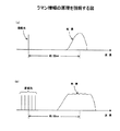
ラマン増幅では、光ファイバに励起光を与えることによりその励起光の波長よりも長波長側に利得が得られる。例えば、GeO2 ドープのシリカ(SiO2 )系光ファイバの場合、1.55μm帯においては、図30(a) に示すように、励起光の波長よりも約100nm長波長側に利得が得られる。なお、このシフト量は、周波数に換算すると、13.2テラHzである。また、ラマン増幅器は、励起光さえ用意できれば任意の波長を増幅できる。
【0008】
ラマン増幅器は、上記性質を利用することにより実現される。そして、広い利得波長帯域を得るためには、図30(b) に示すように、中心周波数が互いに異なる複数の励起光が使用される。なお、この方法は、例えば、Y. Emori, et al., "100nm bandwidth flat gain Raman amplifiers pumped and gain-equalized by 12-wavelength channel WDM high power laser diodes", OFC'99 PD19 1999.に記載されている。このように、複数の励起光を使用することにより、広い利得波長帯域が確保され得る。
【0009】
図31は、ラマン増幅を利用した波長多重光伝送システムの構成図である。ラマン増幅のための励起光は、基本的に、信号光とは逆方向に伝送されるように伝送路光ファイバに与えられる。このとき、図30(b) に示すように複数の励起光を使用する場合には、互いに発振周波数の異なる複数の光源から出力される励起光が波長合成器等により伝送路光ファイバに与えられる。
【0010】
【発明が解決しようとする課題】
上述のように、ラマン散乱を利用するラマン増幅器では、1.55μm帯においては、励起光の波長よりも約100nm程度波長の長い帯域の利得が得られる。たとえば、図32において、波長λ1 の励起光P1 が与えられると、波長λ1 よりも約100nmの長い波長帯域(波長λ3 の近傍領域)で利得が得られる。同様に、波長λ2 の励起光Pk が与えられると、波長λ2 よりも約100nm波長の長い帯域(波長λ4 の近傍領域)で利得が得らる。従って、複数の励起光P1 〜Pk が適切に使用されれば、約100nm程度の利得波長帯域幅が得られることになる。そして、この場合、信号光S1 〜SL は、この100nm程度の利得波長帯域を利用して伝送される。
【0011】
しかし、従来のラマン増幅器においては、利得波長帯域幅は、励起光の波長とその励起光に起因して得られるラマン利得の波長とのシフト量により制限されていた。すなわち、励起光の波長とその励起光に起因して得られるラマン利得の波長との差が100nmである場合には、ラマン増幅器によって得られる最大利得波長帯域幅も約100nm程度であった。
【0012】
本発明の課題は、より広い利得波長帯域幅が得られるラマン増幅器を提供することである。
【0013】
【課題を解決するための手段】
本発明のラマン増幅器は、複数の信号光が波長多重により多重化された波長多重信号光を増幅する構成であって、上記波長多重信号光およびその波長多重信号光を増幅するための第1の励起光を伝搬する伝送路と、上記波長多重信号光を増幅するための第2の励起光を生成する光源と、上記光源により生成される第2の励起光を上記伝送路に供給する光学手段とを有し、上記第1の励起光または第2の励起光の少なくとも一方が上記波長多重信号光の帯域内に配置されるラマン増幅器。
【0014】
上記構成において、たとえば、第1の励起光が波長多重信号光の帯域内に適切に配置され、第2の励起光が波長多重信号光よりも短波長側に適切に配置されると、その第2の励起光によって信号光の一部および第1の励起光が増幅されると共に、その増幅された第1の励起光によって他の信号光が増幅される。ラマンシフト量よりも広い帯域においてラマン増幅が実現される。
【0015】
本発明の他の形態のラマン増幅器は、複数の信号光が波長多重により多重化された波長多重信号光を増幅する構成であって、上記波長多重信号光およびその波長多重信号光の波長よりも長い波長を持った補助光を伝搬する伝送路と、上記波長多重信号光を増幅するための励起光を生成する光源と、上記光源により生成される励起光を上記伝送路に供給する光学手段とを有する。
【0016】
上記構成において、波長多重信号光は、励起光によって増幅される。また、補助光は、増幅された波長多重信号光のエネルギーの一部を吸収する。よって、波長多重信号光の光パワーが必要以上に大きくなることが回避される。
【0017】
本発明の光伝送システムは、複数の信号光が波長多重により多重化された波長多重信号光がラマン増幅器により増幅される構成であって、上記ラマン増幅器がラマンシフト量のn分の1の周波数間隔で配置される複数の励起光を用いて上記波長多重信号光を増幅する(nは整数)。
【0018】
上記構成において、ラマン増幅のための励起光は、ラマンシフト量のn分の1の周波数間隔で配置されているので、ある励起光によるラマン利得のピーク周波数が他の励起光の周波数と一致する。したがって、ラマン利得を等化するための各励起光パワーの調整が容易になる。
【0019】
【発明の実施の形態】
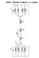
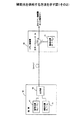
図1は、本発明のラマン増幅器が設けられる光伝送システムの構成図である。この伝送システムは、端局10および端局20を備え、それらの間は多心光ファイバケーブルにより接続されている。そして、端局10と端局20との間で双方向に信号が伝送される。
【0020】
端局10は、複数の光送信機11および複数の光受信機12を備える。一方、端局20は、複数の光受信機21および複数の光送信機22を備える。そして、各光送信機11から送出される信号は、光ファイバを介して伝送され、対応する光受信機21により受信される。一方、各光送信機22から送出される信号は、光ファイバを介して伝送され、対応する光受信機12により受信される。なお、各送信機11、22は、それぞれ波長多重光を送出する。すなわち、この伝送システムでは、多心光ファイバケーブルを構成する各光ファイバを介して、それぞれ波長多重光が伝送される。
【0021】
端局10と端局20との間の伝送路には、複数のラマン増幅器30−1〜30−nが設けられている。各ラマン増幅器30−1〜30−nは、それぞれ多心光ファイバケーブルを構成する各光ファイバを介して伝送される波長多重光を増幅する。なお、ラマン増幅では、光ファイバに励起光を与えることによりその光ファイバ自体が光増幅器として働く。したがって、「ラマン増幅器」は、光ファイバおよびその光ファイバに励起光を供給する装置から構成されるが、光ファイバに励起光を供給する装置のことを「ラマン増幅器」を呼ぶこともある。また、各ラマン増幅器は、それぞれ光中継装置の中に設けられてもよい。
【0022】
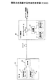
図2は、ラマン増幅器30の構成図である。なお、ラマン増幅器30−1〜30−nは、基本的に互いに同じ構成である。そして、「ラマン増幅器30」は、ラマン増幅器30−1〜30−nの中の任意の1つを表す。
【0023】
ラマン増幅器30は、複数の励起光源31、合波器32および合波器33を備える。複数の励起光源31は、互いに異なる波長の励起光を生成する。この実施例では、4個の励起光源により、波長λ1 〜λ4 の励起光が生成される。なお、各励起光源31は、たとえば、レーザダイオードである。レーザダイオードは、一般に、与えられた電流に対応するパワーの光を出力する。また、多くのレーザダイオードは、発光パワーを検出するためのバックパワーモニタ機能を備えている。以下では、各励起光源31の発光パワーは、バックパワーモニタ機能または他の方法により検出可能であるものとする。
【0024】
合波器32は、複数の励起光源31から出力される励起光を合波する。この実施例では、合波器32により波長λ1 〜λ4 の励起光が合波される。また、合波器32は、複数の出力ポートを備え、合波した励起光を各出力ポートからそれぞれ出力する。なお、合波器32は、例えば、波長多重カプラにより実現することができる。また、合波器33は、多心光ファイバケーブルに収容される各光ファイバ毎に設けられ、合波器32から出力される励起光を対応する光ファイバに供給する。このとき、励起光は、基本的に、信号光とは逆方向に伝送されるように光ファイバに入射される。
【0025】
上記構成により、互いに波長の異なる複数の励起光が合波され、その合波励起光が複数の光ファイバにそれぞれ供給される。なお、図2に示す例では、ラマン増幅器30に4個の励起光源31が設けられているが、本発明はこれに限定されるものではない。励起光源31の数は、例えば、必要な利得波長帯域幅に基づいて決定されてもよい。また、この例では、励起光源31の数と光ファイバの数とが互いに一致しているが、本発明はこれに限定されるものではなく、これらの数が互いに異なっていてもよい。
【0026】
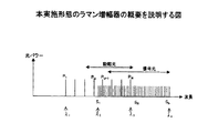
図3は、本実施形態のラマン増幅器の概要を説明する図である。なお、本実施形態のラマン増幅器30は、複数の光ファイバを介して伝送される波長多重光をそれぞれ増幅するが、各光ファイバについての増幅動作は、基本的に互いに同じである。したがって、以下では、多心光ファイバケーブルに収容されている複数の光ファイバの中の任意の光ファイバについての動作を説明する。
【0027】
ラマン増幅器30が設けられる光伝送システムでは、複数の信号が波長多重により多重化されて伝送される。すなわち、複数の信号は、互いに波長の異なる搬送波を利用して伝送される。この例では、これらの信号は、波長λ2 〜λ4 の搬送波を利用して伝送されるものとする。なお、以下では、信号を伝送するための搬送波のことを「信号光」と呼ぶことにする。具体的には、この光伝送システムでは、波長λ2 〜λ4 の信号光S1 〜Sn が波長多重により多重化されて伝送される。
【0028】
ラマン増幅器30は、複数の励起光P1 〜Pm を使用する。ここで、これらの励起光は、図2を参照しながら説明したように、それぞれ対応する励起光源31により生成され、合波器32により合波されて光ファイバに供給される。
【0029】
励起光P1 〜Pm は、図3に示すように、波長帯域λ1 〜λ3 の中に配置される。すなわち、励起光として使用される波長帯および信号光として使用される波長帯は、互いにその一部が重複している。具体的には、波長帯λ2 〜λ3 において、励起光PQ+1 〜Pm および信号光S1 〜Sr が混在している。
【0030】
このように、本実施形態のラマン増幅器が使用される光伝送システムでは、励起光として使用される波長帯域の一部および信号光として使用される波長帯域の一部が互いに重複している。
【0031】
なお、ラマン増幅においては、上述したように、与えられた励起光の波長に対応する波長帯域において利得が得られる。ここで、励起光の波長とその励起光に対応して利得が得られる波長との差(以下、ラマンシフト量)は、1.55μm帯において約100nmである。たとえば、励起光の波長が1.45μmであれば、その励起光に起因して発生する利得のピークの波長は約1.55μmとなる。また、励起光の波長が1.45+Δμmであれば、その励起光に起因して発生する利得のピークの波長は約1.55+Δμmとなる。すなわち、ラマン増幅において得られる利得の波長帯域は、励起光の波長帯域から約100nmシフトしている。このため、図3において、信号光S1 〜Sn を伝送するための波長帯域λ2 〜λ4 は、励起光P1 〜Pm として使用される波長帯域λ1 〜λ3 に対して100nmだけシフトしている。
【0032】
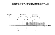
図4は、本実施形態のラマン増幅器の動作を説明する図である。ラマン増幅器30により励起光P1 〜PQ が与えられると、波長帯域λ2 〜λ3 において利得が得られる。これにより、信号光S1 〜Sr は、励起光P1 〜PQ に起因するラマン増幅により増幅される。ここで、波長λ1 と波長λ2 との差が100nmであるものとすると、利得波長帯域幅λ2 〜λ3 も約100nmとなる。
【0033】
同様に、ラマン増幅器30により励起光PQ+1 〜Pm が与えられると、波長帯域λ3 〜λ4 において利得が得られる。これにより、信号光Sr 〜Sn は、励起光PQ+1 〜Pm に起因するラマン増幅により増幅される。ここで、励起光PQ+1 〜Pm が設定される波長帯域λ2 〜λ3 が100nmなので、利得帯域幅λ3 〜λ4 も約100nmとなる。この結果、全利得帯域幅λ2 〜λ4 は、約200nmとなる。すなわち、ラマン増幅器において、ラマンシフト量よりも大きな利得波長帯域幅が得られる。
【0034】
ただし、本実施形態のシステムでは、波長帯域λ2 〜λ3 において信号光および励起光が混在している。このため、この波長帯域では、励起光P1 〜PQ により、信号光だけでなく励起光も増幅される。具体的には、励起光P1 〜PQ により、信号光S1 〜Sr および励起光PQ+1 〜Pm が増幅される。この結果、波長帯域λ3 〜λ4 の利得は、励起光PQ+1 〜Pm のみに依存するのではなく、励起光PQ+1 〜Pm を増幅する励起光P1 〜PQ にも依存する。また、ラマン増幅作用は、励起光のような連続波(CW:Continuous Wave )のみにより生じるものではなく、信号光のような不連続光によっても生じる。このため、波長帯域λ2 〜λ3 の信号光S1 〜Sr は、波長帯域λ3 〜λ4 において利得を発生させる。すなわち、波長帯域λ3 〜λ4 の利得は、信号光S1 〜Sr にも依存する。
【0035】
このように、励起光として使用される波長帯域と信号光として使用される波長帯域とが互いに重複すると、利得の調整が複雑になる。なお、利得の調整方法については、後で説明する。
【0036】
図5は、より広い利得波長帯域幅を得るためのラマン増幅の概念を説明する図である。この例では、励起光P1 〜Pm は、波長帯域λ1 〜λ5 において適切に設定されている。この場合、この励起光P1 〜Pm により、波長帯域λ2 〜λ6 において利得が得られる。ここで、波長帯域λ2 〜λ6 は、波長帯域λ1 〜λ5 から約100nmシフトしている。また、波長λ1 と波長λ5 との差を300nmとすると、励起光P1 〜Pm によって約300nmの利得が得られることになる。
【0037】
上記構成においては、励起光P1 〜Pm によって波長帯域λ2 〜λ6 において利得が得られるので、信号光S1 〜Sn は、この波長帯域λ2 〜λ6 に設定されている。従って、波長帯λ2 〜λ5 においては、励起光と信号光とが混在する。具体的には、この波長帯域においては、励起光PQ+1 〜Pm および信号光S1 〜Sr が混在している。
【0038】
図6は、図5に示すラマン増幅器の動作を説明する図である。このラマン増幅器では、3段階のラマン励起が生じる。すなわち、波長帯域λ1 〜λ2 に設定されている励起光P1 〜PQ により波長帯域λ2 〜λ3 において利得が得られる。また、波長帯域λ2 〜λ3 に設定されている励起光PQ+1 〜Pk により波長帯域λ3 〜λ5 において利得が得られる。さらに、波長帯域λ3 〜λ5 に設定されている励起光Pk+1 〜Pm により波長帯域λ5 〜λ6 において利得が得られる。ここで、波長帯域λ1 〜λ2 、波長帯域λ2 〜λ3 、波長帯域λ3 〜λ5 をそれぞれ100nmとすると、全利得帯域幅λ2 〜λ6 は、約300nmとなる。すなわち、このラマン増幅器によれば、ラマンシフト量の3倍の利得波長帯域幅が得られる。
【0039】
なお、図3〜図6に示す例では、ラマンシフト量の2倍または3倍の利得波長帯域幅を得ているが、本発明はこれに限定されるものではない。すなわち、より広い波長帯域に渡って複数の励起光を適切に設定すれば、より広い利得波長帯域幅が得られる。例えば、ラマンシフト量の4倍の波長帯域に渡って複数の励起光を適切に設定することにより、4段階のラマン励起が起こるようにすれば、ラマンシフト量の4倍の利得波長帯域幅(すなわち、400nm)が得られる。
【0040】
図7は、信号光および励起光の配置方法を説明する図である。本実施形態のシステムは、波長多重伝送を前提としているが、この波長多重伝送において使用すべき搬送波の波長(周波数)はITU−T(International Telecommunication Union Telecommunication standardization sector)において規定されている。そして、ITU−Tにおいて規定されている仕様は、しばしばITU−Tグリッドと呼ばれている。
【0041】
ITU−Tグリッドの基準周波数は、193.1THz である。そして、搬送波としては、図7(a) に示すように、この基準周波数およびその基準周波数を25GHZ ずつシフトさせることによって得られる周波数が使用される。なお、この帯域において、25GHz は、約0.2nmに相当する。
【0042】
複数の信号光は、基本的に、ITU−Tグリッドに従って設定される。具体的には、複数の信号光は、25GHz 毎(約0.2nm毎)に設定される。また、複数の励起光も、ITU−Tグリッドに従って設定される。即ち、各励起光の周波数は、基本的に、193.1±0.025×n(THz )である。ここで、「n」は整数である。ただし、励起光は、信号光が設定される間隔よりも大きな間隔で設定される。
【0043】
このように、本実施形態では、信号光および励起光は、共にITU−Tグリッドに従って設定される。このとき、信号光は、基本的には25GHz 毎に設定されるが、励起光が設定されるべき波長には設定されない。即ち、信号光および励起光に対して同じ波長が割り当てられることはない。また、励起光のパワーは、通常、信号光のパワーよりも大きいので、励起光のスペクトラムは、図7(b) に示すように、信号光のそれと比較して広くなる。このため、ある波長を励起光に割り当てる場合には、その波長に近接する数個の波長は、信号光に対して割り当てられない。
【0044】
複数の励起光は、基本的には、図8に示すように、等間隔に配置される。尚、複数の励起光が等間隔に配置されると、それらの励起光のパワーの制御によってラマン利得を調整することが比較的容易になる。
【0045】
次に、伝送路に励起光を供給するための幾つかの構成および方法について説明する。なお、以下では、励起光P1 〜Pm により信号光S1 〜Sn が増幅されるものとする。
【0046】
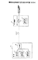
図9は、伝送路に励起光を供給する方法の一例を示す図である。この方法においては、励起光P1 〜PQ が各ラマン増幅器30により供給され、励起光PQ+1 〜Pm が端局10により供給される。
【0047】
端局10は、信号光S1 〜Sn を生成するための信号光源41、励起光PQ+1 〜Pm を生成するための励起光原42、およびこれらの信号光および励起光を合波する合波器43を備える。これにより、信号光および励起光が波長多重により多重化されて伝送路光ファイバに送出される。なお、信号光S1 〜Sn 及び励起光PQ+1 〜Pm の波長は、図3〜図5に示す波長λ2 よりも長いものとする。
【0048】
各ラマン増幅器30は、励起光P1 〜PQ を生成するための励起光源31およびそれらの励起光を伝送路に導くための合波器33を備える。ここで、励起光源31は、例えば、これらの励起光を生成するための複数のレーザダイオードLDである。また、これらの励起光は、合波器(図2の合波器32)により合波され合波器33に与えられる。なお、励起光P1 〜PQ の波長は、図3〜図5に示す波長λ2 よりも短いものとする。
【0049】
合波器33は、3つの入出力ポート(a〜cポート)を備える。aポートは端局10側の光ファイバに接続され、bポートは端局20側の光ファイバに接続され、cポートは励起光源31により生成される励起光を受信する。そして、合波器33は、波長λ2 よりも長い波長を持った光をaポートから受信したときに、それをbポートを介して出力する。すなわち、合波器33は、端局10側の光ファイバを介して信号光S1 〜Sn および励起光PQ+1 〜Pm を受信すると、それらを端局20側の光ファイバを介して出力する。また、合波器33は、波長λ2 よりも短い波長を持った光をcポートから受信したときに、それをaポートを介して出力する。すなわち、合波器33は、cポートを介して受信する励起光P1 〜PQ を端局10側の光ファイバへ導く。
【0050】
続いて、図4を参照しながら上記構成のラマン増幅器の動作を説明する。上記構成において、励起光源31により生成される励起光P1 〜PQ は、伝送路光ファイバに供給される。この結果、波長帯域λ2 〜λ3 において利得が得られる。すなわち、励起光P1 〜PQ により、波長帯域λ2 〜λ3 に配置されている光が増幅されることになる。具体的には、波長帯域λ2 〜λ3 に配置されている信号光S1 〜Sr および励起光PQ+1 〜Pm が増幅される。また、この増幅された励起光PQ+1 〜Pm により、波長帯域λ3 〜λ4 において利得が得られる。即ち、励起光PQ+1 〜Pm により、波長帯域λ3 〜λ4 に配置されている信号光Sr+1 〜Sn が増幅される。このようにして、各ラマン増幅器30により信号光S1 〜Sn が増幅される。
【0051】
図10は、伝送路に励起光を供給する方法の他の例を示す図である。この方法においては、励起光P1 〜Pm が各ラマン増幅器30により供給される。
端局10は、信号光S1 〜Sn を生成するための信号光源41を備える。そして、これらの信号光S1 〜Sn は、波長多重により多重化されて伝送路光ファイバに送出される。
【0052】
各ラマン増幅器30は、励起光P1 〜Pm を生成するための励起光源31およびそれらの励起光を伝送路に導く光サーキュレータ34を備える。ここで、励起光源31は、例えば、これらの励起光を生成するための複数のレーザダイオードLDである。また、これらの励起光は、不図示の合波器(図2の合波器32)により合波され光サーキュレータ34に与えられる。
【0053】
光サーキュレータ34は、3つの入出力ポート(a〜cポート)を備える。ここで、aポートから入力された光はbポートへ導かれ、bポートから入力された光はcポートへ導かれ、cポートから入力された光はaポートへ導かれる。したがって、光サーキュレータ34は、端局10側の光ファイバを介して入力される信号光S1 〜Sn を端局20側の光ファイバへ導く。また、光サーキュレータ34は、励起光源31により生成される励起光P1 〜Pm を端局10側の光ファイバへ導く。
【0054】
続いて、図4を参照しながら上記構成のラマン増幅器の動作を説明する。上記構成において、励起光源31により生成される励起光P1 〜Pm は、伝送路光ファイバに供給される。この結果、波長帯域λ2 〜λ4 において利得が得られる。すなわち、励起光P1 〜Pm により、波長帯域λ2 〜λ4 に配置されている信号光S1 〜Sn が増幅される。
【0055】
図11は、図10に示した方法の変形例である。この方法においては、励起光P1 〜Pm が各ラマン増幅器30により供給されると共に、端局10は、信号光が配置される波長帯域内の励起光(励起光PQ+1 〜Pm )を供給する。なお、この構成の動作は、図10を参照しながら説明した動作と基本的に同じなので、省略する。
【0056】
なお、図9〜図11に示すシステムにおいて、各励起光の光スペクトル幅は、基本的に、狭い方が望ましい。少なくとも、信号光が配置される帯域内に配置される励起光(例えば、励起光PQ+1 〜Pm )のスペクトル幅は、信号光のそれと同じ程度であることが望ましい。各励起光の光スペクトル幅は、例えば、光ファイバグレーティングによって調整される。
【0057】
ところで、波長多重伝送システムにおいては、一般に、波長多重光に含まれる各信号光のレベルが等化されていることが望ましい。そして、波長多重光に含まれる各信号光のレベルを等化するためには、各増幅器の利得を調整する必要がある。以下、各ラマン増幅器の利得を調整する方法を説明する。
【0058】
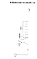
図12は、各ラマン増幅器30において利得を調整する機能を説明する図である。ラマン増幅器30は、複数の励起光源51を備える。これらの励起光源51は、互いに発振周波数の異なるレーザダイオードであり、それぞれ対応する駆動回路52により駆動される。また、駆動回路52は、制御部54からの指示に従って対応する励起光源51に電流を供給する。さらに、検出回路53は、それぞれ、信号光が伝送される波長帯域内の対応する波長の利得を検出する。なお、波長ごとに利得を検出する方法は、既知の技術を利用する。
【0059】
制御部54は、端局10または20からの問合せに従って、波長ごとに利得を調べる。この時、各検出回路53の出力が参照される。そして、制御部54は、その検出結果を端局10または20に通知する。また、制御部54は、端局10または20からの指示に従って駆動回路62を制御する。これにより、端局10または20からの指示に基づいて、特定の励起光源51の発光パワーが調整される。
【0060】
端局10または20は、各ラマン増幅器の利得を調整するための制御回路を備える。この制御回路は、この光伝送システムの構築時に、またはその後定期的に各ラマン増幅器の利得を調整する。具体的には、この制御回路は、まず、各ラマン増幅器に対して波長ごとの利得を問い合わせる。そして、その問合せに対する応答に従って、各ラマン増幅器における利得の波長特性が等化されるように指示を与える。例えば、あるラマン増幅器においてある波長の利得が相対的に低かった場合には、そのラマン増幅器に対して、その波長よりも約100nm短い波長の励起光のパワーを増加させる旨の指示が送出される。この場合、指示を受け取ったラマン増幅器は、その指示に従って対応する励起光のパワーを調整する。これにより、各ラマン増幅器における利得が等化される。
【0061】
なお、図9に示す構成のように、励起光の一部(励起光PQ+1 〜Pm )が端局10により生成される場合には、各ラマン増幅器により生成される励起光を調整するだけでなく、端局10により生成される励起光も調整する必要がある。この場合、端局10が各ラマン増幅器の利得を管理するのであれば、端局10自身が励起光PQ+1 〜Pm を調整してもよい。また、端局20が各ラマン増幅器の利得を管理するのであれば、端局20から端局10への通知に基づいて励起光PQ+1 〜Pm が調整されるようにしてもよい。
【0062】
このように、本実施形態のシステムでは、励起光P1 〜Pm の各光パワーを適切に調整することにより、各ラマン増幅器における利得の波長偏差を小さくしている。
【0063】
図13は、信号光S1 〜Sn の光S/N比を調整する方法を説明するための図である。信号光S1 〜Sn の光S/N比は、基本的に、信号光源41により生成される信号光S1 〜Sn の光パワーを調整することによって制御される。このため、本実施形態のシステムでは、受信側の端局(端局20)において波長ごとに光S/N比が検出され、その検出結果が送信側の端局(端局10)にフィードバックされる。
【0064】
端局20には、信号光S1 〜Sn を含む波長多重光を分岐するための分岐カプラ61、分岐カプラ61により分岐された波長多重光から信号光S1 〜Sn を取り出す分波器62、および分波器62により取り出された信号光S1 〜Sn のそれぞれについて光S/N比を検出するS/N検出回路63が設けられる。また、制御回路64は、各S/N検出回路63の出力に基づいて信号光S1 〜Sn の光S/N比の偏差を調べ、その偏差を小さくするための指示を作成する。具体的には、例えば、ある波長の信号光の光S/N比が相対的に劣悪であったとすると、その波長の信号光のパワーを大きくする旨の指示を作成する。そして、作成された指示は、端局10に送られる。
【0065】
端局10は、端局20から指示を受け取ると、それに従って信号光源41のパワーを調整する。これにより、信号光S1 〜Sn の光S/N比の偏差が小さくなる。
【0066】
このように、本実施形態の光伝送システムでは、ラマン増幅による利得および信号光の光S/N比が個別に調整される。すなわち、波長に依存するラマン利得の偏差を小さくするために各励起光の光パワーが適切に調整され(励起光プリエンファシス)、また、複数の信号光の光S/N比の偏差を小さくするために各信号光の光パワーが適切に調整される(信号光プリエンファシス)。
【0067】
なお、上述したように、本実施形態のラマン増幅器では、信号光の一部(例えば、図3のS1 〜Sr )が、それよりも長波長側の信号光に対して励起光として働く。しかし、各信号光の光パワーは、励起光のそれと比較して十分に小さいので、信号光により生じる利得は、励起光により生じる利得と比べて小さい。したがって、ラマン増幅器の利得は、各励起光の光パワーを制御することによって概ね所望の特性に調整される。このとき、必要に応じて信号光の光パワーが微調整されてもよい。また、S/N検出回路の代わりに、各波長毎の光受信機が持つ符号誤り率を用いることも可能である。
【0068】
次に、ラマン増幅の特性を利用して光伝送システムの伝送性能を向上させる方法を説明する。
図14は、混合伝送路ファイバが設けられた光伝送システムの構成図である。このシステムでは、波長多重光を伝送するための光ファイバとして、混合伝送路ファイバが使用されている。この混合伝送路ファイバは、第1の光ファイバおよびその第1の光ファイバと比較してモードフィールド径(実効断面積、或いはコア径)の小さい第2の光ファイバから構成される。ここで、一実施例としては、第1の光ファイバが正分散を持ち、第2の光ファイバが負分散を持つことが望ましい。そして、信号光は、光送信機11から光受信機21へ伝送される際、各混合伝送路上では、先に第1の光ファイバを介して伝搬され、その後に第2の光ファイバを介して伝搬されるようになっている。
【0069】
図15は、図14に示すシステムにおけるラマン増幅器の構成図である。ここでは、伝送路上に設けられる複数のラマン増幅器のなかの任意の1つを示している。
【0070】
ラマン増幅器30は、信号光とは逆方向に励起光が伝送されるように伝送路に励起光を供給する。すなわち、励起光は、後方励起方式により伝送路に供給される。このため、励起光源31により生成される励起光は、まず、第2の光ファイバに供給され、その第2の光ファイバを通過した後に第1の光ファイバに供給されることになる。ここで、ラマン増幅は、よく知られているように、光ファイバに供給される励起光のパワー密度が高いほど効率的に利得が得られる。即ち、ラマン増幅は、光ファイバのモードフィールド径が小さいほど効率的に利得が得られる。したがって、本実施形態の構成においては、第2の光ファイバにおいて効率的に利得が得られる。この結果、信号光の光S/N比が向上する。
【0071】
また、このシステムでは、光伝送路上の非線形効果も抑えられる。ここで、光伝送路上の非線形効果は、よく知られているように、光ファイバのモードフィールド径が小さいほど大きく、また、信号光の光パワーが大きいほど大きくなる。しかし、このシステムにおいては、信号光の光パワーが大きい状態のときは、モードフィールド径が比較的大きい第1の光ファイバを伝搬されるので、非線形効果は小さい。また、信号光は、モードフィールド径の小さい第2の光ファイバに到達したときには十分に減衰しているので、第2の光ファイバにおいて発生する非線形効果も小さい。すなわち、全伝送路において非線形効果が抑制され、伝送波形の歪みが小さくなる。
【0072】
このように、第1および第2の光ファイバから構成される混合伝送路を使用すると、信号光の光S/N比が向上すると共に、非線形効果による信号波形の歪みが抑えられる。なお、第1の光ファイバの長さと第2の光ファイバの長さの比率は、例えば、2:1である。また、第1および第2の光ファイバの実効面積は、例えば、それぞれ、110マイクロ平方メートル、20マイクロ平方メートル程度である。
【0073】
なお、図14および図15に示す例では、混合伝送路ファイバは、モードフィールド径の異なる2種類の光ファイバから構成されているが、本発明はこれに限定されるものではない。すなわち、混合伝送路ファイバは、3種類以上の光ファイバから構成されてもよい。例えば、図16および図17に示す例では、各混合伝送路ファイバは、それぞれ第1〜第3の光ファイバにより構成されている。この場合、第1の光ファイバのモードフィールド径が最も大きく、第3の光ファイバのモードフィールド径が最も小さくなっている。このように、混合伝送路ファイバは、複数種類の光ファイバが、信号光が伝送される方向において、そのモードフィールド径が徐々に小さくなっていくように接続されることによって構成されればよい。
【0074】
ところで、ラマン増幅では、図3〜図6を参照しながら説明したように、光ファイバに励起光を供給すると、その励起光の波長からラマンシフト量だけ長波長側にシフトした波長帯域において利得が得られる。このとき、この利得波長帯域に光が存在すれば、その光は増幅される。たとえば、図4において、光ファイバに励起光P1 〜PQ を供給すると、波長帯域λ2 〜λ3 に配置されている光(信号光および励起光を含む)が増幅される。このとき、波長帯域λ2 〜λ3 に配置されている光は、励起光P1 〜PQ として与えられたエネルギーの一部を吸収することによって増幅される。
【0075】
このように、ラマン増幅は、励起光として与えられたエネルギーが、その励起光の波長よりも長波長側に配置されている光に吸収されることによって生じる。このとき、励起光の光パワーは、そのエネルギーの一部が他の光によって吸収されたときに、その分だけ低下することになる。反対に、励起光の光パワーは、そのエネルギーの一部が他の光によって吸収されなければ、ほとんど低下することはない。すなわち、励起光の光パワーは、そのエネルギーの一部が他の光によって吸収されるか否かによって変動する可能性がある。
【0076】
そして、この問題は、励起光に限ったことではない。例えば、図4において、波長帯域λ1 〜λ2 に配置されている光のエネルギーは波長帯域λ2 〜λ3 に配置されている光により吸収され、波長帯域λ2 〜λ3 に配置されている光のエネルギーは波長帯域λ3 〜λ4 に配置されている光により吸収される。ところが、波長帯域λ3 〜λ4 に配置されている光のエネルギーは、他の光によって吸収されることはない。この結果、波長帯域λ3 〜λ4 における利得が必要以上に大きくなってしまう可能性がある。あるいは、波長帯域λ3 〜λ4 に配置されている信号光のレベルが必要以上に高くなってしまう可能性がある。
【0077】
本実施形態のシステムでは、上述の問題を解決するために、図18に示すように、信号光S1 〜Sn が配置される波長帯域よりも長波長側に補助光A1 〜At が配置される。これにより、波長帯域λ3 〜λ4 に配置されている信号光Sr 〜Sn のエネルギーは、補助光A1 〜At により吸収される。すなわち、波長帯域λ3 〜λ4 における利得が適切に抑制される。
【0078】
なお、補助光A1 〜At は、3段以上のラマン増幅が行われるシステムにおいても使用可能である。3段のラマン増幅が行われるシステムにおいて補助光A1 〜At が配置される場合に例を図19に示す。
【0079】
補助光A1 〜At は、端局10により生成されてもよいし、各ラマン増幅器30により生成されてもよい。補助光A1 〜At を生成するための補助光源が設けられたシステムの構成例を図20〜図23に示す。図20および図22に示す例では、補助光A1 〜At を生成するための補助光源71は、各ラマン増幅器30に設けられる。この場合、補助光A1 〜At は、励起光P1 〜Pm と共に伝送路光ファイバに供給される。一方、図21および図23に示す例では、補助光A1 〜At を生成するための補助光源71は、端局10に設けられる。この場合、補助光A1 〜At は、信号光S1 〜Sn と共に波長多重により多重化されて伝送路を伝搬される。
【0080】
補助光A1 〜At は、信号光または励起光と同様に、図7(a) に示すITU−Tグリッドに従って配置されるようにしてもよい。また、補助光A1 〜At は、励起光と同様に、一定の周波数間隔で配置されるようにしてもよい。
【0081】
さらに、補助光A1 〜At は、端局10または20が各ラマン増幅器または伝送路の状態を調べるための監視信号を伝送する搬送波として利用されてもよい。ただし、この場合は、補助光A1 〜At は、基本的に、端局によって生成される必要がある。なお、上記監視信号は、励起光P1 〜Pm を利用して伝送されるようにしてもよい。
【0082】
さらに、補助光A1 〜At の光パワーは、端局10または20からの指示によって調整されるようにしてもよい。この場合、補助光A1 〜At の光パワーは、信号光が配置されている波長帯域の利得が等化されるように調整される。具体的には、例えば、信号光が配置されている波長帯域の中の長波長領域の利得が相対的に高くなっているか否かに基づいて、補助光A1 〜At の光パワーが調整される。
【0083】
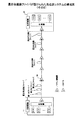
図24は、本発明の光伝送システムの構成図である。このシステムでは、伝送路上に複数のラマン増幅器30が設けられていると共に、端局には希土類ドープファイバを利用した増幅器(以下、希土類ドープファイバ増幅器)が設けられている。また、このシステムでは、上述したラマン増幅器を使用することにより、100nm以上の波長帯域を利用して信号光が伝送されるものとする。なお、図24では描かれていないが、希土類ドープファイバ増幅器は端局10にも設けられる。
【0084】
希土類ドープファイバ増幅器の利得波長帯域は、よく知られているように、光ファイバ内に注入される物質によって異なる。しかし、希土類ドープファイバ増幅器の有効な利得波長帯域の幅は、通常、30〜40nm程度である。したがって、100nm以上の波長帯域を持った波長多重信号光を増幅するためには、互いに利得波長帯域の異なる複数の希土類ドープファイバ増幅器を用いる必要がある。図24に示す例では、互いに利得波長帯域の異なる希土類ドープファイバ増幅器81a〜81nが端局に設けられている。なお、波長多重信号光は、端局20において不図示の分波器により希土類ドープファイバ増幅器81a〜81nの利得波長帯域ごとに分波され、それぞれ対応する希土類ドープファイバ増幅器81a〜81nにおいて増幅される。以下では、ラマン増幅器と希土類ドープファイバ増幅器が混在する光伝送システムにおいて、ラマン増幅のための励起光を有効に配置する方法を説明する
本実施形態のシステムでは、複数の励起光は、下記(1) 式を満たすように配置される。ここで、「Δfr 」はラマンシフト量、「Δfe 」は励起光を配置すべき間隔、「n」は任意の整数である。
【0085】
Δfr =n・Δfe ・・・(1)
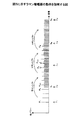
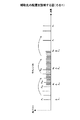
図25(a) は、上記(1) 式に「n=1〜6」が代入されたときの利得帯域幅を示す対応表である。尚、ラマンシフト量(Δfr )は13.2THz である。この場合、「n」として1〜6が与えられると、励起光を配置すべき間隔(Δfe )としてはそれぞれ13.2〜2.2THz が得られる。そして、これらの間隔は、1550nm付近において波長に換算すると、それぞれ105.7〜17.6nmとなる。ここで、希土類ドープファイバ増幅器の利得帯域幅は、それぞれ30〜40nmである。したがって、希土類ドープファイバ増幅器81a〜81nの個数を出来るだけ少なくするためには、上記(1) 式に与えるべき「n」としては「3」が好適である。
【0086】
図26は、上記(1) 式に基づいて励起光を配置する場合の実施例である。ここでは、上記(1) 式において「n=3」が与えられた場合を示している。即ち、励起光P1 〜P10は、4.4THz 毎に配置される。
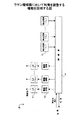
【0087】
信号光が配置される波長帯域は、この実施例では、1435〜1667nmである。そして、この信号光波長帯域は、伝送路上では、励起光P1 〜P10を使用することにより各ラマン増幅器30によって一括して増幅される。一方、端局内では、この信号光波長帯域は、複数の希土類ドープファイバ増幅器81a〜81nにより波長帯域ごとに増幅される。具体的には、この信号光波長帯域は、7つの波長帯域(S++帯域、S+ 帯域、S帯域、C帯域、L帯域、L+ 帯域、L++帯域)に分波され、それぞれ対応する希土類ドープファイバ増幅器81a〜81nによって増幅される。ここで、S++帯域〜L++帯域は、この実施例では、励起光P4 〜P10によって仕切られる波長帯域(または、周波数帯域)のことをいう。すなわち、S++帯域〜L++帯域の幅は、それぞれ4.4(30〜40nm程度)である。従って、希土類ドープファイバ増幅器81a〜81nは、それぞれ対応するS++帯域〜L++帯域を増幅することができる。具体的には、例えば、希土類ドープファイバ増幅器81aは、波長帯域1435〜1467nmを増幅し、希土類ドープファイバ増幅器81bは、波長帯域1467〜1500nmを増幅する。
【0088】
また、上記(1) 式によれば、各励起光によるラマン利得のピーク波長と対応する励起光の波長とが一致するように各励起光が配置される。例えば、励起光P1 に起因するラマン利得がピークになる波長は励起光P4 の波長に一致し、励起光P2 に起因するラマン利得がピークになる波長は励起光P5 の波長に一致する。従って、ラマン利得を等化するために各励起光の光パワーを調整する作業(プリエンファシス)が容易になることが期待される。
【0089】
本実施形態の他の形態のシステムでは、複数の励起光は、下記(2) 式を満たすように配置される。ここで、「Δfr 」はラマンシフト量、「Δfe 」は励起光を配置すべき間隔、「n」は任意の整数である。
【0090】
Δfr =(n+0.5)・Δfe ・・・(2)
図25(b) は、上記(2) 式に「n=1〜6」が代入されたときの利得帯域幅を示す対応表である。図25(b) に示すように、「n」として1〜6が与えられると、励起光を配置すべき間隔(Δfe )としてはそれぞれ8.8〜2.0THz が得られる。そして、これらの間隔は、1550nm付近において波長に換算すると、それぞれ70.5〜16.3nmとなる。ここで、希土類ドープファイバ増幅器の利得帯域幅が30〜40nmであることを考慮すると、上記(2) 式に与えるべき「n」としては、「2」または「3」が好適である。
【0091】
図27は、上記(2) に基づいて励起光を配置する場合の実施例である。ここでは、上記(2) 式において「n=3」が与えられた場合を示している。すなわち、励起光P1 〜P10は、3.77THz 毎に配置される。なお、この実施例においても、図26に示した方法と同様に、信号光波長帯域は複数の波長帯域(S++帯域〜L++帯域)に分波され、それぞれ対応する希土類ドープファイバ増幅器81a〜81nによって増幅される。
【0092】
上記(2) 式によれば、各励起光によるラマン利得のピーク波長は、その励起光から見てn個先の励起光の波長と(n+1)個先の励起光の波長のほぼ中間の波長となる。たとえば、励起光P1 に起因するラマン利得がピークになる波長は、励起光P4 の波長と励起光P5 の波長のほぼ中間の波長となる。ここで、この実施例では、励起光P4 〜P10によって仕切られる各波長帯域(S++帯域〜L++帯域)は、それぞれ対応する希土類ドープファイバ増幅器81a〜81nにより増幅される。したがって、各励起光によるラマン利得のピーク周波数は、対応する希土類ドープファイバ増幅器81a〜81nの利得波長帯域のほぼ中心になる。
したがって、安定した増幅動作が期待される。
【0093】
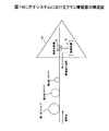
最後に、端局10または20が各ラマン増幅器または伝送路の状態を調べるための監視信号を伝送する監視制御光の配置方法を説明する。
監視制御光は、伝送システムを監視するための監視信号を伝送する搬送波である。そして、監視信号の伝送速度は、信号光によって伝送される信号と比べて十分に低速である。たとえば、信号光によって伝送される信号の伝送速度は、10Gbps程度であるのに対し、監視信号のそれは、数10kbps〜数Mbps程度である。このため、監視制御光は、信号光と比べて、その光S/N比が小さくても受信可能である。
【0094】
ところで、励起光の光パワーは、信号光のそれと比較して十分に大きい。このため、励起光の光スペクトル幅はかなり広く、その励起光の近傍では擾乱(クロストークや四光波混合など)が大きい。すなわち、励起光の近傍では、光S/N比が悪化することが予想される。このため、本実施形態のシステムでは、図28に示すように、励起光の近傍には、光S/N比について耐力がある監視制御光が配置される。これにより、励起光から離れた波長帯域が監視制御光により使用されることがなく、信号光を効率的に配置することが可能になる。
【0095】
(付記1)複数の信号光が波長多重により多重化された波長多重信号光を増幅するラマン増幅器であって、
上記波長多重信号光およびその波長多重信号光を増幅するための第1の励起光を伝搬する伝送路と、
上記波長多重信号光を増幅するための第2の励起光を生成する光源と、
上記光源により生成される第2の励起光を上記伝送路に供給する光学手段とを有し、
上記第1の励起光または第2の励起光の少なくとも一方が、上記波長多重信号光の帯域内に配置されるラマン増幅器。
(付記2)複数の信号光が波長多重により多重化された波長多重信号光を増幅するラマン増幅器であって、
上記波長多重信号光を伝搬する伝送路と、
上記波長多重信号光の帯域内に配置される第1の励起光および上記波長多重信号光の帯域外に配置される第2の励起光を生成する光源と、
上記光源により生成される第1の励起光および第2の励起光を上記伝送路に供給する光学手段と、
を有するラマン増幅器。
(付記3)付記1または付記2に記載のラマン増幅器であって、
上記第2の励起光の波長は、上記波長多重信号光の波長よりも短い。
(付記4)付記1または付記2に記載のラマン増幅器であって、
上記第1の励起光および第2の励起光は、それぞれ等しい周波数間隔で配置される。
(付記5)付記1または付記2に記載のラマン増幅器であって、
上記第1の励起光は、ITU−Tグリッドに従って配置される。
(付記6)付記1または付記2に記載のラマン増幅器であって、
上記第1の励起光および第2の励起光は、それぞれ2波以上の光から構成される。
(付記7)付記1または付記2に記載のラマン増幅器であって、
上記第1の励起光は、上記第2の励起光によって増幅される。
(付記8)複数の信号光が波長多重により多重化された波長多重信号光を増幅するラマン増幅器であって、
上記波長多重信号光および第1の励起光を伝搬する伝送路と、
上記波長多重信号光の帯域内に配置される第2の励起光および上記波長多重信号光の帯域外に配置される第3の励起光を生成する光源と、
上記光源により生成される第2の励起光および第3の励起光を上記伝送路に供給する光学手段と、
を有するラマン増幅器。
(付記9)第1の端局装置と第2の端局装置との間にラマン増幅器が設けられ、複数の信号光が波長多重により多重化された波長多重信号光が上記第1の端局装置から上記第2の端局装置へ伝送される光伝送システムであって、
上記第1の端局装置は、
上記波長多重信号光を生成する信号光源と、
第1の励起光を生成する第1の励起光源とを有し、
上記ラマン増幅器は、
上記波長多重信号光および第1の励起光を伝搬する伝送路と、
第2の励起光を生成する第2の励起光源と、
上記第2の励起光源により生成される第2の励起光を上記伝送路に供給する光学手段とを有し、
少なくとも上記第1の励起光の一部は、上記波長多重信号光の帯域内に配置され、
上記第1および第2の励起光の光パワーは、上記ラマン増幅器による利得が等化されるように調整される光伝送システム。
(付記10)第1の端局装置と第2の端局装置との間にラマン増幅器が設けられ、複数の信号光が波長多重により多重化された波長多重信号光が上記第1の端局装置から上記第2の端局装置へ伝送される光伝送システムであって、
上記第1の端局装置は、
上記波長多重信号光を生成する信号光源を有し、
上記ラマン増幅器は、
上記波長多重信号光を伝搬する伝送路と、
上記波長多重信号光の帯域内に配置される第1の励起光を生成する第1の励起光源と、
上記波長多重信号光の帯域外に配置される第2の励起光を生成する第2の励起光源と、
上記第1の励起光源により生成される第1の励起光および上記第2の励起光源により生成される第2の励起光を上記伝送路に供給する光学手段とを有し、
上記第1および第2の励起光の光パワーは、上記ラマン増幅器による利得が等化されるように調整される光伝送システム。
(付記11)付記9または付記10に記載の光伝送システムであって、
上記第1および第2の励起光の光パワーは、上記第1または第2の端局装置からの指示に従って調整される。
(付記12)付記9または付記10に記載の光伝送システムであって、
上記信号光のパワーは、上記第2の端局装置により検出される各信号光の光S/N比に基づいて調整される。
(付記13)複数の信号光が波長多重により多重化された波長多重信号光をラマン増幅器を用いて増幅する光増幅方法であって、
上記波長多重信号光が伝搬される伝送路に、その波長多重信号光の波長よりも短い波長の励起光およびその波長多重信号光が配置される帯域内の励起光を供給する光増幅方法。
(付記14)複数の信号光が波長多重により多重化された波長多重信号光を増幅するラマン増幅器であって、
上記波長多重信号光およびその波長多重信号光の波長よりも長い波長を持った補助光を伝搬する伝送路と、
上記波長多重信号光を増幅するための励起光を生成する光源と、
上記光源により生成される励起光を上記伝送路に供給する光学手段と、
を有するラマン増幅器。
(付記15)複数の信号光が波長多重により多重化された波長多重信号光を増幅するラマン増幅器であって、
上記波長多重信号光を伝搬する伝送路と、
上記波長多重信号光を増幅するための励起光およびその波長多重信号光の波長よりも長い波長を持った補助光を生成する光源と、
上記光源により生成される励起光および補助光を上記伝送路に供給する光学手段と、
を有するラマン増幅器。
(付記16)付記14または付記15に記載のラマン増幅器であって、
上記補助光は、それぞれ等しい周波数間隔で配置される。
(付記17)付記14または付記15に記載のラマン増幅器であって、
上記補助光は、ITU−Tグリッドに従って配置される。
(付記18)付記14または付記15に記載のラマン増幅器であって、
上記補助光は、2波以上の光から構成される。
(付記19)付記14または付記15に記載のラマン増幅器であって、
上記補助光は、上記複数の信号光の一部の信号光のエネルギーを吸収するように配置される。
(付記20)第1の端局装置と第2の端局装置との間にラマン増幅器が設けられ、複数の信号光が波長多重により多重化された波長多重信号光が上記第1の端局装置から上記第2の端局装置へ伝送される光伝送システムであって、
上記第1の端局装置は、
上記波長多重信号光を生成する信号光源と、
上記波長多重信号光の波長よりも長い波長を持った補助光を生成する補助光源とを有し、
上記ラマン増幅器は、
上記波長多重信号光および補助光を伝搬する伝送路と、
上記波長多重信号光を増幅するための励起光を生成する励起光源と、
上記励起光源により生成される励起光を上記伝送路に供給する光学手段とを有し、
上記補助光の光パワーは、上記ラマン増幅器による利得が等化されるように調整される光伝送システム。
(付記21)第1の端局装置と第2の端局装置との間にラマン増幅器が設けられ、複数の信号光が波長多重により多重化された波長多重信号光が上記第1の端局装置から上記第2の端局装置へ伝送される光伝送システムであって、
上記第1の端局装置は、
上記複数の信号光を生成する信号光源を有し、
上記ラマン増幅器は、
上記波長多重信号光を伝搬する伝送路と、
上記波長多重信号光を増幅するための励起光を生成する励起光源と、
上記波長多重信号光の波長よりも長い波長を持った補助光を生成する補助光源と、
上記励起光源により生成される励起光および上記補助光源により生成される補助光を上記伝送路に供給する光学手段とを有し、
上記補助光の光パワーは、上記ラマン増幅器による利得が等化されるように調整される光伝送システム。
(付記22)付記20または付記21に記載の光伝送システムであって、
上記補助光の光パワーは、上記第1または第2の端局装置からの指示に従って調整される。
(付記23)付記20または付記21に記載の光伝送システムであって、
当該伝送システムの状態を監視するための監視信号は、上記補助光により搬送される。
(付記24)複数の信号光が波長多重により多重化された波長多重信号光がラマン増幅器により増幅される光伝送システムであって、上記ラマン増幅器が、ラマンシフト量のn分の1の周波数間隔で配置される複数の励起光を用いて上記波長多重信号光を増幅する光伝送システム(nは整数)。
(付記25)複数の信号光が波長多重により多重化された波長多重信号光がラマン増幅器および希土類ドープファイバ増幅器により増幅される光伝送システムであって、
上記ラマン増幅器は、ラマンシフト量のn分の1の周波数間隔で配置される複数の励起光を用いて上記波長多重信号光を増幅し、
上記希土類ドープファイバ増幅器は、上記複数の励起光に対応する複数の増幅ユニットから構成され、各増幅ユニットがそれぞれ対応する波長帯域の信号光を増幅する光伝送システム(nは整数)。
(付記26)複数の信号光が波長多重により多重化された波長多重信号光がラマン増幅器および希土類ドープファイバ増幅器により増幅される光伝送システムであって、
上記ラマン増幅器は、ラマンシフト量の(n+0.5)分の1の周波数間隔で配置される複数の励起光を用いて上記波長多重信号光を増幅し、
上記希土類ドープファイバ増幅器は、上記複数の励起光に対応する複数の増幅ユニットから構成され、各増幅ユニットがそれぞれ対応する波長帯域の信号光を増幅する光伝送システム(nは整数)。
(付記27)複数の信号光が波長多重により多重化された波長多重信号光がラマン増幅器により増幅される光伝送システムであって、
上記ラマン増幅器は、上記波長多重信号光の帯域内に配置される励起光を用いて上記波長多重信号光を増幅し、
当該伝送システムの状態を監視するための監視信号は、その波長多重信号光の帯域内に配置される励起光の近傍に配置される。
【0096】
【発明の効果】
本発明によれば、ラマン増幅器を用いてラマンシフト量よりも広い利得波長帯域幅が得られ、大容量波長多重伝送システムが実現される。また、信号光よりも長波長側に信号光のエネルギーを吸収するための補助光が配置されているので、信号光の一部が必要以上に増幅されることを回避できる。さらに、ラマン増幅器の励起光の配置に対応して希土類ドープファイバ増幅器が使用されるので、ラマン増幅器と希土類ドープファイバ増幅器との併用が容易になる。
【図面の簡単な説明】
【図1】本発明のラマン増幅器が設けられる光伝送システムの構成図である。
【図2】本実施形態のラマン増幅器の構成図である。
【図3】本実施形態のラマン増幅器の概要を説明する図である。
【図4】本実施形態のラマン増幅器の動作を説明する図である。
【図5】より広い利得波長帯域幅を得るためのラマン増幅の概念を説明する図である。
【図6】図5に示すラマン増幅器の動作を説明する図である。
【図7】信号光および励起光の設定方法を説明する図である。
【図8】励起光の配置方法を説明する図である。
【図9】伝送路に励起光を供給する方法の一例を示す図である。
【図10】伝送路に励起光を供給する方法の他の例を示す図である。
【図11】図10に示す方法の変形例である。
【図12】ラマン増幅器において利得を調整する機能を説明する図である。
【図13】信号光の光S/N比を調整する方法を説明する図である。
【図14】混合伝送路ファイバが設けられた光伝送システムの構成図(その1)である。
【図15】図14に示すシステムにおけるラマン増幅器の構成図である。
【図16】混合伝送路ファイバが設けられた光伝送システムの構成図(その2)である。
【図17】図16に示すシステムにおけるラマン増幅器の構成図である。
【図18】補助光の配置を説明する図(その1)である。
【図19】補助光の配置を説明する図(その2)である。
【図20】補助光を供給する方法を示す図(その1)である。
【図21】補助光を供給する方法を示す図(その2)である。
【図22】補助光を供給する方法を示す図(その3)である。
【図23】補助光を供給する方法を示す図(その4)である。
【図24】ラマン増幅器および希土類ドープファイバ増幅器が混在する光伝送システムの構成図である。
【図25】励起光の配置を決定するための対応表である。
【図26】励起光の配置例を示す図(その1)である。
【図27】励起光の配置例を示す図(その2)である。
【図28】監視制御光を配置する方法を説明する図である。
【図29】一般的な光中継伝送システムの構成図である。
【図30】ラマン増幅の原理を説明する図である。
【図31】ラマン増幅を利用した波長多重光伝送システムの構成図である。
【図32】既存のラマン増幅器の増幅動作を説明する図である。
【符号の説明】
10、20 端局
11、22 光送信機
12、21 光受信機
30 ラマン増幅器
31、42 励起光源
32、33 合波器
34 光サーキュレータ
41 信号光源
43 合波器
71 補助光源
81a〜81n 希土類ドープファイバ増幅器[0001]
BACKGROUND OF THE INVENTION
The present invention relates to a Raman amplifier and an optical transmission system using the Raman amplifier, and more particularly, to a technique for widening a wavelength bandwidth for transmitting signal light.
[0002]
[Prior art]
Conventionally, in a long-distance optical transmission system, 3R processing (timing correction, waveform shaping, signal regeneration) is executed in a state where an optical signal is once converted into an electrical signal in each repeater, and then converted into an optical signal. It was sent to the relay device. However, at present, an optical amplifier that amplifies an optical signal without converting it into an electrical signal has been put into practical use, and a transmission system using the optical amplifier as a linear repeater is being studied. By replacing the repeater with optical / electrical conversion as described above with an optical amplification repeater, the number of parts constituting each repeater is greatly reduced, reliability is improved, and cost reduction is expected. It is.
[0003]
On the other hand, with the spread of the Internet and the like, the amount of information transmitted over a network has increased, and techniques for increasing the capacity of a transmission system have been actively studied. As one of the methods for realizing a large capacity of the transmission system, a wavelength division multiplexing (WDM) optical transmission system has attracted attention. The wavelength division multiplexing optical transmission is a method of multiplexing and transmitting a plurality of signals using a plurality of carrier waves having different wavelengths, and the amount of information that can be transmitted via one optical fiber is dramatically increased.
[0004]
FIG. 29 is a configuration diagram of a general optical repeater transmission system. In this system, wavelength multiplexed light is transmitted from the
[0005]
Each optical amplifier is typically an erbium-doped fiber amplifier (EDFA). Here, a gain wavelength band of a general EDFA is a 1.55 μm band, and that of a GS-EDFA is a 1.58 μm band. Their bandwidth is about 30 nm. Therefore, when an EDFA is provided in the transmission line of the wavelength division multiplexing optical transmission system, the signal light is transmitted using a carrier wave within these gain wavelength bands.
[0006]
In order to increase the capacity of the transmission system, it is effective to increase the number of wavelength multiplexing, and one effective method for increasing the number of wavelength multiplexing is to widen the gain wavelength band. In recent years, a Raman amplifier using Raman scattering has attracted attention as an optical amplification method that can secure a wider gain wavelength band than EDFA.
[0007]
In Raman amplification, gain is obtained on the longer wavelength side than the wavelength of the excitation light by applying the excitation light to the optical fiber. For example, in the case of a GeO2 doped silica (SiO2) optical fiber, a gain is obtained about 100 nm longer than the wavelength of the pumping light in the 1.55 μm band, as shown in FIG. This shift amount is 13.2 terahertz when converted to frequency. Further, the Raman amplifier can amplify an arbitrary wavelength as long as pumping light can be prepared.
[0008]
The Raman amplifier is realized by utilizing the above property. In order to obtain a wide gain wavelength band, a plurality of pump lights having different center frequencies are used as shown in FIG. 30 (b). This method is described in, for example, Y. Emori, et al., “100 nm bandwidth flat gain Raman amplifiers pumped and gain-equalized by 12-wavelength channel WDM high power laser diodes”, OFC'99 PD19 1999. Yes. Thus, a wide gain wavelength band can be secured by using a plurality of pumping lights.
[0009]
FIG. 31 is a configuration diagram of a wavelength division multiplexing optical transmission system using Raman amplification. Excitation light for Raman amplification is basically applied to the transmission line optical fiber so as to be transmitted in the opposite direction to the signal light. At this time, when a plurality of pump lights are used as shown in FIG. 30 (b), pump lights outputted from a plurality of light sources having different oscillation frequencies are given to the transmission line optical fiber by a wavelength synthesizer or the like. .
[0010]
[Problems to be solved by the invention]
As described above, in the Raman amplifier using Raman scattering, a gain in a band having a wavelength of about 100 nm longer than the wavelength of the excitation light is obtained in the 1.55 μm band. For example, in FIG. 32, when the excitation light P1 having the wavelength λ1 is given, a gain is obtained in a wavelength band longer than the wavelength λ1 by about 100 nm (near the wavelength λ3). Similarly, when the pumping light Pk having the wavelength λ2 is given, a gain can be obtained in a band having a wavelength of about 100 nm longer than the wavelength λ2 (in the vicinity of the wavelength λ4). Therefore, if a plurality of pumping lights P1 to Pk are appropriately used, a gain wavelength bandwidth of about 100 nm can be obtained. In this case, the signal lights S1 to SL are transmitted using the gain wavelength band of about 100 nm.
[0011]
However, in the conventional Raman amplifier, the gain wavelength bandwidth is limited by the shift amount between the wavelength of the pumping light and the wavelength of the Raman gain obtained due to the pumping light. That is, when the difference between the wavelength of the pumping light and the wavelength of the Raman gain obtained due to the pumping light is 100 nm, the maximum gain wavelength bandwidth obtained by the Raman amplifier is about 100 nm.
[0012]
An object of the present invention is to provide a Raman amplifier capable of obtaining a wider gain wavelength bandwidth.
[0013]
[Means for Solving the Problems]
A Raman amplifier according to the present invention is configured to amplify a wavelength multiplexed signal light in which a plurality of signal lights are multiplexed by wavelength multiplexing, and includes a first wavelength amplifier for amplifying the wavelength multiplexed signal light and the wavelength multiplexed signal light. A transmission path for propagating pump light, a light source for generating second pump light for amplifying the wavelength multiplexed signal light, and an optical means for supplying the second pump light generated by the light source to the transmission path A Raman amplifier in which at least one of the first pumping light and the second pumping light is disposed within a band of the wavelength multiplexed signal light.
[0014]
In the above configuration, for example, when the first excitation light is appropriately arranged in the band of the wavelength multiplexed signal light and the second excitation light is appropriately arranged on the shorter wavelength side than the wavelength multiplexed signal light, A part of the signal light and the first excitation light are amplified by the two excitation lights, and the other signal light is amplified by the amplified first excitation light. Raman amplification is realized in a band wider than the Raman shift amount.
[0015]
A Raman amplifier according to another aspect of the present invention is configured to amplify a wavelength-multiplexed signal light in which a plurality of signal lights are multiplexed by wavelength multiplexing. A transmission path for propagating auxiliary light having a long wavelength, a light source for generating excitation light for amplifying the wavelength multiplexed signal light, and an optical means for supplying excitation light generated by the light source to the transmission path; Have
[0016]
In the above configuration, the wavelength multiplexed signal light is amplified by the excitation light. The auxiliary light absorbs a part of the energy of the amplified wavelength multiplexed signal light. Therefore, it is avoided that the optical power of the wavelength multiplexed signal light becomes larger than necessary.
[0017]
The optical transmission system of the present invention has a configuration in which a wavelength-multiplexed signal light obtained by multiplexing a plurality of signal lights by wavelength multiplexing is amplified by a Raman amplifier, and the Raman amplifier has a frequency of 1 / n of a Raman shift amount. The wavelength multiplexed signal light is amplified using a plurality of excitation lights arranged at intervals (n is an integer).
[0018]
In the above configuration, the pumping light for Raman amplification is arranged at a frequency interval of 1 / n of the Raman shift amount, so that the peak frequency of the Raman gain due to certain pumping light matches the frequency of other pumping light. . Therefore, adjustment of each pumping light power for equalizing the Raman gain is facilitated.
[0019]
DETAILED DESCRIPTION OF THE INVENTION
FIG. 1 is a configuration diagram of an optical transmission system provided with the Raman amplifier of the present invention. This transmission system includes a
[0020]
The
[0021]
A plurality of Raman amplifiers 30-1 to 30-n are provided on the transmission path between the
[0022]
FIG. 2 is a configuration diagram of the
[0023]
The
[0024]
The
[0025]
With the above-described configuration, a plurality of pumping lights having different wavelengths are combined, and the combined pumping lights are respectively supplied to the plurality of optical fibers. In the example shown in FIG. 2, four
[0026]
FIG. 3 is a diagram for explaining the outline of the Raman amplifier of the present embodiment. The
[0027]
In the optical transmission system provided with the
[0028]
The
[0029]
As shown in FIG. 3, the pumping lights P1 to Pm are arranged in the wavelength bands [lambda] 1 to [lambda] 3. That is, the wavelength band used as excitation light and the wavelength band used as signal light partially overlap each other. Specifically, pumping light PQ + 1 to Pm and signal light S1 to Sr are mixed in the wavelength band λ2 to λ3.
[0030]
As described above, in the optical transmission system in which the Raman amplifier of this embodiment is used, a part of the wavelength band used as the pumping light and a part of the wavelength band used as the signal light overlap each other.
[0031]
In the Raman amplification, as described above, gain is obtained in the wavelength band corresponding to the wavelength of the given excitation light. Here, the difference between the wavelength of the pumping light and the wavelength at which gain is obtained corresponding to the pumping light (hereinafter, the Raman shift amount) is about 100 nm in the 1.55 μm band. For example, if the wavelength of the pumping light is 1.45 μm, the wavelength of the gain peak generated due to the pumping light is about 1.55 μm. Further, if the wavelength of the pumping light is 1.45 + Δμm, the wavelength of the gain peak generated due to the pumping light is about 1.55 + Δμm. That is, the wavelength band of gain obtained in Raman amplification is shifted by about 100 nm from the wavelength band of pumping light. For this reason, in FIG. 3, the wavelength bands λ2 to λ4 for transmitting the signal lights S1 to Sn are shifted by 100 nm with respect to the wavelength bands λ1 to λ3 used as the pumping lights P1 to Pm.
[0032]
FIG. 4 is a diagram for explaining the operation of the Raman amplifier of this embodiment. When pump lights P1 to PQ are given by the
[0033]
Similarly, when the pump light PQ + 1 to Pm is given by the
[0034]
However, in the system of this embodiment, signal light and excitation light are mixed in the wavelength band λ2 to λ3. Therefore, in this wavelength band, not only the signal light but also the excitation light is amplified by the excitation lights P1 to PQ. Specifically, the signal lights S1 to Sr and the excitation lights PQ + 1 to Pm are amplified by the excitation lights P1 to PQ. As a result, the gains of the wavelength bands λ3 to λ4 depend not only on the pumping lights PQ + 1 to Pm but also on the pumping lights P1 to PQ for amplifying the pumping lights PQ + 1 to Pm. Further, the Raman amplification action is not caused only by continuous wave (CW: continuous wave) such as excitation light, but also caused by discontinuous light such as signal light. Therefore, the signal lights S1 to Sr in the wavelength bands λ2 to λ3 generate gains in the wavelength bands λ3 to λ4. That is, the gains of the wavelength bands λ3 to λ4 also depend on the signal lights S1 to Sr.
[0035]
As described above, when the wavelength band used as the pump light and the wavelength band used as the signal light overlap each other, the adjustment of the gain becomes complicated. A method for adjusting the gain will be described later.
[0036]
FIG. 5 is a diagram for explaining the concept of Raman amplification for obtaining a wider gain wavelength bandwidth. In this example, the excitation lights P1 to Pm are appropriately set in the wavelength band λ1 to λ5. In this case, gains are obtained in the wavelength bands λ2 to λ6 by the pumping lights P1 to Pm. Here, the wavelength bands λ2 to λ6 are shifted from the wavelength bands λ1 to λ5 by about 100 nm. If the difference between the wavelength .lamda.1 and the wavelength .lamda.5 is 300 nm, a gain of about 300 nm can be obtained by the excitation lights P1 to Pm.
[0037]
In the above configuration, gain is obtained in the wavelength bands λ2 to λ6 by the pumping lights P1 to Pm, so that the signal lights S1 to Sn are set in the wavelength bands λ2 to λ6. Therefore, in the wavelength band λ2 to λ5, the excitation light and the signal light are mixed. Specifically, in this wavelength band, pumping lights PQ + 1 to Pm and signal lights S1 to Sr are mixed.
[0038]
FIG. 6 is a diagram for explaining the operation of the Raman amplifier shown in FIG. In this Raman amplifier, three stages of Raman excitation occur. That is, gains are obtained in the wavelength bands λ2 to λ3 by the pumping lights P1 to PQ set in the wavelength bands λ1 to λ2. Further, gains are obtained in the wavelength bands λ3 to λ5 by the pumping lights PQ + 1 to Pk set in the wavelength bands λ2 to λ3. Further, gain is obtained in the wavelength bands λ5 to λ6 by the pumping lights Pk + 1 to Pm set in the wavelength bands λ3 to λ5. Here, if the wavelength bands λ1 to λ2, the wavelength bands λ2 to λ3, and the wavelength bands λ3 to λ5 are each 100 nm, the total gain bandwidth λ2 to λ6 is about 300 nm. That is, according to this Raman amplifier, a gain wavelength bandwidth that is three times the Raman shift amount can be obtained.
[0039]
In the examples shown in FIGS. 3 to 6, a gain wavelength bandwidth that is twice or three times the Raman shift amount is obtained, but the present invention is not limited to this. That is, if a plurality of excitation lights are appropriately set over a wider wavelength band, a wider gain wavelength bandwidth can be obtained. For example, if four stages of Raman excitation occur by appropriately setting a plurality of excitation lights over a wavelength band four times the Raman shift amount, a gain wavelength bandwidth (four times the Raman shift amount) ( That is, 400 nm) is obtained.
[0040]
FIG. 7 is a diagram for explaining a method of arranging signal light and excitation light. The system of the present embodiment is premised on wavelength multiplexing transmission, but the wavelength (frequency) of a carrier to be used in this wavelength multiplexing transmission is defined in ITU-T (International Telecommunication Union Telecommunication standardization sector). And the specification prescribed | regulated in ITU-T is often called the ITU-T grid.
[0041]
The reference frequency of the ITU-T grid is 193.1 THz. As the carrier wave, as shown in FIG. 7 (a), the reference frequency and a frequency obtained by shifting the reference frequency by 25 GHz are used. In this band, 25 GHz corresponds to about 0.2 nm.
[0042]
The plurality of signal lights are basically set according to the ITU-T grid. Specifically, the plurality of signal lights are set every 25 GHz (about every 0.2 nm). A plurality of excitation lights are also set according to the ITU-T grid. That is, the frequency of each pumping light is basically 193.1 ± 0.025 × n (THz). Here, “n” is an integer. However, the excitation light is set at an interval larger than the interval at which the signal light is set.
[0043]
Thus, in this embodiment, both the signal light and the excitation light are set according to the ITU-T grid. At this time, the signal light is basically set every 25 GHz, but is not set to the wavelength at which the excitation light should be set. That is, the same wavelength is not assigned to the signal light and the excitation light. Further, since the power of the pumping light is usually larger than the power of the signal light, the spectrum of the pumping light is wider than that of the signal light as shown in FIG. 7 (b). For this reason, when assigning a certain wavelength to the excitation light, several wavelengths close to the wavelength are not assigned to the signal light.
[0044]
The plurality of excitation lights are basically arranged at regular intervals as shown in FIG. When a plurality of pump lights are arranged at equal intervals, it is relatively easy to adjust the Raman gain by controlling the power of the pump lights.
[0045]
Next, several configurations and methods for supplying excitation light to the transmission line will be described. In the following, it is assumed that the signal lights S1 to Sn are amplified by the excitation lights P1 to Pm.
[0046]
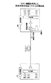
FIG. 9 is a diagram illustrating an example of a method for supplying excitation light to a transmission line. In this method, pumping
[0047]
The
[0048]
Each
[0049]
The
[0050]
Next, the operation of the Raman amplifier configured as described above will be described with reference to FIG. In the above configuration, the pumping lights P1 to PQ generated by the pumping
[0051]
FIG. 10 is a diagram illustrating another example of a method for supplying excitation light to a transmission line. In this method, pumping lights P1 to Pm are supplied by each
The
[0052]
Each
[0053]
The optical circulator 34 includes three input / output ports (ac ports). Here, the light input from the a port is guided to the b port, the light input from the b port is guided to the c port, and the light input from the c port is guided to the a port. Therefore, the optical circulator 34 guides the signal lights S1 to Sn input through the optical fiber on the
[0054]
Next, the operation of the Raman amplifier configured as described above will be described with reference to FIG. In the above configuration, the pumping lights P1 to Pm generated by the pumping
[0055]
FIG. 11 is a modification of the method shown in FIG. In this method, pumping lights P1 to Pm are supplied by each
[0056]
In the systems shown in FIGS. 9 to 11, it is basically desirable that the optical spectrum width of each excitation light be narrow. It is desirable that at least the spectrum width of the excitation light (for example, excitation light PQ + 1 to Pm) arranged in the band where the signal light is arranged is about the same as that of the signal light. The optical spectrum width of each excitation light is adjusted by, for example, an optical fiber grating.
[0057]
By the way, in the wavelength division multiplexing transmission system, it is generally desirable that the level of each signal light included in the wavelength division multiplexed light is equalized. In order to equalize the level of each signal light included in the wavelength multiplexed light, it is necessary to adjust the gain of each amplifier. Hereinafter, a method for adjusting the gain of each Raman amplifier will be described.
[0058]
FIG. 12 is a diagram for explaining the function of adjusting the gain in each
[0059]
The
[0060]
The
[0061]
In the case where a part of the pumping light (pumping light PQ + 1 to Pm) is generated by the
[0062]
As described above, in the system of this embodiment, the wavelength deviation of the gain in each Raman amplifier is reduced by appropriately adjusting the optical powers of the pumping lights P1 to Pm.
[0063]
FIG. 13 is a diagram for explaining a method of adjusting the optical S / N ratio of the signal lights S1 to Sn. The optical S / N ratio of the signal lights S1 to Sn is basically controlled by adjusting the optical power of the signal lights S1 to Sn generated by the
[0064]
The
[0065]
When receiving the instruction from the
[0066]
Thus, in the optical transmission system of this embodiment, the gain by Raman amplification and the optical S / N ratio of signal light are individually adjusted. That is, the optical power of each pumping light is appropriately adjusted (pumping light pre-emphasis) to reduce the deviation of the Raman gain depending on the wavelength, and the deviation of the optical S / N ratio of the plurality of signal lights is reduced. Therefore, the optical power of each signal light is appropriately adjusted (signal light pre-emphasis).
[0067]
As described above, in the Raman amplifier of this embodiment, a part of the signal light (for example, S1 to Sr in FIG. 3) works as excitation light for the signal light on the longer wavelength side. However, since the optical power of each signal light is sufficiently smaller than that of the pump light, the gain generated by the signal light is smaller than the gain generated by the pump light. Therefore, the gain of the Raman amplifier is generally adjusted to a desired characteristic by controlling the optical power of each pumping light. At this time, the optical power of the signal light may be finely adjusted as necessary. Further, instead of the S / N detection circuit, it is also possible to use the code error rate of the optical receiver for each wavelength.
[0068]
Next, a method for improving the transmission performance of the optical transmission system using the characteristics of Raman amplification will be described.
FIG. 14 is a configuration diagram of an optical transmission system provided with a mixed transmission line fiber. In this system, a mixed transmission line fiber is used as an optical fiber for transmitting wavelength division multiplexed light. The mixed transmission line fiber includes a first optical fiber and a second optical fiber having a smaller mode field diameter (effective cross-sectional area or core diameter) than that of the first optical fiber. Here, as one embodiment, it is desirable that the first optical fiber has positive dispersion and the second optical fiber has negative dispersion. Then, when the signal light is transmitted from the
[0069]
FIG. 15 is a configuration diagram of a Raman amplifier in the system shown in FIG. Here, any one of a plurality of Raman amplifiers provided on the transmission line is shown.
[0070]
The
[0071]
Further, in this system, nonlinear effects on the optical transmission line can be suppressed. Here, as is well known, the nonlinear effect on the optical transmission line increases as the mode field diameter of the optical fiber decreases, and increases as the optical power of the signal light increases. However, in this system, when the optical power of the signal light is large, the nonlinear effect is small because the light is propagated through the first optical fiber having a relatively large mode field diameter. Further, since the signal light is sufficiently attenuated when it reaches the second optical fiber having a small mode field diameter, the nonlinear effect generated in the second optical fiber is also small. That is, nonlinear effects are suppressed in all transmission paths, and transmission waveform distortion is reduced.
[0072]
As described above, when the mixed transmission path composed of the first and second optical fibers is used, the optical S / N ratio of the signal light is improved and the distortion of the signal waveform due to the nonlinear effect is suppressed. The ratio of the length of the first optical fiber to the length of the second optical fiber is, for example, 2: 1. The effective areas of the first and second optical fibers are, for example, about 110 micrometer square and 20 micrometer square, respectively.
[0073]
In the examples shown in FIGS. 14 and 15, the mixed transmission line fiber is composed of two types of optical fibers having different mode field diameters, but the present invention is not limited to this. That is, the mixed transmission line fiber may be composed of three or more types of optical fibers. For example, in the example shown in FIGS. 16 and 17, each mixed transmission line fiber is composed of first to third optical fibers. In this case, the mode field diameter of the first optical fiber is the largest, and the mode field diameter of the third optical fiber is the smallest. As described above, the mixed transmission line fiber may be configured by connecting a plurality of types of optical fibers so that the mode field diameter gradually decreases in the direction in which the signal light is transmitted.
[0074]
By the way, in Raman amplification, as described with reference to FIGS. 3 to 6, when pump light is supplied to an optical fiber, gain is increased in a wavelength band shifted from the wavelength of the pump light to the longer wavelength side by the amount of Raman shift. can get. At this time, if light exists in the gain wavelength band, the light is amplified. For example, in FIG. 4, when pumping light P1 to PQ is supplied to the optical fiber, light (including signal light and pumping light) arranged in the wavelength band λ2 to λ3 is amplified. At this time, the light arranged in the wavelength band λ2 to λ3 is amplified by absorbing a part of the energy given as the excitation light P1 to PQ.
[0075]
As described above, the Raman amplification occurs when the energy given as the excitation light is absorbed by the light arranged on the longer wavelength side than the wavelength of the excitation light. At this time, when a part of the energy of the pumping light is absorbed by the other light, the optical power of the pumping light decreases accordingly. On the other hand, the optical power of the excitation light hardly decreases unless a part of the energy is absorbed by other light. That is, the optical power of the excitation light may vary depending on whether a part of the energy is absorbed by other light.
[0076]
This problem is not limited to the excitation light. For example, in FIG. 4, the energy of the light arranged in the wavelength band λ1 to λ2 is absorbed by the light arranged in the wavelength band λ2 to λ3, and the energy of the light arranged in the wavelength band λ2 to λ3 is the wavelength. It is absorbed by the light arranged in the bands λ3 to λ4. However, the energy of light arranged in the wavelength band λ3 to λ4 is not absorbed by other light. As a result, the gain in the wavelength band λ3 to λ4 may become larger than necessary. Alternatively, the level of the signal light arranged in the wavelength band λ3 to λ4 may become higher than necessary.
[0077]
In the system of this embodiment, in order to solve the above-described problem, as shown in FIG. 18, auxiliary lights A1 to At are arranged on the longer wavelength side than the wavelength band in which the signal lights S1 to Sn are arranged. As a result, the energy of the signal lights Sr to Sn arranged in the wavelength bands λ3 to λ4 is absorbed by the auxiliary lights A1 to At. That is, the gain in the wavelength band λ3 to λ4 is appropriately suppressed.
[0078]
The auxiliary lights A1 to At can also be used in a system in which three or more stages of Raman amplification are performed. FIG. 19 shows an example in which auxiliary lights A1 to At are arranged in a system in which three-stage Raman amplification is performed.
[0079]
The auxiliary lights A1 to At may be generated by the
[0080]
The auxiliary lights A1 to At may be arranged according to the ITU-T grid shown in FIG. 7A, similarly to the signal light or the excitation light. In addition, the auxiliary lights A1 to At may be arranged at a constant frequency interval, like the excitation light.
[0081]
Further, the auxiliary lights A1 to At may be used as a carrier wave for transmitting a monitoring signal for the
[0082]
Further, the optical power of the auxiliary lights A1 to At may be adjusted according to an instruction from the
[0083]
FIG. 24 is a block diagram of the optical transmission system of the present invention. In this system, a plurality of
[0084]
As is well known, the gain wavelength band of a rare earth-doped fiber amplifier varies depending on the material injected into the optical fiber. However, the effective gain wavelength band width of the rare earth doped fiber amplifier is usually about 30 to 40 nm. Therefore, in order to amplify wavelength multiplexed signal light having a wavelength band of 100 nm or more, it is necessary to use a plurality of rare earth doped fiber amplifiers having different gain wavelength bands. In the example shown in FIG. 24, rare earth doped fiber amplifiers 81a to 81n having different gain wavelength bands are provided at the terminal stations. The wavelength-division multiplexed signal light is demultiplexed for each gain wavelength band of the rare-earth doped fiber amplifiers 81a to 81n by a demultiplexer (not shown) at the
In the system of the present embodiment, the plurality of excitation lights are arranged so as to satisfy the following expression (1). Here, “Δfr” is a Raman shift amount, “Δfe” is an interval at which the excitation light is to be arranged, and “n” is an arbitrary integer.
[0085]
Δfr = n · Δfe (1)
FIG. 25A is a correspondence table showing gain bandwidths when “n = 1 to 6” is substituted into the above equation (1). The Raman shift amount (Δfr) is 13.2 THz. In this case, when 1 to 6 is given as “n”, 13.2 to 2.2 THz is obtained as the interval (Δfe) where the excitation light should be arranged. These intervals are 105.7 to 17.6 nm, respectively, when converted to wavelengths in the vicinity of 1550 nm. Here, the gain bandwidth of the rare earth doped fiber amplifier is 30 to 40 nm, respectively. Therefore, in order to reduce the number of rare earth doped fiber amplifiers 81a to 81n as much as possible, “3” is preferable as “n” to be given to the above equation (1).
[0086]
FIG. 26 shows an embodiment in which excitation light is arranged based on the above equation (1). Here, the case where “n = 3” is given in the above equation (1) is shown. That is, the excitation lights P1 to P10 are arranged every 4.4 THz.
[0087]
The wavelength band in which the signal light is arranged is 1435 to 1667 nm in this embodiment. Then, this signal light wavelength band is collectively amplified by each
[0088]
Further, according to the above equation (1), each pump light is arranged so that the peak wavelength of the Raman gain due to each pump light matches the wavelength of the corresponding pump light. For example, the wavelength at which the Raman gain due to the pumping light P1 reaches the peak coincides with the wavelength of the pumping light P4, and the wavelength at which the Raman gain due to the pumping light P2 reaches the peak coincides with the wavelength of the pumping light P5. Therefore, it is expected that the work (pre-emphasis) of adjusting the optical power of each pumping light to equalize the Raman gain is facilitated.
[0089]
In the system of another form of the present embodiment, the plurality of excitation lights are arranged so as to satisfy the following expression (2). Here, “Δfr” is a Raman shift amount, “Δfe” is an interval at which the excitation light is to be arranged, and “n” is an arbitrary integer.
[0090]
Δfr = (n + 0.5) · Δfe (2)
FIG. 25B is a correspondence table showing gain bandwidths when “n = 1 to 6” is substituted into the above equation (2). As shown in FIG. 25 (b), when 1 to 6 are given as “n”, 8.8 to 2.0 THz are obtained as the intervals (Δfe) where the excitation light should be arranged, respectively. These intervals are 70.5 to 16.3 nm when converted to wavelengths in the vicinity of 1550 nm. Here, considering that the gain bandwidth of the rare earth doped fiber amplifier is 30 to 40 nm, “2” or “3” is preferable as “n” to be given to the above equation (2).
[0091]
FIG. 27 shows an embodiment in the case where the excitation light is arranged based on the above (2). Here, the case where “n = 3” is given in the above equation (2) is shown. That is, the excitation lights P1 to P10 are arranged every 3.77 THz. Also in this embodiment, the signal light wavelength band is demultiplexed into a plurality of wavelength bands (S ++ band to L ++ band) as in the method shown in FIG. Amplified by 81a-81n.
[0092]
According to the above equation (2), the peak wavelength of Raman gain due to each pumping light is approximately halfway between the wavelengths of the nth pumping light and the (n + 1) th pumping light when viewed from the pumping light. It becomes. For example, the wavelength at which the Raman gain due to the pumping light P1 reaches a peak is approximately halfway between the wavelengths of the pumping light P4 and the pumping light P5. In this embodiment, the wavelength bands (S ++ band to L ++ band) partitioned by the pumping lights P4 to P10 are amplified by the corresponding rare earth doped fiber amplifiers 81a to 81n. Therefore, the peak frequency of the Raman gain due to each pumping light is approximately the center of the gain wavelength band of the corresponding rare earth-doped fiber amplifier 81a to 81n.
Therefore, a stable amplification operation is expected.
[0093]
Finally, a method for arranging supervisory control light for transmitting supervisory signals for the
The supervisory control light is a carrier wave that transmits a supervisory signal for monitoring the transmission system. The transmission speed of the monitoring signal is sufficiently low compared with the signal transmitted by the signal light. For example, the transmission speed of a signal transmitted by signal light is about 10 Gbps, while that of a monitoring signal is about several tens of kbps to several Mbps. Therefore, the supervisory control light can be received even if its optical S / N ratio is smaller than that of the signal light.
[0094]
By the way, the optical power of the excitation light is sufficiently larger than that of the signal light. For this reason, the optical spectrum width of the excitation light is quite wide, and disturbances (crosstalk, four-wave mixing, etc.) are large in the vicinity of the excitation light. That is, the optical S / N ratio is expected to deteriorate in the vicinity of the excitation light. For this reason, in the system according to the present embodiment, as shown in FIG. 28, monitoring control light having resistance to the optical S / N ratio is arranged in the vicinity of the excitation light. Thereby, the wavelength band far from the excitation light is not used by the monitoring control light, and the signal light can be arranged efficiently.
[0095]
(Appendix 1) A Raman amplifier that amplifies wavelength multiplexed signal light in which a plurality of signal lights are multiplexed by wavelength multiplexing,
A transmission path for propagating the wavelength-division multiplexed signal light and the first pumping light for amplifying the wavelength-multiplexed signal light;
A light source that generates second excitation light for amplifying the wavelength-multiplexed signal light;
Optical means for supplying the second excitation light generated by the light source to the transmission path,
A Raman amplifier in which at least one of the first pumping light and the second pumping light is disposed in a band of the wavelength multiplexed signal light.
(Appendix 2) A Raman amplifier that amplifies wavelength multiplexed signal light in which a plurality of signal lights are multiplexed by wavelength multiplexing,
A transmission path for propagating the wavelength multiplexed signal light;
A light source that generates first excitation light disposed within the band of the wavelength multiplexed signal light and second excitation light disposed outside the band of the wavelength multiplexed signal light;
Optical means for supplying the first excitation light and the second excitation light generated by the light source to the transmission path;
Having a Raman amplifier.
(Appendix 3) The Raman amplifier according to
The wavelength of the second excitation light is shorter than the wavelength of the wavelength multiplexed signal light.
(Appendix 4) The Raman amplifier according to
The first excitation light and the second excitation light are arranged at equal frequency intervals.
(Appendix 5) The Raman amplifier according to
The first excitation light is arranged according to an ITU-T grid.
(Appendix 6) The Raman amplifier according to
Each of the first excitation light and the second excitation light is composed of two or more waves.
(Appendix 7) The Raman amplifier according to
The first excitation light is amplified by the second excitation light.
(Appendix 8) A Raman amplifier that amplifies wavelength multiplexed signal light in which a plurality of signal lights are multiplexed by wavelength multiplexing,
A transmission path for propagating the wavelength multiplexed signal light and the first pumping light;
A light source that generates second excitation light disposed within the band of the wavelength multiplexed signal light and third excitation light disposed outside the band of the wavelength multiplexed signal light;
Optical means for supplying the second excitation light and the third excitation light generated by the light source to the transmission path;
Having a Raman amplifier.
(Supplementary Note 9) A Raman amplifier is provided between the first terminal device and the second terminal device, and wavelength multiplexed signal light obtained by multiplexing a plurality of signal lights by wavelength multiplexing is the first terminal station. An optical transmission system transmitted from a device to the second terminal device,
The first terminal device is
A signal light source for generating the wavelength-multiplexed signal light;
A first excitation light source for generating first excitation light,
The Raman amplifier is
A transmission path for propagating the wavelength multiplexed signal light and the first pumping light;
A second excitation light source for generating second excitation light;
Optical means for supplying the second excitation light generated by the second excitation light source to the transmission path,
At least a part of the first pumping light is arranged in a band of the wavelength multiplexed signal light,
An optical transmission system in which the optical powers of the first and second pump lights are adjusted so that gains by the Raman amplifier are equalized.
(Supplementary Note 10) A Raman amplifier is provided between the first terminal device and the second terminal device, and wavelength multiplexed signal light obtained by multiplexing a plurality of signal lights by wavelength multiplexing is the first terminal station. An optical transmission system transmitted from a device to the second terminal device,
The first terminal device is
A signal light source for generating the wavelength-multiplexed signal light,
The Raman amplifier is
A transmission path for propagating the wavelength multiplexed signal light;
A first pumping light source for generating first pumping light arranged in the band of the wavelength multiplexed signal light;
A second pumping light source for generating a second pumping light disposed outside the band of the wavelength multiplexed signal light;
Optical means for supplying the first excitation light generated by the first excitation light source and the second excitation light generated by the second excitation light source to the transmission line,
An optical transmission system in which the optical powers of the first and second pump lights are adjusted so that gains by the Raman amplifier are equalized.
(Appendix 11) The optical transmission system according to Appendix 9 or
The optical powers of the first and second excitation lights are adjusted according to instructions from the first or second terminal device.
(Supplementary note 12) The optical transmission system according to supplementary note 9 or
The power of the signal light is adjusted based on the optical S / N ratio of each signal light detected by the second terminal device.
(Additional remark 13) It is the optical amplification method which amplifies the wavelength multiplexing signal light by which the several signal light was multiplexed by wavelength multiplexing using a Raman amplifier,
An optical amplification method for supplying pump light having a wavelength shorter than the wavelength of the wavelength-multiplexed signal light and pump light in a band in which the wavelength-multiplexed signal light is disposed to the transmission path through which the wavelength-multiplexed signal light is propagated.
(Supplementary note 14) A Raman amplifier that amplifies wavelength multiplexed signal light in which a plurality of signal lights are multiplexed by wavelength multiplexing,
A transmission path for propagating auxiliary light having a wavelength longer than the wavelength-multiplexed signal light and the wavelength-multiplexed signal light;
A light source that generates excitation light for amplifying the wavelength-multiplexed signal light;
Optical means for supplying excitation light generated by the light source to the transmission path;
Having a Raman amplifier.
(Supplementary note 15) A Raman amplifier that amplifies wavelength multiplexed signal light in which a plurality of signal lights are multiplexed by wavelength multiplexing,
A transmission path for propagating the wavelength multiplexed signal light;
A light source for generating auxiliary light having a wavelength longer than the wavelength of the wavelength multiplexed signal light and the excitation light for amplifying the wavelength multiplexed signal light;
Optical means for supplying excitation light and auxiliary light generated by the light source to the transmission line;
Having a Raman amplifier.
(Supplementary note 16) The Raman amplifier according to
The auxiliary lights are arranged at equal frequency intervals.
(Supplementary note 17) The Raman amplifier according to
The auxiliary light is arranged according to an ITU-T grid.
(Supplementary note 18) The Raman amplifier according to
The auxiliary light is composed of two or more waves.
(Supplementary note 19) The Raman amplifier according to
The auxiliary light is disposed so as to absorb energy of a part of the plurality of signal lights.
(Supplementary note 20) A Raman amplifier is provided between the first terminal device and the second terminal device, and the wavelength multiplexed signal light obtained by multiplexing a plurality of signal lights by wavelength multiplexing is the first terminal station. An optical transmission system transmitted from a device to the second terminal device,
The first terminal device is
A signal light source for generating the wavelength-multiplexed signal light;
An auxiliary light source for generating auxiliary light having a wavelength longer than the wavelength of the wavelength multiplexed signal light,
The Raman amplifier is
A transmission path for propagating the wavelength multiplexed signal light and auxiliary light;
An excitation light source for generating excitation light for amplifying the wavelength multiplexed signal light;
Optical means for supplying excitation light generated by the excitation light source to the transmission path,
An optical transmission system in which the optical power of the auxiliary light is adjusted so that the gain by the Raman amplifier is equalized.
(Supplementary Note 21) A Raman amplifier is provided between the first terminal device and the second terminal device, and wavelength multiplexed signal light obtained by multiplexing a plurality of signal lights by wavelength multiplexing is the first terminal station. An optical transmission system transmitted from a device to the second terminal device,
The first terminal device is
A signal light source for generating the plurality of signal lights,
The Raman amplifier is
A transmission path for propagating the wavelength multiplexed signal light;
An excitation light source for generating excitation light for amplifying the wavelength multiplexed signal light;
An auxiliary light source for generating auxiliary light having a wavelength longer than the wavelength of the wavelength multiplexed signal light;
Optical means for supplying excitation light generated by the excitation light source and auxiliary light generated by the auxiliary light source to the transmission path;
An optical transmission system in which the optical power of the auxiliary light is adjusted so that the gain by the Raman amplifier is equalized.
(Appendix 22) The optical transmission system according to
The optical power of the auxiliary light is adjusted according to an instruction from the first or second terminal device.
(Supplementary note 23) The optical transmission system according to
A monitoring signal for monitoring the state of the transmission system is carried by the auxiliary light.
(Supplementary Note 24) An optical transmission system in which a wavelength multiplexed signal light obtained by multiplexing a plurality of signal lights by wavelength multiplexing is amplified by a Raman amplifier, wherein the Raman amplifier has a frequency interval of 1 / n of a Raman shift amount. An optical transmission system (n is an integer) that amplifies the wavelength-division multiplexed signal light using a plurality of pumping lights arranged in (1).
(Supplementary Note 25) An optical transmission system in which a wavelength multiplexed signal light obtained by multiplexing a plurality of signal lights by wavelength multiplexing is amplified by a Raman amplifier and a rare earth doped fiber amplifier,
The Raman amplifier amplifies the wavelength-multiplexed signal light using a plurality of pump lights arranged at a frequency interval of 1 / n of a Raman shift amount,
The rare earth-doped fiber amplifier is composed of a plurality of amplification units corresponding to the plurality of pump lights, and each amplification unit amplifies signal light in a corresponding wavelength band (n is an integer).
(Supplementary note 26) An optical transmission system in which a wavelength multiplexed signal light obtained by multiplexing a plurality of signal lights by wavelength multiplexing is amplified by a Raman amplifier and a rare earth doped fiber amplifier,
The Raman amplifier amplifies the wavelength-multiplexed signal light using a plurality of pump lights arranged at a frequency interval of (n + 0.5) times the Raman shift amount,
The rare earth-doped fiber amplifier is composed of a plurality of amplification units corresponding to the plurality of pump lights, and each amplification unit amplifies signal light in a corresponding wavelength band (n is an integer).
(Supplementary note 27) An optical transmission system in which wavelength multiplexed signal light obtained by multiplexing a plurality of signal lights by wavelength multiplexing is amplified by a Raman amplifier,
The Raman amplifier amplifies the wavelength-multiplexed signal light using pumping light arranged in a band of the wavelength-multiplexed signal light,
A monitoring signal for monitoring the state of the transmission system is arranged in the vicinity of the excitation light arranged in the band of the wavelength multiplexed signal light.
[0096]
【The invention's effect】
According to the present invention, a gain wavelength bandwidth wider than the Raman shift amount can be obtained using a Raman amplifier, and a large-capacity wavelength division multiplexing transmission system is realized. Moreover, since the auxiliary light for absorbing the energy of the signal light is arranged on the longer wavelength side than the signal light, it is possible to avoid that a part of the signal light is amplified more than necessary. Furthermore, since the rare earth doped fiber amplifier is used corresponding to the arrangement of the pumping light of the Raman amplifier, the combined use of the Raman amplifier and the rare earth doped fiber amplifier becomes easy.
[Brief description of the drawings]
FIG. 1 is a configuration diagram of an optical transmission system provided with a Raman amplifier of the present invention.
FIG. 2 is a configuration diagram of a Raman amplifier according to the present embodiment.
FIG. 3 is a diagram illustrating an outline of a Raman amplifier according to the present embodiment.
FIG. 4 is a diagram for explaining the operation of the Raman amplifier of the present embodiment.
FIG. 5 is a diagram for explaining the concept of Raman amplification for obtaining a wider gain wavelength bandwidth;
6 is a diagram for explaining the operation of the Raman amplifier shown in FIG. 5;
FIG. 7 is a diagram illustrating a method for setting signal light and excitation light.
FIG. 8 is a diagram illustrating a method for arranging excitation light.
FIG. 9 is a diagram illustrating an example of a method for supplying excitation light to a transmission line.
FIG. 10 is a diagram illustrating another example of a method for supplying excitation light to a transmission line.
11 is a modification of the method shown in FIG.
FIG. 12 is a diagram illustrating a function of adjusting a gain in a Raman amplifier.
FIG. 13 is a diagram illustrating a method for adjusting the optical S / N ratio of signal light.
FIG. 14 is a configuration diagram (No. 1) of an optical transmission system provided with a mixed transmission line fiber;
15 is a configuration diagram of a Raman amplifier in the system shown in FIG.
FIG. 16 is a configuration diagram (No. 2) of an optical transmission system provided with a mixed transmission line fiber;
17 is a configuration diagram of a Raman amplifier in the system shown in FIG.
FIG. 18 is a diagram for explaining the arrangement of auxiliary light (part 1);
FIG. 19 is a diagram (part 2) illustrating the arrangement of auxiliary light;
FIG. 20 is a diagram (No. 1) illustrating a method of supplying auxiliary light;
FIG. 21 is a diagram (No. 2) illustrating a method for supplying auxiliary light;
FIG. 22 is a diagram (No. 3) illustrating a method of supplying auxiliary light;
FIG. 23 is a diagram (No. 4) illustrating a method of supplying auxiliary light;
FIG. 24 is a configuration diagram of an optical transmission system in which a Raman amplifier and a rare earth doped fiber amplifier are mixed.
FIG. 25 is a correspondence table for determining the arrangement of excitation light.
FIG. 26 is a diagram (part 1) illustrating an arrangement example of excitation light;
FIG. 27 is a diagram (part 2) illustrating an arrangement example of excitation light;
FIG. 28 is a diagram illustrating a method of arranging monitoring control light.
FIG. 29 is a configuration diagram of a general optical repeater transmission system.
FIG. 30 is a diagram illustrating the principle of Raman amplification.
FIG. 31 is a configuration diagram of a wavelength division multiplexing optical transmission system using Raman amplification.
FIG. 32 is a diagram illustrating an amplification operation of an existing Raman amplifier.
[Explanation of symbols]
10, 20 Terminal
11, 22 Optical transmitter
12, 21 Optical receiver
30 Raman amplifier
31, 42 Excitation light source
32, 33 multiplexer
34 Optical circulator
41 Signal light source
43 MUX
71 Auxiliary light source
81a-81n rare earth doped fiber amplifier
Claims (2)
上記ラマン増幅器は、ラマンシフト量のn分の1の周波数間隔で配置される複数の励起光を用いて上記波長多重信号光を増幅し、上記希土類ドープファイバ増幅器は、上記複数の励起光に対応する複数の増幅ユニットから構成され、各増幅ユニットがそれぞれ対応する波長帯域の信号光を増幅する光伝送システム。ただし、nは3とする。An optical transmission system in which a wavelength multiplexed signal light obtained by multiplexing a plurality of signal lights by wavelength multiplexing is amplified by a Raman amplifier and a rare earth doped fiber amplifier,
The Raman amplifier amplifies the wavelength multiplexed signal light using a plurality of pump lights arranged at a frequency interval of 1 / n of the Raman shift amount, and the rare earth doped fiber amplifier corresponds to the plurality of pump lights. An optical transmission system that includes a plurality of amplification units that amplify signal light in a corresponding wavelength band. However, n is 3 .
上記ラマン増幅器は、ラマンシフト量の(n+0.5)分の1の周波数間隔で配置される複数の励起光を用いて上記波長多重信号光を増幅し、上記希土類 ドープファイバ増幅器は、上記複数の励起光に対応する複数の増幅ユニットから構成され、各増幅ユニットがそれぞれ対応する波長帯域の信号光を増幅する光伝送システム。ただし、nは2または3とする。An optical transmission system in which a wavelength multiplexed signal light obtained by multiplexing a plurality of signal lights by wavelength multiplexing is amplified by a Raman amplifier and a rare earth doped fiber amplifier,
The Raman amplifier amplifies the wavelength-multiplexed signal light using a plurality of pump lights arranged at a frequency interval of (n + 0.5) / (Raman shift amount), and the rare earth-doped fiber amplifier An optical transmission system that includes a plurality of amplification units corresponding to excitation light, and each amplification unit amplifies signal light in a corresponding wavelength band. However, n is 2 or 3 .
Priority Applications (3)
| Application Number | Priority Date | Filing Date | Title |
|---|---|---|---|
| JP2001030053A JP4551007B2 (en) | 2001-02-06 | 2001-02-06 | Raman amplifier and optical transmission system using the same |
| US09/935,575 US6639715B2 (en) | 2001-02-06 | 2001-08-24 | Raman amplifier and optical transmission system using the amplifier |
| FR0111565A FR2820550B1 (en) | 2001-02-06 | 2001-09-06 | RAMAN AMPLIFIER AND OPTICAL TRANSMISSION SYSTEM USING THE AMPLIFIER |
Applications Claiming Priority (1)
| Application Number | Priority Date | Filing Date | Title |
|---|---|---|---|
| JP2001030053A JP4551007B2 (en) | 2001-02-06 | 2001-02-06 | Raman amplifier and optical transmission system using the same |
Related Child Applications (1)
| Application Number | Title | Priority Date | Filing Date |
|---|---|---|---|
| JP2010117620A Division JP4695713B2 (en) | 2010-05-21 | 2010-05-21 | Raman amplifier and optical transmission system using the same |
Publications (2)
| Publication Number | Publication Date |
|---|---|
| JP2002229084A JP2002229084A (en) | 2002-08-14 |
| JP4551007B2 true JP4551007B2 (en) | 2010-09-22 |
Family
ID=18894320
Family Applications (1)
| Application Number | Title | Priority Date | Filing Date |
|---|---|---|---|
| JP2001030053A Expired - Lifetime JP4551007B2 (en) | 2001-02-06 | 2001-02-06 | Raman amplifier and optical transmission system using the same |
Country Status (3)
| Country | Link |
|---|---|
| US (1) | US6639715B2 (en) |
| JP (1) | JP4551007B2 (en) |
| FR (1) | FR2820550B1 (en) |
Families Citing this family (35)
| Publication number | Priority date | Publication date | Assignee | Title |
|---|---|---|---|---|
| US6631018B1 (en) * | 1997-08-27 | 2003-10-07 | Nortel Networks Limited | WDM optical network with passive pass-through at each node |
| DE60134981D1 (en) * | 2001-09-28 | 2008-09-04 | Ipg Fibertech S R L | Method for generating optical radiation suitable for use in a Raman amplification process and pump source for Raman amplifier |
| JP2003107543A (en) * | 2001-09-28 | 2003-04-09 | Sumitomo Electric Ind Ltd | Raman amplification method, Raman amplifier, and optical transmission system |
| JP2003169037A (en) * | 2001-11-29 | 2003-06-13 | Nec Corp | WDM transmission equipment |
| JP2003188831A (en) * | 2001-12-20 | 2003-07-04 | Fujitsu Ltd | Optical transmission system and optical repeater |
| US7853333B2 (en) | 2002-04-08 | 2010-12-14 | Ardian, Inc. | Methods and apparatus for multi-vessel renal neuromodulation |
| JP2004086143A (en) * | 2002-06-28 | 2004-03-18 | Sumitomo Electric Ind Ltd | Optical transmission system |
| JP3992565B2 (en) * | 2002-08-27 | 2007-10-17 | 富士通株式会社 | Optical transmission system |
| CN100388658C (en) * | 2002-09-12 | 2008-05-14 | 中兴通讯股份有限公司 | Device and method for adjusting average slope of gain spectrum of multi-pump Raman amplifier |
| JP4184046B2 (en) | 2002-11-18 | 2008-11-19 | 富士通株式会社 | Raman amplifier |
| JP4115814B2 (en) | 2002-11-26 | 2008-07-09 | 富士通株式会社 | Wavelength arrangement method of signal light, and optical transmission apparatus and wavelength division multiplexing optical transmission system using the method |
| AU2002368474A1 (en) * | 2002-12-19 | 2004-07-14 | Pirelli And C. S.P.A. | Multiple stage raman optical amplifier |
| US7145716B2 (en) * | 2002-12-19 | 2006-12-05 | Pirelli & C. S.P.A. | Multiple stage Raman optical amplifier |
| JP4176527B2 (en) | 2003-03-31 | 2008-11-05 | 富士通株式会社 | Raman amplifier and optical transmission system using the same |
| DE60301549T2 (en) * | 2003-04-14 | 2006-01-19 | Alcatel | Raman optical amplifier and pump modulation method |
| US7619812B2 (en) * | 2004-08-11 | 2009-11-17 | Siemens Aktiengesellschaft | Method and arrangement for the rapid adjustment of the tilt of optical WDM signals |
| US20070258717A1 (en) * | 2006-05-01 | 2007-11-08 | Masaaki Hirano | Optical device and wavelength conversion method and optical fiber suitable for them |
| JP2008078728A (en) * | 2006-09-19 | 2008-04-03 | Fujitsu Ltd | Optical transmission equipment |
| JP5012478B2 (en) * | 2006-12-27 | 2012-08-29 | 富士通株式会社 | Distributed Raman amplifier and WDM optical transmission system |
| JP4431179B2 (en) * | 2008-02-04 | 2010-03-10 | 富士通株式会社 | Distributed Raman amplification system, start-up method thereof, and optical apparatus |
| US7869673B2 (en) * | 2008-08-29 | 2011-01-11 | Xtera Communications, Inc. | Remote larger effective area optical fiber |
| JP5378861B2 (en) * | 2009-03-31 | 2013-12-25 | 古河電気工業株式会社 | Optical fiber laser |
| EP2365654B1 (en) * | 2010-03-10 | 2019-05-29 | Ofs Fitel Llc, A Delaware Limited Liability Company | Multicore fiber transmission systems and methods |
| EP2548056B1 (en) * | 2010-03-16 | 2021-05-05 | OFS Fitel, LLC | Multicore transmission and amplifier fibers and schemes for launching pump light to amplifier cores |
| US20120002283A1 (en) * | 2010-06-30 | 2012-01-05 | Chongjin Xie | Method and apparatus for raman co-pumps |
| US8903211B2 (en) * | 2011-03-16 | 2014-12-02 | Ofs Fitel, Llc | Pump-combining systems and techniques for multicore fiber transmissions |
| US9059799B2 (en) * | 2011-04-21 | 2015-06-16 | Futurewei Technologies, Inc. | Apparatus and method to calculate a noise figure of an optical amplifier for wavelength channels in a partial-fill scenario to account for channel loading |
| US9905990B1 (en) | 2014-04-17 | 2018-02-27 | Alakai Defense Systems, Inc. | Background removal from Raman spectra by an intracavity active-tuning element for a laser |
| US11165501B2 (en) * | 2016-02-19 | 2021-11-02 | Mitsubishi Electric Corporation | Excitation light source apparatus and optical transmission system |
| US10218454B2 (en) * | 2017-03-13 | 2019-02-26 | Google Llc | Open, modular, and scalable optical line system |
| WO2019039590A1 (en) * | 2017-08-25 | 2019-02-28 | 日本電信電話株式会社 | Optical amplification repeating system, and optical amplifier |
| US20220123517A1 (en) * | 2018-12-28 | 2022-04-21 | Nlight, Inc. | Optical fiber devices and methods for reducing stimulated raman scattering (srs) light intensity in signal combined systems |
| WO2021055844A1 (en) * | 2019-09-19 | 2021-03-25 | Ofs Fitel, Llc | Parallel o-band amplifier |
| JP7671007B2 (en) * | 2021-10-06 | 2025-05-01 | 日本電信電話株式会社 | Optical distributed amplifier and optical distributed amplification system |
| JP2024038573A (en) * | 2022-09-08 | 2024-03-21 | 富士通株式会社 | Optical transmission device, optical transmission system, and control method for Raman amplifier |
Family Cites Families (8)
| Publication number | Priority date | Publication date | Assignee | Title |
|---|---|---|---|---|
| JP2757912B2 (en) * | 1996-01-16 | 1998-05-25 | 日本電気株式会社 | Optical fiber communication system |
| JPH1073852A (en) * | 1996-09-02 | 1998-03-17 | Nippon Telegr & Teleph Corp <Ntt> | Optical amplification transmission system |
| EP2315073B1 (en) * | 1998-07-23 | 2014-12-31 | The Furukawa Electric Co., Ltd. | Raman amplifier and Raman amplification method |
| JP4115027B2 (en) * | 1998-07-23 | 2008-07-09 | 古河電気工業株式会社 | Excitation light generation means, Raman amplifier and optical repeater using the same |
| US6163636A (en) * | 1999-01-19 | 2000-12-19 | Lucent Technologies Inc. | Optical communication system using multiple-order Raman amplifiers |
| US6147794A (en) * | 1999-02-04 | 2000-11-14 | Lucent Technologies, Inc. | Raman amplifier with pump source for improved performance |
| JP3600063B2 (en) * | 1999-04-30 | 2004-12-08 | 日本電信電話株式会社 | Optical fiber communication system using distributed amplification fiber Raman amplifier |
| US6424455B1 (en) * | 2000-10-03 | 2002-07-23 | Tycom (Us) Inc. | Wide bandwidth fiber raman amplifier |
-
2001
- 2001-02-06 JP JP2001030053A patent/JP4551007B2/en not_active Expired - Lifetime
- 2001-08-24 US US09/935,575 patent/US6639715B2/en not_active Expired - Lifetime
- 2001-09-06 FR FR0111565A patent/FR2820550B1/en not_active Expired - Lifetime
Also Published As
| Publication number | Publication date |
|---|---|
| FR2820550A1 (en) | 2002-08-09 |
| US6639715B2 (en) | 2003-10-28 |
| FR2820550B1 (en) | 2005-05-27 |
| JP2002229084A (en) | 2002-08-14 |
| US20020105715A1 (en) | 2002-08-08 |
Similar Documents
| Publication | Publication Date | Title |
|---|---|---|
| JP4551007B2 (en) | Raman amplifier and optical transmission system using the same | |
| US6771413B2 (en) | Optical transmission systems including optical amplifiers, apparatuses and methods | |
| US6882466B1 (en) | Optical amplifier | |
| US5696615A (en) | Wavelength division multiplexed optical communication systems employing uniform gain optical amplifiers | |
| EP0859480B1 (en) | Broadband flat gain optical amplifier | |
| JP3779502B2 (en) | Optical amplification device, optical transmission device, optical transmission system, optical amplification method, and light incidence method | |
| US8774624B2 (en) | Optical transmission apparatus and optical communication system | |
| US8041231B2 (en) | Supervisory controlling method and supervisory controlling system of optical repeater | |
| JP4083444B2 (en) | Optical transmission system and optical transmission method using Raman amplification | |
| JP5305377B2 (en) | Optical transmission system using Raman optical amplification | |
| JPWO2002035665A1 (en) | Optical transmitter, optical repeater, optical receiver, and optical transmission method | |
| US6823107B2 (en) | Method and device for optical amplification | |
| US6147796A (en) | Method for determining transmission parameters for the data channels of a WDM optical communication system | |
| JP4541574B2 (en) | Optical repeater transmission system and optical repeater transmission method | |
| JP2009533711A (en) | System and method for implementing high capacity repeaterless optical communication system | |
| EP3654552B1 (en) | Tilt control through optical pump power adjustment | |
| JP2001168841A (en) | Wavelength multiplex optical amplifier | |
| JP4695713B2 (en) | Raman amplifier and optical transmission system using the same | |
| US6728028B1 (en) | Low noise figure optical amplifier for DWDM systems with per sub-band power control | |
| US7158289B1 (en) | Method and apparatus for implementing optical supervisory channel using broadband noise modulation | |
| US11189986B2 (en) | Low-noise Raman amplifier | |
| Rasztovits-Wiech et al. | Bidirectional EDFA for future extra large passive optical networks | |
| JP5967737B1 (en) | Optical communication system and multimode optical fiber amplifier | |
| JP2002077054A (en) | Optical transmission system with reduced Raman effect loss |
Legal Events
| Date | Code | Title | Description |
|---|---|---|---|
| A621 | Written request for application examination |
Free format text: JAPANESE INTERMEDIATE CODE: A621 Effective date: 20070705 |
|
| A977 | Report on retrieval |
Free format text: JAPANESE INTERMEDIATE CODE: A971007 Effective date: 20091109 |
|
| A131 | Notification of reasons for refusal |
Free format text: JAPANESE INTERMEDIATE CODE: A131 Effective date: 20091215 |
|
| A521 | Request for written amendment filed |
Free format text: JAPANESE INTERMEDIATE CODE: A523 Effective date: 20100212 |
|
| A131 | Notification of reasons for refusal |
Free format text: JAPANESE INTERMEDIATE CODE: A131 Effective date: 20100323 |
|
| A521 | Request for written amendment filed |
Free format text: JAPANESE INTERMEDIATE CODE: A523 Effective date: 20100521 |
|
| TRDD | Decision of grant or rejection written | ||
| A01 | Written decision to grant a patent or to grant a registration (utility model) |
Free format text: JAPANESE INTERMEDIATE CODE: A01 Effective date: 20100706 |
|
| A01 | Written decision to grant a patent or to grant a registration (utility model) |
Free format text: JAPANESE INTERMEDIATE CODE: A01 |
|
| A61 | First payment of annual fees (during grant procedure) |
Free format text: JAPANESE INTERMEDIATE CODE: A61 Effective date: 20100709 |
|
| R150 | Certificate of patent or registration of utility model |
Ref document number: 4551007 Country of ref document: JP Free format text: JAPANESE INTERMEDIATE CODE: R150 Free format text: JAPANESE INTERMEDIATE CODE: R150 |
|
| FPAY | Renewal fee payment (event date is renewal date of database) |
Free format text: PAYMENT UNTIL: 20130716 Year of fee payment: 3 |
|
| EXPY | Cancellation because of completion of term |