WO2023101339A1 - 바나듐 전해액 제조용 촉매 및 바나듐 전해액의 제조 방법 - Google Patents
바나듐 전해액 제조용 촉매 및 바나듐 전해액의 제조 방법 Download PDFInfo
- Publication number
- WO2023101339A1 WO2023101339A1 PCT/KR2022/018926 KR2022018926W WO2023101339A1 WO 2023101339 A1 WO2023101339 A1 WO 2023101339A1 KR 2022018926 W KR2022018926 W KR 2022018926W WO 2023101339 A1 WO2023101339 A1 WO 2023101339A1
- Authority
- WO
- WIPO (PCT)
- Prior art keywords
- catalyst
- vanadium
- degrees
- vanadium electrolyte
- electrolyte
- Prior art date
- Legal status (The legal status is an assumption and is not a legal conclusion. Google has not performed a legal analysis and makes no representation as to the accuracy of the status listed.)
- Ceased
Links
Images


Classifications
-
- B—PERFORMING OPERATIONS; TRANSPORTING
- B01—PHYSICAL OR CHEMICAL PROCESSES OR APPARATUS IN GENERAL
- B01J—CHEMICAL OR PHYSICAL PROCESSES, e.g. CATALYSIS OR COLLOID CHEMISTRY; THEIR RELEVANT APPARATUS
- B01J35/00—Catalysts, in general, characterised by their form or physical properties
- B01J35/30—Catalysts, in general, characterised by their form or physical properties characterised by their physical properties
- B01J35/396—Distribution of the active metal ingredient
-
- B—PERFORMING OPERATIONS; TRANSPORTING
- B01—PHYSICAL OR CHEMICAL PROCESSES OR APPARATUS IN GENERAL
- B01J—CHEMICAL OR PHYSICAL PROCESSES, e.g. CATALYSIS OR COLLOID CHEMISTRY; THEIR RELEVANT APPARATUS
- B01J23/00—Catalysts comprising metals or metal oxides or hydroxides, not provided for in group B01J21/00
- B01J23/38—Catalysts comprising metals or metal oxides or hydroxides, not provided for in group B01J21/00 of noble metals
- B01J23/40—Catalysts comprising metals or metal oxides or hydroxides, not provided for in group B01J21/00 of noble metals of the platinum group metals
- B01J23/42—Platinum
-
- B—PERFORMING OPERATIONS; TRANSPORTING
- B01—PHYSICAL OR CHEMICAL PROCESSES OR APPARATUS IN GENERAL
- B01J—CHEMICAL OR PHYSICAL PROCESSES, e.g. CATALYSIS OR COLLOID CHEMISTRY; THEIR RELEVANT APPARATUS
- B01J23/00—Catalysts comprising metals or metal oxides or hydroxides, not provided for in group B01J21/00
- B01J23/70—Catalysts comprising metals or metal oxides or hydroxides, not provided for in group B01J21/00 of the iron group metals or copper
- B01J23/89—Catalysts comprising metals or metal oxides or hydroxides, not provided for in group B01J21/00 of the iron group metals or copper combined with noble metals
-
- B—PERFORMING OPERATIONS; TRANSPORTING
- B01—PHYSICAL OR CHEMICAL PROCESSES OR APPARATUS IN GENERAL
- B01J—CHEMICAL OR PHYSICAL PROCESSES, e.g. CATALYSIS OR COLLOID CHEMISTRY; THEIR RELEVANT APPARATUS
- B01J23/00—Catalysts comprising metals or metal oxides or hydroxides, not provided for in group B01J21/00
- B01J23/70—Catalysts comprising metals or metal oxides or hydroxides, not provided for in group B01J21/00 of the iron group metals or copper
- B01J23/89—Catalysts comprising metals or metal oxides or hydroxides, not provided for in group B01J21/00 of the iron group metals or copper combined with noble metals
- B01J23/8913—Cobalt and noble metals
-
- B—PERFORMING OPERATIONS; TRANSPORTING
- B01—PHYSICAL OR CHEMICAL PROCESSES OR APPARATUS IN GENERAL
- B01J—CHEMICAL OR PHYSICAL PROCESSES, e.g. CATALYSIS OR COLLOID CHEMISTRY; THEIR RELEVANT APPARATUS
- B01J35/00—Catalysts, in general, characterised by their form or physical properties
- B01J35/30—Catalysts, in general, characterised by their form or physical properties characterised by their physical properties
- B01J35/396—Distribution of the active metal ingredient
- B01J35/397—Egg shell like
-
- B—PERFORMING OPERATIONS; TRANSPORTING
- B01—PHYSICAL OR CHEMICAL PROCESSES OR APPARATUS IN GENERAL
- B01J—CHEMICAL OR PHYSICAL PROCESSES, e.g. CATALYSIS OR COLLOID CHEMISTRY; THEIR RELEVANT APPARATUS
- B01J35/00—Catalysts, in general, characterised by their form or physical properties
- B01J35/30—Catalysts, in general, characterised by their form or physical properties characterised by their physical properties
- B01J35/396—Distribution of the active metal ingredient
- B01J35/398—Egg yolk like
-
- B—PERFORMING OPERATIONS; TRANSPORTING
- B01—PHYSICAL OR CHEMICAL PROCESSES OR APPARATUS IN GENERAL
- B01J—CHEMICAL OR PHYSICAL PROCESSES, e.g. CATALYSIS OR COLLOID CHEMISTRY; THEIR RELEVANT APPARATUS
- B01J35/00—Catalysts, in general, characterised by their form or physical properties
- B01J35/70—Catalysts, in general, characterised by their form or physical properties characterised by their crystalline properties, e.g. semi-crystalline
-
- C—CHEMISTRY; METALLURGY
- C01—INORGANIC CHEMISTRY
- C01G—COMPOUNDS CONTAINING METALS NOT COVERED BY SUBCLASSES C01D OR C01F
- C01G31/00—Compounds of vanadium
-
- H—ELECTRICITY
- H01—ELECTRIC ELEMENTS
- H01M—PROCESSES OR MEANS, e.g. BATTERIES, FOR THE DIRECT CONVERSION OF CHEMICAL ENERGY INTO ELECTRICAL ENERGY
- H01M8/00—Fuel cells; Manufacture thereof
- H01M8/18—Regenerative fuel cells, e.g. redox flow batteries or secondary fuel cells
-
- H—ELECTRICITY
- H01—ELECTRIC ELEMENTS
- H01M—PROCESSES OR MEANS, e.g. BATTERIES, FOR THE DIRECT CONVERSION OF CHEMICAL ENERGY INTO ELECTRICAL ENERGY
- H01M8/00—Fuel cells; Manufacture thereof
- H01M8/18—Regenerative fuel cells, e.g. redox flow batteries or secondary fuel cells
- H01M8/184—Regeneration by electrochemical means
- H01M8/188—Regeneration by electrochemical means by recharging of redox couples containing fluids; Redox flow type batteries
-
- B—PERFORMING OPERATIONS; TRANSPORTING
- B01—PHYSICAL OR CHEMICAL PROCESSES OR APPARATUS IN GENERAL
- B01J—CHEMICAL OR PHYSICAL PROCESSES, e.g. CATALYSIS OR COLLOID CHEMISTRY; THEIR RELEVANT APPARATUS
- B01J21/00—Catalysts comprising the elements, oxides, or hydroxides of magnesium, boron, aluminium, carbon, silicon, titanium, zirconium, or hafnium
- B01J21/18—Carbon
-
- B—PERFORMING OPERATIONS; TRANSPORTING
- B01—PHYSICAL OR CHEMICAL PROCESSES OR APPARATUS IN GENERAL
- B01J—CHEMICAL OR PHYSICAL PROCESSES, e.g. CATALYSIS OR COLLOID CHEMISTRY; THEIR RELEVANT APPARATUS
- B01J2235/00—Indexing scheme associated with group B01J35/00, related to the analysis techniques used to determine the catalysts form or properties
- B01J2235/15—X-ray diffraction
-
- B—PERFORMING OPERATIONS; TRANSPORTING
- B01—PHYSICAL OR CHEMICAL PROCESSES OR APPARATUS IN GENERAL
- B01J—CHEMICAL OR PHYSICAL PROCESSES, e.g. CATALYSIS OR COLLOID CHEMISTRY; THEIR RELEVANT APPARATUS
- B01J2235/00—Indexing scheme associated with group B01J35/00, related to the analysis techniques used to determine the catalysts form or properties
- B01J2235/30—Scanning electron microscopy; Transmission electron microscopy
-
- H—ELECTRICITY
- H01—ELECTRIC ELEMENTS
- H01M—PROCESSES OR MEANS, e.g. BATTERIES, FOR THE DIRECT CONVERSION OF CHEMICAL ENERGY INTO ELECTRICAL ENERGY
- H01M2300/00—Electrolytes
- H01M2300/0002—Aqueous electrolytes
- H01M2300/0005—Acid electrolytes
-
- Y—GENERAL TAGGING OF NEW TECHNOLOGICAL DEVELOPMENTS; GENERAL TAGGING OF CROSS-SECTIONAL TECHNOLOGIES SPANNING OVER SEVERAL SECTIONS OF THE IPC; TECHNICAL SUBJECTS COVERED BY FORMER USPC CROSS-REFERENCE ART COLLECTIONS [XRACs] AND DIGESTS
- Y02—TECHNOLOGIES OR APPLICATIONS FOR MITIGATION OR ADAPTATION AGAINST CLIMATE CHANGE
- Y02E—REDUCTION OF GREENHOUSE GAS [GHG] EMISSIONS, RELATED TO ENERGY GENERATION, TRANSMISSION OR DISTRIBUTION
- Y02E60/00—Enabling technologies; Technologies with a potential or indirect contribution to GHG emissions mitigation
- Y02E60/30—Hydrogen technology
- Y02E60/50—Fuel cells
Definitions
- the present invention relates to a catalyst for preparing a vanadium electrolyte.
- the present invention relates to a method for preparing a vanadium electrolyte solution.
- the method for preparing a vanadium electrolyte of the present invention uses the catalyst for preparing a vanadium electrolyte of the present invention.
- the electrolyte used in this battery is an electrolyte containing a tetravalent vanadium compound (V(IV)).
- V(IV) tetravalent vanadium compound
- V(III/IV) is a solution in which a trivalent vanadium compound (V(III)) and a tetravalent vanadium compound (V(IV)) are mixed in a volume ratio of about 1:1.
- a solution in which a trivalent vanadium compound (V(III)) and a tetravalent vanadium compound (V(IV)) are mixed at a volume ratio within the range of 4:6 to 6:4 is referred to as a vanadium electrolyte.
- a chemical reduction method in which a reducing agent is injected into the tetravalent electrolyte
- a method of reducing the tetravalent electrolyte at a cathode using a battery drive there are (1) a chemical reduction method in which a reducing agent is injected into the tetravalent electrolyte, and (2) a method of reducing the tetravalent electrolyte at a cathode using a battery drive.
- the former can proceed quickly, but there is a problem that the reducing agent remains in the electrolyte.
- the latter requires cost and time to drive the battery, and has a problem in that the amount of charge must be precisely controlled to accurately match the oxidation number (3.5).
- Patent Document 1 a method for producing a vanadium electrolyte using a catalyst using a noble metal (Pt/C, a form in which Pt is supported on a carbon support) is known.
- Pt/C a noble metal
- the basic principle is that the Pt/C catalyst and formic acid (reducing agent) release electrons in a spontaneous reaction, and the electrons reduce a part of the tetravalent electrolyte to produce a vanadium electrolyte.
- This method is simpler than the existing method and has high electrolyte productivity.
- Patent Document 1 Patent Registration No. 10-2238667
- the vanadium electrolyte is intended to be prepared more rapidly.
- the catalyst for preparing a vanadium electrolyte of the present invention has a core-shell structure including an intermetallic compound of a metal component including cobalt and platinum, and the molar ratio (Pt) of the cobalt (Co) and the platinum (Pt) /Co) is greater than 3.
- a vanadium electrolyte solution can be prepared more rapidly.
- a vanadium electrolyte solution can be produced more efficiently.
- a vanadium electrolyte solution can be prepared more stably.
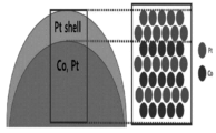
- 1 is a schematic diagram of the catalyst of the present invention.
- Example 3 shows Example (Co 0.2 /Pt 0.8 /C), Comparative Example 1 (commerical Pt/C), Comparative Example 2 (Co 0.25 /Pt 0.75 /C), and Comparative Example 3 (Co 0.5 /Pt 0.5 / This is the XRD result of C).
- Example 4 shows XRD results of Example (Co 0.2 /Pt 0.8 /C) and Comparative Example 2 (Co 0.25 /Pt 0.75 /C).
- Example 5 is an XRD result of Example (Co 0.2 /Pt 0.8 /C) and Comparative Example 2 (Co 0.25 /Pt 0.75 /C).
- Example 9 is a TGA (thermogravimetric analysis) result of Example.
- Example 10 is a linear scanning potential (LSV) evaluation result of Example (Co 0.2 /Pt 0.8 /C) and Comparative Example 1 (Commerical Pt/C).
- Example 11 is a comparison result of onset potentials of Example (Co 0.2 /Pt 0.8 /C) and Comparative Example 1 (Commercial Pt/C).
- Example 13 is a cyclic voltammetry evaluation result of carbon monoxide stripping in Example (Co 0.2 /Pt 0.8 /C).
- Example 14 is a cyclic voltammetry evaluation result of carbon monoxide stripping of Example (Co 0.2 /Pt 0.8 /C) and Comparative Example 1 (Commercial Pt/C).
- Example 15 is an evaluation result of constant voltage durability against formic acid of Example (Co 0.2 /Pt 0.8 /C) and Comparative Example 1 (Commercial Pt/C).
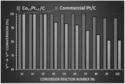
- Example 16 shows durability evaluation results of Example (Co 0.2 /Pt 0.8 /C) and Comparative Example 1 (Commerical Pt/C).
- the temperature and pressure may be room temperature and normal pressure.
- room temperature may mean a temperature in a natural state that is not particularly heated and/or cooled.
- Room temperature may be, for example, a temperature in the range of 20 °C to 30 °C, about 25 °C or about 23 °C.
- normal pressure may mean pressure in a natural state that is not particularly pressurized and/or reduced. Normal pressure may mean, for example, atmospheric pressure of about 1 atm.
- the present invention relates to catalysts.
- the catalyst of the present invention is a trivalent vanadium compound (V (III)) and a tetravalent vanadium compound ( It is used to prepare a vanadium electrolyte containing V(IV)). That is, the present invention relates to a catalyst for preparing a vanadium electrolyte solution.
- the present invention is more suitable for preparing a vanadium electrolyte solution in which a trivalent vanadium compound (V(III)) and a tetravalent vanadium compound (V(IV)) are mixed in a predetermined volume ratio.
- the ratio (V(III):V(IV)) may be 4:6 to 6:4, 4.5:5.5 to 5.5:4.5, 4.9:5.1 to 5.1:4.9, or about 1:1.
- a solution in which a trivalent vanadium compound (V(III)) and a tetravalent vanadium compound (V(IV)) are mixed at a volume ratio (V(III):V(IV)) within the range of 4:6 to 6:4 is called a vanadium electrolyte.
- the reaction to which the catalyst of the present invention is applied is a reduction reaction of a tetravalent vanadium compound as described above.
- the reaction is a reaction between the tetravalent vanadium compound and the reducing agent of the tetravalent vanadium compound, and may proceed in the presence of the catalyst.
- a catalyst in the form of supporting platinum as a single metal on a support or a catalyst in the form of supporting a platinum-based alloy on a support was applied.
- the former has a Pt/C (Pt on carbon) catalyst.
- catalysts using platinum single metal did not have very high activity.
- the platinum-based alloy is mainly an alloy of platinum and a transition metal.
- transition metal ions are eluted from a single metal of a platinum-based alloy.
- the platinum-based catalyst generated carbon monoxide when the aforementioned reducing agent, for example, formic acid was applied. Carbon monoxide causes a decrease in catalyst activity.
- the electrolyte solution for a oxidizing electrode of a vanadium battery according to the present invention includes an intermetallic compound as a catalyst.
- the intermetallic compound may refer to a structure in which a plurality of metal components are regularly arranged. This is different from alloys with randomly placed metals.
- the catalyst for preparing a vanadium electrolyte of the present invention includes an intermetallic compound of a specific metal component.
- the metal components include cobalt and platinum. That is, the catalyst for preparing a vanadium electrolyte of the present invention includes an intermetallic compound of metal components including cobalt and platinum.
- the metal component may further include other metal components in addition to cobalt and platinum.
- the mixing ratio of each metal in the metal component of the intermetallic compound is also controlled.
- the metal component includes cobalt and platinum, and the molar ratio (Pt/Co) of the cobalt (Co) and the platinum (Pt) is greater than 3. In particular, it has a high ratio of platinum compared to conventional platinum-cobalt intermetallic compounds. This is because the reaction to which the catalyst of the present invention is applied occurs in a strongly acidic solution.
- the molar ratio may be greater than 3.5 or greater than 4.0.
- the upper limit of the molar ratio is not particularly limited, but may be appropriately adjusted for electrical activity. In other embodiments, the molar ratio may be 10 or less, 9 or less, 8 or less, 7 or less, 6 or less, 5.5 or less, 5 or less, or 4 or less.
- the catalyst has a core-shell structure.
- the core-shell structure includes the intermetallic compound. That is, the catalyst has a core-shell structure including the intermetallic compound.
- the shell of the core-shell structure may include platinum.
- the intermetallic compound of the present invention has a higher platinum content than conventional intermetallic compounds, which implies that platinum forms a shell in a core-shell structure or that the shell contains platinum.
- the core of the catalyst may include the intermetallic compound.
- the shell of the catalyst may include platinum. Through this, it has excellent corrosion resistance even in a strongly acidic vanadium electrolyte, so that the efficiency of the oxidation reaction of the reducing agent can be increased.
- the catalyst may have a form in which the above-described core-shell structure is supported on a support. That is, the catalyst may further include a support, and the core-shell structure may be supported on the support.
- the type of support is not particularly limited, and a known carbon-based support or the like can be applied.
- the fact that the content of platinum in the intermetallic compound is high indicates that platinum is included in the shell of the core-shell structure formed by the catalyst, and its thickness is thicker than before.
- the thickness of the shell of the core-shell structure may be in the range of 0.6 nm to 1.5 nm.
- the lower limit of the thickness may be 0.7 nm or 0.8 nm.
- the upper limit of the thickness may be 1.4 nm, 1.3 nm or 1.2 nm. This is thicker than the previous one.
- the thickness of the shell in the core-shell structure can be measured through morphology analysis (eg, using high-resolution TEM) of the core-shell structure.
- additional platinum treatment is required, but this is not suitable when considering process economy.
- the intermetallic compound used in the present invention may have a specific structure. Specifically, the intermetallic compound may have a specific crystal structure. In one embodiment, the intermetallic compound may have a face-centered cubic structure. Also, the intermetallic compound may have an L1 2 configuration. Specifically, the intermetallic compound may have a face-centered cubic structure in which cobalt penetrates a lattice formed by platinum, and may have an L1 2 arrangement at the same time. That is, in one embodiment, the intermetallic compound has an L1 2 type face-centered cubic structure. The structure means that cobalt and platinum are regularly arranged.
- the d orbital of cobalt, a transition metal, and the d orbital of platinum, a noble metal overlap each other, and catalytic activity can be maximized due to this structural uniformity.
- the catalyst applied in the present invention may exhibit unique crystal characteristics.
- the characteristics of crystals can be confirmed by X-ray diffraction (XRD) analysis.
- XRD analysis is performed on the catalyst applied in the present invention, several unique features can be identified.
- the catalyst may exhibit two peaks at 2 ⁇ within the range of 39.8 degrees to 46.7 degrees upon XRD analysis.
- any one of the two peaks may be a peak in the (111) direction appearing at 2 ⁇ within the range of 39.8 degrees to 40 degrees.
- the other peak of the two peaks may be a peak in the (200) direction appearing at 2 ⁇ within the range of 46 degrees to 46.7 degrees.
- the catalyst may exhibit two peaks at 2 ⁇ within the range of 67 degrees to 82.2 degrees upon XRD analysis.
- any one of the two peaks may be a peak in the (220) direction appearing at 2 ⁇ within the range of 67 degrees to 68 degrees.
- the other one of the two peaks may be a peak in the (311) direction appearing at 2 ⁇ within the range of 81 degrees to 82.2 degrees.
- the catalyst of the present invention is suitable for preparing a vanadium electrolyte.
- the intermetallic compound of the catalyst of the present invention may be known, but it is not an easy attempt to use a catalyst having such an intermetallic compound for preparing a vanadium electrolyte.
- the content of platinum is higher than before. Therefore, the catalyst can act stably in an acidic vanadium electrolyte precursor solution, but no such attempt has been made in the past.
- the present invention relates to a method for preparing a vanadium electrolyte solution.
- the vanadium electrolyte solution has a volume ratio (V(III): V(IV)) may mean a mixed solution.
- the vanadium electrolyte is prepared by reacting a tetravalent vanadium compound with a reducing agent of the tetravalent vanadium compound. Also, the reaction proceeds in the presence of a catalyst.
- the catalyst applied here is the catalyst of the present invention.
- the method for preparing a vanadium electrolyte of the present invention reacts a raw material including a tetravalent vanadium compound and a reducing agent for the tetravalent vanadium compound in the presence of a catalyst to obtain a tetravalent vanadium compound (V(IV)) and a trivalent vanadium compound ( V(III)) in a volume ratio (V(IV):V(III)) within the range of 4:6 to 6:4; preparing a product.
- the reducing agent of the tetravalent vanadium compound may be an organic material.
- the reducing agent for the tetravalent vanadium compound may be at least one of formic acid, formaldehyde, methanol, oxalic acid, and ammonium hydroxide.
- oxalic acid or formic acid is used as a reducing agent, which is an acidic substance, so that the catalyst of the present invention can act more significantly.
- the content of the catalyst may be in the range of 1 mg to 8 mg per 1 mL of the raw material.
- the reaction ratio of the reactants is also very important to achieve the desired product yield.
- the molar ratio (R/V(IV)) of the tetravalent vanadium compound (V(IV)) and the reducing agent (R) in the raw material may be in the range of 0.1 to 0.5.
- the system in which the reaction proceeds may exhibit acidity.
- the catalyst of the present invention can stably promote the reaction here.
- the raw material may further include a strong acid solution, specifically, a sulfuric acid aqueous solution.
- the raw material may contain a significant amount of the sulfuric acid aqueous solution. Accordingly, the concentration of the aqueous sulfuric acid solution may be 4 M or more.
- the reaction raw material to which the catalyst acts may be prepared through a reduction reaction of vanadium pentoxide. That is, when a raw material containing vanadium pentoxide, a reducing agent for vanadium pentoxide, and sulfuric acid is reacted, a product solution containing tetravalent vanadium ions and sulfuric acid can be prepared.
- the vanadium pentoxide reducing agent and the tetravalent vanadium ion reducing agent may be the same component or may be different components. Since it is usually a different reduction reaction, other reducing agents can be applied. Meanwhile, the reducing agent for the vanadium pentoxide may be those listed as reducing agents for the above-described tetravalent vanadium compound, and among them, may be selected differently from the reducing agent for the tetravalent vanadium compound. For example, a reducing agent for vanadium pentoxide may be oxalic acid, and a reducing agent for a tetravalent vanadium compound may be formic acid. Since the reduction reaction of vanadium pentoxide is a known technique, a detailed description thereof is omitted in the present invention.
- Separation of the catalyst after production of the product, separation and purification of the product, and the like may be performed in a known manner.
- the crystal structure of the catalyst was determined through XRD analysis.
- XRD analysis PANalyti cal's EMPYREAN product was used, and the analysis was conducted according to the equipment manual.
- composition and morphology of the catalyst were analyzed using HR-TEM and its accompanying EDS mapping and line scanning functions.
- HR-TEM JEOL's JEM-2200FS (with image Cs-corrector) product was used, and analysis was performed according to the manual of the equipment.
- a catalyst/support composite was prepared so that the target supported amount of the catalyst prepared in Example was 40% by weight.
- the supported amount of the catalyst in the composite was measured by TGA.
- TA instrument's TGA 2950 was used as the TGA equipment, and the analysis was conducted according to the manual of the equipment.
- LSV evaluation was performed to confirm the activity of the catalyst for the formic acid oxidation reaction.
- an evaluation of the durability of the constant voltage against formic acid was performed.
- the evaluation was conducted using a three-electrode system.
- the three electrodes were Ag/AgCl (3M NaCl), Pt wire, and glassy carbon as a reference electrode, a counter electrode, and a working electrode, respectively.
- Voltage and current curves were obtained using the Nova Soft program from three electrodes connected to Metrohm's Autolab equipment.
- An electrolyte solution was prepared by mixing 0.25 M sulfuric acid aqueous solution and 0.5 M formic acid aqueous solution in a volume ratio of 50:50.
- the catalyst to be evaluated was slurried and supported on the working electrode in an amount of 15 ⁇ l.
- Catalyst slurry was prepared by mixing 8 mg of catalyst, 3.18 mL of deionized water, 0.8 mL of 2-propanol (Aldrich), and 20 ⁇ l of Nafion solution (20% w/w water solution, Dupont).
- LSV was conducted in the potential range of the formic acid oxidation reaction (-0.1 V to 1.2 V, based on Ag/AgCl), 20 mV/s, and room temperature. Onset potentials are also evaluated in this experiment.
- the evaluation was conducted using a three-electrode system.
- the three electrodes were Ag/AgCl (3M NaCl), Pt wire, and glassy carbon as a reference electrode, a counter electrode, and a working electrode, respectively.
- Voltage and current curves were obtained using the Nova Soft program from three electrodes connected to Metrohm's Autolab equipment.
- Catalyst slurry was prepared by mixing 8 mg of catalyst, 3.18 mL of deionized water, 0.8 mL of 2-propanol (Aldrich), and 20 ⁇ l of Nafion solution (20% w/w water solution, Dupont).
- Cyclocurrent was performed before and after 30 minutes of CO gas exposure. Specifically, CO gas was injected into the sulfuric acid electrolyte containing the three electrodes for 30 minutes. This is to confirm the electrochemical behavior of the catalyst by arbitrarily adsorbing CO on the catalyst. After CO gas exposure, the CO gas input line was removed from the electrolyte containing the three-electrode system, and CO stripping voltammetry was performed. Performance evaluation was conducted within the potential range (-0.1 V to 1.0 V, based on Ag/AgCl) in which the CO oxidation-reduction reaction of the catalyst occurs. The evaluation conditions were 20 mV/s and room temperature.
- the evaluation was conducted using a three-electrode system.
- the three electrodes were Ag/AgCl (3M NaCl), Pt wire, and glassy carbon as a reference electrode, a counter electrode, and a working electrode, respectively.
- Voltage and current curves were obtained using the Nova Soft program from three electrodes connected to Metrohm's Autolab equipment.
- An electrolyte solution was prepared by mixing 0.25 M sulfuric acid aqueous solution and 0.5 M formic acid aqueous solution in a volume ratio of 50:50.
- the catalyst to be evaluated was slurried and supported on the working electrode in an amount of 15 ⁇ l.
- Catalyst slurry was prepared by mixing 8 mg of catalyst, 3.18 mL of deionized water, 0.8 mL of 2-propanol (Aldrich), and 20 ⁇ l of Nafion solution (20% w/w water solution, Dupont).
- the carbon substrate is doped with nitrogen and electrical bonding between the doped nitrogen and the metal precursor is induced, aggregation between metal particles can be prevented and an appropriate intermetallic compound can be formed.
- Nitrogen doping was performed in the following order.
- the blended urea and carbon supports were heat treated under an atmosphere in which nitrogen gas was continuously flowing. Specifically, after heating to 150°C at a heating rate of 2°C/min and holding for 2 hours, heating to 300°C at a heating rate of 5°C/min and holding for 2 hours.
- Nitrogen doping on the carbon substrate was confirmed by XPS analysis.
- 2 is an XPS result of a preparation example. At the binding energy of 289 eV, sp 3 carbon-oxygen and carbon-nitrogen bonds were confirmed. In addition, the nitrogen of pyridine was confirmed at the binding energy point of 389 eV. This means that the carbon support was successfully doped with nitrogen.
- the catalyst was prepared by Softnitriding technique.
- the molar ratio of the cobalt precursor to the platinum precursor was 1:3.
- the catalyst of Comparative Example 2 was expressed as Co 0.25 /Pt 0.75 /C.
- a catalyst was prepared in the same manner as in Comparative Example 2, except that the molar ratio of the cobalt precursor and the platinum precursor (cobalt precursor:platinum precursor) was changed to 1:1.
- the catalyst of Comparative Example 2 was expressed as Co 0.5 /Pt 0.5 /C.
- Example 3 shows Example (Co 0.2 /Pt 0.8 /C), Comparative Example 1 (commerical Pt/C), Comparative Example 2 (Co 0.25 /Pt 0.75 /C), and Comparative Example 3 (Co 0.5 /Pt 0.5 / This is the XRD result of C).
- 4 shows XRD results of Example (Co 0.2 /Pt 0.8 /C) and Comparative Example 2 (Co 0.25 /Pt 0.75 /C).
- 5 is an XRD result of Example (Co 0.2 /Pt 0.8 /C) and Comparative Example 2 (Co 0.25 /Pt 0.75 /C).
- cobalt was additionally introduced in the catalyst of Comparative Example 1, crystal peaks in (111) and (200) directions shifted to the right.
- cobalt was additionally introduced in the catalyst of Comparative Example 1, it was confirmed that a unique lattice structure appeared only in intermetallic compounds having regular atomic arrangements.
- the thickness of Pt corresponding to the shell of the core-shell structure may be greater in Example 1 than in Comparative Example 2.
- the catalyst can have excellent durability even in an acidic environment such as a vanadium electrolyte manufacturing environment. Through this, it can be seen that the amount of cobalt introduced must be appropriately controlled.
- the catalyst of the present invention includes an intermetallic compound having a face-centered cubic structure with a (110) direction d-spacing of 0.27 nm. It can be seen from FIG. 7 that the catalyst of the present invention is an intermetallic compound of platinum and cobalt. It can be seen from FIG. 8 that the catalyst of the present invention has a core-shell structure having a core composed of an intermetallic compound of platinum and cobalt and a shell composed of platinum, and at this time, it can be confirmed that the thickness of the shell is in the range of 0.8 nm to 1.2 nm. can This is much thicker (at least 160%) than the intermetallic thickness (0.5 nm) used in the existing literature.
- Example 9 is a TGA result confirming how much the catalyst of Example (Co 0.2 /Pt 0.8 /C) is supported on the carbon support.
- the target loading amount of the catalyst in Example was 40% by weight.
- thermogravimetric analysis it can be confirmed that 37% by weight of the catalyst of the examples was supported on the carbon support.
- Example 10 is an LSV evaluation result for the catalyst of Example (Co 0.2 /Pt 0.8 /C) and Comparative Example 1 (commerical Pt/C). It can be confirmed that the catalysts of Examples are superior to the catalysts of Comparative Examples in formic acid oxidizing ability. Specifically, when comparing the amount of current generated at 0.6 V, which is the maximum electrochemical oxidation voltage, it can be seen that Example has about twice as much current as Comparative Example 1.
- FIG. 11 compares formic acid oxidation onset potentials of Example (Co 0.2 /Pt 0.8 /C) and Comparative Example 1 (commerical Pt/C) based on the LSV evaluation results.
- Example Co 0.2 /Pt 0.8 /C
- Comparative Example 1 Commerical Pt/C
- Example 15 is an evaluation result of constant voltage durability against formic acid of Example (Co 0.2 /Pt 0.8 /C) and Comparative Example 1 (Commercial Pt/C). It can be seen that the catalyst of Comparative Example 1 shows a rapid performance decrease. It can be seen that the performance of the catalysts of the examples is maintained almost constant. This means that the catalysts of the examples have excellent durability against acid as well as durability against CO poisoning.
- Example 16 shows durability evaluation results of Example (Co 0.2 /Pt 0.8 /C) and Comparative Example 1 (Commerical Pt/C). It can be seen that when the catalyst of Comparative Example 1 was applied, the conversion rate to the vanadium electrolyte decreased as the number of conversion reactions increased. In the case of applying the catalyst of the examples, it can be seen that the conversion rate to the vanadium electrolyte does not decrease significantly even if the number of conversion reactions increases, but shows a slight decrease only when the number of conversion reactions reaches 80 times.
- the catalysts of Examples have high catalytic activity according to the regular atomic arrangement of the intermetallic compound and have a core-shell structure that can have acid resistance, so V (III / IV) conversion rate and durability compared to the catalyst of Comparative Example 1 You can see this excellence.
Landscapes
- Chemical & Material Sciences (AREA)
- Organic Chemistry (AREA)
- Engineering & Computer Science (AREA)
- Chemical Kinetics & Catalysis (AREA)
- Materials Engineering (AREA)
- Manufacturing & Machinery (AREA)
- Life Sciences & Earth Sciences (AREA)
- Sustainable Development (AREA)
- Sustainable Energy (AREA)
- Electrochemistry (AREA)
- General Chemical & Material Sciences (AREA)
- Inorganic Chemistry (AREA)
- Catalysts (AREA)
Abstract
본 발명은 바나듐 전해액 제조용 촉매 및 바나듐 전해액의 제조 방법에 관한다. 본 발명은 바나듐 전해액을 보다 빠르게 제조할 수 있다. 본 발명은 바나듐 전해액을 보다 효율적으로 제조할 수 있다. 본 발명은 바나듐 전해액을 보다 안정적으로 제조할 수 있다.
Description
본 발명은 바나듐 전해액 제조용 촉매에 관한다.
본 발명은 바나듐 전해액 제조 방법에 관한다.
본 발명의 바나듐 전해액 제조 방법은 본 발명의 바나듐 전해액 제조용 촉매를 사용하는 것이다.
바나듐을 이용하는 배터리에 대해 많은 연구가 진행되고 있다. 바나듐을 이용하는 배터리에는 바나듐 이온 배터리, 바나듐 레독스 흐름 배터리 등이 있다. 본 배터리에 사용되는 전해액은 4 가 바나듐 화합물(V(IV))을 포함하는 전해액이다. 해당 전해액을 바나듐 배터리에 사용하는 경우, 충전 시 V(IV)의 V(V)로의 산화 반응이 일어나는 양극과 V(IV)의 V(II)로의 환원 반응(V(IV)의 V(III)로의 환원 후, V(III)의 V(II)로의 환원 진행)이 일어나는 음극 각각에 필요한 전해액의 양이 달라진다. 따라서, 양 전극에 필요한 전해액의 비율을 맞추기 위해서, 바나듐 전해액은 V(III/IV) 형태로 전환되어 유통된다. V(III/IV)는 3 가 바나듐 화합물(V(III))과 4 가 바나듐 화합물(V(IV))이 약 1:1의 부피 비로 혼합된 용액이다. 이하, 3 가 바나듐 화합물(V(III))과 4 가 바나듐 화합물(V(IV))이 4:6 내지 6:4 범위 내의 부피 비로 혼합된 용액을 바나듐 전해액이라고 한다.
3.5 가 바나듐 전해액을 얻는 방법으로는, (1) 4 가 전해액에 환원제를 투입하는 화학적 환원법과, (2) 전지 구동으로 환원 전극에서 4 가 전해액을 환원하는 방법 등이 있다. 전자는 빠르게 진행할 수 있지만, 환원제가 전해액에 잔류하는 문제가 있다. 후자는 배터리 구동에 비용과 시간이 소요되고, 산화수(3.5)를 정확히 맞추기 위해 충전량을 세밀히 조절해야 하는 문제가 있다.
특허문헌 1과 같이 귀금속을 이용한 촉매(Pt/C, 탄소 담지체에 Pt가 담지된 형태)를 사용해서, 바나듐 전해액을 제조하는 방법이 알려졌다. 해당 방법에서, Pt/C 촉매와 포름산(환원제)은 자발적 반응으로 전자를 방출하며, 그 전자가 4 가 전해액의 일부를 환원시켜서 바나듐 전해액을 제조하는 것을 기본 원리로 한다. 해당 방식은 기존 방식 대비 간단하고, 전해액 생산성이 높다.
그러나, 특허문헌 1의 방법에 따르면 촉매가 포름산을 산화하는 과정에서 일산화탄소가 발생한다. 일산화탄소는 촉매 활성 저하의 원인인 피독 현상을 유발한다. 또한, Pt/C 촉매는 Pt계 합금을 적용한 촉매 대비 활성이 너무 떨어진다.
[선행기술문헌]
[특허문헌]
(특허문헌 1) 등록특허공보 제10-2238667호
본 발명에서는 바나듐 전해액을 보다 빠르게 제조하고자 한다.
본 발명에서는 바나듐 전해액을 보다 효율적으로 제조하고자 한다.
본 발명에서는 바나듐 전해액을 보다 안정적으로 제조하고자 한다.
본 발명의 바나듐 전해액 제조용 촉매는 코발트 및 백금을 포함하는 금속 성분의 금속간화합물(intermetallic compound)을 포함하는 코어-쉘 구조를 가지고, 상기 코발트(Co)와 상기 백금(Pt)의 몰 비(Pt/Co)는 3 초과인 것이다.
본 발명의 바나듐 전해액의 제조 방법은 4 가 바나듐 화합물 및 상기 4 가 바나듐 화합물의 환원제를 포함하는 원료를 촉매의 존재 하에 반응시켜서, 4 가 바나듐 화합물(V(IV)) 및 3가 바나듐 화합물(V(III))을 4:6 내지 6:4 범위 내의 부피 비율(V(IV):V(III))로 포함하는 생성물을 제조하는 단계;를 포함하고, 상기 촉매는 본 발명의 바나듐 전해액 제조용 촉매인 것이다.
본 발명은 바나듐 전해액을 보다 빠르게 제조할 수 있다.
본 발명은 바나듐 전해액을 보다 효율적으로 제조할 수 있다.
본 발명은 바나듐 전해액을 보다 안정적으로 제조할 수 있다.
도 1은 본 발명의 촉매의 모식도다.
도 2는 제조예의 XPS 결과다.
도 3은 실시예(Co0.2/Pt0.8/C), 비교예 1(commerical Pt/C), 비교예 2(Co0.25/Pt0.75/C) 및 비교예 3(Co0. 5/Pt0.5/C)의 XRD 결과다.
도 4는 실시예(Co0.2/Pt0.8/C) 및 비교예 2(Co0.25/Pt0.75/C)의 XRD 결과다.
도5는 실시예(Co0.2/Pt0.8/C) 및 비교예 2(Co0.25/Pt0.75/C)의 XRD 결과다.
도 6은 실시예의 HR-TEM 분석 결과다.
도 7은 실시예의 HR-TEM 분석 결과다.
도 8은 실시예의 line scan 분석 결과다.
도 9는 실시예의 TGA(열중량 분석) 결과다.
도 10은 실시예(Co0.2/Pt0.8/C) 및 비교예 1(Commerical Pt/C)의 선형주사전위법(LSV) 평가 결과다.
도 11은 실시예(Co0.2/Pt0.8/C) 및 비교예 1(Commerical Pt/C)의 개시 전위(Onset Potential) 비교 결과다.
도 12는 비교예 1(Commerical Pt/C)의 일산화탄소 스트리핑의 순환전압 전류법 평가 결과다.
도 13은 실시예(Co0.2/Pt0.8/C)의 일산화탄소 스트리핑의 순환전압 전류법 평가 결과다.
도 14는 실시예(Co0.2/Pt0.8/C) 및 비교예 1(Commercial Pt/C)의 일산화탄소 스트리핑의 순환전압 전류법 평가 결과다.
도 15는 실시예(Co0.2/Pt0.8/C) 및 비교예 1(Commercial Pt/C)의 포름산에 대한 정전압 내구성 평가 결과다.
도 16은 실시예(Co0.2/Pt0.8/C) 및 비교예 1(Commerical Pt/C)의 내구성 평가 결과다.
본 명세서에서, 온도와 압력이 특정 물성에 영향을 준다면, 그 온도와 압력은 상온 및 상압일 수 있다.
본 명세서에서, 상온은, 특별히 가온 및/또는 감온하지 않은 자연 상태 그대로의 온도를 의미할 수 있다. 상온은, 예를 들어, 20 ℃ 내지 30 ℃ 범위 내의 온도, 약 25 ℃ 또는 약 23 ℃일 수 있다.
본 명세서에서, 상압은, 특별히 가압 및/또는 감압하지 않은 자연 상태 그대로의 압력을 의미할 수 있다. 상압은, 예를 들어 대기압인 약 1 기압을 의미할 수 있다.
본 발명은 촉매에 관한다. 특히 본 발명의 촉매는 4 가 바나듐 화합물(V(IV)) 일부의 3 가 바나듐 화합물(V(III))으로의 환원을 통해, 3 가 바나듐 화합물(V(III))과 4 가 바나듐 화합물(V(IV))을 포함하는 바나듐 전해액을 제조하는데 사용된다. 즉, 본 발명은 바나듐 전해액 제조용 촉매에 관한다.
특히 본 발명은, 3 가 바나듐 화합물(V(III))과 4 가 바나듐 화합물(V(IV))이 소정의 부피 비로 혼합된 용액인 바나듐 전해액 제조에 더욱 적합하다. 상기 비율(V(III):V(IV))은 4:6 내지 6:4, 4.5:5.5 내지 5.5:4.5, 4.9:5.1 내지 5.1:4.9 또는 약 1:1일 수 있다. 이하, 3 가 바나듐 화합물(V(III))과 4 가 바나듐 화합물(V(IV))이 4:6 내지 6:4 범위 내의 부피 비(V(III):V(IV))로 혼합된 용액을 바나듐 전해액이라고 한다.
본 발명의 촉매가 적용되는 반응은, 전술한 것처럼 4 가 바나듐 화합물의 환원 반응이다. 상기 반응은 상기 4 가 바나듐 화합물과, 상기 4 가 바나듐 화합물의 환원제의 반응으로, 상기 촉매의 존재 하에 진행될 수 있다.
이와 같은 반응의 촉매로는 단일 금속으로 백금을 담지체에 담지한 형태의 촉매 또는 백금계 합금을 담지체에 담지한 형태의 촉매를 적용했다. 전자에는 Pt/C(Pt on carbon) 촉매가 있다. 그러나, 백금 단일 금속을 적용한 촉매는 활성도가 그다지 높지 않았다. 후자에서 백금계 합금은, 주로 백금과 전이 금속의 합금이다. 또한, 대체로 강산성을 띄는 바나듐 전해액에서, 백금계 합금 단일 금속은 전이 금속 이온이 용출된다. 그리고 백금계 촉매는 전술한 환원제, 예를 들어 포름산을 적용한 경우 일산화 탄소를 발생시켰다. 일산화탄소는 촉매 활성도 저하의 원인이다.
이 점을 해결하기 위해 본 발명의 바나듐 전지 산화 전극용 전해액은 촉매로 금속간화합물을 포함한다. 금속간화합물은 복수의 금속 성분이 규칙적으로 배열된 구조체를 의미할 수 있다. 이는 무작위로 배치된 금속을 가지는 합금과는 다르다.
본 발명의 바나듐 전해액 제조용 촉매는 특정 금속 성분의 금속간화합물을 포함한다. 상기 금속 성분은 코발트 및 백금을 포함한다. 즉, 본 발명의 바나듐 전해액 제조용 촉매는 코발트 및 백금을 포함하는 금속 성분의 금속간화합물을 포함한다. 상기 금속 성분은 코발트 및 백금 외에도 다른 금속 성분을 추가로 포함할 수도 있다.
본 발명의 바나듐 전해액 제조용 촉매에서 금속간화합물의 금속 성분에서 각 금속의 혼합 비율 또한 조절된다. 금속 성분은 코발트와 백금을 포함하고, 상기 코발트(Co)와 상기 백금(Pt)의 몰 비(Pt/Co)는 3 초과다. 특히 이는 기존의 백금-코발트 금속간 화합물 대비 백금의 비율이 높다. 본 발명의 촉매가 적용되는 반응이 강산성 용액에서 일어나기 때문이다.
일 구현예에서, 상기 몰 비는 3.5 이상 또는 4.0 이상일 수 있다. 상기 몰 비의 상한은 특별히 제한은 없지만 전기적 활성을 위해 적절히 조절되는 것이 좋다. 다른 구현예에서, 상기 몰 비는 10 이하, 9 이하, 8 이하, 7 이하, 6 이하, 5.5 이하, 5 이하 또는 4 이하일 수 있다.
본 발명에서는 특정 형태의 촉매를 사용한다. 구체적으로, 전술한 강산에 대한 내구성을 확보하는 측면에서 소정의 구조를 가져서 강산으로부터 촉매의 활성 물질을 보호해야 한다. 상기 촉매는 코어-쉘(core-shell) 구조를 가진다. 구체적으로, 상기 코어-쉘 구조는 상기 금속간화합물을 포함한다. 즉 상기 촉매는 상기 금속간화합물을 포함하는 코어-쉘 구조를 가진다.
일 구현예에서, 상기 코어-쉘 구조의 쉘은 백금을 포함할 수 있다. 위에서 언급한 것처럼 본 발명의 금속간화합물은 기존의 금속간화합물 대비 백금의 함량이 높은데 이는 백금이 코어-쉘 구조에서 쉘을 형성하거나, 혹은 쉘이 백금을 포함하는 점을 암시하는 것이다.
도 1은 본 발명의 촉매의 모식도다. 여기서 확인할 수 있는 것처럼, 상기 촉매의 코어가 상기 금속간 화합물을 포함할 수 있다. 또한 상기 촉매의 쉘이 백금을 포함할 수 있다. 이를 통해 강산성인 바나듐 전해액에서도 우수한 내식성을 가져서 환원제의 산화 반응의 효율을 높일 수 있다.
또한 상기 촉매는, 전술한 코어-쉘 구조가 담지체에 담지된 형태를 가질 수 있다. 즉 상기 촉매는 담지체를 추가로 포함할 수 있고, 상기 코어-쉘 구조가 상기 담지체에 담지될 수 있다. 담지체의 종류는 특별히 제한되지 않고, 공지의 탄소계 지지체 등을 적용할 수 있다.
또한, 상기 금속간화합물에서 백금의 함량이 높다는 것은 상기 촉매가 형성하는 코어-쉘 구조의 쉘에 백금이 포함되면서, 이의 두께가 기존 대비 두껍다는 것도 알 수 있다. 일 구현예에서, 상기 코어-쉘 구조의 쉘의 두께는 0.6 nm 내지 1.5 nm 범위 내일 수 있다. 다른 구현예에서, 상기 두께의 하한은, 0.7 nm 또는 0.8 nm일 수 있다. 다른 구현예에서, 상기 두께의 상한은, 1.4 nm, 1.3 nm 또는 1.2 nm일 수 있다. 이는 기존의 것 대비 두꺼운 수치다. 또한 상기 코어-쉘 구조에서 쉘의 두께는 상기 코어-쉘 구조의 모폴로지 분석(예를 들어, 고해상도 TEM 사용 등)을 통해 측정할 수 있다. 또한 쉘의 두께를 상기 범위의 상한 보다 높게 하려면, 추가의 백금 처리가 필요하나, 이는 공정 경제를 고려했을 때 적합하지 않다.
본 발명에서 적용한 금속간화합물은 특정 구조를 가질 수 있다. 구체적으로, 상기 금속간화합물은 특정 결정 구조를 가질 수 있다. 일 구현예에서, 상기 금속간화합물은 면심 입방 구조를 가질 수 있다. 또한 상기 금속간화합물은 L12 배열을 가질 수 있다. 구체적으로, 상기 금속간화합물은 백금이 형성한 격자에 코발트가 침투한 형태의 면심 입방 구조를 가질 수 있으며, 동시에 L12 배열을 가질 수 있다. 즉, 일 구현예에서, 상기 금속간화합물은 L12 형 면심 입방 구조를 가지는 것이다. 해당 구조는 코발트와 백금이 규칙적으로 배치되어 있음을 의미한다. 구체적으로 본 발명에서 사용한 금속간화합물에서 전이금속인 코발트의 d 오비탈과 귀금속인 백금의 d 오비탈이 중첩되어 존재하는데, 이러한 구조적 균일성 때문에 촉매 활성을 극대화할 수 있다.
또한 본 발명에서 적용하는 촉매는 특이한 결정 특성을 나타낼 수 있다. 보통 결정의 특성은 X선 회절(XRD) 분석을 통해 확인할 수 있다. 본 발명에서 적용한 촉매에 XRD 분석을 진행하면 몇 가지 독특한 모습을 확인할 수 있다.
일 구현예에서, 상기 촉매는 XRD 분석 시, 39.8 도 내지 46.7 도 범위 내의 2Θ에서 2 개의 피크를 나타낼 수 있다.
구체적으로, 상기 2 개의 피크 중 어느 하나의 피크는 39.8 도 내지 40 도 범위 내의 2Θ에서 나타나는 (111) 방향의 피크일 수 있다. 또한, 상기 2 개의 피크 중 나머지 하나의 피크는 46 도 내지 46.7 도 범위 내의 2Θ에서 나타나는 (200) 방향의 피크일 수 있다.
추가로, 상기 촉매는 XRD 분석 시, 67 도 내지 82.2 도 범위 내의 2Θ에서 2개의 피크를 나타낼 수 있다.
구체적으로, 상기 2 개의 피크 중 어느 하나의 피크는 67 도 내지 68 도 범위 내의 2Θ에서 나타나는 (220) 방향의 피크일 수 있다. 또한, 상기 2 개의 피크 중 나머지 하나의 피크는 81 도 내지 82.2 도 범위 내의 2Θ에서 나타나는 (311) 방향의 피크일 수 있다.
이는 후술하는 실시예에서도 확인하겠지만, 기존의 백금계 촉매 혹은 다른 금속간화합물 촉매에서는 확인되지 않는 본 발명 촉매의 고유 특성이다. 이는 곧 본 발명의 촉매가 바나듐 전해액 제조에 적합하다는 것을 의미한다. 본 발명의 촉매가 갖는 금속간화합물은 알려진 것일 수 있으나, 이러한 금속간화합물을 갖는 촉매를 바나듐 전해액의 제조에 사용하는 것은 결코 쉬운 시도가 아니다. 특히 해당 촉매의 경우 기존 대비 백금의 함량이 높다. 따라서 상기 촉매는 산성을 나타내는 바나듐 전해액 전구체 용액에서 안정적으로 작용할 수 있는데, 기존엔 이런 시도가 전혀 없었다.
본 발명은 다른 측면에서, 바나듐 전해액의 제조 방법에 관한다.
상기 바나듐 전해액은, 전술한 것처럼, 이하, 3 가 바나듐 화합물(V(III))과 4 가 바나듐 화합물(V(IV))이 4:6 내지 6:4 범위 내의 부피 비(V(III):V(IV))로 혼합된 용액을 의미할 수 있다.
상기 바나듐 전해액의 제조는 4 가 바나듐 화합물과 상기 4 가 바나듐 화합물의 환원제의 반응으로 제조된다. 또한 상기 반응은 촉매의 존재 하에 진행된다. 여기서 적용되는 촉매는 본 발명의 촉매다.
즉 본 발명의 바나듐 전해액 제조 방법은, 4 가 바나듐 화합물 및 상기 4 가 바나듐 화합물의 환원제를 포함하는 원료를 촉매의 존재 하에 반응시켜서, 4가 바나듐 화합물(V(IV)) 및 3가 바나듐 화합물(V(III))을 4:6 내지 6:4 범위 내의 부피 비율(V(IV):V(III))로 포함하는 생성물을 제조하는 단계;를 포함한다.
일 구현예에서, 상기 4 가 바나듐 화합물의 환원제는 유기물일 수 있다. 구체적으로, 상기 4가 바나듐 화합물의 환원제는 포름산, 포름 알데히드, 메탄올, 옥살산 및 암모늄 하이드록사이드 중 적어도 하나일 수 있다. 보통은 옥살산 또는 포름산 등을 환원제로 사용하는데, 이는 산성 물질이어서, 본 발명의 촉매가 더욱 유의미하게 작용할 수 있다.
촉매 적용에 따른 적절한 반응 시간을 확보하고, 과투입으로 인한 비용 상승을 방지하는 관점에서, 촉매의 함량 또한 적절히 조절하는 것이 좋다. 일 구현예에서, 상기 촉매의 함량은 상기 원료 1 mL 당 1 mg 내지 8 mg 범위 내일 수 있다.
본 발명에서 진행하는 반응에 있어서, 반응물의 반응 비율도 목적 생성물 수율 달성을 위해선 매우 중요하다. 일 구현예에서, 상기 원료에서 상기 4가 바나듐 화합물(V(IV))과 상기 환원제(R)의 몰 비(R/V(IV))는 0.1 내지 0.5 범위 내일 수 있다.
일 구현예에서, 상기 반응이 진행되는 시스템은 산성을 나타낼 수 있다. 본 발명의 촉매는 여기서 안정적으로 반응을 촉진할 수 있다. 구체적으로, 상기 원료는 강산 용액, 구체적으로 황산 수용액을 더 포함할 수 있다. 또한, 상기 원료에는 상기 황산 수용액이 상당량 포함돼 있을 수 있다. 따라서, 상기 황산 수용액의 농도는 4 M 이상일 수 있다.
한편 상기 촉매가 작용하는 반응 원료는 오산화 바나듐의 환원 반응을 통해 제조된 것일 수 있다. 즉, 오산화 바나듐, 오산화 바나듐의 환원제 및 황산을 포함하는 원료를 반응시키면, 4 가 바나듐 이온 및 황산을 포함하는 생성물 용액이 제조될 수 있다.
상기 오산화 바나듐의 환원제와 4 가 바나듐 이온의 환원제는 동일한 성분일 수도 있고, 다른 성분일 수도 있다. 보통은 다른 환원 반응이기 때문에, 다른 환원제를 적용할 수 있다. 한편, 상기 오산화 바나듐의 환원제는 전술한 상기 4 가 바나듐 화합물의 환원제로 나열한 것일 수 있으며, 이들 중에서 상기 4 가 바나듐 화합물의 환원제와 다르게 선택되는 것일 수 있다. 예를 들어, 오산화 바나듐의 환원제는 옥살산일 수 있고, 4가 바나듐 화합물의 환원제는 포름산일 수 있다. 오산화 바나듐의 환원 반응은 이미 알려진 기술이기 때문에, 본 발명에선 이의 상세한 설명은 생략한다.
상기 생성물 제조 이후의 촉매의 분리, 생성물 분리 및 정제 과정 등은 공지의 방식으로 진행될 수 있다.
이하, 실시예로 본 발명을 보다 상세히 설명한다. 그러나, 하기 실시예는 본 발명의 범위를 제한하지 않는다.
[실험예 1] 질소 도핑 확인
제조예에서 탄소 지지체 상에 질소가 도핑됐는지 여부는 X선 광전자 분석(XPS)으로 진행했다. XPS 분석은 Thermo사의 K-alpha+ 제품을 사용했고, 해당 장비의 매뉴얼에 따라 분석을 진행했다.
[실험예 2] 촉매 결정 구조
촉매의 결정 구조는 XRD 분석을 통해 진행했다. XRD 분석은 PANalyti cal사의 EMPYREAN 제품을 사용했고, 해당 장비의 매뉴얼에 따라 분석을 진행했다.
[실험예 3] 촉매 조성 및 형태
촉매의 조성 및 형태는 HR-TEM과 이에 부속된 EDS mapping 및 line scanning 기능을 활용하여 분석했다. HR-TEM은 JEOL사의 JEM-2200FS(with image Cs-corrector) 제품을 사용했고, 해당 장비의 매뉴얼에 따라 분석을 진행했다.
[실험예 4] 탄소 지지체 상의 촉매 담지량
비교예 1과 동등 수준 비교를 위해, 실시예에서 제조한 촉매의 목표 담지량이 40 중량%가 되도록 촉매/담지체 복합체를 제조했다. 해당 복합체에서 촉매의 담지량은 TGA로 측정했다. TGA 장비로는 TA instrument사의 TGA 2950 제품을 사용했고, 해당 장비의 매뉴얼에 따라 분석을 진행했다.
[실험예 5] 포름산 산화 LSV 평가
LSV 평가를 진행하여 포름산 산화 반응에 대한 촉매의 활성을 확인했다. 또한 여기서 촉매의 내구성 확인을 위해, 포름산에 대한 정전압 내구성 평가를 진행했다.
평가는 3 전극 시스템을 이용하여 진행됐다. 여기서 3 전극은, 기준 전극, 상대전극 및 작업 전극으로서 각각 Ag/AgCl(3M NaCl), Pt wire 및 Glassy carbon였다. Metrohm사의 Autolab 장비에 연결된 3 전극에서 Nova Soft 프로그램을 이용하여 전압, 전류 곡선을 얻었다.
0.25 M 황산 수용액과 0.5 M 포름산 수용액을 50:50의 부피 비율로 혼합하여 전해액을 제조했다. 평가 대상 촉매는 슬러리화하여 작업 전극에 15 ㎕ 담지했다. 촉매 8 mg, 3차 증류수 3.18 mL, 2-propanol(Aldrich사) 0.8 mL 및 나피온 용액(20 % w/w water solution, Dupont사) 20 ㎕을 혼합하여 촉매 슬러리를 제조했다.
LSV는 포름산 산화 반응의 전위 범위(-0.1 V 내지 1.2 V, Ag/AgCl 기준), 20 mV/s 및 상온에서 진행했다. 개시 전위도 본 실험에서 평가된다.
[실험예 6] 일산화탄소 스트리핑의 순환전압 전류법
촉매의 일산화탄소(CO) 피독에 대한 내구성을 확인하기 위해 일산화탄소 스트리핑을 순환전압 전류법으로 확인했다.
평가는 3 전극 시스템을 이용하여 진행됐다. 여기서 3 전극은, 기준 전극, 상대전극 및 작업 전극으로서 각각 Ag/AgCl(3M NaCl), Pt wire 및 Glassy carbon였다. Metrohm사의 Autolab 장비에 연결된 3 전극에서 Nova Soft 프로그램을 이용하여 전압, 전류 곡선을 얻었다.
황산 수용액을 전해액으로 했다. 평가 대상 촉매는 슬러리화하여 작업 전극에 15 ㎕ 담지했다. 촉매 8 mg, 3차 증류수 3.18 mL, 2-propanol(Aldrich사) 0.8 mL 및 나피온 용액(20 % w/w water solution, Dupont사) 20 ㎕을 혼합하여 촉매 슬러리를 제조했다.
30 분 간의 CO 기체 노출 전/후로 순환 전류법을 실시했다. 구체적으로, 3 전극이 담긴 황산 전해액 내에 CO 기체를 30 분 동안 주입했다. 촉매에 임의로 CO를 흡착시켜 촉매의 전기화학적 거동을 확인하기 위함이다. CO 기체 노출 후 CO 기체 투입 라인을 3 전극 시스템이 담긴 전해액으로부터 제거하고, CO 스트리핑 순환전압 전류법을 진행했다. 촉매의 CO 산화 환원 반응이 일어나는 전위 범위(-0.1 V 내지 1.0 V, Ag/AgCl 기준) 내에서 성능 평가를 진행했다. 평가 실시 조건은 20 mV/s 및 상온이었다.
[실험예 7] 포름산에 대한 정전압 내구성 평가
촉매의 내구성 확인을 위해, 포름산에 대한 정전압 내구성 평가를 진행했다.
평가는 3 전극 시스템을 이용하여 진행됐다. 여기서 3 전극은, 기준 전극, 상대전극 및 작업 전극으로서 각각 Ag/AgCl(3M NaCl), Pt wire 및 Glassy carbon였다. Metrohm사의 Autolab 장비에 연결된 3 전극에서 Nova Soft 프로그램을 이용하여 전압, 전류 곡선을 얻었다.
0.25 M 황산 수용액과 0.5 M 포름산 수용액을 50:50의 부피 비율로 혼합하여 전해액을 제조했다. 평가 대상 촉매는 슬러리화하여 작업 전극에 15 ㎕ 담지했다. 촉매 8 mg, 3차 증류수 3.18 mL, 2-propanol(Aldrich사) 0.8 mL 및 나피온 용액(20 % w/w water solution, Dupont사) 20 ㎕을 혼합하여 촉매 슬러리를 제조했다.
포름산의 산화 반응에 대한 내구성을 확인하기 위해 0.45 V의 정전압을 인가하여 전류 값을 얻었다. 정전압 인가 시간은 1,800 초였다.
[실험예 8] V(IV)의 V(III/IV)으로의 환원 전환율 평가
하기 순서에 따라 V(IV)의 V(III/IV)으로의 환원 전환율을 평가했다.
1) 오산화 바나듐(Largo사) 11 중량%, 옥살산(99 %, 삼전사) 7 중량%, 황산(99 %, 삼전사) 29 중량% 및 3 차 증류수 53 중량%을 혼합한 반응물을 80 ℃에서 3 시간 동안 반응시켜서 4.1 M의 황산을 포함하는 4 가 바나듐 전해액을 제조했다.
2) 1)에서 제조한 4 가 바나듐 전해액 1 mL 당 포름산(99.9 %, 삼전사) 0.00085 mL을 포함하는 원료를 반응기에 넣었다.
3) 상기 반응기에 실시예 및 비교예의 촉매 0.006 g을 투입한 후, 적절히 교반하여 80 ℃에서 반응시켰다.
4) 자동 적정 장치(Metrohm사의 Titrando)를 사용하여 적정 농도를 분석했다. 0.2 M의 KMnO4 용액으로 1 mL의 바나듐 전해액을 산화시킬 때 기준 전극의 전위가 급변하여 KMnO4 투입량에 대한 전위의 2차 미분 값이 0이 되는 지점의 KMnO4 용액의 투입량을 바나듐 이온의 농도로 측정했다. 상기 반응의 생성물 1 mL를 채취하고 80 mL의 증류수가 채워진 비이커에 넣고 교반한 후, 상기 적정 장비를 배치하면, 상기 장치가 자동으로 적정을 진행했다.
5) 적정 후 V(III)과 V(IV)의 농도 비율을 확인했다.
[실험예 9] 반복 사용 내구성 평가
촉매의 수명 확인을 위해, 다음의 바나듐 전해액 제조 반응을 반복해서 진행하며, 반복 횟수에 따른 V(IV)의 V(III/IV)으로의 전환율을 평가했다.
1) 오산화 바나듐(Largo사) 11 중량%, 옥살산(99 %, 삼전사) 7 중량%, 황산(99 %, 삼전사) 29 중량% 및 3 차 증류수 53 중량%을 혼합한 반응물을 80 ℃에서 3 시간 동안 반응시켜서 4.1 M의 황산을 포함하는 4 가 바나듐 전해액을 제조했다.
2) 1)에서 제조한 4 가 바나듐 전해액 1 mL 당 포름산(99.9 %, 삼전사) 0.0017 mL을 포함하는 원료를 반응기에 넣었다.
3) 상기 반응기에 실시예 및 비교예의 촉매 0.006 g을 투입한 후, 적절히 교반하여 80 ℃에서 반응시켰다.
4) 자동 적정 장치(Metrohm사의 Titrando)를 사용하여 적정 농도를 분석했다. 0.2 M의 KMnO4 용액으로 1 mL의 바나듐 전해액을 산화시킬 때 기준 전극의 전위가 급변하여 KMnO4 투입량에 대한 전위의 2차 미분 값이 0이 되는 지점의 KMnO4 용액의 투입량을 바나듐 이온의 농도로 측정했다. 상기 반응의 생성물 1 mL를 채취하고 80 mL의 증류수가 채워진 비이커에 넣고 교반한 후, 상기 적정 장비를 배치하면, 상기 장치가 자동으로 적정을 진행했다.
5) 적정 후 V(III)과 V(IV)의 농도 비율을 확인했다.
[제조예]
탄소 기재에 질소를 도핑하고, 도핑된 질소와 금속 전구체의 전기적 결합을 유도하면, 금속 입자 사이의 응집 현상을 방지할 수 있어서, 적절한 금속간 화합물을 형성할 수 있다.
질소 도핑은 다음의 순서로 진행했다.
1) 요소(urea)와 탄소 지지체(Carbot사)를 3:1(요소:탄소 지지체)의 중량 비율로 배합했다.
2) 배합된 요소, 탄소 지지체는 질소 기체가 연속적으로 흐르는 분위기 하에서 열처리했다. 구체적으로, 승온 속도 2 ℃/min으로 150 ℃까지 가열한 후, 2 시간 유지하고, 승온 속도 5 ℃/min으로 300 ℃까지 가열한 후, 2 시간 유지했다.
3) 2)의 결과물을 에탄올(98 %, 삼전사) 200 mL와 3 차 증류수 200 mL가 혼합된 용액에 넣고, 2 시간 동안 교반했다.
4) 교반 후 에탄올과 3차 증류수를 여과하고, 질소가 도핑된 탄소 지지체를 50 ℃가 유지되는 진공 오븐에서 12 시간 동안 건조시켰다.
탄소 기재 상에 질소 도핑 여부는 XPS 분석으로 확인했다.
도 2는 제조예의 XPS 결과다. 결합 에너지 289 eV 지점에서, sp3 탄소-산소 및 탄소-질소 결합을 확인했다. 또한 결합 에너지 389 eV 지점에서 피리딘의 질소를 확인했다. 이는 탄소 지지체에 질소가 성공적으로 도핑된 것을 의미한다.
[실시예]
1) 제조예에서 질소 도핑한 탄소 지지체 0.2 g 상에 8.30 mg의 코발트 전구체(CoCl2 6H2O, 97% Aldrich사) 및 1.31 g의 백금 전구체(H2PtCl6, 8wt% in H2O, Aldirch사) 및 20 mL 에탄올(97 %, 삼전사)을 포함하는 전구체 용액을 함침시켰다.
2) 전구체 용액에서 에탄올이 증발할 때까지 70 ℃에서 유지한 후, 50 ℃를 유지하는 진공 오븐에서 12 시간 동안 건조시켜서 혼합 분말을 얻었다.
3) 2)에서 얻은 혼합 분말을 수소 기체가 200 sccm의 유량으로 연속적으로 흐르는 분위기 및 상온에서, 승온 속도 2 ℃/min으로 700 ℃까지 가열하고, 700 ℃에서 3.5 시간 동안 유지하여 촉매를 제조했다. 여기서 코발트 전구체와 백금 전구체의 몰 비(코발트 전구체:백금 전구체)는 1:4였다. 실시예의 촉매를 Co0.2/Pt0.8/C로 나타냈다.
[비교예 1]
시판 백금/탄소 촉매(40 중량% 로딩, Alfa사)를 비교예 1로 했다.
[비교예 2]
J. Am. Chem. Soc. 2016, 138, 14, 4718-4721에 기재된 Softnitriding 기법으로 촉매를 제조했다. 여기서 여기서 코발트 전구체와 백금 전구체의 몰 비(코발트 전구체:백금 전구체)는 1:3였다. 비교예 2의 촉매를 Co0.25/Pt0.75/C로 나타냈다.
[비교예 3]
코발트 전구체와 백금 전구체의 몰 비(코발트 전구체:백금 전구체)는 1:1로 변경한 것을 비교예 2와 동일한 방식으로 촉매를 제조했다. 비교예 2의 촉매를 Co0.5/Pt0.5/C로 나타냈다.
[결과 및 고찰]
도 3은 실시예(Co0.2/Pt0.8/C), 비교예 1(commerical Pt/C), 비교예 2(Co0.25/Pt0.75/C) 및 비교예 3(Co0. 5/Pt0.5/C)의 XRD 결과다. 도 4는 실시예(Co0.2/Pt0.8/C) 및 비교예 2(Co0.25/Pt0.75/C)의 XRD 결과다. 도5는 실시예(Co0.2/Pt0.8/C) 및 비교예 2(Co0.25/Pt0.75/C)의 XRD 결과다. 비교예 1의 촉매에서 추가로 코발트가 도입됨에 따라 (111) 및 (200) 방향의 결정 피크는 우측으로 shifting 했다. 또한, 비교예 1의 촉매에서 추가로 코발트가 도입됨에 따라 규칙적인 원자 배열을 가지는 금속간화합물에서만 나타나는 고유의 격자구조를 확인할 수 있었다.
실시예의 촉매와 비교예 2 및 비교예 3의 촉매에 대해 XRD 분석을 진행하면, 23 도 내지 35 도의 2Θ에서 특정 2개의 피크((100) 방향 및 (110) 방향)를 확인할 수 있었다. 이는 Pt의 격자 구조 내에 Co 원자가 침투하면서 Pt 격자 구조의 뒤틀림(distortion)이 발생하기 때문인 것으로 이해된다. Pt 격자가 뒤틀림에 따라 일반 Pt에는 없는 초격자(Superlattice)에 해당하는 피크가 확인됐다. 또한, 코발트의 도입량이 늘어남에 따라 비교예 1의 촉매를 기준으로 우측으로 shifting 하는 정도는 증가했다. 특히 실시예의 촉매의 경우 비교예 2의 촉매 대비 비교예 1의 촉매 기준 우측 shifting 정도가 낮다. 이는 코어-쉘 구조의 쉘에 해당하는 Pt의 두께가 비교예 2보다 실시예 1이 더 클 수 있음을 의미한다. 이 경우 바나듐 전해액 제조 환경과 같은 산성 환경에서도 촉매가 우수한 내구성을 가질 수 있음을 예상할 수 있다. 이를 통해 코발트의 도입량이 적절히 조절돼야 함을 알 수 있다.
도 6은 실시예의 HR-TEM 분석 결과다. 도 7은 실시예의 HR-TEM 분석 결과다.도 8은 실시예의 line scan 분석 결과다. 도 6을 통해 본 발명의 촉매가 (110) 방향 d-spacing이 0.27 nm인 면심 입방 구조의 금속간화합물을 포함하는 것을 알 수 있다. 도 7을 통해 본 발명의 촉매가 백금 및 코발트의 금속간화합물인 점을 알 수 있다. 도 8을 통해 본 발명의 촉매가 백금 및 코발트의 금속간화합물로 구성된 코어 및 백금으로 구성된 쉘을 갖는 코어-쉘 구조임을 알 수 있으며, 이 때 쉘의 두께는 0.8 nm 내지 1.2 nm 범위 내임을 확인할 수 있다. 이는 기존 문헌에서 사용한 금속간화합물의 두께(0.5 nm)보다 훨씬(최소 160 %) 두껍다.
도 9는 실시예(Co0.2/Pt0.8/C)의 촉매가 탄소 지지체 위에 얼마나 담지돼 있는지를 확인하는 TGA 결과다. 비교예 1(commerical Pt/C, 40 중량%)과 정확한 성능 비교를 위해 실시예의 촉매의 목표 담지량을 40 중량%로 했다. 열중량 분석 결과 37 중량%의 실시예 촉매가 탄소 지지체 위에 담지됐음을 확인할 수 있다.
도 10은 실시예(Co0.2/Pt0.8/C)의 촉매 및 비교예 1(commerical Pt/C)의 촉매에 대한 LSV 평가 결과다. 실시예의 촉매가 비교예의 촉매보다 포름산 산화력이 우수함을 확인할 수 있다. 구체적으로, 최대 전기 화학적 산화 전압인 0.6 V에서 발생한 전류량을 비교해보면, 실시예가 비교예 1 보다 2 배 가량 많은 전류량을 가지는 것을 확인할 수 있다.
도 11은 상기 LSV 평가 결과를 바탕으로 한 실시예(Co0.2/Pt0.8/C)와 비교예 1(commerical Pt/C)의 포름산 산화 반응 개시 전압(Onset Potential)을 비교한 것이다. 실시예의 촉매를 비교예 1의 촉매와 Pt 기준으로 질량 활성을 비교한 결과, 실시예는 비교예 1 대비 Pt 함량이 낮지만, 약 3.5 배 높은 산화 활성을 나타냄을 확인했다. 또한, 포름산의 산화 개시 영역에서 실시예의 촉매가 비교예 1의 촉매 대비 더 빠른 포름산 산화 반응을 개시함을 확인했다.
종합하면 실시예(Co0.2/Pt0.8/C)의 촉매는 비교예1 (Commercial Pt/C)의 촉매 대비 포름산 산화력이 우수한 것을 확인 할 수 있고, 이는 금속간 화합물의 규칙적 원자 배열에 따른 높은 촉매 활성 때문임을 알 수 있다.
도 12는 비교예 1(Commerical Pt/C)의 일산화탄소 스트리핑의 순환전압 전류법 평가 결과다. 도 13은 실시예(Co0.2/Pt0.8/C)의 일산화탄소 스트리핑의 순환전압 전류법 평가 결과다. 도 14는 실시예(Co0.2/Pt0.8/C) 및 비교예 1(Commercial Pt/C)의 일산화탄소 스트리핑의 순환전압 전류법 평가 결과다. 비교예 1의 촉매를 사용하면, 일산화탄소 스트리핑 전 후로 높은 산화 피크가 발생하는 것을 확인할 수 있다. 일산화탄소 스트리핑 후 -0.2 V 내지 0.5 V의 전위 범위에서 발생하는 수소 이온 흡착 피크가 사라지는 것을 확인할 수 있다. 이는 비교예 1의 촉매가 CO 피독에 대한 낮은 내구성을 가지고, CO 피독이 되면 촉매가 비활성화되는 것을 의미한다. 실시예의 촉매를 사용하면, 일산화탄소 스트리핑 전 후로 낮은 산화 피크가 발생하는 것을 확인할 수 있다. 일산화탄소 스트리핑 후 -0.2 V 내지 0.5 V의 전위 범위에서 발생하는 수소 이온 흡착 피크는 크게 변하지 않음을 확인할 수 있다. 이는 실시예의 촉매가 CO 피독에 대한 높은 내구성을 가지는 것을 의미한다.
도 15는 실시예(Co0.2/Pt0.8/C) 및 비교예 1(Commercial Pt/C)의 포름산에 대한 정전압 내구성 평가 결과다. 비교예 1의 촉매는 빠른 성능 감소를 보이는 것을 확인할 수 있다. 실시예의 촉매는 성능이 거의 일정하게 유지되는 것을 확인할 수 있다. 이는 실시예의 촉매가 CO 피독에 대한 내구성뿐 아니라 산에 대한 내구성도 우수함을 의미한다.
LSV, Onset Potential 평가에서 실시예의 촉매가 비교예 1의 촉매 보다 우수한 성능을 나타낸 것을 확인했는데, 실제도 같은 결과인지 확인해보고자 V(IV)의 환원 전환율 평가를 진행했다. 비교에 1의 촉매는 15 분이 지나도 V(IV)을 V(III/IV)로 100 % 전환시키지 못했다. 그러나, 실시예의 촉매는 V(IV)를 3분 내에 모두(100 %) V(III/IV)로 전환시킬 수 있음을 확인했다. 즉 실시예의 촉매는 비교예 1의 촉매 대비 5배 빠른 시간으로 V(III/IV)를 제조할 수 있음을 알 수 있다. 표 1은 V(IV)의 환원 전환율 평가 결과를 기록한 것이다.
| 비교예/실시예 | 3가(부피%) | 4가(부피%) | 바나듐 산화수 |
| Pt/C 40 (1 분) |
30.18 | 69.82 | 3.70 |
| 29.13 | 70.87 | 3.71 | |
| 29.58 | 70.42 | 3.70 | |
| 28.53 | 71.47 | 3.71 | |
| Pt/C 40 (3 분) |
38.65 | 61.35 | 3.61 |
| 39.20 | 60.80 | 3.61 | |
| 38.80 | 61.20 | 3.61 | |
| 38.72 | 61.28 | 3.61 | |
| Pt/C 40 (15 분) |
49.35 | 50.65 | 3.51 |
| 48.13 | 51.87 | 3.52 | |
| 48.38 | 51.62 | 3.52 | |
| 47.52 | 52.48 | 3.52 | |
| Co0.2Pt0.8/C 40 (1분) |
39.19 | 60.81 | 3.61 |
| 38.20 | 61.80 | 3.62 | |
| 37.47 | 62.53 | 3.63 | |
| 37.23 | 62.77 | 3.63 | |
| Co0.2Pt0.8/C 40 (3분) |
51.77 | 48.23 | 3.48 |
| 51.37 | 48.63 | 3.49 | |
| 51.85 | 48.15 | 3.48 | |
| 51.02 | 48.98 | 3.49 |
도 16은 실시예(Co0.2/Pt0.8/C) 및 비교예 1(Commerical Pt/C)의 내구성 평가 결과다. 비교예 1의 촉매를 적용한 경우 바나듐 전해액으로의 전환율은 전환 반응 횟수가 늘어날수록 떨어지는 것을 확인할 수 있다. 실시예의 촉매를 적용한 경우 바나듐 전해액으로의 전환율은 전환 반응 횟수가 늘어나도 크게 감소하지 않다가 80회에 이르러서야 미약한 감소를 보이는 것을 확인할 수 있다.
종합하면, 실시예의 촉매는 금속간화합물의 규칙적 원자 배열에 따른 높은 촉매 활성을 가지고, 내산성을 가질 수 있는 코어-쉘 구조를 가지므로, 비교예 1의 촉매 대비 V(III/IV) 전환율과 내구성이 우수함을 알 수 있다.
Claims (9)
- 코발트 및 백금을 포함하는 금속 성분의 금속간화합물(intermetallic compound)을 포함하는 코어-쉘 구조를 가지고,상기 코발트(Co)와 상기 백금(Pt)의 몰 비(Pt/Co)는 3 초과인,바나듐 전해액 제조용 촉매.
- 제1 항에 있어서,상기 코어-쉘 구조의 코어가 상기 금속간화합물을 포함하는 것이며,상기 코어-쉘 구조의 쉘은 백금을 포함하는 것인,바나듐 전해액 제조용 촉매.
- 제2 항에 있어서,상기 코어-쉘 구조의 쉘의 두께는 0.6 nm 내지 1.5 nm 범위 내인 것인,바나듐 전해액 제조용 촉매.
- 제1 항에 있어서,상기 금속간화합물은 L12 형 면심 입방 구조를 가지는 것인,바나듐 전해액 제조용 촉매.
- 제1 항에 있어서,상기 촉매는 XRD 분석 시, 39.8 도 내지 46.7 도 범위 내의 2Θ에서 2 개의 피크를 나타내는 것이며,상기 2 개의 피크 중 어느 하나의 피크는 39.8 도 내지 40 도 범위 내의 2Θ에서 나타나는 (111) 방향의 피크인 것이고,상기 2 개의 피크 중 나머지 하나의 피크는 46 도 내지 46.7 도 범위 내의 2Θ에서 나타나는 (200) 방향의 피크인 것인,바나듐 전해액 제조용 촉매.
- 제1 항에 있어서,상기 촉매는 XRD 분석 시, 67 도 내지 82.2 도 범위 내의 2Θ에서 2개의 피크를 나타내는 것이며,상기 2 개의 피크 중 어느 하나의 피크는 67 도 내지 68 도 범위 내의 2Θ에서 나타나는 (220) 방향의 피크인 것이고,상기 2 개의 피크 중 나머지 하나의 피크는 81 도 내지 82.2 도 범위 내의 2Θ에서 나타나는 (311) 방향의 피크인 것인,바나듐 전해액 제조용 촉매.
- 4 가 바나듐 화합물 및 상기 4 가 바나듐 화합물의 환원제를 포함하는 원료를 촉매의 존재 하에 반응시켜서, 4 가 바나듐 화합물(V(IV)) 및 3 가 바나듐 화합물(V(III))을 4:6 내지 6:4 범위 내의 부피 비율(V(IV):V(III))로 포함하는 생성물을 제조하는 단계;를 포함하고,상기 촉매는 제1 항의 바나듐 전해액 제조용 촉매인,바나듐 전해액의 제조 방법.
- 제7 항에 있어서,상기 4 가 바나듐 화합물의 환원제는 포름산, 포름 알데히드, 메탄올, 옥살산 및 암모늄 하이드록사이드 중 적어도 하나인 것인,바나듐 전해액의 제조 방법.
- 제7 항에 있어서,상기 촉매의 함량은 상기 원료 1 mL 당 1 mg 내지 8 mg 범위 내인 것인,바나듐 전해액의 제조 방법.
Applications Claiming Priority (2)
| Application Number | Priority Date | Filing Date | Title |
|---|---|---|---|
| KR1020210169501A KR102922117B1 (ko) | 2021-11-30 | 2021-11-30 | 바나듐 전해액 제조용 촉매 및 바나듐 전해액의 제조 방법 |
| KR10-2021-0169501 | 2021-11-30 |
Publications (1)
| Publication Number | Publication Date |
|---|---|
| WO2023101339A1 true WO2023101339A1 (ko) | 2023-06-08 |
Family
ID=86612599
Family Applications (1)
| Application Number | Title | Priority Date | Filing Date |
|---|---|---|---|
| PCT/KR2022/018926 Ceased WO2023101339A1 (ko) | 2021-11-30 | 2022-11-28 | 바나듐 전해액 제조용 촉매 및 바나듐 전해액의 제조 방법 |
Country Status (2)
| Country | Link |
|---|---|
| KR (1) | KR102922117B1 (ko) |
| WO (1) | WO2023101339A1 (ko) |
Citations (4)
| Publication number | Priority date | Publication date | Assignee | Title |
|---|---|---|---|---|
| KR20030034146A (ko) * | 2000-08-16 | 2003-05-01 | 스쿼럴 홀딩스 리미티드 | 비대칭 바나듐 환원 셀을 이용한 바나듐 전해질 제조 및바나듐 레독스 배터리의 전해질 충전 상태 균형 재조정을위한 비대칭 바나듐 환원 셀 이용 |
| KR20200032992A (ko) * | 2018-09-19 | 2020-03-27 | 울산과학기술원 | 백금계 금속간화합물 나노선 촉매 및 이의 제조방법 |
| KR20200119773A (ko) * | 2020-10-12 | 2020-10-20 | 한국과학기술원 | 촉매반응을 이용한 바나듐 레독스 흐름전지용 고순도 전해액의 제조방법 |
| KR102324311B1 (ko) * | 2020-11-20 | 2021-11-11 | 연세대학교 산학협력단 | 바나듐 환원용 복합촉매 및 이의 제조방법 |
-
2021
- 2021-11-30 KR KR1020210169501A patent/KR102922117B1/ko active Active
-
2022
- 2022-11-28 WO PCT/KR2022/018926 patent/WO2023101339A1/ko not_active Ceased
Patent Citations (4)
| Publication number | Priority date | Publication date | Assignee | Title |
|---|---|---|---|---|
| KR20030034146A (ko) * | 2000-08-16 | 2003-05-01 | 스쿼럴 홀딩스 리미티드 | 비대칭 바나듐 환원 셀을 이용한 바나듐 전해질 제조 및바나듐 레독스 배터리의 전해질 충전 상태 균형 재조정을위한 비대칭 바나듐 환원 셀 이용 |
| KR20200032992A (ko) * | 2018-09-19 | 2020-03-27 | 울산과학기술원 | 백금계 금속간화합물 나노선 촉매 및 이의 제조방법 |
| KR20200119773A (ko) * | 2020-10-12 | 2020-10-20 | 한국과학기술원 | 촉매반응을 이용한 바나듐 레독스 흐름전지용 고순도 전해액의 제조방법 |
| KR102324311B1 (ko) * | 2020-11-20 | 2021-11-11 | 연세대학교 산학협력단 | 바나듐 환원용 복합촉매 및 이의 제조방법 |
Non-Patent Citations (1)
| Title |
|---|
| XIE MINGHAO, LYU ZHIHENG, CHEN RUHUI, SHEN MIN, CAO ZHENMING, XIA YOUNAN: "Pt–Co@Pt Octahedral Nanocrystals: Enhancing Their Activity and Durability toward Oxygen Reduction with an Intermetallic Core and an Ultrathin Shell", JOURNAL OF THE AMERICAN CHEMICAL SOCIETY, AMERICAN CHEMICAL SOCIETY, vol. 143, no. 22, 9 June 2021 (2021-06-09), pages 8509 - 8518, XP093069283, ISSN: 0002-7863, DOI: 10.1021/jacs.1c04160 * |
Also Published As
| Publication number | Publication date |
|---|---|
| KR20230081447A (ko) | 2023-06-07 |
| KR102922117B1 (ko) | 2026-02-03 |
Similar Documents
| Publication | Publication Date | Title |
|---|---|---|
| WO2011122757A2 (ko) | 금속 산화물 나노선을 함유하는 혼합 촉매 제조방법, 이에 의해 제조된 혼합 촉매를 포함하는 전극 및 연료전지 | |
| WO2020226449A1 (ko) | 라디칼 스캐빈저, 그 제조방법, 및 그것을 포함하는 막-전극 접합체 | |
| WO2016064086A1 (ko) | 산소 발생 촉매, 전극 및 전기화학반응 시스템 | |
| WO2019093765A2 (ko) | 자동차용 연료전지를 위한 다기능성 비백금 담지 촉매 및 그 제조 방법 | |
| WO2015053580A1 (ko) | 리튬 이차 전지용 양극 활물질, 이의 제조방법 및 이를 포함하는 리튬 이차 전지 | |
| US10683577B1 (en) | Method of producing hydrogen peroxide using nanostructured bismuth oxide | |
| WO2018194263A1 (ko) | 연료전지 촉매용 인화철 나노입자 제조방법 및 이에 의해 제조된 인화철 나노입자 | |
| WO2019132467A1 (en) | Reduced graphene oxide, reduced graphene oxide-functional material complex, and manufacturing method thereof | |
| WO2023048503A1 (ko) | 음이온 교환막 수전해용 나노 플레이크 형상 스피넬 산화 촉매 및 이의 제조 방법 | |
| DE112015001823B4 (de) | Verfahren zur Herstellung eines Brennstoffzellenkatalysators | |
| WO2021015531A1 (ko) | 과산화수소 생성용 촉매 및 그 제조 방법 | |
| WO2021242028A1 (ko) | 고성능 알칼리 수전해용 전극 및 이의 제조 방법 | |
| WO2017052222A1 (ko) | 담체-나노입자 복합체, 이의 제조방법, 및 이를 포함하는 막전극 접합체 | |
| WO2019059570A1 (ko) | 연료전지용 촉매의 제조 방법 및 이에 의하여 제조된 연료전지용 촉매 | |
| WO2023101339A1 (ko) | 바나듐 전해액 제조용 촉매 및 바나듐 전해액의 제조 방법 | |
| WO2021182926A1 (ko) | 음극 활물질, 그의 제조 방법 및 이러한 음극 활물질을 구비한 리튬이차전지 | |
| JP7220143B2 (ja) | 燃料電池 | |
| WO2023249360A1 (ko) | 산화 그래핀-세륨 폴리인산염 나노복합체 기반 산화방지제 및 그의 제조 방법 | |
| WO2023277596A1 (ko) | 다공성 탄소 담지체, 다공성 탄소 담지체 제조방법 및 이를 이용한 연료전지용 촉매 | |
| WO2019013373A1 (ko) | Pemfc용 라디칼 스캐빈져 조성물, pemfc용 라디칼 스캐빈져 및 이의 제조방법 | |
| WO2020091151A1 (ko) | 전기화학기법을 적용한 고체산화물연료전지 공기극 및 이의 제조방법 | |
| WO2024117889A1 (ko) | 바나듐 전해액의 제조 방법 | |
| WO2023136396A1 (ko) | 루테늄 산화물 기반 산소 발생 반응용 촉매, 이의 제조방법 및 이를 포함하는 수전해 전지 | |
| WO2025192959A1 (ko) | 층상형 금속 인화물 혼성체 촉매, 이의 제조방법 및 이를 구비하는 수전해 장치 | |
| WO2020059941A1 (ko) | 양극활물질 표면처리용 조성물, 이의 제조방법 및 이에 의하여 표면 처리된 양극활물질 |
Legal Events
| Date | Code | Title | Description |
|---|---|---|---|
| 121 | Ep: the epo has been informed by wipo that ep was designated in this application |
Ref document number: 22901697 Country of ref document: EP Kind code of ref document: A1 |
|
| NENP | Non-entry into the national phase |
Ref country code: DE |
|
| 122 | Ep: pct application non-entry in european phase |
Ref document number: 22901697 Country of ref document: EP Kind code of ref document: A1 |