WO2023101030A1 - ポンプ - Google Patents
ポンプ Download PDFInfo
- Publication number
- WO2023101030A1 WO2023101030A1 PCT/JP2022/044661 JP2022044661W WO2023101030A1 WO 2023101030 A1 WO2023101030 A1 WO 2023101030A1 JP 2022044661 W JP2022044661 W JP 2022044661W WO 2023101030 A1 WO2023101030 A1 WO 2023101030A1
- Authority
- WO
- WIPO (PCT)
- Prior art keywords
- impeller
- pump
- tongues
- volute
- casing
- Prior art date
- Legal status (The legal status is an assumption and is not a legal conclusion. Google has not performed a legal analysis and makes no representation as to the accuracy of the status listed.)
- Ceased
Links
Images


Classifications
-
- F—MECHANICAL ENGINEERING; LIGHTING; HEATING; WEAPONS; BLASTING
- F04—POSITIVE - DISPLACEMENT MACHINES FOR LIQUIDS; PUMPS FOR LIQUIDS OR ELASTIC FLUIDS
- F04D—NON-POSITIVE-DISPLACEMENT PUMPS
- F04D29/00—Details, component parts, or accessories
- F04D29/04—Shafts or bearings, or assemblies thereof
- F04D29/043—Shafts
-
- F—MECHANICAL ENGINEERING; LIGHTING; HEATING; WEAPONS; BLASTING
- F04—POSITIVE - DISPLACEMENT MACHINES FOR LIQUIDS; PUMPS FOR LIQUIDS OR ELASTIC FLUIDS
- F04D—NON-POSITIVE-DISPLACEMENT PUMPS
- F04D29/00—Details, component parts, or accessories
- F04D29/04—Shafts or bearings, or assemblies thereof
- F04D29/046—Bearings
-
- F—MECHANICAL ENGINEERING; LIGHTING; HEATING; WEAPONS; BLASTING
- F04—POSITIVE - DISPLACEMENT MACHINES FOR LIQUIDS; PUMPS FOR LIQUIDS OR ELASTIC FLUIDS
- F04D—NON-POSITIVE-DISPLACEMENT PUMPS
- F04D29/00—Details, component parts, or accessories
- F04D29/40—Casings; Connections of working fluid
- F04D29/42—Casings; Connections of working fluid for radial or helico-centrifugal pumps
- F04D29/44—Fluid-guiding means, e.g. diffusers
Definitions
- the present invention relates to a pump for transferring liquid, and more particularly to a volute pump that does not have a rotating shaft connected to an impeller.
- the pump In the fields of precision equipment and medical equipment, there is a demand for miniaturization of pumps used to transfer liquids.
- the pump has a rotating shaft that connects the drive source and the impeller, and further has a bearing that supports the rotating shaft. Therefore, it is difficult to reduce the size of the pump. Therefore, a pump has been developed that does not have a rotating shaft and has a non-contact radial bearing for supporting the impeller.
- Magnetic bearings and hydrodynamic bearings are examples of non-contact radial bearings.
- the magnetic bearing is configured to support the impeller in a non-contact manner by magnetic force generated by applying an electric current to the coil
- the dynamic pressure bearing is configured to support the impeller in a non-contact manner by dynamic pressure of liquid. be. Since these non-contact radial bearings do not involve physical sliding, they can extend the life of the pump, suppress heat generation, and prevent particles from entering the liquid.
- the present invention provides a pump that does not require a mechanical radial bearing for receiving the radial load of the impeller.
- a pump for transferring a liquid comprises a casing having a volute chamber therein and an impeller disposed within said volute chamber, said casing being evenly spaced around said impeller. and at least three side walls respectively connected to said at least three tongues, said at least three side walls forming at least three flow paths for said liquid. , each of said at least three side walls having a volute side surface extending from one of said at least three tongues to a position beyond an adjacent other tongue, said pump supporting said impeller; A pump is provided that does not have radial bearings for
- a pump for transferring a liquid comprises a casing having a volute chamber therein and an impeller disposed within said volute chamber, said casing being evenly spaced around said impeller. and at least three side walls respectively connected to said at least three tongues, said at least three side walls forming at least three flow paths for said liquid. , each of said at least three sidewalls having a volute side extending from one of said at least three tongues to a position beyond an adjacent other tongue, upstream of said at least three tongues; A pump is provided wherein the radial load of said impeller is supported by at least three pressure maxima occurring at .
- a pump for transferring a liquid comprises a casing having a volute chamber therein and an impeller disposed within said volute chamber, said casing being evenly spaced around said impeller. and at least three side walls respectively connected to said at least three tongues, said at least three side walls forming at least three flow paths for said liquid. , each of said at least three sidewalls having a volute side extending from one of said at least three tongues to a position beyond an adjacent other tongue, upstream of said at least three tongues; A pump is provided wherein substantially all of the radial load of said impeller is supported by at least three pressure maxima occurring at .
- said at least three tongues have the same shape. In one aspect, the at least three tongues are arranged rotationally symmetrical about the center of the volute chamber. In one aspect, the volute sides of the at least three sidewalls have the same shape. In one aspect, the volute sides of the at least three sidewalls are arranged rotationally symmetrical about the center of the volute chamber. In one aspect, the inlets of the at least three channels are arranged rotationally symmetrically about the center of the volute chamber. In one aspect, the at least three channels have different lengths and different widths, the longer the length of each channel, the greater the width of each channel. In one aspect, the pump further comprises a pivot bearing located between the back surface of the impeller and the inner surface of the casing. In one aspect, the pump further comprises a non-contact thrust bearing located on the suction side of the impeller.
- a pump apparatus comprising the pump described above and a motor stator configured to generate a rotating magnetic field.
- the pressure of the liquid is locally increased on the upstream side of the at least three tongues arranged around the impeller. That is, at least three pressure maximum points are generated at equal intervals around the impeller. These pressure maxima can support the radial loads of the impeller. Therefore, the radial bearing itself for receiving the radial load of the impeller is no longer required, and the miniaturization of the pump, which could not be achieved conventionally, is realized.
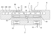
- FIG. 1 is a cross-sectional view of an embodiment of a pumping device
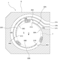
- FIG. 2 is a horizontal sectional view of the pump shown in FIG. 1
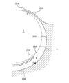
- FIG. Figure 3 shows the casing shown in Figure 2; It is a figure explaining the 1st volute side.
- FIG. 10 is a cross-sectional view showing another embodiment of a pump device
- FIG. 1 is a cross-sectional view showing one embodiment of a pump device.
- the pump device comprises a pump 1 for transferring liquid and a motor stator 2 for driving the pump 1 .
- the pump 1 comprises a casing 6 having a volute chamber 5 therein, and an impeller 7 arranged within the volute chamber 5 .
- the impeller 7 is provided with a plurality of permanent magnets 10. These permanent magnets 10 are embedded in the impeller 7 and are not exposed on the surface of the impeller 7 .
- the motor stator 2 comprises a plurality of coils 12 and power lines 15 for supplying current to these coils 12 . When current (more specifically, three-phase AC current) is supplied to the coil 12, the motor stator 2 generates a rotating magnetic field. This rotating magnetic field acts on the permanent magnet 10 of the impeller 7 to rotate the impeller 7 . A gap is formed between the pump 1 and the motor stator 2 so that the pump 1 can be separated from the motor stator 2 . Pump 1 may be fixed to motor stator 2 via a bracket (not shown).
- the casing 6 has a liquid suction port 18 .
- the impeller 7 rotates, the liquid flows into the pump 1 through the suction port 18 , is pressurized by the rotation of the impeller 7 , and is discharged from the pump 1 .
- liquids to be transferred by the pump 1 of the present embodiment include pure water, blood, and chemical solutions, but are not limited to these.
- the impeller 7 is completely non-contact supported, so particles and frictional heat due to sliding are not generated. Therefore, the pump 1 is suitable for transporting pure water of extremely high purity and blood that requires a constant temperature.
- FIG. 2 is a horizontal sectional view of the pump 1 shown in FIG.
- the impeller 7 is arranged inside the volute chamber 5 .
- Such a pump 1 is also called a volute pump.
- the impeller 7 has a plurality of blades 8 .
- the entire impeller 7 is circular.
- the casing 6 has three tongues 21A, 21B, 21C arranged at regular intervals around the impeller 7 and three side walls 22A, 22B, 22C connected to the tongues 21A, 21B, 21C, respectively. are doing.
- the three side walls 22A, 22B, 22C form three channels 23A, 23B, 23C for the liquid to be transported.
- the configuration of the pump 1 is Not limited to this embodiment, four or more tongues, sidewalls and channels may be provided.
- the liquid flows from the suction port 18 (see FIG. 1), flows through the impeller 7, and is pressurized as the impeller 7 rotates.
- the pressurized liquid flows through the three channels 23A, 23B, 23C.
- the channels 23A, 23B, 23C communicate with the volute chamber 5, and inlets 26A, 26B, 26C of the channels 23A, 23B, 23C face the volute chamber 5.
- the liquid separately flows through the three flow paths 23A, 23B, 23C and is discharged outside through the three outlets 27A, 27B, 27C of the three flow paths 23A, 23B, 23C.
- the liquid outlets 27A, 27B, 27C are separately provided corresponding to the three flow paths 23A, 23B, 23C.
- FIG. 3 is a diagram showing the casing 6 shown in FIG.
- the three sidewalls 22A, 22B, 22C have volute sides 30A, 30B, 30C, respectively, each of the volute sides 30A, 30B, 30C extending from one of the three tongues 21A, 21B, 21C. , extending beyond the other adjacent tongue. That is, the first sidewall 22A has a first volute side surface 30A extending from the first tongue 21A to which the first sidewall 22A is connected to a position beyond the adjacent second tongue 21B.
- the second side wall 22B has a second volute side 30B extending from the second tongue 21B to which the second side wall 22B is connected to a position beyond the adjacent third tongue 21C.
- the third side wall 22C has a third volute side 30C extending from the third tongue 21C to which the third side wall 22C is connected to a position beyond the adjacent first tongue 21A.
- FIG. 4 is an enlarged view showing the first volute side surface 30A.
- the start point S of the first volute side surface 30A is located at the connection point between the first tongue portion 21A and the side wall 22A, and the end point E of the first volute side surface 30A is located at the circumference of the impeller 7. directionally beyond the adjacent second tongue 21B.
- a first inlet 26A is formed between the first volute side 30A and the second tongue 21B.
- the second volute side surface 30B and the third volute side surface 30C have the same configuration as the first volute side surface 30A.
- volute side surfaces 30A, 30B, 30C are formed from the inner surfaces of the upstream side portions of the side walls 22A, 22B, 22C and face the volute chamber 5.
- the volute sides 30A, 30B, 30C form at least part of the volute chamber 5.
- the impeller 7 is surrounded by these volute side surfaces 30A, 30B, 30C.
- the three tongues 21A, 21B, 21C have the same shape.
- the volute sides 30A, 30B, 30C of the three sidewalls 22A, 22B, 22C have the same length. Furthermore, the volute sides 30A, 30B, 30C have the same shape.
- the term "same" not only means exactly the same, but also serves the intended purpose of creating a uniform pressure maximum around the impeller 7 to support the radial load of the impeller 7. It also means substantially the same, so far as achievable.
- the tongues 21A, 21B, and 21C are arranged rotationally symmetrically with respect to the center O of the volute chamber 5. That is, when the tongue 21A is rotated about the center O of the volute chamber 5 by an angle, the tongue 21A overlaps the tongue 21B, and the tongue 21A is rotated about the center O of the volute chamber 5 by an angle. Then, the tongue portion 21A overlaps the tongue portion 21C.
- the volute side surfaces 30A, 30B, and 30C are also arranged rotationally symmetrically with respect to the center O of the volute chamber 5.
- Inlets 26A, 26B, 26C of the flow paths 23A, 23B, 23C are arranged at regular intervals around the center O of the volute chamber 5 and have the same shape. Further, these three inlets 26A, 26B, 26C are arranged rotationally symmetrically with respect to the center O of the volute chamber 5. As shown in FIG.
- a mechanical radial bearing for supporting the impeller 7 is provided. This eliminates the need for the pump 1 and realizes the miniaturization of the pump 1, which could not be achieved in the past.
- the pump 1 does not have a mechanical radial bearing for supporting the impeller 7, so the pump 1 can be made very thin.
- the lengths of the three flow paths 23A, 23B, and 23C are different.
- the width of the channels may increase along with the length of the channels. That is, the longest first flow path 23A has the greatest width, the second longest second flow path 23B has a smaller width than the first flow path 23A, and the shortest third flow path 23B has a smaller width than the first flow path 23A.
- Channel 23C has a smaller width than second channel 23B.
- Such a flow channel shape is expected to contribute to the uniformity of the maximum pressure points R generated upstream of the three tongues 21A, 21B, and 21C.
- the pump 1 further comprises a pivot bearing 45 arranged between the back surface of the impeller 7 and the inner surface of the casing 6, as shown in FIG.
- the pivot bearing 45 is composed of a spherical body that is a separate structure from the impeller 7 and the casing 6 .
- a first recessed portion 41 is provided on the rear surface of the impeller 7
- a second recessed portion 42 facing the first recessed portion 41 is provided on the inner surface of the casing 6 .
- a spherical pivot bearing 45 is arranged between the first recess 41 and the second recess 42 , and positioning of the pivot bearing 45 is achieved by the first recess 41 and the second recess 42 .
- the pivot bearing 45 functions when the impeller 7 is started. More specifically, when the motor stator 2 generates a rotating magnetic field, the impeller 7 is drawn toward the motor stator 2 .
- the pivot bearing 45 supports the load of the impeller 7 toward the motor stator 2 and prevents the entire back surface of the impeller 7 from coming into contact with the inner surface of the casing 6 (surface contact). Since the impeller 7 can rotate around the pivot bearing 45, the impeller 7 can smoothly start its rotation.
- the pivot bearing 45 may be a protrusion protruding from the back surface of the impeller 7.
- pivot bearing 45 may be a curved or conical protrusion protruding from the back surface of impeller 7 .
- the pump 1 includes a non-contact thrust bearing 50 arranged on the suction side of the impeller 7 to receive the thrust load described above.
- the non-contact thrust bearing 50 is a hydrodynamic bearing. More specifically, a spiral groove 51 is formed on the surface of the impeller 7 on the suction side, and the spiral groove 51 generates dynamic pressure of the liquid when the impeller 7 rotates. The thrust load of the impeller 7 is received by the dynamic pressure of this liquid.
- the non-contact thrust bearing 50 may be a magnetic bearing.
- magnetic bearings using permanent magnets may be provided.
- a hydrodynamic bearing as shown in FIG. 1 is more suitable.
- FIG. 5 is a cross-sectional view showing another embodiment of the pump device.
- the configuration and operation of this embodiment, which are not specifically described, are the same as those of the embodiment described with reference to FIGS. 1 to 4, so redundant description thereof is omitted.
- the impeller 7 of the pump 1 of this embodiment has a return channel 60 formed at its center. This return channel 60 penetrates the impeller 7 in its axial direction.
- the pump 1 according to the embodiment shown in FIG. 5 is suitable for transporting blood.
- the present invention can be used for volute pumps that do not have a rotating shaft connected to an impeller.
Landscapes
- Engineering & Computer Science (AREA)
- Mechanical Engineering (AREA)
- General Engineering & Computer Science (AREA)
- Structures Of Non-Positive Displacement Pumps (AREA)
Abstract
本発明は、羽根車に連結された回転軸を持たないボリュートポンプに関する。ポンプ(1)のケーシング(6)は、羽根車(7)の周囲に等間隔で配列された少なくとも3つの舌部(21A,21B,21C)と、舌部(21A,21B,21C)にそれぞれ接続された少なくとも3つの側壁(22A,22B,22C)を有している。側壁(22A,22B,22C)は、液体のための少なくとも3つの流路(23A,23B,23C)を形成する。側壁(22A,22B,22Cのそれぞれは、舌部(21A,21B,21C)のうちの1つから、隣接する他の舌部を越えた位置まで延びるボリュート側面(30A,30B,30C)を有する。ポンプ(1)は、羽根車(7)を支持するためのラジアル軸受を備えていない。
Description
本発明は、液体を移送するためのポンプに関し、特に羽根車に連結された回転軸を持たないボリュートポンプに関する。
精密機器および医療機器等の分野において、液体の移送に使用されるポンプの小型化への要請がある。しかしながら、ポンプは、駆動源と羽根車とを連結する回転軸を有し、さらに回転軸を支持するための軸受を有するため、ポンプの小型化は難しい。そこで、回転軸を持たず、羽根車を支持するための非接触型ラジアル軸受を備えたポンプが開発されている。
非接触型ラジアル軸受の例として、磁気軸受および動圧軸受が挙げられる。磁気軸受は、コイルに電流を流すことにより発生した磁力により羽根車を非接触で支持するように構成され、動圧軸受は、液体の動圧により羽根車を非接触で支持するように構成される。これらの非接触型ラジアル軸受は、物理的な摺動を伴わないので、ポンプの高寿命化、発熱抑制、さらには液体へのパーティクルの混入を防ぐことができる。
しかしながら、上述した非接触型ラジアル軸受の少なくとも一部はポンプケーシング内に配置されるため、ポンプ全体の小型化には限界があった。特に、非接触型ラジアル軸受の存在のために、ポンプの厚み(軸方向の寸法)を小さくすることが難しかった。
そこで、本発明は、羽根車のラジアル荷重を受けるための機械的なラジアル軸受を不要とするポンプを提供する。
一態様では、液体を移送するためのポンプであって、内部にボリュート室を有するケーシングと、前記ボリュート室内に配置された羽根車を備え、前記ケーシングは、前記羽根車の周囲に等間隔で配列された少なくとも3つの舌部と、前記少なくとも3つの舌部にそれぞれ接続された少なくとも3つの側壁を有しており、前記少なくとも3つの側壁は、前記液体のための少なくとも3つの流路を形成し、前記少なくとも3つの側壁のそれぞれは、前記少なくとも3つの舌部のうちの1つから、隣接する他の舌部を越えた位置まで延びるボリュート側面を有し、前記ポンプは、前記羽根車を支持するためのラジアル軸受を備えていない、ポンプが提供される。
一態様では、液体を移送するためのポンプであって、内部にボリュート室を有するケーシングと、前記ボリュート室内に配置された羽根車を備え、前記ケーシングは、前記羽根車の周囲に等間隔で配列された少なくとも3つの舌部と、前記少なくとも3つの舌部にそれぞれ接続された少なくとも3つの側壁を有しており、前記少なくとも3つの側壁は、前記液体のための少なくとも3つの流路を形成し、前記少なくとも3つの側壁のそれぞれは、前記少なくとも3つの舌部のうちの1つから、隣接する他の舌部を越えた位置まで延びるボリュート側面を有し、前記少なくとも3つの舌部の上流側に発生する少なくとも3つの圧力極大点により、前記羽根車のラジアル荷重が支持されるように構成されている、ポンプが提供される。
一態様では、液体を移送するためのポンプであって、内部にボリュート室を有するケーシングと、前記ボリュート室内に配置された羽根車を備え、前記ケーシングは、前記羽根車の周囲に等間隔で配列された少なくとも3つの舌部と、前記少なくとも3つの舌部にそれぞれ接続された少なくとも3つの側壁を有しており、前記少なくとも3つの側壁は、前記液体のための少なくとも3つの流路を形成し、前記少なくとも3つの側壁のそれぞれは、前記少なくとも3つの舌部のうちの1つから、隣接する他の舌部を越えた位置まで延びるボリュート側面を有し、前記少なくとも3つの舌部の上流側に発生する少なくとも3つの圧力極大点により、前記羽根車のラジアル荷重のすべてが実質的に支持されるように構成されている、ポンプが提供される。
一態様では、前記少なくとも3つの舌部は、同じ形状を有する。
一態様では、前記少なくとも3つの舌部は、前記ボリュート室の中心に関して回転対称に配置されている。
一態様では、前記少なくとも3つの側壁の前記ボリュート側面は、同じ形状を有する。
一態様では、前記少なくとも3つの側壁の前記ボリュート側面は、前記ボリュート室の中心に関して回転対称に配置されている。
一態様では、前記少なくとも3つの流路の入口は、前記ボリュート室の中心に関して回転対称に配置されている。
一態様では、前記少なくとも3つの流路は、異なる長さおよび異なる幅を有し、各流路の長さが長いほど、各流路の幅は大きい。
一態様では、前記ポンプは、前記羽根車の背面と前記ケーシングの内面との間に配置されたピボット軸受をさらに備えている。
一態様では、前記ポンプは、前記羽根車の吸い込み側に配置された非接触型スラスト軸受をさらに備えている。
一態様では、前記少なくとも3つの舌部は、前記ボリュート室の中心に関して回転対称に配置されている。
一態様では、前記少なくとも3つの側壁の前記ボリュート側面は、同じ形状を有する。
一態様では、前記少なくとも3つの側壁の前記ボリュート側面は、前記ボリュート室の中心に関して回転対称に配置されている。
一態様では、前記少なくとも3つの流路の入口は、前記ボリュート室の中心に関して回転対称に配置されている。
一態様では、前記少なくとも3つの流路は、異なる長さおよび異なる幅を有し、各流路の長さが長いほど、各流路の幅は大きい。
一態様では、前記ポンプは、前記羽根車の背面と前記ケーシングの内面との間に配置されたピボット軸受をさらに備えている。
一態様では、前記ポンプは、前記羽根車の吸い込み側に配置された非接触型スラスト軸受をさらに備えている。
一態様では、上記ポンプと、回転磁界を発生させるように構成されたモータステータを備えている、ポンプ装置が提供される。
本発明によれば、羽根車の周囲に配列された少なくとも3つの舌部の上流側では、液体の圧力が局所的に高くなる。すなわち、羽根車の周囲に少なくとも3つの圧力極大点が等間隔に発生する。これらの圧力極大点は、羽根車のラジアル方向の荷重を支持することができる。したがって、羽根車のラジラル荷重を受けるためのラジアル軸受自体が不要となり、従来では達成できなかったポンプの小型化が実現される。
以下、本発明の実施形態について図面を参照して説明する。図1は、ポンプ装置の一実施形態を示す断面図である。ポンプ装置は、液体を移送するためのポンプ1と、ポンプ1を駆動するためのモータステータ2を備えている。ポンプ1は、内部にボリュート室5を有するケーシング6と、ボリュート室5内に配置された羽根車7を備えている。
羽根車7は、複数の永久磁石10を備えている。これら永久磁石10は羽根車7内に埋設されており、羽根車7の表面には露出していない。モータステータ2は、複数のコイル12と、これらコイル12に電流を供給する電力線15を備えている。コイル12に電流(より具体的には三相交流電流)が供給されると、モータステータ2は回転磁界を発生する。この回転磁界は、羽根車7の永久磁石10に作用し、羽根車7を回転させる。ポンプ1と、モータステータ2との間には隙間が形成されており、ポンプ1はモータステータ2から切り離すことが可能に構成されている。ポンプ1はブラケット(図示せず)を介してモータステータ2に固定されてもよい。
ケーシング6は、液体の吸込口18を有している。羽根車7の回転に伴い、液体は吸込口18からポンプ1内に流入し、羽根車7の回転により昇圧され、ポンプ1から吐き出される。本実施形態のポンプ1によって移送される対象の液体の例としては、純水、血液、薬液などが挙げられるが、これらに限定されるものではない。特に、以下に説明するように、羽根車7は、完全に非接触で支持されるので、摺動に起因するパーティクルおよび摩擦熱が発生しない。したがって、ポンプ1は、極めて純度の高い純水や、一定温度が求められる血液の移送に適している。
図2は、図1に示すポンプ1の水平断面図である。図2に示すように、羽根車7はボリュート室5内に配置されている。このようなポンプ1は、ボリュートポンプとも呼ばれる。羽根車7は、複数の翼8を有している。羽根車7の全体は円形である。ケーシング6は、羽根車7の周囲に等間隔で配列された3つの舌部21A,21B,21Cと、これら舌部21A,21B,21Cにそれぞれ接続された3つの側壁22A,22B,22Cを有している。3つの側壁22A,22B,22Cは、移送される液体のための3つの流路23A,23B,23Cを形成している。本実施形態では、3つの舌部21A,21B,21C、対応する3つの側壁22A,22B,22C、および対応する3つの流路23A,23B,23Cが設けられているが、ポンプ1の構成はこの実施形態には限定されず、4つまたはそれよりも多い舌部、側壁、流路が設けられてもよい。
羽根車7が回転すると、液体は吸込口18(図1参照)から流入し、羽根車7内を流れ、羽根車7の回転に伴って昇圧される。昇圧された液体は、3つの流路23A,23B,23Cを流れる。流路23A,23B,23Cは、ボリュート室5に連通しており、流路23A,23B,23Cの入口26A,26B,26Cは、ボリュート室5に面している。液体は、3つの流路23A,23B,23Cを別々に流れ、3つの流路23A,23B,23Cの3つの出口27A,27B,27Cを通って外部に排出される。液体の出口27A,27B,27Cは、3つの流路23A,23B,23Cに対応して別々に設けられている。
図3は、図2に示すケーシング6を示す図である。3つの側壁22A,22B,22Cは、ボリュート側面30A,30B,30Cをそれぞれ有しており、ボリュート側面30A,30B,30Cのそれぞれは、3つの舌部21A,21B,21Cのうちの1つから、隣接する他の舌部を越えた位置まで延びている。すなわち、第1側壁22Aは、第1側壁22Aが接続される第1舌部21Aから、隣接する第2舌部21Bを越えた位置まで延びる第1ボリュート側面30Aを有する。第2側壁22Bは、第2側壁22Bが接続される第2舌部21Bから、隣接する第3舌部21Cを越えた位置まで延びる第2ボリュート側面30Bを有する。第3側壁22Cは、第3側壁22Cが接続される第3舌部21Cから、隣接する第1舌部21Aを越えた位置まで延びる第3ボリュート側面30Cを有する。
図4は、第1ボリュート側面30Aを示す拡大図である。図4に示すように、第1ボリュート側面30Aの始点Sは、第1舌部21Aと側壁22Aとの接続点に位置しており、第1ボリュート側面30Aの終点Eは、羽根車7の周方向において、隣接する第2舌部21Bを越えた位置にある。第1入口26Aは、第1ボリュート側面30Aと第2舌部21Bとの間に形成される。図示しないが、第2ボリュート側面30Bおよび第3ボリュート側面30Cも第1ボリュート側面30Aと同じ構成である。
図3に示すように、ボリュート側面30A,30B,30Cは、側壁22A,22B,22Cの上流側部位の内面から構成されており、ボリュート室5に面している。ボリュート側面30A,30B,30Cは、ボリュート室5の少なくとも一部を形成する。羽根車7は、これらボリュート側面30A,30B,30Cに囲まれている。
3つの舌部21A,21B,21Cは、同じ形状を有している。3つの側壁22A,22B,22Cのボリュート側面30A,30B,30Cは、同じ長さを有している。さらに、ボリュート側面30A,30B,30Cは、同じ形状を有している。本明細書において、「同じ」とは、完全に同じという意味のみならず、羽根車7の周囲に均一の圧力極大点を形成して、羽根車7のラジアル荷重を支持するという意図した目的を達成できる限りにおいて、実質的に同じであることも意味する。
舌部21A,21B,21Cは、ボリュート室5の中心Oに関して回転対称に配置されている。すなわち、舌部21Aをボリュート室5の中心Oの周りにある角度だけ回転させると、舌部21Aは舌部21Bに重なり、さらに舌部21Aをボリュート室5の中心Oの周りにある角度だけ回転させると、舌部21Aは舌部21Cに重なる。
ボリュート側面30A,30B,30Cも、ボリュート室5の中心Oに関して回転対称に配置されている。流路23A,23B,23Cのそれぞれの入口26A,26B,26Cは、ボリュート室5の中心Oの周りに等間隔で配列されており、同じ形状を有している。さらに、これら3つの入口26A,26B,26Cは、ボリュート室5の中心Oに関して回転対称に配置されている。
本発明者が実施した流体解析によれば、上記回転対称構造を有するポンプ1の3つの舌部21A,21B,21Cの上流側では、液体の圧力が局所的に高くなる領域である圧力極大点Rが存在することが分かった。特に、羽根車7の周囲に3つの均一な圧力極大点Rが等間隔に発生することが流体解析の結果から明らかになった。これらの圧力極大点Rは、羽根車7の周囲に等間隔で存在するので、羽根車7のラジアル荷重のすべてを実質的に支持することができる。3つの舌部21A,21B,21Cの上流側に発生する3つの均一な圧力極大点Rにより羽根車7のラジアル荷重が支持されるので、羽根車7を支持するための機械的なラジアル軸受が不要となり、従来では達成できなかったポンプ1の小型化が実現される。特に、本実施形態によれば、ポンプ1は、羽根車7を支持するための機械的なラジアル軸受を備えていないので、ポンプ1を非常に薄くすることができる。
図2に示すように、3つの流路23A,23B,23Cの長さは異なっている。液体に対する流路の抵抗を3つの流路23A,23B,23C間で均一にするために、一実施形態では、流路の長さに従って流路の幅を大きくしてもよい。すなわち、最も長い第1の流路23Aは最も大きな幅を有し、2番目に長い第2の流路23Bは、第1の流路23Aよりも小さな幅を有し、最も短い第3の流路23Cは第2の流路23Bよりも小さな幅を有する。このような流路形状は、3つの舌部21A,21B,21Cの上流側に発生する圧力極大点Rの均一化に寄与すると期待される。
図1に示すように、ポンプ1は、羽根車7の背面とケーシング6の内面との間に配置されたピボット軸受45をさらに備えている。このピボット軸受45は、羽根車7およびケーシング6とは別の構造体である球体から構成されている。羽根車7の背面には第1凹部41が設けられており、ケーシング6の内面には、第1凹部41に対向する第2凹部42が設けられている。球体からなるピボット軸受45は、第1凹部41と第2凹部42との間に配置されており、第1凹部41および第2凹部42によってピボット軸受45の位置決めが達成される。
ピボット軸受45は、羽根車7の始動時に機能する。より具体的には、モータステータ2により回転磁界が発生すると、羽根車7はモータステータ2に向かって引き寄せられる。ピボット軸受45は、モータステータ2に向かう羽根車7の荷重を支持し、羽根車7の背面の全体がケーシング6の内面に接触する(面接触)することを防止する。羽根車7は、ピボット軸受45を中心に回転することが可能であるので、羽根車7はスムーズにその回転を開始することができる。
ピボット軸受45の存在により、羽根車7の背面とケーシング6の内面との間には隙間が常に形成されている。液体は、吸込口18から流入され、羽根車7の回転に伴って昇圧される。昇圧された液体は、羽根車7の背面とケーシング6の内面との隙間を満たし、羽根車7を吸い込み側に押すスラスト荷重を発生させる。このスラスト荷重により羽根車7は吸い込み側に移動され、結果として、羽根車7はピボット軸受45から離れる。すなわち、ポンプ1の運転時には羽根車7はピボット軸受45とは非接触となる。
一実施形態では、ピボット軸受45は、羽根車7の背面から突出した突起であってもよい。例えば、ピボット軸受45は、羽根車7の背面から突出した曲面突起または円錐突起であってもよい。
図1に示すように、ポンプ1は、上述したスラスト荷重を受けるために、羽根車7の吸い込み側に配置された非接触型スラスト軸受50を備えている。図1に示す実施形態では、非接触型スラスト軸受50は動圧軸受である。より具体的には、羽根車7の吸い込み側の面にはスパイラル溝51が形成されており、スパイラル溝51は羽根車7の回転時に液体の動圧を発生させる。この液体の動圧により羽根車7のスラスト荷重が受けられる。
一実施形態では、非接触型スラスト軸受50は、磁気軸受であってもよい。例えば、永久磁石を利用した磁気軸受が設けられてもよい。ただし、ポンプ1の小型化を達成する観点からは、図1に示すような動圧軸受がより適している。
図5は、ポンプ装置の他の実施形態を示す断面図である。特に説明しない本実施形態の構成および動作は、図1乃至図4を参照して説明した実施形態と同じであるので、その重複する説明を省略する。本実施形態のポンプ1の羽根車7は、その中心に形成された戻り流路60を有している。この戻り流路60は、羽根車7をその軸方向に貫通している。
羽根車7の回転に伴い、液体は、吸込口18から流入され、羽根車7の回転に伴って昇圧される。昇圧された液体の一部は、羽根車7の背面とケーシング6の内面との隙間を満たし、戻り流路60を通って羽根車7の吸い込み側に流れる。このような液体の流れは、羽根車7の背面とケーシング6の内面との隙間での液体の淀み(停滞)を防止することができる。図5に示す実施形態に係るポンプ1は、血液の移送に好適である。
上述した実施形態は、本発明が属する技術分野における通常の知識を有する者が本発明を実施できることを目的として記載されたものである。上記実施形態の種々の変形例は、当業者であれば当然になしうることであり、本発明の技術的思想は他の実施形態にも適用しうる。したがって、本発明は、記載された実施形態に限定されることはなく、特許請求の範囲によって定義される技術的思想に従った最も広い範囲に解釈されるものである。
本発明は、羽根車に連結された回転軸を持たないボリュートポンプに利用可能である。
1 ポンプ
2 モータステータ
5 ボリュート室
6 ケーシング
7 羽根車
8 翼
10 永久磁石
12 コイル
15 電力線
18 吸込口
21A,21B,21C 舌部
22A,22B,22C 側壁
23A,23B,23C 流路
26A,26B,26C 入口
27A,27B,27C 出口
30A,30B,30C ボリュート側面
41 第1凹部
42 第2凹部
45 ピボット軸受
50 非接触型スラスト軸受
51 スパイラル溝
60 戻り流路
2 モータステータ
5 ボリュート室
6 ケーシング
7 羽根車
8 翼
10 永久磁石
12 コイル
15 電力線
18 吸込口
21A,21B,21C 舌部
22A,22B,22C 側壁
23A,23B,23C 流路
26A,26B,26C 入口
27A,27B,27C 出口
30A,30B,30C ボリュート側面
41 第1凹部
42 第2凹部
45 ピボット軸受
50 非接触型スラスト軸受
51 スパイラル溝
60 戻り流路
Claims (12)
- 液体を移送するためのポンプであって、
内部にボリュート室を有するケーシングと、
前記ボリュート室内に配置された羽根車を備え、
前記ケーシングは、
前記羽根車の周囲に等間隔で配列された少なくとも3つの舌部と、
前記少なくとも3つの舌部にそれぞれ接続された少なくとも3つの側壁を有しており、
前記少なくとも3つの側壁は、前記液体のための少なくとも3つの流路を形成し、
前記少なくとも3つの側壁のそれぞれは、前記少なくとも3つの舌部のうちの1つから、隣接する他の舌部を越えた位置まで延びるボリュート側面を有し、
前記ポンプは、前記羽根車を支持するためのラジアル軸受を備えていない、ポンプ。 - 液体を移送するためのポンプであって、
内部にボリュート室を有するケーシングと、
前記ボリュート室内に配置された羽根車を備え、
前記ケーシングは、
前記羽根車の周囲に等間隔で配列された少なくとも3つの舌部と、
前記少なくとも3つの舌部にそれぞれ接続された少なくとも3つの側壁を有しており、
前記少なくとも3つの側壁は、前記液体のための少なくとも3つの流路を形成し、
前記少なくとも3つの側壁のそれぞれは、前記少なくとも3つの舌部のうちの1つから、隣接する他の舌部を越えた位置まで延びるボリュート側面を有し、
前記少なくとも3つの舌部の上流側に発生する少なくとも3つの圧力極大点により、前記羽根車のラジアル荷重が支持されるように構成されている、ポンプ。 - 液体を移送するためのポンプであって、
内部にボリュート室を有するケーシングと、
前記ボリュート室内に配置された羽根車を備え、
前記ケーシングは、
前記羽根車の周囲に等間隔で配列された少なくとも3つの舌部と、
前記少なくとも3つの舌部にそれぞれ接続された少なくとも3つの側壁を有しており、
前記少なくとも3つの側壁は、前記液体のための少なくとも3つの流路を形成し、
前記少なくとも3つの側壁のそれぞれは、前記少なくとも3つの舌部のうちの1つから、隣接する他の舌部を越えた位置まで延びるボリュート側面を有し、
前記少なくとも3つの舌部の上流側に発生する少なくとも3つの圧力極大点により、前記羽根車のラジアル荷重のすべてが実質的に支持されるように構成されている、ポンプ。 - 前記少なくとも3つの舌部は、同じ形状を有する、請求項1乃至3のいずれか一項に記載のポンプ。
- 前記少なくとも3つの舌部は、前記ボリュート室の中心に関して回転対称に配置されている、請求項4に記載のポンプ。
- 前記少なくとも3つの側壁の前記ボリュート側面は、同じ形状を有する、請求項1乃至5のいずれか一項に記載のポンプ。
- 前記少なくとも3つの側壁の前記ボリュート側面は、前記ボリュート室の中心に関して回転対称に配置されている、請求項6に記載のポンプ。
- 前記少なくとも3つの流路の入口は、前記ボリュート室の中心に関して回転対称に配置されている、請求項1乃至7のいずれか一項に記載のポンプ。
- 前記少なくとも3つの流路は、異なる長さおよび異なる幅を有し、
各流路の長さが長いほど、各流路の幅は大きい、請求項1乃至8のいずれか一項に記載のポンプ。 - 前記羽根車の背面と前記ケーシングの内面との間に配置されたピボット軸受をさらに備えている、請求項1乃至9のいずれか一項に記載のポンプ。
- 前記羽根車の吸い込み側に配置された非接触型スラスト軸受をさらに備えている、請求項1乃至10のいずれか一項に記載のポンプ。
- 請求項1乃至11のいずれか一項に記載のポンプと、
回転磁界を発生させるように構成されたモータステータを備えている、ポンプ装置。
Applications Claiming Priority (2)
| Application Number | Priority Date | Filing Date | Title |
|---|---|---|---|
| JP2021196687A JP2023082774A (ja) | 2021-12-03 | 2021-12-03 | ポンプ |
| JP2021-196687 | 2021-12-03 |
Publications (1)
| Publication Number | Publication Date |
|---|---|
| WO2023101030A1 true WO2023101030A1 (ja) | 2023-06-08 |
Family
ID=86612470
Family Applications (1)
| Application Number | Title | Priority Date | Filing Date |
|---|---|---|---|
| PCT/JP2022/044661 Ceased WO2023101030A1 (ja) | 2021-12-03 | 2022-12-05 | ポンプ |
Country Status (2)
| Country | Link |
|---|---|
| JP (1) | JP2023082774A (ja) |
| WO (1) | WO2023101030A1 (ja) |
Citations (4)
| Publication number | Priority date | Publication date | Assignee | Title |
|---|---|---|---|---|
| JP2003097491A (ja) * | 2001-09-26 | 2003-04-03 | Mitsubishi Heavy Ind Ltd | 立軸単段ポンプ |
| JP2004144070A (ja) * | 2002-08-30 | 2004-05-20 | Senko Medical Instr Mfg Co Ltd | 遠心ポンプ |
| JP2005270415A (ja) * | 2004-03-25 | 2005-10-06 | Terumo Corp | 遠心式血液ポンプ装置 |
| JP2007044302A (ja) * | 2005-08-10 | 2007-02-22 | Tokyo Medical & Dental Univ | 遠心ポンプの流量及び揚程測定方法、装置、及び、拍動する循環系の循環状態評価装置 |
Family Cites Families (1)
| Publication number | Priority date | Publication date | Assignee | Title |
|---|---|---|---|---|
| US20070077155A1 (en) * | 2005-09-30 | 2007-04-05 | Intel Corporation | Centrifugal pump with hydrodynamic bearing and double involute |
-
2021
- 2021-12-03 JP JP2021196687A patent/JP2023082774A/ja active Pending
-
2022
- 2022-12-05 WO PCT/JP2022/044661 patent/WO2023101030A1/ja not_active Ceased
Patent Citations (4)
| Publication number | Priority date | Publication date | Assignee | Title |
|---|---|---|---|---|
| JP2003097491A (ja) * | 2001-09-26 | 2003-04-03 | Mitsubishi Heavy Ind Ltd | 立軸単段ポンプ |
| JP2004144070A (ja) * | 2002-08-30 | 2004-05-20 | Senko Medical Instr Mfg Co Ltd | 遠心ポンプ |
| JP2005270415A (ja) * | 2004-03-25 | 2005-10-06 | Terumo Corp | 遠心式血液ポンプ装置 |
| JP2007044302A (ja) * | 2005-08-10 | 2007-02-22 | Tokyo Medical & Dental Univ | 遠心ポンプの流量及び揚程測定方法、装置、及び、拍動する循環系の循環状態評価装置 |
Also Published As
| Publication number | Publication date |
|---|---|
| JP2023082774A (ja) | 2023-06-15 |
Similar Documents
| Publication | Publication Date | Title |
|---|---|---|
| CN103026597B (zh) | 流体冷却的电机 | |
| JP6512792B2 (ja) | 磁気浮上型ポンプ | |
| US9850906B2 (en) | Rotation drive device and centrifugal pump apparatus employing same | |
| EP2741793B1 (en) | Rotary pump comprising a rotor and delivery elements | |
| US11085711B2 (en) | Cooling device | |
| KR20210141491A (ko) | 캔드 모터와 그에 의해 구동하는 펌프, 및 그것을 사용한 로켓 엔진 시스템과 액체 연료 로켓 | |
| CN111436205A (zh) | 具有整体冷却的电机及独立控制的转子速度的模块化多级整体密封电动泵 | |
| JP2007089972A (ja) | 遠心式血液ポンプ装置 | |
| JP2009254436A (ja) | 動圧軸受を備えた人工心臓ポンプ | |
| US20160053769A1 (en) | Dynamic pressure bearing pump | |
| US20220069665A1 (en) | Electric motor assembly | |
| US11015608B2 (en) | Axial flow pump with reduced height dimension | |
| TW200535343A (en) | Pump | |
| CN114001036A (zh) | 一种微型水力悬浮机械泵及其装配方法 | |
| WO2023101030A1 (ja) | ポンプ | |
| US20160053770A1 (en) | Dynamic pressure bearing pump | |
| CN110462218B (zh) | 具有轴向磁通电动机的离心泵组件及其组装方法 | |
| US20230006514A1 (en) | Rotation device | |
| US11846285B2 (en) | Pump with a bearing lubrication system | |
| KR101071922B1 (ko) | 모터 | |
| US20190048866A1 (en) | Pump arrangement | |
| US20060099068A1 (en) | Axial flow pump | |
| CN115539400A (zh) | 一种盘式磁阻电机集成叶轮离心式双吸泵 | |
| JP4834388B2 (ja) | 渦流ポンプ | |
| CN211082298U (zh) | 一种旋涡式微型泵 |
Legal Events
| Date | Code | Title | Description |
|---|---|---|---|
| 121 | Ep: the epo has been informed by wipo that ep was designated in this application |
Ref document number: 22901460 Country of ref document: EP Kind code of ref document: A1 |
|
| NENP | Non-entry into the national phase |
Ref country code: DE |
|
| 122 | Ep: pct application non-entry in european phase |
Ref document number: 22901460 Country of ref document: EP Kind code of ref document: A1 |