WO2023100730A1 - 電気コネクタ及びこれを備えた電気コネクタ対 - Google Patents
電気コネクタ及びこれを備えた電気コネクタ対 Download PDFInfo
- Publication number
- WO2023100730A1 WO2023100730A1 PCT/JP2022/043281 JP2022043281W WO2023100730A1 WO 2023100730 A1 WO2023100730 A1 WO 2023100730A1 JP 2022043281 W JP2022043281 W JP 2022043281W WO 2023100730 A1 WO2023100730 A1 WO 2023100730A1
- Authority
- WO
- WIPO (PCT)
- Prior art keywords
- retainer
- housing
- electrical connector
- terminal
- wall
- Prior art date
- Legal status (The legal status is an assumption and is not a legal conclusion. Google has not performed a legal analysis and makes no representation as to the accuracy of the status listed.)
- Ceased
Links
Images


Classifications
-
- H—ELECTRICITY
- H01—ELECTRIC ELEMENTS
- H01R—ELECTRICALLY-CONDUCTIVE CONNECTIONS; STRUCTURAL ASSOCIATIONS OF A PLURALITY OF MUTUALLY-INSULATED ELECTRICAL CONNECTING ELEMENTS; COUPLING DEVICES; CURRENT COLLECTORS
- H01R13/00—Details of coupling devices of the kinds covered by groups H01R12/70 or H01R24/00 - H01R33/00
- H01R13/40—Securing contact members in or to a base or case; Insulating of contact members
- H01R13/42—Securing in a demountable manner
- H01R13/436—Securing a plurality of contact members by one locking piece or operation
- H01R13/4361—Insertion of locking piece perpendicular to direction of contact insertion
-
- H—ELECTRICITY
- H01—ELECTRIC ELEMENTS
- H01R—ELECTRICALLY-CONDUCTIVE CONNECTIONS; STRUCTURAL ASSOCIATIONS OF A PLURALITY OF MUTUALLY-INSULATED ELECTRICAL CONNECTING ELEMENTS; COUPLING DEVICES; CURRENT COLLECTORS
- H01R12/00—Structural associations of a plurality of mutually-insulated electrical connecting elements, specially adapted for printed circuits, e.g. printed circuit boards [PCB], flat or ribbon cables, or like generally planar structures, e.g. terminal strips, terminal blocks; Coupling devices specially adapted for printed circuits, flat or ribbon cables, or like generally planar structures; Terminals specially adapted for contact with, or insertion into, printed circuits, flat or ribbon cables, or like generally planar structures
- H01R12/70—Coupling devices
- H01R12/71—Coupling devices for rigid printing circuits or like structures
- H01R12/72—Coupling devices for rigid printing circuits or like structures coupling with the edge of the rigid printed circuits or like structures
- H01R12/722—Coupling devices for rigid printing circuits or like structures coupling with the edge of the rigid printed circuits or like structures coupling devices mounted on the edge of the printed circuits
-
- H—ELECTRICITY
- H01—ELECTRIC ELEMENTS
- H01R—ELECTRICALLY-CONDUCTIVE CONNECTIONS; STRUCTURAL ASSOCIATIONS OF A PLURALITY OF MUTUALLY-INSULATED ELECTRICAL CONNECTING ELEMENTS; COUPLING DEVICES; CURRENT COLLECTORS
- H01R13/00—Details of coupling devices of the kinds covered by groups H01R12/70 or H01R24/00 - H01R33/00
- H01R13/40—Securing contact members in or to a base or case; Insulating of contact members
- H01R13/42—Securing in a demountable manner
- H01R13/422—Securing in resilient one-piece base or case, e.g. by friction; One-piece base or case formed with resilient locking means
- H01R13/4223—Securing in resilient one-piece base or case, e.g. by friction; One-piece base or case formed with resilient locking means comprising integral flexible contact retaining fingers
-
- H—ELECTRICITY
- H01—ELECTRIC ELEMENTS
- H01R—ELECTRICALLY-CONDUCTIVE CONNECTIONS; STRUCTURAL ASSOCIATIONS OF A PLURALITY OF MUTUALLY-INSULATED ELECTRICAL CONNECTING ELEMENTS; COUPLING DEVICES; CURRENT COLLECTORS
- H01R13/00—Details of coupling devices of the kinds covered by groups H01R12/70 or H01R24/00 - H01R33/00
- H01R13/46—Bases; Cases
- H01R13/502—Bases; Cases composed of different pieces
- H01R13/506—Bases; Cases composed of different pieces assembled by snap action of the parts
Definitions
- the present invention relates to an electrical connector provided with a retainer for holding a plurality of metal terminals housed in a housing and an electrical connector pair provided with the same.
- the locking projections formed on the retainer are arranged perpendicularly to the insertion direction of the retainer on the outer wall and inner wall of the housing (that is, on which the metal terminals are respectively accommodated). Therefore, the holding strength of the retainer with respect to the housing (that is, the ability to prevent the retainer from coming off from the housing) depends on the rigidity and strength of the members that make up the outer and inner walls of the housing ( wall thickness, shape, etc.).
- an object of the present invention is to provide an electrical connector that can stably secure the holding strength of the retainer to the housing, and an electrical connector pair including the same.
- a first aspect of the present invention is an electrical connector (5) comprising a plurality of metal terminals (31) and a plurality of terminal receiving chambers (31) into which the plurality of metal terminals are respectively inserted. 47), and a housing (33) having a retainer insertion hole (51) extending in a lateral direction orthogonal to the front-rear direction corresponding to the insertion direction of the plurality of metal terminals; a retainer (35) for holding the plurality of metal terminals inserted into the plurality of terminal accommodating chambers, wherein the plurality of terminal accommodating chambers are arranged so as to form a row along the left-right direction; , constitute a first terminal receiving chamber group (101) and a second terminal receiving chamber group (102), respectively.
- the housing has a partition wall (48) disposed between the first terminal receiving chamber group and the second terminal receiving chamber group, and is spaced apart in the vertical direction orthogonal to the left and right direction.
- a retainer opening (52) forming a part of the retainer insertion hole is formed in the partition wall, and the retainer is engaged with the housing while being inserted into the retainer insertion hole.
- An engaging portion (57) is provided, and an engaging portion (55) for engaging the engaging portion of the retainer is formed in the retainer opening.
- the locking portion for locking the locked portion of the retainer is formed in the retainer opening formed in the partition wall arranged between the first and second terminal receiving chamber groups. Therefore, it is possible to stably secure the holding strength of the retainer with respect to the housing.
- a second aspect is the first aspect, wherein the engaged portion of the retainer is a projection (57) projecting forward or rearward of the retainer, and the retainer is such that the projection is It has an insertion side portion (71) formed and a base portion (73) connected to the insertion side portion, and the size of the front-rear direction width of the insertion side portion including the projection is equal to or less than the front-rear direction width of the base portion.
- the retainer is positioned at the base relative to the housing while suppressing an increase in the width of the retainer in the front-rear direction (that is, the width in the insertion direction of the metal terminal). A width in the front-rear direction required for stable holding can be secured.
- the housing has an upper wall (41) and a lower wall (42) forming an outer shell thereof, and the housing is separated from the partition wall via the partition wall.
- a plurality of inner walls (49) are provided so as to connect the upper wall and the lower wall in the vertical direction, respectively, and are arranged at predetermined intervals in the horizontal direction, and the plurality of inner walls are connected to the terminals.
- Notch portions (59A, 59B) forming left and right side walls of the storage chamber and forming a part of the retainer insertion hole are provided, respectively, and correspond to the insertion side portions of the retainer among the plurality of inner walls.
- the notch (59A) in the inner wall may have a width in the front-rear direction smaller than the notch (59B) in the inner wall corresponding to the base of the retainer.
- the inner wall having the notch portions with different widths in the front-rear direction so as to correspond to the insertion side portion and the base portion the insertion side portion and the front-rear direction width of the retainer having a smaller front-rear direction width can be increased.
- Each base of a large retainer can be stably held.
- the insertion side portion has a long hole (87) arranged inside the projection and penetrating the insertion side portion in the vertical direction. may be provided.
- the portion between the protrusion and the long hole of the retainer can be easily deformed, so that the protrusion can be easily locked to the locking portion of the housing.
- the retainer may have a cover piece (88) arranged to cover at least one opening of the long hole in the through direction of the long hole. good.
- the metal terminal inserted into the terminal accommodating chamber in the first terminal accommodating chamber group and positioned near the elongated hole and the metal terminal inserted into the terminal accommodating chamber in the second terminal accommodating chamber group and having a long It is possible to prevent unintentional electrical connection (that is, short circuit) from occurring through the elongated hole with a metal terminal located near the hole.
- an elastic deformation elastically deforming elastic deformation is provided between the projection of the retainer and the elongated hole when the projection is locked to the locking portion.
- a portion (89) may be formed, and the vertical width of the elastic deformation portion may be smaller than the maximum vertical width of the entire insertion side portion.
- the vertical width of the elastically deformable portion is smaller than the maximum vertical width of the entire insertion side portion, the rigidity of the insertion side portion can be secured, and the gap between the projection of the retainer and the long hole can be reduced. It is possible to avoid obstruction of deformation of the elastically deformable portion.
- the metal terminal is a female metal terminal (31) connectable to a male metal terminal
- the housing comprises the It may be a female side housing (33) connectable to a male side housing holding a male metal terminal.
- the structure for engaging the retainer and the metal terminal can be easily secured by the female metal terminal, so the structure of the electrical connector provided with the retainer is simplified.
- an eighth aspect of the present invention provides the electrical connector according to any one aspect of the first to seventh aspects and another electrical connector (5) connectable to the electrical connector (5).
- An electrical connector pair (1) comprising an electrical connector (3).
- the retained portion of the retainer is engaged with the retainer opening formed in the partition wall disposed between the first and second terminal receiving chamber groups. Since the locking portion for locking is formed, it is possible to stably secure the holding strength of the retainer with respect to the housing.
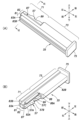
- FIG. 3 is an explanatory view showing the attachment operation of the retainer 35 to the female housing 33 (the female housing 33 corresponds to the section taken along line VII-VII in FIG. 3).
- FIG. 3 is an explanatory view showing the attachment operation of the retainer to the female side housing 33 (here, the female side housing 33 corresponds to the VIII-VIII line section in FIG. 3).
- FIG. 3 is an explanatory view showing a state in which the female terminal 31 is held by the retainer 35 (cross-sectional view taken along line IX-IX in FIG. 3); Explanatory drawing showing the holding state of the female terminal 31 by the retainer 35 (cross-sectional view taken along the line X-X in FIG. 3)
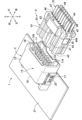
- the electrical connector pair 1 is a device for electrically connecting wires to each other or between a wire and a circuit board of an electrical appliance.
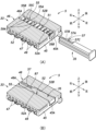
- the electrical connector pair 1 includes a male connector 3 and a female connector 5 (an example of electrical connectors) connectable to each other.
- the male connector 3 has a plurality of male metal terminals (hereinafter referred to as male terminals) 11 and a resin male housing 13 that accommodates the male terminals 11 .
- the plurality of male terminals 11 each have a pin-shaped tip portion 11A, and are arranged at predetermined intervals in the male housing 13 so as to form a row along the left-right direction.
- the plurality of male terminals 11 are arranged in two rows in the vertical direction.
- the male housing 13 has a box-like shape with a substantially rectangular opening 13A on the rear side.
- the male housing 13 has a top wall 15, a bottom wall 16, a left wall 17, a right wall 18, and a front wall 19 that form its outer shell.
- Aperture 13A is defined by the rear edges of top wall 15, bottom wall 16, left wall 17, and right wall 18.
- the male side housing 13 is fixed to the circuit board 21 by means of mounting brackets 23 with the lower wall 16 of the male side housing 13 contacting the circuit board 21 .
- the circuit board 21 is electrically connected to the male terminals 11 .
- the plurality of male terminals 11 may be connected to electric wires instead of the circuit board 21 .
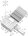
- the female connector 5 includes a plurality of female metal terminals (hereinafter referred to as female terminals) 31, a resin female housing 33 for accommodating the female terminals 31, and a female terminal. and a resin retainer 35 attached to the housing 33 .
- female terminals female metal terminals
- resin female housing 33 for accommodating the female terminals 31, and a female terminal.
- resin retainer 35 attached to the housing 33 .
- Each female terminal 31 has a square cylindrical portion 31A located on the front side and a crimping portion 31B located on the rear side. An electric wire 34 is connected to each crimping portion 31B. Each female terminal 31 can be electrically connected to the male terminal 11 arranged at the corresponding position in the male connector 3 .
- the female housing 33 has a substantially rectangular parallelepiped shape, and has an upper wall 41, a lower wall 42, a front wall 43 (see FIG. 3), a rear wall 44, a left wall 45, and a right wall 46, which form its outer shell.
- the female housing 33 has a partition wall 48 and an inner wall 49 arranged so as to partition its inner space.
- the partition wall 48 is arranged substantially parallel to and between the upper wall 41 and the lower wall 42 .
- the female housing 33 has a complementary structure connectable with the male housing 13 .
- the female housing 33 can be fitted with the male housing 13 by inserting the female housing 33 into the male housing 13 through the opening 13A of the male housing 13 except for a part thereof (that is, the rear portion).
- a plurality of terminal accommodating chambers 47 into which the plurality of female terminals 31 are respectively inserted are formed in the female housing 33 .
- Each terminal receiving chamber 47 has a substantially rectangular parallelepiped space that extends in the front-rear direction so as to pass through the front wall 43 and the rear wall 44 .
- the plurality of terminal receiving chambers 47 are arranged in rows along the left-right direction to form a first terminal receiving chamber group 101 and a second terminal receiving chamber group 102, respectively.
- the first terminal receiving chamber group 101 and the second terminal receiving chamber group 102 are arranged with an interval therebetween in the vertical direction.
- the first terminal receiving chamber group 101 and the second terminal receiving chamber group 102 each include the same number of terminal receiving chambers 47, and the terminal receiving chambers 47 are arranged so as to overlap in the vertical direction.
- each terminal accommodating chamber 47 In the first terminal accommodating chamber group 101, the upper and lower surfaces of each terminal accommodating chamber 47 are generally defined by the upper wall 41 and the partition wall 48, respectively. Left and right side surfaces of each terminal receiving chamber 47 are generally defined by one of a plurality of inner walls 49 , left walls 45 and right walls 46 .
- the inner wall 49 is provided so as to vertically connect the upper wall 41 and the lower wall 42 via the partition wall 48 when viewed in the front-rear direction.
- the upper wall 41 and the partition wall 48 function as upper walls and lower walls of the plurality of terminal accommodating chambers 47 in the first terminal accommodating chamber group 101, respectively.
- the inner wall 49 , the left wall 45 and the right wall 46 also function as side walls of the plurality of terminal accommodating chambers 47 in the first terminal accommodating chamber group 101 .
- each terminal accommodating chamber 47 is generally defined by the partition wall 48 and the lower wall 42, respectively.
- Left and right side surfaces of each terminal receiving chamber 47 are generally defined by one of a plurality of inner walls 49 , left walls 45 and right walls 46 .
- the partition wall 48 and the lower wall 42 function as upper and lower walls of the plurality of terminal accommodating chambers 47 in the second terminal accommodating chamber group 102, respectively.
- the inner wall 49 , the left wall 45 and the right wall 46 also function as side walls of the plurality of terminal accommodating chambers 47 in the second terminal accommodating chamber group 102 .
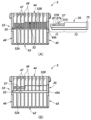
- a left wall 45 of the female housing 33 is formed with an opening 45A on the insertion side of the retainer insertion hole 51 into which the retainer 35 is inserted.
- the retainer insertion hole 51 extends laterally from the left wall 45 to the right wall 46 within the female housing 33 .
- the retainer insertion hole 51 is positioned substantially in the center of the female housing 33 in the vertical direction.
- the opening 45A formed in the left wall 45 has a substantially rectangular shape with rounded corners as shown in FIG.
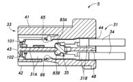
- the partition wall 48 is formed with a retainer opening 52 extending in the left-right direction so as to cut out the central portion thereof (see FIGS. 7(A) and 7(B)).
- the retainer opening 52 is formed through the left wall 45 and the right wall 46 and forms part of the retainer insertion hole 51 .
- the left and right edges of the retainer opening 52 are defined by a front side surface 52A and a rear side surface 52B extending generally in the left-right direction.
- a projection 55 (an example of a locking portion, hereinafter referred to as a housing projection 55) protruding forward from the rear side surface 52B is a projection 57 (an example of a locked portion, hereinafter, the retainer) formed on the retainer 35. (referred to as projection 57).
- the housing protrusion 55 has an inclined surface 55A, a parallel surface 55B, and a vertical surface 55C each having a rectangular shape.
- the inclined surface 55A has a left edge connected to the rear side surface 52B and extends right forward from the left edge (that is, obliquely to the rear side surface 52B).
- the parallel surface 55B continues to the right edge of the inclined surface 55A and extends rightward in parallel with the rear side surface 52B.
- the vertical surface 55C continues to the right edge of the parallel surface 55B and extends perpendicular to the rear side surface 52B, thereby connecting the right edge to the rear side surface 52B.
- the retainer opening 52 provided in the partition wall 48 (more precisely, the edge defining the opening) is formed with the housing projection 55 for locking the retainer projection 57, so that the female housing 33
- the holding strength of the retainer 35 against is stably ensured.
- the force acting to detach the retainer 35 acts along the substantially flat partition wall 48 (that is, imaginary plane), so the force acts in the direction orthogonal to the wall.
- the holding strength of the retainer 35 can be easily ensured (that is, the thickness of the wall is less likely to affect it).
- housing projections 55 are formed in the retainer openings 52 of the partition wall 48 , it is possible to avoid the influence of the formation of the housing projections 55 on the thickness of each wall constituting the female housing 33 .
- the housing protrusion 55 may protrude rearward from the front side surface 52A.
- a right wall 46 of the female housing 33 is formed with an opening 46A (see FIGS. 7(A) and 7(B)) through which the tip of the retainer 35 is exposed.
- the opening 46A of the right wall 46 may be omitted. That is, it is not essential that the retainer insertion hole 51 penetrate through the right wall 46 .
- the upper wall 41 of the female housing 33 is provided with a latched pawl 61 that is latched by a latching portion provided on the inner surface of the upper wall 15 of the male housing 13 .
- the locking portion provided on the inner surface side of the upper wall 15 may include an opening, a locking claw, or the like (not shown).
- the upper wall 41 is provided with an operation piece 63 (see FIG. 1) operated by the user. When fitting (ie, electrically connecting) the female housing 33 to the male housing 13 , the user presses the operating piece 63 downward to disengage the engaged claw 61 on the upper wall 41 .
- the periphery can be displaced inside (that is, below) the female housing 33 . As a result, the latched claw 61 is easily latched to the latching portion of the male housing 13 .
- a plurality of elastic locking claws 65 are provided at positions corresponding to the plurality of female terminals 31 on the upper wall 41 of the female housing 33 .
- the plurality of elastic locking claws 65 lock the plurality of female terminals 31 respectively inserted into the plurality of terminal housing chambers 47 constituting the first terminal housing chamber group 101, thereby preventing their rearward movement. regulate each. This prevents the female terminals 31 from coming off from the terminal accommodating chambers 47).
- Each elastic locking claw 65 is formed as an elastically deformable arm and can be displaced substantially in the vertical direction. When each female terminal 31 is in the normal housing position (that is, the female terminal 31 is completely inserted into the terminal housing chamber 47), each elastic locking claw 65 is attached to the bottom wall of the tubular portion 31A.
- each elastic locking claw 65 has the same configuration as each elastic locking claw 65, and is formed on the bottom wall of the cylindrical portion 31A when each female terminal 31 is in the normal accommodation position. inserted into the opening.
- the retainer 35 holds a plurality of female terminals 31 inserted into the terminal receiving chambers 47 of the female housing 33 . More specifically, the retainer 35 is inserted into the retainer insertion hole 51 of the female housing 33 and engages with each female terminal 31 in the normal accommodation position, thereby pushing each female terminal 31 rearward. Regulate movement.
- the retainer 35 can restrict rearward movement of all the female terminals 31 inserted into the first terminal receiving chamber group 101 and the second terminal receiving chamber group 102 . Thereby, the rearward movement of each female terminal 31 is doubly restricted by the elastic locking claws 65 and 66 of the female housing 33 and the retainer 35 .
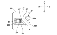
- the retainer 35 includes an insertion side portion 71 located on the insertion side of the female housing 33 in the left-right direction, and a base portion 73 connected to the rear of the insertion side portion 71. and a flange portion 75 formed at the rear end of the base portion 73 .
- the retainer 35 can be divided into a front portion 81 and a rear portion 82 in the front-rear direction.
- the rear portion 82 of the insertion side portion 71 has a convex shape that protrudes rearward in a cross section perpendicular to the left-right direction. That is, the rear side of the rear portion 82 of the insertion side portion 71 (that is, the convex distal end side) is configured to have a narrower vertical width than the front side.
- the rear portion 82 of the insertion side portion 71 includes a rear surface 82A extending substantially along the left-right direction so as to be orthogonal to the front-rear direction.
- the retainer 35 is provided with a retainer projection 57 projecting rearward from the rear surface 82A.
- Retainer projections 57 are locked to housing projections 55 .
- the retainer protrusion 57 has an inclined surface 57A, a parallel surface 57B, and a vertical surface 57C each having a rectangular shape.
- the slanted surface 57A has its right edge connected to the rear surface 82A and extends from that right edge to the rear left (that is, diagonally with respect to the rear surface 82A).
- the parallel surface 57B continues to the left edge (that is, rearward in the insertion direction) of the inclined surface 57A and extends leftward in parallel with the rear surface 82A.
- the vertical surface 57C continues to the left edge of the parallel surface 57B and extends perpendicular to the rear surface 82A, thereby connecting the left edge to the rear surface 82A.
- a long hole 87 is provided inside (that is, in front of) the retainer projection 57 so as to penetrate the rear side (that is, narrow width portion) of the rear portion 82 in the vertical direction.
- the portion between the retainer projection 57 and the elongated hole 87 functions as an elastic deformation portion 89 that elastically deforms when the retainer projection 57 is engaged with the housing projection 55 .
- the elastically deformable portion 89 is provided on the rear side of the rear portion 82 having a convex shape. Less than the maximum directional width.
- a cover piece 88 arranged to cover the long hole 87 is provided below the long hole 87 in the rear portion 82 of the insertion side portion 71 (see FIG. 5(B)).
- a rear edge 88A of the cover piece 88 is located forward of a rear surface 82A of the rear portion 82.
- the rear edge 88A of the cover piece 88 is partially cut into the inner wall 49 (that is, the notch 59A of the inner wall 49 defining the retainer insertion hole 51 (FIG. 7A). ) see)).
- the retainer 35 can more stably prevent the female terminal 31 from being detached from the female housing 33 .
- one opening of the long hole 87 is covered with a cover piece 88 .
- the female terminals 31 inserted into the terminal accommodating chambers 47 in the first terminal accommodating chamber group 101 and positioned near the elongated holes 87 and the female terminals 31 inserted into the terminal accommodating chambers 47 in the second terminal accommodating chamber group 102 In addition, it is possible to prevent an unintended electrical connection (that is, a short circuit) between the female terminal 31 located near the elongated hole 87 and the elongated hole 87 in the penetrating direction.
- the cover piece 88 may be provided above (or above and below) the long hole 87. As shown in FIG.
- a front portion 81 of the insertion side portion 71 includes a first terminal locking portion 83A projecting upward and forward from the rear portion 82 and a terminal receiving chamber extending from the rear portion 82 when viewed from the left and right direction of the retainer 35 (see FIG. 6). and a second terminal locking portion 83B protruding forward and downward on the 47 side.
- the first terminal locking portion 83A locks the plurality of female terminals 31 respectively inserted into the plurality of terminal housing chambers 47 constituting the first terminal housing chamber group 101, thereby preventing the rearward movement thereof. regulate each.
- the second terminal locking portion 83B locks the plurality of female terminals 31 respectively inserted into the plurality of terminal housing chambers 47 constituting the second terminal housing chamber group 102, thereby preventing the rearward movement thereof. regulate each.
- the front portion 81 on the base 73 has a similar shape to the front portion 81 on the insertion side 71 (i.e., the front portion 81 has a similar shape from the insertion side 71 to the base 73), and the first terminal It includes a locking portion 83A and a second terminal locking portion 83B.
- the rear portion 82 of the base portion 73 is located to the left of the rear portion 82 of the insertion side portion 71 (that is, rearward in the insertion direction).
- a rear surface 82B (see FIG. 5B) of the base portion 73 extends in the left-right direction so as to be orthogonal to the front-rear direction, and is positioned further rearward than the rear surface 82A of the rear portion 82 of the insertion side portion 71 .
- a rear portion 82 of the base portion 73 has a substantially rectangular parallelepiped shape.
- the insertion side portion 71 including the retainer protrusion 57 has a width in the front-rear direction narrower than that of the base portion 73 in plan view.
- the retainer protrusion 57 is provided as a portion to be engaged of the retainer 35 to be engaged with the female housing 33, an increase in the width of the retainer 35 in the front-rear direction is suppressed, and the retainer 35 is attached at the base portion 73 to the female housing. 33 can be secured in the front-rear direction width necessary for stably holding it.
- the front-rear width of the insertion side portion 71 including the retainer projection 57 in plan view may be set larger than the front-rear width of the base portion 73 as necessary.
- the flange portion 75 can be fitted into the opening 45A of the female housing 33, and its outer edge forms a substantially rectangular shape with rounded corners.
- a user inserts the retainer 35 into the retainer insertion hole 51 by moving it rightward from the state shown in FIGS. 7(A) and 8(A). Thereby, the retainer 35 is attached to the retainer insertion hole 51 as shown in FIGS. 7B and 8B.
- the inclined surface 57A of the retainer projection 57 contacts the inclined surface 55A of the housing projection 55 .
- the retainer projection 57 is displaced inward (that is, forward) and moves to the right of the housing projection 55 so as to overcome the housing projection 55 .
- the vertical surface 57C of the retainer projection 57 comes into contact with the vertical surface 55C of the housing projection 55, and the leftward movement of the retainer 35 is restricted. This prevents the retainer 35 from being detached from the retainer insertion hole 51 .
- the width of the retainer opening 52 forming the retainer insertion hole 51 in the front-rear direction (that is, the distance between the front side surface 52A and the rear side surface 52B excluding the housing protrusion 55) is At a portion corresponding to the side portion 71 (that is, a portion located on the right side), the width in the front-rear direction of the insertion side portion 71 of the retainer 35 including the retainer projection 57 is substantially the same as or wider than the width in the front-rear direction of the insertion side portion 71 . is also slightly larger.
- the longitudinal width of the retainer opening 52 greater than the longitudinal width of the portion corresponding to the insertion side portion 71 at the portions corresponding to the base portion 73 of the retainer 35 (that is, the portions located at the center and the left side)? , or the front-rear direction width of the portion corresponding to the insertion side portion 71 . Accordingly, insertion of the retainer 35 into the retainer insertion hole 51 is not hindered until the inclined surface 57A of the retainer projection 57 contacts the inclined surface 55A of the housing projection 55. As shown in FIG.
- each inner wall 49 of the female housing 33 has notches 59A formed to correspond to the cross-sectional shape of the retainer 35 at portions corresponding to the retainer insertion holes 51. 59B.
- a notch portion 59A of the inner wall 49 forming the portion of the retainer insertion hole 51 corresponding to the insertion side portion 71 of the retainer 35 is cut away from a notch portion 59B of the inner wall 49 forming the portion of the retainer insertion hole 51 corresponding to the base portion 73.
- the retainer 35 having a smaller width in the front-rear direction can be provided.
- the insertion side portion 71 and the base portion 73 of the retainer having a larger width in the front-rear direction can be held stably.
- the cylindrical portions 31A of the female terminals 31 are inserted into the terminal accommodating chambers 47 constituting the first terminal accommodating chamber group 101.
- the first terminal locking portion 83A of the retainer 35 abuts against the rear end of the female terminal 31, thereby preventing the female terminal 31 from moving rearward (that is, separating from the terminal accommodating chamber 47).
- the second terminal locking portion 83B of the retainer 35 abuts against the rear end of the cylindrical portion 31A of the female terminal 31 inserted into the terminal receiving chamber 47 constituting the second terminal receiving chamber group 102. Rearward movement of the female terminal 31 is prevented.
Landscapes
- Connector Housings Or Holding Contact Members (AREA)
Priority Applications (4)
| Application Number | Priority Date | Filing Date | Title |
|---|---|---|---|
| US18/715,437 US20250316922A1 (en) | 2021-12-03 | 2022-11-24 | Electric connector and pair of electric connectors |
| CN202280076908.3A CN118266135A (zh) | 2021-12-03 | 2022-11-24 | 电连接器和一对电连接器 |
| EP22901163.0A EP4443664A4 (en) | 2021-12-03 | 2022-11-24 | ELECTRIC CONNECTOR AND ELECTRIC CONNECTOR PAIR SO THAT |
| JP2023564909A JP7541625B2 (ja) | 2021-12-03 | 2022-11-24 | 電気コネクタ及びこれを備えた電気コネクタ対 |
Applications Claiming Priority (2)
| Application Number | Priority Date | Filing Date | Title |
|---|---|---|---|
| JP2021-197248 | 2021-12-03 | ||
| JP2021197248 | 2021-12-03 |
Publications (1)
| Publication Number | Publication Date |
|---|---|
| WO2023100730A1 true WO2023100730A1 (ja) | 2023-06-08 |
Family
ID=86612078
Family Applications (1)
| Application Number | Title | Priority Date | Filing Date |
|---|---|---|---|
| PCT/JP2022/043281 Ceased WO2023100730A1 (ja) | 2021-12-03 | 2022-11-24 | 電気コネクタ及びこれを備えた電気コネクタ対 |
Country Status (5)
| Country | Link |
|---|---|
| US (1) | US20250316922A1 (https=) |
| EP (1) | EP4443664A4 (https=) |
| JP (1) | JP7541625B2 (https=) |
| CN (1) | CN118266135A (https=) |
| WO (1) | WO2023100730A1 (https=) |
Citations (6)
| Publication number | Priority date | Publication date | Assignee | Title |
|---|---|---|---|---|
| JPS6240782U (https=) * | 1985-08-29 | 1987-03-11 | ||
| JPH0397875U (https=) | 1990-01-26 | 1991-10-09 | ||
| JPH1116625A (ja) | 1997-06-20 | 1999-01-22 | Yazaki Corp | コネクタの二重係止部材 |
| JP2001167835A (ja) * | 1999-12-13 | 2001-06-22 | Sumitomo Wiring Syst Ltd | コネクタ |
| JP2006190696A (ja) * | 2006-04-07 | 2006-07-20 | Sumitomo Wiring Syst Ltd | コネクタ |
| JP2015133216A (ja) | 2014-01-10 | 2015-07-23 | 第一精工株式会社 | 電気コネクタ |
Family Cites Families (1)
| Publication number | Priority date | Publication date | Assignee | Title |
|---|---|---|---|---|
| JP3852648B2 (ja) * | 1998-12-09 | 2006-12-06 | 住友電装株式会社 | コネクタ |
-
2022
- 2022-11-24 WO PCT/JP2022/043281 patent/WO2023100730A1/ja not_active Ceased
- 2022-11-24 JP JP2023564909A patent/JP7541625B2/ja active Active
- 2022-11-24 US US18/715,437 patent/US20250316922A1/en active Pending
- 2022-11-24 CN CN202280076908.3A patent/CN118266135A/zh active Pending
- 2022-11-24 EP EP22901163.0A patent/EP4443664A4/en active Pending
Patent Citations (6)
| Publication number | Priority date | Publication date | Assignee | Title |
|---|---|---|---|---|
| JPS6240782U (https=) * | 1985-08-29 | 1987-03-11 | ||
| JPH0397875U (https=) | 1990-01-26 | 1991-10-09 | ||
| JPH1116625A (ja) | 1997-06-20 | 1999-01-22 | Yazaki Corp | コネクタの二重係止部材 |
| JP2001167835A (ja) * | 1999-12-13 | 2001-06-22 | Sumitomo Wiring Syst Ltd | コネクタ |
| JP2006190696A (ja) * | 2006-04-07 | 2006-07-20 | Sumitomo Wiring Syst Ltd | コネクタ |
| JP2015133216A (ja) | 2014-01-10 | 2015-07-23 | 第一精工株式会社 | 電気コネクタ |
Non-Patent Citations (1)
| Title |
|---|
| See also references of EP4443664A4 |
Also Published As
| Publication number | Publication date |
|---|---|
| JPWO2023100730A1 (https=) | 2023-06-08 |
| EP4443664A4 (en) | 2025-12-17 |
| JP7541625B2 (ja) | 2024-08-28 |
| EP4443664A1 (en) | 2024-10-09 |
| US20250316922A1 (en) | 2025-10-09 |
| CN118266135A (zh) | 2024-06-28 |
Similar Documents
| Publication | Publication Date | Title |
|---|---|---|
| JP5059571B2 (ja) | 基板用雌端子金具 | |
| JP5582893B2 (ja) | 面実装用マルチコネクタ及び電子機器 | |
| US8100709B2 (en) | Electrical connector having improved latching members | |
| JP2013137921A (ja) | 電気コネクタ | |
| US10811812B2 (en) | Waterproof connector including rear holder for holding wires and preventing waterproof member from detaching from housing | |
| CN114498156A (zh) | 连接器 | |
| JP2008538851A (ja) | ターミナル位置保証機構を備えた電気コネクタ | |
| JP2004095346A (ja) | コネクタ組立体及びそれに使用するコネクタ | |
| CN112350092A (zh) | 连接器及端子 | |
| JP2011108576A (ja) | ホルダ付コネクタ | |
| CN107492730B (zh) | 连接器用端子保持部件、连接器和电连接装置 | |
| WO2023100730A1 (ja) | 電気コネクタ及びこれを備えた電気コネクタ対 | |
| JP2020161323A (ja) | コネクタハウジング | |
| JP5183315B2 (ja) | コネクタ | |
| JP7603137B2 (ja) | 電気コネクタ及びこれを備えた電気コネクタ対 | |
| CN112952410B (zh) | 连接器 | |
| JP2022149024A5 (https=) | ||
| US20250149820A1 (en) | Connector device | |
| US20240204454A1 (en) | Connector | |
| JP2003249313A (ja) | 分割コネクタ | |
| JP2024017399A (ja) | ハウジングユニット | |
| JP2024041230A (ja) | コネクタ | |
| JP2024167955A (ja) | コネクタ | |
| JP2025024347A (ja) | コネクタ | |
| JP2024126303A (ja) | コネクタ |
Legal Events
| Date | Code | Title | Description |
|---|---|---|---|
| 121 | Ep: the epo has been informed by wipo that ep was designated in this application |
Ref document number: 22901163 Country of ref document: EP Kind code of ref document: A1 |
|
| WWE | Wipo information: entry into national phase |
Ref document number: 2023564909 Country of ref document: JP |
|
| WWE | Wipo information: entry into national phase |
Ref document number: 202280076908.3 Country of ref document: CN |
|
| WWE | Wipo information: entry into national phase |
Ref document number: 202447048606 Country of ref document: IN |
|
| WWE | Wipo information: entry into national phase |
Ref document number: 2022901163 Country of ref document: EP |
|
| NENP | Non-entry into the national phase |
Ref country code: DE |
|
| ENP | Entry into the national phase |
Ref document number: 2022901163 Country of ref document: EP Effective date: 20240703 |
|
| WWP | Wipo information: published in national office |
Ref document number: 18715437 Country of ref document: US |