WO2023100686A1 - ガラス板の製造方法 - Google Patents
ガラス板の製造方法 Download PDFInfo
- Publication number
- WO2023100686A1 WO2023100686A1 PCT/JP2022/042814 JP2022042814W WO2023100686A1 WO 2023100686 A1 WO2023100686 A1 WO 2023100686A1 JP 2022042814 W JP2022042814 W JP 2022042814W WO 2023100686 A1 WO2023100686 A1 WO 2023100686A1
- Authority
- WO
- WIPO (PCT)
- Prior art keywords
- glass plate
- etching
- etching step
- etchant
- main surface
- Prior art date
- Legal status (The legal status is an assumption and is not a legal conclusion. Google has not performed a legal analysis and makes no representation as to the accuracy of the status listed.)
- Ceased
Links
Images







Classifications
-
- C—CHEMISTRY; METALLURGY
- C03—GLASS; MINERAL OR SLAG WOOL
- C03C—CHEMICAL COMPOSITION OF GLASSES, GLAZES OR VITREOUS ENAMELS; SURFACE TREATMENT OF GLASS; SURFACE TREATMENT OF FIBRES OR FILAMENTS MADE FROM GLASS, MINERALS OR SLAGS; JOINING GLASS TO GLASS OR OTHER MATERIALS
- C03C15/00—Surface treatment of glass, not in the form of fibres or filaments, by etching
-
- B—PERFORMING OPERATIONS; TRANSPORTING
- B23—MACHINE TOOLS; METAL-WORKING NOT OTHERWISE PROVIDED FOR
- B23K—SOLDERING OR UNSOLDERING; WELDING; CLADDING OR PLATING BY SOLDERING OR WELDING; CUTTING BY APPLYING HEAT LOCALLY, e.g. FLAME CUTTING; WORKING BY LASER BEAM
- B23K26/00—Working by laser beam, e.g. welding, cutting or boring
- B23K26/50—Working by transmitting the laser beam through or within the workpiece
- B23K26/53—Working by transmitting the laser beam through or within the workpiece for modifying or reforming the material inside the workpiece, e.g. for producing break initiation cracks
-
- C—CHEMISTRY; METALLURGY
- C03—GLASS; MINERAL OR SLAG WOOL
- C03B—MANUFACTURE, SHAPING, OR SUPPLEMENTARY PROCESSES
- C03B33/00—Severing cooled glass
- C03B33/09—Severing cooled glass by thermal shock
-
- C—CHEMISTRY; METALLURGY
- C03—GLASS; MINERAL OR SLAG WOOL
- C03C—CHEMICAL COMPOSITION OF GLASSES, GLAZES OR VITREOUS ENAMELS; SURFACE TREATMENT OF GLASS; SURFACE TREATMENT OF FIBRES OR FILAMENTS MADE FROM GLASS, MINERALS OR SLAGS; JOINING GLASS TO GLASS OR OTHER MATERIALS
- C03C23/00—Other surface treatment of glass not in the form of fibres or filaments
- C03C23/0005—Other surface treatment of glass not in the form of fibres or filaments by irradiation
- C03C23/0025—Other surface treatment of glass not in the form of fibres or filaments by irradiation by a laser beam
-
- H—ELECTRICITY
- H10—SEMICONDUCTOR DEVICES; ELECTRIC SOLID-STATE DEVICES NOT OTHERWISE PROVIDED FOR
- H10P—GENERIC PROCESSES OR APPARATUS FOR THE MANUFACTURE OR TREATMENT OF DEVICES COVERED BY CLASS H10
- H10P50/00—Etching of wafers, substrates or parts of devices
- H10P50/60—Wet etching
- H10P50/64—Wet etching of semiconductor materials
- H10P50/642—Chemical etching
Definitions
- the present invention relates to a method for manufacturing a glass plate having through holes.
- glass plates with fine through holes for wiring are used as substrates for tiling displays (micro LEDs, etc.), bezelless displays, and glass interposers.
- a method for manufacturing a glass plate having through holes of this type includes, for example, a reforming step of forming a reformed portion by reforming the intended formation position of the through hole in the glass plate by irradiating a laser beam; and an etching step of etching a portion to be formed to form a through hole (see, for example, Patent Documents 1 and 2).
- the modified portion formed in the modifying step has a higher etching rate than the unmodified portion, and is selectively removed in the etching step. Therefore, by forming the modified portion from the first main surface to the second main surface along the plate thickness direction of the glass plate, the through hole can be formed by etching.
- the through-hole When the through-hole is formed in this way, the portion closer to the main surface of the glass plate is more likely to be etched because it is in contact with the etchant for a longer time. , and the inner wall surface of the through hole becomes tapered. If the hole diameter on the main surface of the glass plate becomes large in this way, problems may occur such as a high-definition pattern being unable to be formed on the main surface of the glass plate.
- the angle of inclination of the inner wall surface of the through hole with respect to the direction perpendicular to the thickness direction is the etching condition. change depending on
- An object of the present invention is to increase the inclination angle of the inner wall surface of the through hole.
- the present invention invented to solve the above problems, has a first main surface, a second main surface, and a through hole penetrating between the first main surface and the second main surface.
- a method for manufacturing a glass plate comprising: a modification step of modifying a portion where a through-hole is to be formed by irradiating a laser beam; an etching step of forming a through-hole in the planned portion, wherein the etching step is performed after the first etching step of etching the glass plate through which the planned formation portion does not penetrate; and a second etching step for etching the penetrating glass plate, wherein the average relative velocity of the etchant to the glass plate is made faster in the second etching step than in the first etching step.
- the inventors of the present invention have found that the inclination angle of the inner wall surface of the through hole that is finally formed is: , (b) is determined by the change speed of the inclination angle of the inner wall surface of the planned formation portion after the formation planned portion penetrates. That is, in order to increase the angle of inclination of the finally formed through-hole, (a') increase the angle of inclination of the inner wall surface of the part to be formed when the part to be formed penetrates (close to 90°). (b') It is important to change the change speed of the inclination angle of the inner wall surface of the planned formation portion after the penetration of the formation planned portion in the positive direction.
- the part to be formed that has been modified by laser irradiation is in a state of being easily etched.
- the etchant cannot move inside the planned formation portion in the plate thickness direction. Therefore, even if the average relative velocity of the etchant with respect to the glass plate is increased in this state, the exchange efficiency of the etchant in the concave portion of the portion to be formed does not increase as compared to the exchange efficiency of the etchant in the main surface of the glass plate. .
- the time required for the replacement of the etchant is not shorter in the concave portion of the intended formation portion than in the main surface of the glass plate.
- etching is promoted only in the vicinity of the main surface of the glass plate, and the pore diameter of the main surface is preferentially enlarged.
- the inclination angle of the inner wall surface of the portion to be formed at the time of penetration is reduced.
- the etchant can flow in the plate thickness direction inside the formation planned portion.
- the exchange efficiency of the etchant inside the portion to be formed increases as well as the exchange efficiency of the etchant on the main surface of the glass plate.
- the rate of change of the inclination angle of the inner wall surface of the portion to be formed after penetration can be changed in the positive direction. Therefore, if the average relative velocity of the etchant with respect to the glass plate is made higher in the second etching step than in the first etching step as in the above configuration, the inner wall surface of the portion to be formed when the portion to be formed penetrates.
- the progress rate of etching in the formation-planned portion can be increased from the time when the formation-planned portion penetrates. Therefore, it is possible to change the change speed of the inclination angle of the inner wall surface of the part to be formed after the part to be formed penetrates in a more positive direction. Thereby, the inclination angle of the inner wall surface of the through hole can be increased.
- the etching solution in the etching step, may be stirred, and the average stirring speed of the etching solution may be faster in the second etching step than in the first etching step.
- the average relative velocity of the etchant to the glass plate can be made faster in the second etching process than in the first etching process.
- the average relative velocity of the etchant to the glass plate can be made faster in the second etching process than in the first etching process.
- the present invention invented to solve the above problems, has a first principal surface, a second principal surface, and a through hole penetrating between the first principal surface and the second principal surface.
- a method for manufacturing a glass plate comprising: a modifying step of modifying a portion where a through hole is to be formed by irradiating a laser beam; an etching step of forming a through-hole in the portion to be formed by spraying and etching, wherein the etching step includes a first etching step of etching the glass plate through which the portion to be formed does not penetrate, and a first etching step. and a second etching step of etching the glass plate through which the part to be formed penetrates, wherein the average injection pressure of the etchant against the glass plate is higher in the second etching step than in the first etching step.
- the average injection pressure of the etchant sprayed onto the glass plate is increased in the second etching process than in the first etching process, it is possible to prevent the penetration of the part to be formed.
- the change speed of the inclination angle of the inner wall surface of the part to be formed after the part to be formed penetrates can be changed in the positive direction. Thereby, the inclination angle of the inner wall surface of the through hole can be increased.
- the inclination angle of the inner wall surface of the through hole can be increased more reliably.
- the inclination angle of the inner wall surface of the through hole can be increased.
- the method for manufacturing a glass plate according to the first embodiment includes, in this order, a modification step S1 and an etching step S2 including a first etching step S2a and a second etching step S2b.
- the modification step S1 is a step of modifying the portion 3 of the glass plate 2 where the through hole is to be formed by the laser beam L emitted from the laser device 1.
- the reformed formation scheduled portion 3 includes a reformed portion 4 extending in the plate thickness direction.
- the modified portion 4 has a property of being easily etched, and has a higher etching rate than the non-modified portion.
- the reformed portion 4 is preferably formed continuously in the plate thickness direction, but may be intermittently formed in the plate thickness direction.
- the type and irradiation conditions of the laser beam L are not particularly limited as long as the modified portion 4 can be formed in the through-hole formation scheduled portion 3 of the glass plate 2 .
- the laser light L is short pulse laser light (picosecond laser light, nanosecond laser light, femtosecond laser light).
- the diameter W of the modified portion 4 can be adjusted by the spot diameter of the laser beam L or the like.
- the glass plate 2 is etched to form the first main surface 2a and the second main surface of the glass plate 2 in the formation scheduled portion 3 including the modified portion 4. 2b in the plate thickness direction.
- the glass plate 2 is immersed in the etchant 6 stored in the etching vessel 5, and etching is simultaneously progressed from both sides of the first main surface 2a and the second main surface 2b of the glass plate 2.
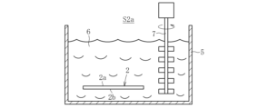
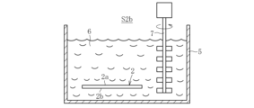
- the etching step S2 is performed after the first etching step S2a (see FIG. 3) of etching the glass plate 2 through which the planned formation portion 3 does not penetrate (see FIG. 3) and the first etching step S2a. and a second etching step S2b (see FIG. 4) for etching the glass plate 2 through which 3 passes.
- the same etching vessel 5 in which the etching liquid 6 is stored is used.
- the etching container used in the first etching step S2a may be different from the etching container used in the second etching step S2b.
- the average relative velocity of the etchant 6 with respect to the glass plate 2 in the second etching step S2b (hereinafter referred to as the second average relative velocity) V2 is the average relative velocity of the etchant 6 with respect to the glass plate 2 in the first etching step S2a (hereinafter referred to as faster than V1 (referred to as the first average relative velocity).
- Examples of methods for making the second average relative speed V2 faster than the first average relative speed V1 include a method of stirring the etching liquid 6 and a method of moving the glass plate 2 in the etching liquid 6.
- a method of stirring the etchant 6 and a method of moving the glass plate 2 in the etchant 6 may be used in combination. .
- Methods for stirring the etching solution 6 include, for example, a method of swinging a louver and a method of vibrating the etching solution 6 with ultrasonic waves. A rotating method is used.
- the stirring member 7 is arranged on the side of the glass plate 2, but the arrangement position of the stirring member 7 is not particularly limited. The stirring member 7 may be arranged below the glass plate 2 or may be arranged above the glass plate.
- the average stirring speed of the etching solution 6 in the second etching step S2b (referred to as the second average stirring speed) is set to , the average stirring speed of the etchant 6 in the first etching step S2a (referred to as the first average stirring speed).
- the average stirring speed means the average rotation speed of the stirring member 7 when the stirring member 7 is used.
- the arrangement position of the stirring member 7 is not particularly limited.
- Examples of the method of moving the glass plate 2 in the etching solution 6 include a method of swinging the glass plate 2 in the etching solution 6, a method of rotating the glass plate 2 in the etching solution 6, and the like.
- the average moving speed of the glass plate 2 in the second etching step S2b (second average moving speed) is preferably faster than the average moving speed of the glass plate 2 in the first etching step S2a (referred to as the first average moving speed).
- the second etching step S2b is started when the part to be formed 3 penetrates in the plate thickness direction. That is, when the formation scheduled portion 3 penetrates in the plate thickness direction, the average relative velocity of the etchant 6 with respect to the glass plate 2 is switched from the first average relative velocity V1 to the second average relative velocity V2.
- the etching time for the planned formation portion 3 to penetrate is measured in advance under the same etching conditions, and when the measured time elapses, it is assumed that the formation planned portion 3 has penetrated, and the second etching step S2b is performed. Start. A camera or the like may be used to observe in real time when the planned formation portion 3 penetrates, and the second etching step S2b may be started at the time when the formation planned portion 3 is observed to penetrate.
- the formation-scheduled portion 3 including the modified portion 4 is gradually removed by etching.
- the portion to be formed 3 does not penetrate but forms a recess 8 with a bottom.
- the etchant 6 cannot pass through the inside of the formation scheduled portion 3 in the plate thickness direction. Therefore, even if the first average relative velocity V1 is increased, the exchange efficiency of the etchant 6 in the concave portion 8 of the portion to be formed 3 does not increase.
- the etchant 6 in the concave portion 8 of the portion to be formed 3 is gradually contaminated with a reaction product (sludge). Therefore, when the etching rate of the portion to be formed 3 is R1 and the etching rate of the main surfaces 2a and 2b is R2, the ratio of R1/R2 decreases. As a result, etching is promoted only in the vicinity of the main surfaces 2a and 2b of the glass plate 2, and the inclination angle (also referred to as taper angle) ⁇ 1 (see FIG. 6) of the inner wall surface 3a of the portion to be formed 3 at the time of penetration is reduced. end up
- the part to be formed 3 is in a penetrating state.
- the etchant 6 can freely move inside the formation-planned portion 3 in the plate thickness direction. Therefore, if the second average relative velocity V2 is increased, the exchange efficiency of the etchant 6 inside the formation-planned portion 3 is increased as well as the exchange efficiency of the etchant 6 on the main surfaces 2a and 2b of the glass plate 2 .
- the etching of the portion to be formed 3 is promoted in the same manner as the etching of the vicinity of the main surfaces 2a and 2b of the glass plate 2 is promoted.
- the change in the inclination angle ⁇ 1 of the inner wall surface 3a of the portion to be formed 3 after penetration can be reduced, and the etching time required to obtain a desired hole diameter can be shortened.
- the second average relative velocity V2 in the second etching step S2b is made faster than the first average relative velocity V1 in the first etching step S2a.
- (1) the inclination angle ⁇ 1 of the inner wall surface 3a of the formation planned portion 3 when the formation planned portion 3 penetrates is increased, and (2) the formation after the formation planned portion 3 penetrates.
- the change speed of the inclination angle ⁇ 1 of the inner wall surface 3a of the planned portion 3 can be changed in the positive direction.
- the inclination angle (also referred to as taper angle) ⁇ 2 of the inner wall surface 9a of the through hole 9 finally formed in the glass plate 2 can be increased.
- the hole diameter at the central portion of the through hole 9 in the plate thickness direction is the minimum hole diameter D1
- the hole diameter at the main surfaces 2a and 2b of the through hole 9 is the maximum hole diameter D2.
- the method for manufacturing a glass plate according to the second embodiment differs from the method for manufacturing a glass plate according to the first embodiment in that, in the etching step S2, the glass immersed in the etchant 6 is This is the point of conveying the plate 2 .
- the etchant 6 is stored in the etching container 10 elongated in the direction in which the glass plate 2 is conveyed.
- the glass plate 2 is transported by a transporting device 11 such as a roller while being immersed in the etchant 6 .
- the first etching step S2a is performed in the first area 12 on the upstream side in the transport direction of the position where the planned formation portion 3 penetrates, and the position and the transport direction where the planned formation portion 3 penetrates.
- the second etching step S2b is performed in the second area 13 including the downstream side of the . That is, the average relative velocity of the etchant 6 with respect to the glass plate 2 is a relatively small first average relative velocity V1 in the first area 12, and a relatively large second average relative velocity V2 in the second area 13. be.
- the average stirring speed of the stirring members 7b in the second area 13 may be higher than the average stirring speed of the stirring members 7a in the first area 12.
- the average moving speed of the glass plate 2 by the conveying device 11 in the second area 13 may be faster than the average moving speed of the glass plate 2 by the conveying device 11 in the first area 12 .
- a partition wall 14 is provided between the first area 12 and the second area 13 to suppress the movement of the etchant 6 between the two areas.
- the areas 12 and 13 are partitioned by the partition wall 14, so that the average relative velocity of the etchant 6 with respect to the glass plate 2 can be easily adjusted in each of the areas 12 and 13 individually.
- the partition wall 14 may be omitted.
- the glass plate manufacturing method according to the third embodiment differs from the glass plate manufacturing methods according to the first and second embodiments in that, in the etching step S2, the glass plate 2 is immersed in the etchant 6, the etchant 6 is sprayed onto the first main surface 2a and the second main surface 2b of the glass plate 2.
- FIG. 9 the glass plate manufacturing method according to the third embodiment differs from the glass plate manufacturing methods according to the first and second embodiments in that, in the etching step S2, the glass plate 2 is immersed in the etchant 6, the etchant 6 is sprayed onto the first main surface 2a and the second main surface 2b of the glass plate 2.
- the etching step S2 is the first etching in which the etchant 6 is jetted from the nozzle 15 to the first main surface 2a and the second main surface 2b of the glass plate 2 through which the intended formation portion 3 does not penetrate.
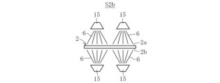
- the etchant 6 is sprayed from the nozzle 15 onto the first main surface 2a and the second main surface 2b of the glass plate 2 through which the part to be formed 3 penetrates. and a second etching step S2b (see FIG. 10) for performing etching.
- the average injection pressure of the etching solution 6 onto the glass plate 2 in the second etching step S2b (hereinafter referred to as the second average injection pressure) Q2 is the average injection pressure of the etching solution 6 onto the glass plate 2 in the first etching step S2a (hereinafter referred to as higher than Q1 (referred to as the first average injection pressure).
- the second etching step S2b is started when the part to be formed 3 penetrates in the plate thickness direction. That is, when the formation scheduled portion 3 penetrates in the plate thickness direction, the average injection pressure of the etchant 6 against the glass plate 2 is switched from the first average injection pressure Q1 to the second average injection pressure Q2.
- the method for manufacturing a glass plate according to the fourth embodiment differs from the method for manufacturing a glass plate according to the third embodiment in that, in the etching step S2, the conveyed glass plate 2 is The point is that the etchant 6 is sprayed on the substrate.
- the glass plate 2 is transported downstream in the transport direction by the transport device 16 .
- the etchant 6 is sprayed from the nozzles 15a and 15b onto the first main surface 2a and the second main surface 2b of the glass plate 2, respectively.
- the first etching step S2a is performed in the first area 17 on the upstream side of the position where the planned formation portion 3 penetrates, and the first etching step S2a including the position where the formation planned portion 3 penetrates and the downstream side thereof.
- a second etching step S2b is performed in the second area 18 . That is, the average injection pressure of the etchant 6 against the glass plate 2 is a relatively low first average injection pressure Q1 in the first area 17, and a relatively high second average injection pressure Q2 in the second area 18. be.
- the amount of the etchant 6 sprayed per unit time from the nozzle 15b of the second area 18 is made larger than the amount of the etchant 6 sprayed per unit time from the nozzle 15a of the first area 17. good too.
- the number of nozzles 15 b in the second area 18 may be relatively increased compared to the number of nozzles 15 a in the first area 17 .
- the second etching step S2b may be started before the formation scheduled portion 3 is penetrated (for example, several minutes before the penetration). Alternatively, the second etching step S2b may be started after the formation scheduled portion 3 is penetrated (for example, several minutes after the penetration).
- the start timing of the second etching step S2b is not particularly limited as long as it includes a step of etching the glass plate 2 through which the portion to be formed 3 penetrates.
- the second etching step S2b may be started when the formation scheduled portion 3 penetrates. preferable.
- the glass plates 2 may be etched one by one, or a plurality of glass plates 2 may be etched simultaneously. Further, in the etching step S2, when the glass plate 2 is etched while being conveyed, the conveying path of the glass plate 2 is not limited to a straight line, and may be curved such as an annular shape.
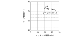
- the point indicated by symbol P in the figure is the taper angle of the planned formation portion when the planned formation portion penetrates.
- the taper angle of the portion to be formed at the time of penetration changes according to the rate of change of the taper angle (-0.07°/min in the figure) and the etching time until the through hole is finally formed. ing. That is, the taper angle of the through-hole includes (1) the taper angle of the planned formation portion when the planned formation portion penetrates, (2) the change rate of the taper angle of the planned formation portion after the planned formation portion penetrates, and (3) Determined by etching time.
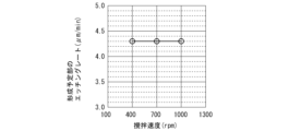
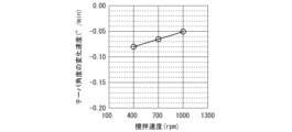
- FIGS. 13 to 16 show how the average relative velocity of the etchant to the glass plate affects the taper angle of the through-holes formed in the glass plate. The results are shown in FIGS. 13 to 16.
- FIG. Adjustment of the average relative velocity of the etchant to the glass plate was performed by stirring the etchant using a water bath stirrer.
- a water bath stirrer is a device that uses magnetic force to rotate a stirrer to stir a liquid such as an etchant.
- the etching rate of the main surface of the glass plate increases as the stirring speed of the etchant increases.
- the etching rate of the formation planned portion does not substantially change even if the stirring speed of the etchant increases.
- the taper angle of the formation planned portion when the formation planned portion penetrates becomes smaller as the stirring speed of the etchant increases.
- the rate of change of the taper angle of the portion to be formed after the portion to be formed changes in the positive direction as the stirring speed of the etchant increases. From this result, it can be seen that by increasing the stirring speed of the etchant after the portion to be formed penetrates, the angle change from the taper angle of the portion to be formed when the portion to be formed penetrates can be changed in the positive direction. Therefore, it can be said that it is preferable to increase the average relative velocity of the etchant with respect to the glass plate after the portion to be formed penetrates.
Landscapes
- Chemical & Material Sciences (AREA)
- Engineering & Computer Science (AREA)
- Physics & Mathematics (AREA)
- General Chemical & Material Sciences (AREA)
- Chemical Kinetics & Catalysis (AREA)
- Organic Chemistry (AREA)
- Materials Engineering (AREA)
- Optics & Photonics (AREA)
- Life Sciences & Earth Sciences (AREA)
- Geochemistry & Mineralogy (AREA)
- Toxicology (AREA)
- Health & Medical Sciences (AREA)
- Oil, Petroleum & Natural Gas (AREA)
- Plasma & Fusion (AREA)
- Mechanical Engineering (AREA)
- Thermal Sciences (AREA)
- Surface Treatment Of Glass (AREA)
- Re-Forming, After-Treatment, Cutting And Transporting Of Glass Products (AREA)
Abstract
Description
図1に示すように、第一実施形態に係るガラス板の製造方法は、改質工程S1と、第一エッチング工程S2a及び第二エッチング工程S2bを含むエッチング工程S2とをこの順に備える。
図8に示すように、第二実施形態に係るガラス板の製造方法が、第一実施形態に係るガラス板の製造方法と相違するところは、エッチング工程S2において、エッチング液6に浸漬させたガラス板2を搬送する点である。
図9及び図10に示すように、第三実施形態に係るガラス板の製造方法が、第一及び第二実施形態に係るガラス板の製造方法と相違するところは、エッチング工程S2において、ガラス板2をエッチング液6に浸漬する代わりに、ガラス板2の第一主面2a及び第二主面2bに対してエッチング液6を噴射する点である。
図11に示すように、第四実施形態に係るガラス板の製造方法が、第三実施形態に係るガラス板の製造方法と相違するところは、エッチング工程S2において、搬送されるガラス板2に対してエッチング液6を噴射する点である。
2 ガラス板
2a 第一主面
2b 第二主面
3 形成予定部
3a 内壁面
4 改質部
5 エッチング容器
6 エッチング液
7 攪拌部材
8 凹部
9 貫通孔
10 エッチング容器
11 搬送装置
12 第一エリア
13 第二エリア
14 仕切り壁
15 ノズル
16 搬送装置
17 第一エリア
18 第二エリア
L レーザ光
S1 改質工程
S2 エッチング工程
S2a 第一エッチング工程
S2b 第二エッチング工程
θ1 形成予定部の内壁面の傾斜角度(テーパ角度)
θ2 貫通孔の内壁面の傾斜角度(テーパ角度)
Claims (6)
- 第一主面と、第二主面と、前記第一主面と前記第二主面との間を貫通する貫通孔とを有するガラス板の製造方法であって、
前記貫通孔の形成予定部をレーザ光の照射により改質する改質工程と、
前記改質工程の後に、前記ガラス板をエッチング液に浸漬してエッチングすることにより、前記形成予定部に前記貫通孔を形成するエッチング工程とを備え、
前記エッチング工程は、前記形成予定部が貫通していない前記ガラス板をエッチングする第一エッチング工程と、前記第一エッチング工程の後に行われ、前記形成予定部が貫通した前記ガラス板をエッチングする第二エッチング工程とを含み、
前記ガラス板に対する前記エッチング液の平均相対速度を、前記第一エッチング工程よりも前記第二エッチング工程で速くすることを特徴とするガラス板の製造方法。 - 前記第二エッチング工程が、前記形成予定部が貫通した時に開始される請求項1に記載のガラス板の製造方法。
- 前記エッチング工程では、前記エッチング液を攪拌し、
前記エッチング液の平均攪拌速度を、前記第一エッチング工程よりも前記第二エッチング工程で速くする請求項1又は2に記載のガラス板の製造方法。 - 前記エッチング工程では、前記エッチング液中で前記ガラス板を移動させ、
前記ガラス板の平均移動速度を、前記第一エッチング工程よりも前記第二エッチング工程で速くする請求項1~3のいずれか1項に記載のガラス板の製造方法。 - 第一主面と、第二主面と、前記第一主面と前記第二主面との間を貫通する貫通孔とを有するガラス板の製造方法であって、
前記貫通孔の形成予定部をレーザ光の照射により改質する改質工程と、
前記改質工程の後に、前記第一主面および前記第二主面のそれぞれにエッチング液を噴射してエッチングすることにより、前記形成予定部に前記貫通孔を形成するエッチング工程とを備え、
前記エッチング工程は、前記形成予定部が貫通していない前記ガラス板をエッチングする第一エッチング工程と、前記第一エッチング工程の後に行われ、前記形成予定部が貫通した前記ガラス板をエッチングする第二エッチング工程とを備え、
前記ガラス板に対する前記エッチング液の平均噴射圧力を、前記第一エッチング工程よりも前記第二エッチング工程で高くすることを特徴とするガラス板の製造方法。 - 前記第二エッチング工程が、前記形成予定部が貫通した時に開始される請求項5に記載のガラス板の製造方法。
Priority Applications (3)
| Application Number | Priority Date | Filing Date | Title |
|---|---|---|---|
| KR1020247020733A KR20240116923A (ko) | 2021-12-03 | 2022-11-18 | 유리판의 제조 방법 |
| CN202280078540.4A CN118302395A (zh) | 2021-12-03 | 2022-11-18 | 玻璃板的制造方法 |
| US18/713,396 US20250011229A1 (en) | 2021-12-03 | 2022-11-18 | Method for manufacturing glass plate |
Applications Claiming Priority (2)
| Application Number | Priority Date | Filing Date | Title |
|---|---|---|---|
| JP2021-197047 | 2021-12-03 | ||
| JP2021197047A JP2023082984A (ja) | 2021-12-03 | 2021-12-03 | ガラス板の製造方法 |
Publications (1)
| Publication Number | Publication Date |
|---|---|
| WO2023100686A1 true WO2023100686A1 (ja) | 2023-06-08 |
Family
ID=86612023
Family Applications (1)
| Application Number | Title | Priority Date | Filing Date |
|---|---|---|---|
| PCT/JP2022/042814 Ceased WO2023100686A1 (ja) | 2021-12-03 | 2022-11-18 | ガラス板の製造方法 |
Country Status (6)
| Country | Link |
|---|---|
| US (1) | US20250011229A1 (ja) |
| JP (1) | JP2023082984A (ja) |
| KR (1) | KR20240116923A (ja) |
| CN (1) | CN118302395A (ja) |
| TW (1) | TW202335775A (ja) |
| WO (1) | WO2023100686A1 (ja) |
Citations (8)
| Publication number | Priority date | Publication date | Assignee | Title |
|---|---|---|---|---|
| JP2011037707A (ja) * | 2006-02-22 | 2011-02-24 | Nippon Sheet Glass Co Ltd | レーザを用いたガラスの加工方法および加工装置 |
| WO2016063460A1 (ja) * | 2014-10-22 | 2016-04-28 | 日本板硝子株式会社 | ガラス基板の製造方法及び板状のガラス |
| JP2016222529A (ja) * | 2015-05-29 | 2016-12-28 | 株式会社Nsc | ガラス基板製造方法 |
| WO2017038075A1 (ja) * | 2015-08-31 | 2017-03-09 | 日本板硝子株式会社 | 微細構造付きガラスの製造方法 |
| JP2018199605A (ja) * | 2017-05-29 | 2018-12-20 | Agc株式会社 | ガラス基板の製造方法およびガラス基板 |
| JP2020517573A (ja) * | 2017-04-26 | 2020-06-18 | コーニング インコーポレイテッド | 微細穿孔ガラス積層体およびその製作方法 |
| US20200254557A1 (en) * | 2019-02-08 | 2020-08-13 | Corning Incorporated | Methods for laser processing transparent workpieces using pulsed laser beam focal lines and vapor etching |
| JP2020196665A (ja) * | 2013-12-17 | 2020-12-10 | コーニング インコーポレイテッド | ガラスおよびガラス製品への高速レーザ穴あけ方法 |
Family Cites Families (10)
| Publication number | Priority date | Publication date | Assignee | Title |
|---|---|---|---|---|
| JP4237762B2 (ja) * | 2000-12-15 | 2009-03-11 | 株式会社東芝 | 半導体装置の製造方法 |
| WO2007062114A2 (en) * | 2005-11-23 | 2007-05-31 | Semitool, Inc. | Apparatus and method for agitating liquids in wet chemical processing of microfeature workpieces |
| JP5514005B2 (ja) * | 2010-06-16 | 2014-06-04 | 旭化成イーマテリアルズ株式会社 | エッチング液及びエッチング方法 |
| KR102157750B1 (ko) * | 2012-11-29 | 2020-09-21 | 코닝 인코포레이티드 | 레이저 손상 및 에칭에 의한 유리 제품의 제조방법 |
| JP2016134436A (ja) * | 2015-01-16 | 2016-07-25 | 旭化成株式会社 | 酸化銅用エッチング液 |
| TW201704177A (zh) * | 2015-06-10 | 2017-02-01 | 康寧公司 | 蝕刻玻璃基板的方法及玻璃基板 |
| JP6885161B2 (ja) * | 2016-04-06 | 2021-06-09 | Agc株式会社 | 貫通孔を有するガラス基板の製造方法およびガラス基板に貫通孔を形成する方法 |
| US10580725B2 (en) * | 2017-05-25 | 2020-03-03 | Corning Incorporated | Articles having vias with geometry attributes and methods for fabricating the same |
| JP2020066551A (ja) | 2018-10-25 | 2020-04-30 | 株式会社Nsc | ガラス基板製造方法 |
| JP6803018B2 (ja) * | 2019-03-05 | 2020-12-23 | 株式会社Nsc | ガラス用エッチング液およびガラス基板製造方法 |
-
2021
- 2021-12-03 JP JP2021197047A patent/JP2023082984A/ja active Pending
-
2022
- 2022-11-18 WO PCT/JP2022/042814 patent/WO2023100686A1/ja not_active Ceased
- 2022-11-18 KR KR1020247020733A patent/KR20240116923A/ko active Pending
- 2022-11-18 CN CN202280078540.4A patent/CN118302395A/zh active Pending
- 2022-11-18 US US18/713,396 patent/US20250011229A1/en active Pending
- 2022-11-22 TW TW111144655A patent/TW202335775A/zh unknown
Patent Citations (8)
| Publication number | Priority date | Publication date | Assignee | Title |
|---|---|---|---|---|
| JP2011037707A (ja) * | 2006-02-22 | 2011-02-24 | Nippon Sheet Glass Co Ltd | レーザを用いたガラスの加工方法および加工装置 |
| JP2020196665A (ja) * | 2013-12-17 | 2020-12-10 | コーニング インコーポレイテッド | ガラスおよびガラス製品への高速レーザ穴あけ方法 |
| WO2016063460A1 (ja) * | 2014-10-22 | 2016-04-28 | 日本板硝子株式会社 | ガラス基板の製造方法及び板状のガラス |
| JP2016222529A (ja) * | 2015-05-29 | 2016-12-28 | 株式会社Nsc | ガラス基板製造方法 |
| WO2017038075A1 (ja) * | 2015-08-31 | 2017-03-09 | 日本板硝子株式会社 | 微細構造付きガラスの製造方法 |
| JP2020517573A (ja) * | 2017-04-26 | 2020-06-18 | コーニング インコーポレイテッド | 微細穿孔ガラス積層体およびその製作方法 |
| JP2018199605A (ja) * | 2017-05-29 | 2018-12-20 | Agc株式会社 | ガラス基板の製造方法およびガラス基板 |
| US20200254557A1 (en) * | 2019-02-08 | 2020-08-13 | Corning Incorporated | Methods for laser processing transparent workpieces using pulsed laser beam focal lines and vapor etching |
Also Published As
| Publication number | Publication date |
|---|---|
| CN118302395A (zh) | 2024-07-05 |
| JP2023082984A (ja) | 2023-06-15 |
| KR20240116923A (ko) | 2024-07-30 |
| US20250011229A1 (en) | 2025-01-09 |
| TW202335775A (zh) | 2023-09-16 |
Similar Documents
| Publication | Publication Date | Title |
|---|---|---|
| US10633758B2 (en) | Printing of three-dimensional metal structures with a sacrificial support | |
| CN110382160A (zh) | 用于借助电磁射线和随后的蚀刻过程将至少一个凹空开设到材料中的方法 | |
| TWI774721B (zh) | 用於延長雷射處理設備中的光學器件生命期的方法和系統 | |
| KR20010112606A (ko) | 유리기판의 가공방법 및 고주파회로의 제작방법 | |
| KR20170102984A (ko) | 경사진 lift 제팅 | |
| US20230192535A1 (en) | Method for introducing a recess into a substrate | |
| KR102101590B1 (ko) | 인쇄회로기판 도금장치 | |
| TW201803428A (zh) | 具有貫通孔之玻璃基板之製造方法以及於玻璃基板形成貫通孔之方法 | |
| EP1625939A2 (en) | Forming features in printhead components | |
| JP4421956B2 (ja) | 基板の処理装置及び処理方法 | |
| JP6155650B2 (ja) | 蒸着マスクの製造方法 | |
| JP2023082984A (ja) | ガラス板の製造方法 | |
| TW202406663A (zh) | 利用雷射的微加工裝置及方法 | |
| JP4810165B2 (ja) | 貫通孔形成粘着シートおよびその製造方法 | |
| CN119173354A (zh) | 利用红外线激光的快速精密贯通孔形成方法 | |
| TWI901758B (zh) | 用於切割玻璃片的方法和設備 | |
| WO2011101936A1 (ja) | エッチング方法及びエッチング装置 | |
| JP2011088107A (ja) | フィルターの製造方法及びフィルター | |
| KR101556376B1 (ko) | 레이저를 이용한 초정밀 미세 부분도금장치 및 부분도금방법 | |
| JP2005086181A (ja) | 基板処理装置および基板処理方法 | |
| KR100374274B1 (ko) | 잉크 제트 기록 헤드 제조 방법, 이러한 방법에 의해제조된 잉크 제트 기록 헤드 및 레이저 가공 방법 | |
| WO2020158608A1 (ja) | 微小粒子配列用マスク | |
| JP7759091B2 (ja) | ガラス基板製造方法 | |
| WO2023157625A1 (ja) | ガラス板の製造方法 | |
| TW202344333A (zh) | 利用紅外線鐳射的快速精密貫通孔形成方法 |
Legal Events
| Date | Code | Title | Description |
|---|---|---|---|
| 121 | Ep: the epo has been informed by wipo that ep was designated in this application |
Ref document number: 22901119 Country of ref document: EP Kind code of ref document: A1 |
|
| WWE | Wipo information: entry into national phase |
Ref document number: 18713396 Country of ref document: US |
|
| WWE | Wipo information: entry into national phase |
Ref document number: 202280078540.4 Country of ref document: CN |
|
| ENP | Entry into the national phase |
Ref document number: 20247020733 Country of ref document: KR Kind code of ref document: A |
|
| NENP | Non-entry into the national phase |
Ref country code: DE |
|
| 122 | Ep: pct application non-entry in european phase |
Ref document number: 22901119 Country of ref document: EP Kind code of ref document: A1 |