WO2023100571A1 - 医療器具および医療デバイス - Google Patents
医療器具および医療デバイス Download PDFInfo
- Publication number
- WO2023100571A1 WO2023100571A1 PCT/JP2022/040618 JP2022040618W WO2023100571A1 WO 2023100571 A1 WO2023100571 A1 WO 2023100571A1 JP 2022040618 W JP2022040618 W JP 2022040618W WO 2023100571 A1 WO2023100571 A1 WO 2023100571A1
- Authority
- WO
- WIPO (PCT)
- Prior art keywords
- medical device
- movable
- posture
- blood vessel
- tube
- Prior art date
- Legal status (The legal status is an assumption and is not a legal conclusion. Google has not performed a legal analysis and makes no representation as to the accuracy of the status listed.)
- Ceased
Links
Images






Classifications
-
- A—HUMAN NECESSITIES
- A61—MEDICAL OR VETERINARY SCIENCE; HYGIENE
- A61M—DEVICES FOR INTRODUCING MEDIA INTO, OR ONTO, THE BODY; DEVICES FOR TRANSDUCING BODY MEDIA OR FOR TAKING MEDIA FROM THE BODY; DEVICES FOR PRODUCING OR ENDING SLEEP OR STUPOR
- A61M37/00—Other apparatus for introducing media into the body; Percutany, i.e. introducing medicines into the body by diffusion through the skin
-
- A—HUMAN NECESSITIES
- A61—MEDICAL OR VETERINARY SCIENCE; HYGIENE
- A61M—DEVICES FOR INTRODUCING MEDIA INTO, OR ONTO, THE BODY; DEVICES FOR TRANSDUCING BODY MEDIA OR FOR TAKING MEDIA FROM THE BODY; DEVICES FOR PRODUCING OR ENDING SLEEP OR STUPOR
- A61M5/00—Devices for bringing media into the body in a subcutaneous, intra-vascular or intramuscular way; Accessories therefor, e.g. filling or cleaning devices, arm rests
- A61M5/14—Infusion devices, e.g. infusing by gravity; Blood infusion; Accessories therefor
- A61M5/142—Pressure infusion, e.g. using pumps
Definitions
- the present invention relates to medical instruments and medical devices that deliver a substance to be administered released from an administration device that is left in vivo to a delivery site.
- a device described in Patent Document 1 below is known as a medical device that transdermally delivers a predetermined administered substance (medicine, etc.) to a delivery site in vivo.
- the device of Patent Document 1 includes a cannula, and a hub attached to the proximal end of the cannula and placed outside the body to transport a predetermined fluid (such as a drug to be administered) to the lumen of the cannula.
- a predetermined fluid such as a drug to be administered
- a patient When administering an object to be administered using the device disclosed in Patent Document 1, a patient pierces a blood vessel with a cannula and administers the object to a patient using an infusion device (syringe, infusion pump, etc.) via a hub. be done. For this reason, the patient is not only restricted in his/her activities such as sitting or lying down while administering the substance, but also undergoes a series of procedures from cannula puncture to administration (administration procedure). is required and the burden is heavy.
- a cannula is connected to an administration device containing a substance to be administered and left in the body (for example, subcutaneously), and the substance to be administered is transvascularly delivered to the delivery site through the cannula.
- an administration device containing a substance to be administered and left in the body (for example, subcutaneously)
- the substance to be administered is transvascularly delivered to the delivery site through the cannula.
- the cannula When the above medical device is indwelled in vivo, the cannula is placed through the blood vessel wall, so it is necessary to seal the puncture site of the blood vessel to prevent bleeding.
- the living tissue for example, subcutaneous tissue, muscles, blood vessels, etc.
- the initial indwelling posture of the medical device may change due to deformation of the surrounding living tissue.
- a large load is likely to be applied particularly to the puncture site of the cannula, and in some cases, the seal may be released and bleeding may occur.
- At least one embodiment of the present invention has been made in view of the above-described circumstances, and specifically aims to reduce the risk of bleeding by suppressing the load applied to the puncture site of the blood vessel due to the movement of the surrounding living tissue.
- the purpose is to provide medical instruments and medical devices that can
- the medical device is attached to an administration device that is indwelled in a position in which the surrounding biological tissue moves in vivo, and delivers a substance to be administered that is released from the administration device.
- a medical device for delivery to a site wherein the first portion is connected to the administration device and extends from the administration device through the blood vessel to the delivery site and is positioned closer to the administration device than the vascular wall of the blood vessel serving as the puncture site. and a second portion positioned closer to the delivery site than the blood vessel wall, and attached to the first portion to follow the movement of the living tissue while holding a portion of the first portion. and a movable part that moves by
- a medical device includes the above-described medical device, and an administration device having the medical device attached to its distal end side and indwelled at a position in which movement occurs in the surrounding biological tissue in a living body.
- the administered substance released from the administration device is delivered to the delivery site through the medical device.
- a medical instrument and a medical device capable of reducing the risk of bleeding by suppressing the load applied to the puncture site of the blood vessel due to the movement of the surrounding living tissue.
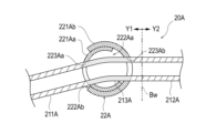
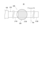
- FIG. 4 is a schematic cross-sectional view showing a state in which the movable portion of the medical device according to the first embodiment is movable;
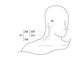
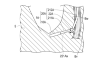
- FIG. 2 is a conceptual diagram showing a state in which the medical device according to the first embodiment is placed inside the living body; 4B is a partially enlarged sectional view of FIG. 4A;
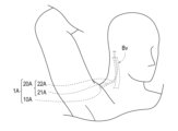
- FIG. 4 is a conceptual diagram showing a state in which the indwelling posture of the medical device according to the first embodiment has changed in vivo.
- FIG. 5C is a partially enlarged cross-sectional view of FIG. 5B; It is a figure which shows the structure of the medical device which concerns on a 2nd form. It is a schematic sectional drawing which shows the medical device which concerns on a 2nd form.
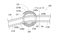
- FIG. 11 is a schematic cross-sectional view showing a state in which the movable portion of the medical device according to the second embodiment is movable; It is a figure which shows the structure of the medical device which concerns on a 3rd form.
- FIG. 11 is a schematic cross-sectional view showing a medical device according to a third embodiment; FIG.
- FIG. 11 is a schematic cross-sectional view showing a state in which the movable portion of the medical device according to the third embodiment is movable; It is a figure which shows the structure of the medical device which concerns on a 4th form. It is a schematic sectional drawing which shows the medical device which concerns on a 4th form.
- FIG. 11 is a schematic cross-sectional view showing a state in which the movable portion of the medical device according to the fourth embodiment is movable;
- the side that is inserted into a biological lumen is defined as the “distal end”, and the side opposite to the distal end side (the side that is grasped or operated by the operator) is defined as the “base end”.
- distal end means a certain range in the axial direction (longitudinal direction) from the distal end
- base end means a certain range in the axial direction from the most proximal end.
- the vascular wall (a two-dot chain line) is schematically shown, and the Y1 side of the vascular wall is the outside of the blood vessel, and the Y2 side is the inside of the blood vessel.
- the medical device 1 As shown in FIG. to the intended delivery site.
- the medical device 1 is left in the living body, penetrates the blood vessel Bv with the medical device 20, and transvascularly delivers the administered substance X to the delivery site.
- the object X to be administered contained in the administration device 10 is a fluid composition that exerts a predetermined effect on the delivery site and can be released from the device.
- the administered object X is, for example, a drug (liquid drug) intended to treat a predetermined disease.
- Drugs include drugs.
- a drug can be any physiologically or pharmacologically active substance, especially one known to be delivered to the human or animal body. Drugs are used in peripheral nerves, adrenergic receptors, cholinergic receptors, skeletal muscle, cardiovascular system, smooth muscle, vascular system, synoptic sites, neuroexchange mobile sites, endocrine and hormonal system, immune system, reproductive organs system, skeletal system, local hormonal system, digestive and excretory system, histamine system, or central nervous system.
- Drugs also include, but are not limited to, drugs used to treat infectious diseases, chronic pain, diabetes, autoimmune diseases, endocrine diseases, metabolic disorders, and rheumatic diseases. Additionally, drugs include peptides, proteins, polypeptides (e.g. enzymes, hormones, cytokines), nucleic acids, oligonucleotides, viruses, viral vectors, plasmids, nucleoproteins, polysaccharides, glycoproteins, lipoproteins, cells, steroids, analgesics , local anesthetics, antibiotic agents, anti-inflammatory corticosteroids, eye drops, other small molecules for pharmaceutical use, or synthetic analogs of these types, and mixtures thereof, and the like. . Specifically, spinraza, baclofen, hyuntalase, brineura, and the like can be used as the administered substance X.
- drugs include peptides, proteins, polypeptides (e.g. enzymes, hormones, cytokines), nucleic acids, oli
- the administration device 10 includes at least a storage section 11 that stores a subject X to be administered, and a release mechanism 12 that releases the subject X stored in the storage section 11 .
- the administration device 10 accommodates the object X to be administered, and is left in a living body (subcutaneous tissue S as an example) while being connected to the medical device 20 .
- the containing portion 11 is a space formed inside the administration device 10 to contain the substance X to be administered.
- the container 11 communicates with the outside (specifically, the medical device 20 ) via an administration opening formed in the housing of the administration device 10 .
- the object X to be administered is released from the opening by driving the release mechanism 12 .
- the release mechanism 12 is configured to be able to control the administration operation of the substance X to be administered based on the administration period of the substance X and predetermined administration conditions (administration timing, administration time, dose, etc.). As long as the release mechanism 12 has a control function related to the administration of the object X to be administered as described above, the configuration of the device for releasing the object to be administered X, the power source required for driving, etc. are not particularly limited.
- the release mechanism 12 can be configured to include, for example, an extrusion section that pushes out the administration subject X accommodated in the accommodation section 11, and a driving section that drives the extrusion section under predetermined conditions.
- the release mechanism 12 can use, as a power source for the drive section, a source capable of generating the power required to drive the drive section, such as moisture in the body, a small battery, or electromagnetic waves.
- the administration device 10 may be a continuous administration device that is left in the body and is capable of sustainably releasing the object X over a long period of time.
- the continuous administration device includes a body portion having a lumen, a liquid permeable portion disposed on the proximal end side of the body portion, and a liquid (moisture in body fluid) disposed upstream of the liquid permeable portion and permeating the liquid permeable portion. ) that expands and pushes the stopper downstream (osmotic engine), the stopper that can slide liquid-tightly in the lumen of the main body, and the administered substance pushed out by the sliding of the stopper.
- the driving portion of the release mechanism 12 is composed of the liquid permeable portion and the pressing portion, the pushing portion is composed of the plug, and the power source of the driving portion is the liquid in the body fluid. becomes water.
- the medical device 20 follows the movement of a tube 21 connected to the administration device 10 and the body tissue while part of the tube 21 is held so as to maintain the posture of the tube 21 puncturing the blood vessel Bv.
- a movable part 22 is provided.
- the tube 21 is a long tubular member connected to the distal end of the administration device 10 and extending from the administration device 10 through the blood vessel Bv to the delivery site.
- the tube 21 has a lumen communicating from the proximal end of the first portion 211 to the distal end of the second portion 212 .
- the tube 21 has a first portion 211 located on the administration device 10 side with the blood vessel wall Bw as a boundary, and a second portion 212 located on the delivery site side with the blood vessel wall Bw as a boundary.
- a first portion 211 of the tube 21 is left in the living body outside the blood vessel Bv, and a second portion 212 is inserted through the blood vessel wall Bw into the blood vessel Bv.
- the tip of the second portion 212 is inserted through the blood vessel Bv to the delivery site, and delivers the administered substance X released from the administration device 10 to the delivery site.
- the portion of the first portion 211 of the tube 21 to which the movable portion 22 is attached becomes the third portion 213 . That is, the third portion 213 constitutes part of the first portion 211 of the two portions that separate the tube 21 with the blood vessel wall Bw as a boundary.
- connection between the tube 21 and the administration device 10 is a form in which a thread (or thread groove) formed at the distal end of the administration device 10 and a thread groove (or thread) formed at the proximal end of the tube 21 are screwed together.
- a thread or thread groove
- a thread groove or thread formed at the proximal end of the tube 21
- the movable portion 22 is attached to the first portion 211 of the tube 21, and maintains communication with the first portion 211 and the second portion 212, and at least the second portion 212 is maintained in a posture of puncturing the blood vessel Bv. , while holding a part of the first portion 211, it moves following the movement of the living tissue. More preferably, the movable part 22 is mounted on the first part 211 in a state of covering and holding the third part 213 corresponding to the mounting part of the movable part 22 in the first part 211 , and is located on the tip side of the third part 213 .
- the third part 213 and the first part closer to the proximal end than the third part 213 are moved by the movement of the living tissue.
- 211 can be moved by following the posture change.
- the movable part 22 maintains communication between the first portion 211 and the second portion 212 of the tube 21, and allows the administration device 10 and the tube 21 to assume a posture (for example, an indwelling posture of the administration device 10) according to the movement of surrounding living tissue. , the posture of puncturing the blood vessel Bv of the tube 21 and the posture of indwelling in the living body), it moves following the movement of the living tissue. Since the movable portion 22 moves following the movement of the living tissue, the first portion 211 and the second portion 212 on the distal side (delivery site side) of the third portion 213 are affected by the movement of the living tissue. it gets harder. Therefore, the medical device 20 can reduce the burden on the blood vessel Bv due to displacement of the tube 21 .
- a posture for example, an indwelling posture of the administration device 10.
- the movable part 22 can be mounted so as to cover the third part 213 and its surroundings so as to prevent the lumen of the third part 213 from collapsing due to the movement of the surrounding living tissue. As a result, the third portion 213 of the tube 21 is crushed by the surrounding living tissue, and the communication state of the tube 21 is maintained.
- the tube 21 is not particularly limited as long as it is a material that can be applied in the medical field and has sufficient rigidity to suppress buckling against the movement of the surrounding living tissue.
- the constituent material of the tube 21 is, for example, polyolefin (eg, polyethylene, polypropylene, polybutene, ethylene-propylene copolymer, ethylene-vinyl acetate copolymer, ionomer, or these mixture of two or more), polyolefin elastomer, crosslinked polyolefin, polyvinyl chloride, polyamide, polyamide elastomer, polyester, polyester elastomer, polyurethane, polyurethane elastomer, fluorine resin, polycarbonate, polystyrene, polyacetal, polyimide, polyetherimide , polymer materials such as aromatic polyetherketone, resin materials such as mixtures thereof, shape memory alloys, metal materials such as stainless steel, tantalum, titanium,
- polyolefin e
- the third portion 213 of the tube 21 can be made of the same material as the first portion 211, but can more flexibly follow the movement of the movable portion 22 accompanying the change in posture of the administration device 10 and the tube 21. Therefore, a material other than the third portion 213, which is more flexible than the first portion 211 and the second portion 212, can be applied. Even if the third portion 213 of the medical device 20 is made of a material that is more flexible than the first portion 211 and the second portion 212, by attaching the movable portion 22 while covering the third portion 213, Collapse of the lumen due to surrounding living tissue can be prevented.
- the medical device 1A to medical device 1D can be configured as shown in the following first to fourth modes. It should be noted that each form described below is merely an example and does not limit the components and actions of the medical device 1 . In addition, in the first to fourth embodiments described below, detailed descriptions of components having the same functions as those of the above-described embodiments are omitted, and configurations, members, and methods of use that are not particularly mentioned are It may be similar to the embodiment described above.
- the medical devices 1A to 1D differ in the configuration and action of the movable portions 22A to 22D, respectively, and other configurations (administration devices 10A to 10D, tubes 21 of the medical devices 20A to 20D, etc.) , can be configured in the same manner as the administration device 10 and the tube 21 described above. Therefore, in the following description, the configurations and actions of the movable parts 22A to 22D, which are characteristic requirements of each form, will be mainly referred to.
- the medical device 1A comprises an administration device 10A and a medical instrument 20A, as shown in FIGS. 2-3B.
- the movable portion 22A of the medical device 20A is mounted on the proximal side of the third portion 213A of the tube 21A, and serves as the center of rotation when the posture of the first portion 211A on the proximal side of the third portion 213A changes. and a second movable portion 221Ab attached to the distal end side of the third portion 213A and rotatably holding the first movable portion 221Aa while covering a part of the first movable portion 221Aa.
- the first movable portion 221Aa is rotatably fitted into the second movable portion 221Ab.
- the movable part 22A has a configuration in which the first movable part 221Aa is rotatably held.
- the first movable portion 221Aa rotates while holding part of the third portion 213A so as to follow changes in posture of the administration device 10A and the tube 21A, and can absorb these changes in posture. Therefore, the medical device 20A can maintain the posture of the tube 21A (more specifically, the placement posture of the first portion 211A on the distal side of the third portion 213A and the puncture posture of the second portion 212A with respect to the blood vessel Bv). .
- the first movable part 221Aa is a substantially hollow sphere with an internal space.
- the first movable portion 221Aa is partially formed with an opening 222Aa that communicates with the internal space, and is formed with an insertion hole 223Aa at a position facing the opening 222Aa through which the third portion 213A of the tube 21A is inserted.
- the first movable portion 221Aa is fitted into the internal space of the second movable portion 221Ab with the opening 222Aa facing the opening 222Ab of the second movable portion 221Ab.
- the second movable part 221Ab is a substantially hollow sphere having an internal space into which the first movable part 221Aa can be fitted.
- the second movable portion 221Ab is partially formed with an opening 222Ab that communicates with the internal space, and is formed with an insertion hole 223Ab at a position facing the opening 222Ab, through which the third portion 213A of the tube 21A is inserted.
- the second movable portion 221Ab rotatably holds the first movable portion 221Aa that is inserted into the internal space with the opening 222Aa facing the opening 222Ab.
- the opening 222Ab of the second movable part 221Ab preferably has an opening size (opening diameter) that does not come off when the first movable part 221Aa rotates. Also, when the first movable portion 221Aa is rotated in a state where the first movable portion 221Aa is fitted in the second movable portion 221Ab, the surrounding living tissue enters between the first movable portion 221Aa and the second movable portion 221Ab.
- the outer size (outer diameter) of the first movable portion 221Aa and the inner space size (inner diameter) of the second movable portion 221Ab are defined so as to prevent this.
- the outer peripheral surface of the first movable portion 221Aa and the inner peripheral surface of the second movable portion 221Ab may be defined to be in contact with each other. It may be defined so that there is a gap.
- the tip of the third portion 213A of the tube 21A is fixed to the inner peripheral surface of the insertion hole 223Ab while protruding from the opening 222Aa by a predetermined length from the tip side to the base end side.
- the base end side of the third portion 213A is fixed to the inner peripheral surface of the insertion hole 223Aa. That is, the third portion 213A is held by the second movable portion 221Ab at the distal end and held by the first movable portion 221Aa at the proximal end, but the other portions are in a free state in which they are not fixed.
- the third portion 213A can be flexibly deformed, so that the lumen shape of the third portion 213A is maintained. and buckling of the tube 21A is prevented.
- the medical device 1A is placed in the subcutaneous tissue S near the neck as an indwelling position in the living body, and the blood vessel Bv through which the tube 21A is punctured is the jugular vein.
- the indwelling position of the medical device 1A is not limited to the vicinity of the neck shown in FIGS. 4A and 4B, since the blood vessel Bv through which the tube 21A is punctured is determined by the position of the delivery site of the object X to be administered.
- the indwelling position of the medical device 1A and the blood vessel Bv to be punctured can be appropriately determined according to the position of the delivery site of the object X to be administered.
- the medical device 1A is indwelled in the subcutaneous tissue S in the vicinity of the neck where the jugular vein to be punctured runs based on the position of the delivery site of the object X to be administered.
- the medical device 1A is to be indwelled, first, the skin near the indwelling position is incised to expose the jugular vein (blood vessel Bv), and the tube 21A is introduced by puncturing the blood vessel Bv.
- the tube 21A can be introduced by puncturing the blood vessel Bv by a well-known introduction method.
- the administration device 10A is left in the subcutaneous tissue S (or fixed to the jugular vein with suture or adhesive) while being connected to the tube 21A.
- the indwelling posture of the administration apparatus 10A has changed from the beginning of indwelling due to the movement of the surrounding living tissue.
- the medical device 1A includes the medical instrument 20A, it can move about the first movable portion 221Aa of the movable portion 22A as the center of rotation, and can absorb changes in posture of the administration device 10A. Therefore, even if the posture of the administration device 10A or the like changes due to the movement of the living tissue, the medical device 1A can maintain the placement posture of the first portion 211A on the distal side of the third portion 213A of the tube 21A and the blood vessel of the second portion 212A. The puncture posture with respect to Bv can be maintained.
- the medical device 20A is attached to the proximal side of the third portion 213A of the tube 21A, and is the first movable body that serves as the center of rotation as the posture of the first portion 211A, which is closer to the proximal side than the third portion 213A, changes.
- a movable portion composed of a portion 221Aa and a second movable portion 221Ab attached to the distal end side of the third portion 213A and rotatably holding the first movable portion 221Aa while covering a part of the first movable portion 221Aa. 22A. As shown in FIG. 3B and FIG.
- the movable part 22A can maintain the movement of the body tissue around the medical device 1A even if the placement posture of the components of the medical device 1A (for example, the administration device 10A) changes from the initial placement. It is possible to move the first movable portion 221Aa as the center of rotation to absorb changes in posture of the administration device 10A. Therefore, the indwelling posture of the first portion 211A on the distal side of the third portion 213A of the tube 21A and the puncturing posture of the second portion 212A with respect to the blood vessel Bv are maintained in the initial state of indwelling. Therefore, the medical device 1A including the medical instrument 20A suppresses the load applied to the puncture site of the blood vessel Bv even if the surrounding living tissue moves after being placed in the living body. Risk can be reduced.
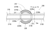
- the medical device 1B of the second embodiment differs from the medical device 1A of the first embodiment in that the medical device 20B includes a cover portion 230 that covers the second movable portion 221Bb holding the first movable portion 221Ba. . Therefore, the administration device 10B, the tube 21B, and the movable portion 22B (the first movable portion 221Ba and the second movable portion 221Bb) of the medical device 20B, which constitute the medical device 1B, are configured with the corresponding portions of the medical device 1A of the first embodiment. and functions match.
- the medical device 1B according to the second embodiment has the same configuration as the medical device 1A according to the first embodiment, but is given a different reference numeral.
- the medical device 1B includes an administration device 10B and a medical instrument 20B, as shown in any of FIGS. 6, 7A, and 7B.
- the movable portion 22B of the medical device 20B is mounted on the proximal side of the third portion 213B of the tube 21B, and serves as the center of rotation when the posture of the first portion 211B on the proximal side of the third portion 213B changes.
- a cover portion 230 is provided to cover the held second movable portion 221Bb.
- the cover part 230 forms a substantially hollow sphere.
- the cover portion 230 is partially formed with an opening portion 231 that allows the attitude change of the first portion 211B closer to the base end than the third portion 213B of the tube 21B connected to the first movable portion 221Ba.
- the opening portion 231 is defined to have an opening size (opening diameter) that does not hinder the posture change of the first portion 211B closer to the proximal end than the third portion 213B of the tube 21B due to the rotation of the first movable portion 221Ba.
- the cover portion 230 is formed with an insertion hole 232 through which the third portion 213B of the tube 21B that is inserted through the second movable portion 221Bb is inserted.
- the inner peripheral surface of the insertion hole 232 may be in contact with the outer peripheral surface of the third portion 213B, or may have some gap between it and the third portion 213B.
- the cover part 230 is a member for preventing the surrounding living tissue from being pulled into the gap between the first movable part 221Ba and the second movable part 221Bb when the first movable part 221Ba rotates. Therefore, the cover portion 230 is configured to cover at least the overlapping region between the first movable portion 221Ba and the second movable portion 221Bb in the fitted state of the first movable portion 221Ba and the second movable portion 221Bb.
- the constituent material of the cover part 230 is not particularly limited as long as it is a material having biocompatibility, such as a material similar to that of the tube 21B.
- the medical device 20B is configured by the first movable portion 221Ba, the second movable portion 221Bb, and the cover portion 230 that covers the second movable portion 221Bb while holding the first movable portion 221Ba.
- a portion 22B is provided.
- the movable part 22B is set to the first movable position even if the placement posture of the components of the medical device 1B (for example, the administration device 10B) changes from the initial placement due to the movement of the living tissue around the medical device 1B. It is possible to absorb changes in posture of the administration device 10B by moving around the portion 221Ba as the center of rotation.
- the indwelling posture of the first portion 211B on the distal side of the third portion 213B of the tube 21B and the puncturing posture of the second portion 212B with respect to the blood vessel Bv are maintained in the initial state of indwelling. Therefore, the medical device 1B including the medical instrument 20B suppresses the load applied to the puncture site of the blood vessel Bv even if the surrounding living tissue moves after being indwelled in the living body. Risk can be reduced.
- the medical device 20B since the medical device 20B includes the cover portion 230, in addition to the above-described effect of reducing the risk of bleeding, the rotational movement of the first movable portion 221Ba causes the living body to move between the first movable portion 221Ba and the second movable portion 221Bb. It is also possible to achieve the effect of preventing the rotation of the first movable portion 221Ba from being hindered due to the tissue being pulled in.
- the medical device 1C of the third embodiment differs in structure from the movable portion 22A of the medical device 1A of the first embodiment and the movable portion 22B of the medical device 1B of the second embodiment. It has the structure which supports the 3rd part 213C, deform
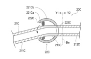
- the medical device 1C includes an administration device 10C and a medical instrument 20C, as shown in FIGS. 8, 9A, and 9B.
- the movable portion 22C of the medical device 20C includes a support portion 221Ca that supports the third portion 213C while deforming following changes in posture of the first portion 211C on the proximal side of the third portion 213C of the tube 21C, and a third portion 213C. and a protective portion 221Cb that has an opening 222C that allows the position of the first portion 211C on the proximal side of the portion 213C to change, and that covers the third portion 213C supported by the support portion 221Ca.
- the support portion 221Ca is attached to the protection portion 221Cb (in FIG. 9A, the inner peripheral surface of the protection portion 221Cb), and deforms in accordance with the change in posture of the third portion 213C due to the movement of the living tissue to support at least the third portion 213C.
- one end of the supporting portion 221Ca is connected to the boundary between the first portion 211C and the third portion 213C.
- the connection position with is not particularly limited.
- the support part 221Ca is preferably composed of a member having a characteristic of following changes in posture of the third portion 213C and supporting the third portion 213C so that it does not buckle due to excessive posture change.
- the support portion 221Ca can be configured by a spring member such as a coiled spring or an elastic member such as an elastic body made of synthetic rubber.
- the protective part 221Cb has a substantially hollow hemispherical shape with an opening 222C in part. Further, the protective portion 221Cb is formed with an insertion hole 223C through which the third portion 213C is inserted. The protection portion 221Cb is attached to the tip side of the third portion 213C while covering the third portion 213C.
- the protective portion 221Cb is configured to cover the third portion 213C and a portion of the distal end side of the first portion 211C that is continuous with the third portion 213C, and is configured to cover at least the third portion 213C. All you have to do is Also, the opening size (opening diameter) of the opening 222C of the protection portion 221Cb is not particularly limited, and may be any size that does not hinder the posture change of the first portion 211C.
- the third portion 213C is fixed to the protective portion 221Cb with the distal end inserted through the insertion hole 223C, the base end side is supported in a suspended state by the support portion 221Ca, and the other portions are in a free state where they are not fixed. Become. Therefore, the third portion 213C, for example, when the posture of the first portion 211C changes, the support portion 221Da is deformed (extended or contracted) in a predetermined direction, so that the first portion 211C closer to the proximal end than the third portion 213C is. (see FIG. 9B).
- the medical device 20C includes the support portion 221Ca that supports the third portion 213C while deforming in accordance with the posture change of the first portion 211C closer to the proximal end than the third portion 213C of the tube 21C, and the third portion 213C.
- the movable portion 22C includes a protection portion 221Cb that has an opening 222C that allows the position of the first portion 211C on the proximal side of the portion 213C to change, and that covers the third portion 213C supported by the support portion 221Ca. Prepare. As shown in FIG.
- the movable part 22C is configured to support the support part 221Ca even if the placement posture of the components of the medical device 1C (for example, the administration device 10C) changes from the initial placement due to the movement of the living tissue around the medical device 1C. can appropriately deform to follow the posture change of the first portion 211C closer to the proximal side than the third portion 213C. Therefore, the indwelling posture of the first portion 211C on the distal side of the third portion 213C of the tube 21C and the puncturing posture of the second portion 212C with respect to the blood vessel Bv are maintained in the initial state of indwelling. Therefore, the medical device 1C including the medical instrument 20C suppresses the load applied to the puncture site of the blood vessel Bv even if the surrounding living tissue moves after being placed in the living body. Risk can be reduced.
- the medical device 1D of the fourth form is a modification of the medical device 1C of the third form, and has a configuration in which the shape and function of the support portion 221Ca of the third form are partially changed.
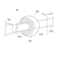
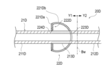
- the medical device 1D as shown in FIGS. 10, 11A, and 11B, includes an administration device 10D and a medical instrument 20D.
- the movable portion 22D of the medical device 20D includes a support portion 221Da that supports the third portion 213D while deforming in accordance with the posture change of the first portion 211D closer to the proximal end than the third portion 213D of the tube 21D; and a protective portion 221Db that has an opening 222D that allows the position of the first portion 211D on the proximal side of the portion 213D to change, and that covers the third portion 213D supported by the support portion 221Da.
- the support part 221Da is attached to the protection part 221Db, and supports at least the third part 213D while deforming according to the posture change of the third part 213D caused by the movement of the living tissue.
- the support portion 221Da is attached to an opening 222D formed in the protection portion 221Db, and an insertion hole 224D through which the third portion 213D is inserted is formed in a substantially central portion.
- the support portion 221Da has a shape in which a flexible, substantially circular plate material is bellows-folded along the radial direction of the tube 21D from the outer peripheral surface of the third portion 213D (concentrically alternating peaks and valleys).
- the support portion 221Da can be made of an elastic material (for example, synthetic rubber or synthetic resin) that has flexibility and can expand and contract following changes in the posture of the third portion 213D. Note that the support portion 221Da does not necessarily need to be made of an elastic material because it has a structure that can be expanded and contracted by the accordion folding. Further, as shown in FIG. 11A, the support portion 221Da is connected to the boundary portion between the first portion 211D and the third portion 213D. The connection position with is not particularly limited.
- the protective part 221Db has a substantially hollow hemispherical shape with an opening 222D in part. Further, the protective portion 221Db is formed with an insertion hole 223D through which the third portion 213D is inserted. The protective portion 221Db is attached to the tip side of the third portion 213D while covering the third portion 213D.
- the opening size (opening diameter) of the opening 222D of the protection portion 221Db is not particularly limited, and may be any size that does not hinder the posture change of the first portion 211D.
- the third portion 213D is fixed to the support portion 221Da with its distal end inserted through the insertion hole 223D and its base end inserted through the insertion hole 224D, and other portions are left unfixed. Therefore, the third portion 213D is deformed (extended or contracted) in a predetermined direction by the support portion 221Da when the posture of the first portion 211D is changed, for example, so that the first portion 211D on the base end side of the third portion 213D is moved. (See FIG. 11B).
- the medical device 20D supports the third portion 213D of the tube 21D while deforming in accordance with the posture change of the first portion 211D closer to the proximal end than the third portion 213D of the tube 21D, as in the third embodiment.
- a portion 221Da, and a protection portion 221Db that has an opening 222D that allows a change in posture of the first portion 211D on the proximal side of the third portion 213D and that covers the third portion 213D supported by the support portion 221Da.
- a movable part 22D is provided. As shown in FIG.
- the movable part 22D is configured to support the supporting part 221Da even if the placement posture of the components of the medical device 1D (for example, the administration device 10D) changes from the initial placement due to the movement of the living tissue around the medical device 1D. can appropriately deform to follow the posture change of the first portion 211D closer to the proximal side than the third portion 213D. Therefore, the indwelling posture of the first portion 211D on the distal side of the third portion 213D of the tube 21D and the puncturing posture of the second portion 212D with respect to the blood vessel Bv are maintained in the initial state of indwelling. Therefore, the medical device 1D including the medical instrument 20D suppresses the load applied to the puncture site of the blood vessel Bv even if the surrounding living tissue moves after being indwelled in the body. Risk can be reduced.
- the medical device 20 is attached to the administration device 10 that is indwelled at a position in the living body where movement occurs in the surrounding living tissue, and the administration device 10 ejects the object X to be administered.
- a tube 21 having a first portion 211 and a second portion 212 located closer to the delivery site side than the blood vessel wall Bw, and attached to the first portion 211 to hold a portion of the first portion 211 while the body tissue is being cut. and a movable part 22 that moves following the movement.
- the movable part 22 can move while holding at least a part of the first portion 211 of the tube 21 while following changes in posture of the administration device 10 and the tube 21 due to movement of living tissue. Therefore, the posture of the second portion 212 of the tube 21 to puncture the blood vessel Bv can be maintained. Therefore, even if the postures of the administration device 10 and the tube 21 change due to the movement of the living tissue at the indwelling destination, the medical device 20 absorbs these posture changes and suppresses the load applied to the puncture site of the blood vessel Bv. can reduce the risk of bleeding due to unsealing.
- the movable part 22 is mounted on the first part 211 while covering and holding the third part 213 corresponding to the mounting part of the movable part 22 in the first part 211, It is also possible to adopt a configuration in which the third portion 213 and the first portion 211 closer to the proximal end than the third portion 213 are moved following the change in posture caused by the movement of living tissue.
- the third portion 213 of the tube 21 to which the movable portion 22 is attached is covered with the movable portion 22, so that the third portion 213 is prevented from being crushed by the surrounding living tissue.
- the communication state of the tube 21 is maintained.
- the movable portion 22A is mounted on the proximal side of the third portion 213A so as to cover a part of the third portion 213A, and is located on the proximal side of the third portion 213A.
- the first movable part 221Aa which serves as the center of rotation when the posture of the first part 211A changes, is attached to the distal end side of the third part 213A, and the first movable part 221Aa can be rotated while covering a part of the first movable part 221Aa. It is good also as a structure provided with 2nd movable part 221Ab hold
- the medical device 20A can rotate around the first movable portion 221Aa even if the placement posture of the administration device 10A changes from the initial placement due to the movement of the living tissue around the medical device 1A. posture change can be absorbed. As a result, the indwelling posture of the first portion 211A on the distal side of the third portion 213A of the tube 21A and the puncturing posture of the second portion 212A with respect to the blood vessel Bv are maintained in the initial state of indwelling. Therefore, the medical device 20A can suppress the load applied to the puncture site of the blood vessel Bv, and reduce the risk of bleeding due to releasing the seal of the puncture site.
- the movable portion 22B has an opening 231 that allows the first portion 211B on the proximal side of the third portion 213B to change its posture, and the first movable portion 221Ba.
- a configuration may be adopted in which a cover portion 230 that covers the held second movable portion 221Bb is further provided.
- the medical device 20B includes the cover portion 230. Therefore, in addition to the effect of reducing the risk of bleeding caused by changes in the indwelling posture of the components of the medical device 1B (for example, the administration device 10B), the first It is also possible to prevent the rotation of the first movable portion 221Ba from being hindered due to the living tissue being drawn between the first movable portion 221Ba and the second movable portion 221Bb due to the rotational movement of the movable portion 221Ba.
- the movable portions 22C and 22D are deformed while following the posture change of the first portions 211C and 211D closer to the proximal side than the third portions 213C and 213D. It has support portions 221Ca and 221Da that support the three portions 213C and 213D, and opening portions 222C and 222D that allow posture changes of the first portions 211C and 211D closer to the proximal side than the third portions 213C and 213D.
- a configuration including protection portions 221Cb and 221Db covering the third portions 213C and 213D supported by 221Ca and 221Da may be provided.
- the components of the medical devices 1C and 1D change their placement postures from the beginning of placement due to the movement of the living tissue around the medical devices 1C and 1D. Even so, the support portions 221Ca and 221Da can follow the tubes 21C and 21D while deforming appropriately to absorb the posture change of the administration devices 10C and 10D.
- the medical instruments 20C and 20D can suppress the load applied to the puncture site of the blood vessel Bv, and reduce the risk of bleeding due to releasing the seal at the puncture site.
- the medical device 1 is equipped with any of the medical instruments 20 (20A to 20D) described above and the medical instrument 20 (20A to 20D) on the distal end side, and is equipped with the surrounding biological tissue in vivo. and an administration device 10 (10A to 10D) indwelled at a position where movement occurs, and the administration subject X released from the administration device 10 (10A to 10D) is passed through the medical device 20 (20A to 20D). delivered to the delivery site.
- the administration device 10 and the tube 21 may change from the initial placement posture due to the movement of the surrounding living tissue.
- a load is applied to the blood vessel wall Bw of the blood vessel Bv, which is the puncture site, and there is a risk that the seal will be released and bleeding will occur.
- the movable part 22 can move while holding at least a part of the first portion 211 of the tube 21 while following changes in posture of the administration device 10 and the tube 21 due to movement of living tissue.
- the puncturing posture of the second portion 212 with respect to the blood vessel Bv can be maintained.
- the medical device 1 including the medical device 20 absorbs the change in posture and reduces the load applied to the puncture site of the blood vessel Bv. and reduce the risk of bleeding due to unsealing of the puncture site.
Landscapes
- Health & Medical Sciences (AREA)
- Engineering & Computer Science (AREA)
- Animal Behavior & Ethology (AREA)
- Anesthesiology (AREA)
- Biomedical Technology (AREA)
- Heart & Thoracic Surgery (AREA)
- Hematology (AREA)
- Life Sciences & Earth Sciences (AREA)
- General Health & Medical Sciences (AREA)
- Public Health (AREA)
- Veterinary Medicine (AREA)
- Medical Informatics (AREA)
- Dermatology (AREA)
- Vascular Medicine (AREA)
- Infusion, Injection, And Reservoir Apparatuses (AREA)
Priority Applications (1)
| Application Number | Priority Date | Filing Date | Title |
|---|---|---|---|
| JP2023564816A JPWO2023100571A1 (cg-RX-API-DMAC7.html) | 2021-11-30 | 2022-10-31 |
Applications Claiming Priority (2)
| Application Number | Priority Date | Filing Date | Title |
|---|---|---|---|
| JP2021193955 | 2021-11-30 | ||
| JP2021-193955 | 2021-11-30 |
Publications (1)
| Publication Number | Publication Date |
|---|---|
| WO2023100571A1 true WO2023100571A1 (ja) | 2023-06-08 |
Family
ID=86611932
Family Applications (1)
| Application Number | Title | Priority Date | Filing Date |
|---|---|---|---|
| PCT/JP2022/040618 Ceased WO2023100571A1 (ja) | 2021-11-30 | 2022-10-31 | 医療器具および医療デバイス |
Country Status (2)
| Country | Link |
|---|---|
| JP (1) | JPWO2023100571A1 (cg-RX-API-DMAC7.html) |
| WO (1) | WO2023100571A1 (cg-RX-API-DMAC7.html) |
Citations (3)
| Publication number | Priority date | Publication date | Assignee | Title |
|---|---|---|---|---|
| JP2008508024A (ja) * | 2004-07-28 | 2008-03-21 | アーディアン インコーポレイテッド | 腎神経ブロッキング方法及び装置 |
| JP2011505988A (ja) * | 2007-12-11 | 2011-03-03 | マサチューセッツ インスチテュート オブ テクノロジー | 膀胱および他の身体の小嚢又は管腔を治療するための埋め込み型薬物供給デバイスおよび方法 |
| JP2020023562A (ja) * | 2009-09-28 | 2020-02-13 | インターシア セラピューティクス,インコーポレイティド | 実質的な定常状態薬物送達の迅速な確立及び/又は停止 |
-
2022
- 2022-10-31 JP JP2023564816A patent/JPWO2023100571A1/ja active Pending
- 2022-10-31 WO PCT/JP2022/040618 patent/WO2023100571A1/ja not_active Ceased
Patent Citations (3)
| Publication number | Priority date | Publication date | Assignee | Title |
|---|---|---|---|---|
| JP2008508024A (ja) * | 2004-07-28 | 2008-03-21 | アーディアン インコーポレイテッド | 腎神経ブロッキング方法及び装置 |
| JP2011505988A (ja) * | 2007-12-11 | 2011-03-03 | マサチューセッツ インスチテュート オブ テクノロジー | 膀胱および他の身体の小嚢又は管腔を治療するための埋め込み型薬物供給デバイスおよび方法 |
| JP2020023562A (ja) * | 2009-09-28 | 2020-02-13 | インターシア セラピューティクス,インコーポレイティド | 実質的な定常状態薬物送達の迅速な確立及び/又は停止 |
Also Published As
| Publication number | Publication date |
|---|---|
| JPWO2023100571A1 (cg-RX-API-DMAC7.html) | 2023-06-08 |
Similar Documents
| Publication | Publication Date | Title |
|---|---|---|
| EP2968762B1 (en) | Multi-chamber injection device | |
| US9005163B2 (en) | Balloon catheter with external delivery tube | |
| CN103180007B (zh) | 留置内腔装置 | |
| US20120109065A1 (en) | Transdermal Fluid Delivery Device | |
| US10518071B2 (en) | Transdermal microneedle drug delivery device and method | |
| US20070016149A1 (en) | Injection Needle | |
| JPS6077766A (ja) | 腹腔内インスリン投薬装置 | |
| JP2001510080A (ja) | 皮下ポートに経皮接近するためのカテーテルアセンブリ | |
| US20260007820A1 (en) | Torsional insertion devices | |
| JPH0663145A (ja) | 血管内投薬用バルーンカテーテル | |
| US7731705B2 (en) | Eluting coils and methods of deploying and retrieving | |
| AU2019388777B2 (en) | Implantable reservoir for use with a medical device and system for interventional drug delivery | |
| KR102244030B1 (ko) | 무바늘 무통주사기용 약액주입 보조 키트 | |
| US7758549B2 (en) | Injection needle assembly comprising an injection needle and a needle guide | |
| US20140005595A1 (en) | Delivery devices and methods for delivering therapeutic agents | |
| CN117731920A (zh) | 一种微针球囊介入装置及系统 | |
| EP4431142A1 (en) | Administration device | |
| KR102047610B1 (ko) | 다수의 소형 주사기 또는 주사부를 갖는 마이크로 니들 장치 | |
| AU2021397261A9 (en) | Squeezable subcutaneous port | |
| JP6765990B2 (ja) | 医療用デバイス | |
| WO2023080251A1 (ja) | 医療器具 | |
| US12539234B2 (en) | Ocular drug delivery devices | |
| US20130331777A1 (en) | Delivery devices and methods for delivering therapeutic agents | |
| EP4295873A1 (en) | An infusion catheter system | |
| WO2023181997A1 (ja) | 持続投与装置 |
Legal Events
| Date | Code | Title | Description |
|---|---|---|---|
| 121 | Ep: the epo has been informed by wipo that ep was designated in this application |
Ref document number: 22901004 Country of ref document: EP Kind code of ref document: A1 |
|
| ENP | Entry into the national phase |
Ref document number: 2023564816 Country of ref document: JP Kind code of ref document: A |
|
| NENP | Non-entry into the national phase |
Ref country code: DE |
|
| 122 | Ep: pct application non-entry in european phase |
Ref document number: 22901004 Country of ref document: EP Kind code of ref document: A1 |