WO2023100552A1 - 航空機用化粧室ユニットの扉開閉機構 - Google Patents
航空機用化粧室ユニットの扉開閉機構 Download PDFInfo
- Publication number
- WO2023100552A1 WO2023100552A1 PCT/JP2022/040083 JP2022040083W WO2023100552A1 WO 2023100552 A1 WO2023100552 A1 WO 2023100552A1 JP 2022040083 W JP2022040083 W JP 2022040083W WO 2023100552 A1 WO2023100552 A1 WO 2023100552A1
- Authority
- WO
- WIPO (PCT)
- Prior art keywords
- door
- open position
- restroom
- closed position
- sensor
- Prior art date
- Legal status (The legal status is an assumption and is not a legal conclusion. Google has not performed a legal analysis and makes no representation as to the accuracy of the status listed.)
- Ceased
Links
Images








Classifications
-
- B—PERFORMING OPERATIONS; TRANSPORTING
- B64—AIRCRAFT; AVIATION; COSMONAUTICS
- B64D—EQUIPMENT FOR FITTING IN OR TO AIRCRAFT; FLIGHT SUITS; PARACHUTES; ARRANGEMENT OR MOUNTING OF POWER PLANTS OR PROPULSION TRANSMISSIONS IN AIRCRAFT
- B64D11/00—Passenger or crew accommodation; Flight-deck installations not otherwise provided for
- B64D11/02—Toilet fittings
-
- E—FIXED CONSTRUCTIONS
- E05—LOCKS; KEYS; WINDOW OR DOOR FITTINGS; SAFES
- E05D—HINGES OR SUSPENSION DEVICES FOR DOORS, WINDOWS OR WINGS
- E05D15/00—Suspension arrangements for wings
- E05D15/26—Suspension arrangements for wings for folding wings
- E05D15/264—Suspension arrangements for wings for folding wings for bi-fold wings
-
- E—FIXED CONSTRUCTIONS
- E05—LOCKS; KEYS; WINDOW OR DOOR FITTINGS; SAFES
- E05F—DEVICES FOR MOVING WINGS INTO OPEN OR CLOSED POSITION; CHECKS FOR WINGS; WING FITTINGS NOT OTHERWISE PROVIDED FOR, CONCERNED WITH THE FUNCTIONING OF THE WING
- E05F1/00—Closers or openers for wings, not otherwise provided for in this subclass
- E05F1/08—Closers or openers for wings, not otherwise provided for in this subclass spring-actuated, e.g. for horizontally sliding wings
- E05F1/10—Closers or openers for wings, not otherwise provided for in this subclass spring-actuated, e.g. for horizontally sliding wings for swinging wings, e.g. counterbalance
- E05F1/1008—Closers or openers for wings, not otherwise provided for in this subclass spring-actuated, e.g. for horizontally sliding wings for swinging wings, e.g. counterbalance with a coil spring parallel with the pivot axis
- E05F1/1016—Closers or openers for wings, not otherwise provided for in this subclass spring-actuated, e.g. for horizontally sliding wings for swinging wings, e.g. counterbalance with a coil spring parallel with the pivot axis with a canted-coil torsion spring
-
- E—FIXED CONSTRUCTIONS
- E05—LOCKS; KEYS; WINDOW OR DOOR FITTINGS; SAFES
- E05F—DEVICES FOR MOVING WINGS INTO OPEN OR CLOSED POSITION; CHECKS FOR WINGS; WING FITTINGS NOT OTHERWISE PROVIDED FOR, CONCERNED WITH THE FUNCTIONING OF THE WING
- E05F15/00—Power-operated mechanisms for wings
- E05F15/40—Safety devices, e.g. detection of obstructions or end positions
-
- E—FIXED CONSTRUCTIONS
- E05—LOCKS; KEYS; WINDOW OR DOOR FITTINGS; SAFES
- E05F—DEVICES FOR MOVING WINGS INTO OPEN OR CLOSED POSITION; CHECKS FOR WINGS; WING FITTINGS NOT OTHERWISE PROVIDED FOR, CONCERNED WITH THE FUNCTIONING OF THE WING
- E05F15/00—Power-operated mechanisms for wings
- E05F15/60—Power-operated mechanisms for wings using electrical actuators
-
- E—FIXED CONSTRUCTIONS
- E05—LOCKS; KEYS; WINDOW OR DOOR FITTINGS; SAFES
- E05F—DEVICES FOR MOVING WINGS INTO OPEN OR CLOSED POSITION; CHECKS FOR WINGS; WING FITTINGS NOT OTHERWISE PROVIDED FOR, CONCERNED WITH THE FUNCTIONING OF THE WING
- E05F15/00—Power-operated mechanisms for wings
- E05F15/60—Power-operated mechanisms for wings using electrical actuators
- E05F15/603—Power-operated mechanisms for wings using electrical actuators using rotary electromotors
- E05F15/605—Power-operated mechanisms for wings using electrical actuators using rotary electromotors for folding wings
-
- E—FIXED CONSTRUCTIONS
- E05—LOCKS; KEYS; WINDOW OR DOOR FITTINGS; SAFES
- E05F—DEVICES FOR MOVING WINGS INTO OPEN OR CLOSED POSITION; CHECKS FOR WINGS; WING FITTINGS NOT OTHERWISE PROVIDED FOR, CONCERNED WITH THE FUNCTIONING OF THE WING
- E05F15/00—Power-operated mechanisms for wings
- E05F15/70—Power-operated mechanisms for wings with automatic actuation
- E05F15/73—Power-operated mechanisms for wings with automatic actuation responsive to movement or presence of persons or objects
-
- E—FIXED CONSTRUCTIONS
- E05—LOCKS; KEYS; WINDOW OR DOOR FITTINGS; SAFES
- E05F—DEVICES FOR MOVING WINGS INTO OPEN OR CLOSED POSITION; CHECKS FOR WINGS; WING FITTINGS NOT OTHERWISE PROVIDED FOR, CONCERNED WITH THE FUNCTIONING OF THE WING
- E05F15/00—Power-operated mechanisms for wings
- E05F15/70—Power-operated mechanisms for wings with automatic actuation
- E05F15/73—Power-operated mechanisms for wings with automatic actuation responsive to movement or presence of persons or objects
- E05F15/74—Power-operated mechanisms for wings with automatic actuation responsive to movement or presence of persons or objects using photoelectric cells
-
- E—FIXED CONSTRUCTIONS
- E05—LOCKS; KEYS; WINDOW OR DOOR FITTINGS; SAFES
- E05Y—INDEXING SCHEME ASSOCIATED WITH SUBCLASSES E05D AND E05F, RELATING TO CONSTRUCTION ELEMENTS, ELECTRIC CONTROL, POWER SUPPLY, POWER SIGNAL OR TRANSMISSION, USER INTERFACES, MOUNTING OR COUPLING, DETAILS, ACCESSORIES, AUXILIARY OPERATIONS NOT OTHERWISE PROVIDED FOR, APPLICATION THEREOF
- E05Y2201/00—Constructional elements; Accessories therefor
- E05Y2201/60—Suspension or transmission members; Accessories therefor
- E05Y2201/622—Suspension or transmission members elements
- E05Y2201/644—Flexible elongated pulling elements
- E05Y2201/652—Belts
-
- E—FIXED CONSTRUCTIONS
- E05—LOCKS; KEYS; WINDOW OR DOOR FITTINGS; SAFES
- E05Y—INDEXING SCHEME ASSOCIATED WITH SUBCLASSES E05D AND E05F, RELATING TO CONSTRUCTION ELEMENTS, ELECTRIC CONTROL, POWER SUPPLY, POWER SIGNAL OR TRANSMISSION, USER INTERFACES, MOUNTING OR COUPLING, DETAILS, ACCESSORIES, AUXILIARY OPERATIONS NOT OTHERWISE PROVIDED FOR, APPLICATION THEREOF
- E05Y2400/00—Electronic control; Electrical power; Power supply; Power or signal transmission; User interfaces
- E05Y2400/80—User interfaces
- E05Y2400/85—User input means
- E05Y2400/856—Actuation thereof
- E05Y2400/858—Actuation thereof by body parts, e.g. by feet
- E05Y2400/86—Actuation thereof by body parts, e.g. by feet by hand
-
- E—FIXED CONSTRUCTIONS
- E05—LOCKS; KEYS; WINDOW OR DOOR FITTINGS; SAFES
- E05Y—INDEXING SCHEME ASSOCIATED WITH SUBCLASSES E05D AND E05F, RELATING TO CONSTRUCTION ELEMENTS, ELECTRIC CONTROL, POWER SUPPLY, POWER SIGNAL OR TRANSMISSION, USER INTERFACES, MOUNTING OR COUPLING, DETAILS, ACCESSORIES, AUXILIARY OPERATIONS NOT OTHERWISE PROVIDED FOR, APPLICATION THEREOF
- E05Y2900/00—Application of doors, windows, wings or fittings thereof
- E05Y2900/50—Application of doors, windows, wings or fittings thereof for vehicles
- E05Y2900/502—Application of doors, windows, wings or fittings thereof for vehicles for aircraft or spacecraft
Definitions
- the present invention relates to a door opening/closing mechanism for an entrance of an aircraft lavatory unit.
- the door that opens and closes the entrance of the aircraft lavatory unit is always biased by a spring so that it is in the closed position that closes the entrance. It is configured.
- many countries around the world have taken measures to prevent the spread of the novel coronavirus. It is said to be caused by touching the mouth. It is preferable to take measures to prevent infection with the new coronavirus even in the cabin of an aircraft.
- the present inventor focused on a door that opens and closes the entrance of an aircraft lavatory unit that is manually opened and closed. I thought it would be beneficial to In this case, as with a general automatic door, a detection sensor that detects users using the restroom without contact is provided outside the restroom, and an actuator that moves the door is provided, and the detection result of the detection sensor is provided. , it is conceivable to automatically move the door from the closed position to the open position by means of an actuator.
- the present invention has been devised in view of the above circumstances, and the object of the present invention is to prevent the infection of the new corona in the aircraft, suppress the malfunction of the door, and improve the usability of the restroom.
- one embodiment of the present invention is capable of being manually moved between a closed position for closing the doorway of the restroom and an open position for opening the doorway, and is always kept in the closed position.
- a door opening/closing mechanism for an entrance/exit of an aircraft lavatory unit having a biased door comprising a powered door opening mechanism for moving said door from said closed position to said open position, said powered door opening.
- the mechanism includes an outdoor non-contact sensor installed outside the lavatory that detects a person's hand movement without contact, a motion sensor that detects the presence of a person inside the lavatory, and a door that moves. and an actuator and a control unit for controlling the actuator, wherein the control unit detects the presence of the outdoor non-contact sensor when the human sensor does not detect, and the door is operated by the actuator. is moved from the closed position to the open position.
- the control unit turns on the detection of the outdoor non-contact sensor that detects a motion of a person holding his/her hand in a non-contact manner. , the door is moved from the closed position to the open position by the actuator. Therefore, users of the restroom can open the door by simply placing their hand over the non-contact sensor, without touching the door or the contact sensor. Become. Also, the outdoor non-contact sensor does not detect the hand unless the user intentionally holds his or her hand over the outdoor non-contact sensor. Even if a crew member stops and works in the vicinity of , the outdoor non-contact sensor does not perform a detection operation, which is advantageous in suppressing the opening operation of the door due to malfunction and improving the usability of the restroom.
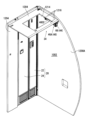
- FIG. 1 is a perspective view of the inside of a lavatory with one side wall and a door of the aircraft lavatory unit of the first embodiment omitted;
- FIG. FIG. 10 is a front view of the door and the front wall located in the closed position and closing the entrance, viewed from the outside of the restroom.
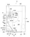
- FIG. 4 is a front view of the door and the front wall located in the closed position and closing the entrance, viewed from the inside of the restroom.
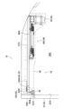
- FIG. 10 is a side view of the power door opening mechanism including the power transmission mechanism as seen from the second side wall inside the restroom with the door positioned at the closed position
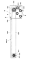
- FIG. 4 is a view of the power door opening mechanism including the power transmission mechanism as seen from below inside the restroom with the door positioned at the closed position
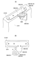
- (A) is a side view of an attached state of an arm that constitutes an engaging member
- (B) is a cross-sectional plan view of a state in which the end of a belt is attached to a roller at the tip of the arm.
- FIG. 4 is a cross-sectional view of a state in which an arm that constitutes an engaging member is rotatably attached to an arm support shaft;
- FIG. 4 is a perspective view of an attached state of an arm that constitutes an engaging member;
- FIG. 4 is a plan view of an attached state of an arm that constitutes an engaging member;
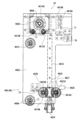
- FIG. 4 is a schematic plan view of the power door opening mechanism including the power transmission mechanism with the door positioned at the closed position;
- FIG. 4 is a schematic plan view of the power door opening mechanism including the power transmission mechanism with the door positioned at the open position;
- FIG. 2 is a perspective view of a front wall with a door closing the doorway of the aircraft lavatory unit, a ceiling wall with a power door opening mechanism attached, and a second side wall connecting the front wall and the ceiling wall.
- 1 is a perspective view of a power door opening mechanism including a power transmission mechanism;
- FIG. 4 is a plan view of an attached state of an arm that constitutes an engaging member;
- FIG. 4 is a schematic plan view of the power door opening mechanism including the power transmission mechanism with the door positioned at the closed position;
- FIG. 4 is
- FIG. 4 is a top view of a power type door opening mechanism including a power transmission mechanism. It is a side view of a power type door opening mechanism including a power transmission mechanism. It is a block diagram showing the configuration of the control system of the power door opening mechanism. 4 is a first flow chart showing the opening/closing operation of the power door opening mechanism; 8 is a second flow chart showing the opening/closing operation of the power door opening mechanism; 4 is a flow chart showing the operation when the door of the power door opening mechanism interferes with a person or an object.
- the schematic plan view of the power door opening mechanism of the second embodiment shows a state where the door is positioned at the closed position.
- the schematic plan view of the power door opening mechanism of the second embodiment shows a state where the door is positioned at the open position.
- FIG. 4 is a plan view showing the relationship between a roller forming an engaged member provided on the first door body and a curved plate forming an engaging member provided on the slider. It is a block diagram showing the configuration of the control system of the power door opening mechanism of the second embodiment.
- the body 12 of the aircraft lavatory unit 10 includes a floorboard 1202, a front wall 1204 and a rear wall 1206 standing from the floorboard 1202 and facing each other, and a front wall 1204 and a rear wall 1206 standing from the floorboard 1202. It includes a first side wall 1208A and a second side wall 1208B (see FIG. 11) connecting both sides of the wall 1206, and a ceiling wall 1210.
- a washbasin 16 is provided on the side wall 1208A, and the inside of the frame 12 serves as a restroom 1002.
- an entrance 1212 of the restroom 1002 is provided on the front wall 1204 so as to be close to the second side wall 1208B, and as shown in FIGS. is opened and closed by
- the door opening/closing mechanism 18 includes a door 20 capable of manually opening and closing the doorway 1212.
- the door 20 is in a closed position to block the doorway 1212 as shown in FIGS. , and an open position to open the port 1212, and is always biased to the closed position.
- door 20 has a width and height corresponding to doorway 1212 .
- the door 20 is a folding door type door composed of two door bodies, a first door body 22 and a second door body 24, which are foldably connected to each other. As shown in FIGS. 2, 3, and 11, with the first door 22 and the second door 24 unfolded, the door 20 is in the closing position for closing the entrance 1212, and as shown in FIG. , the first door 22 and the second door 24 are folded and overlapped inside the restroom 1002, and the door 20 is in the open position to open the doorway 1212. As shown in FIG.
- the portion 26 where the first door 22 and the second door 24 are joined is closer to the restroom than both ends of the door 20 in the width direction when viewed from above. It is displaced away from 1002 . By doing so, it is possible to prevent the first door 22 and the second door 24 from swinging and opening the door 20 due to the load caused by acceleration during landing or takeoff of the aircraft. Make sure you keep your position. It should be noted that the present invention can of course be applied to the case where the first door body 22 and the second door body 24 extend linearly at the closed position of the door 20 when viewed from above. As shown in FIGS.
- first brackets 2202 protrude from the upper and lower ends of the first door body 22 facing the second door body 24, and the second door body 24 is connected to the first door body.
- a second bracket 2402 inserted between the upper and lower first brackets 2202 protrudes. Then, the second bracket 2402 is inserted between the upper and lower first brackets 2202, and the shaft 28 is inserted across the first bracket 2202 and the second bracket 2402, whereby the first door body 22 and the second door body 24 are mounted. and are bendably connected.
- a torsion coil spring 30 is provided over the first bracket 2202 and the second bracket 2402 above and below the second bracket 2402 so that the first door body 22 and the second door body 24 are always positioned at the closed position. are being forced.
- a light leakage cover (not shown) is provided at the end portion where the first door member 22 and the second door member 24 face each other.
- shafts 2204 are provided on the upper and lower end surfaces of the end portion of the first door member 22 located opposite to the second door member 24, and the shafts 2204 move vertically. It is inserted into a hole (not shown) of the mounting frame 32 of the front wall 1204 provided at the end of the entrance 1212 on the side of the second side wall 1208B, and the first door body 22 is supported so as to be able to swing about the shaft 2204. . Further, slide members 2404 are provided on the upper and lower end faces of the end portion of the second door body 24 located opposite to the first door body 22 , and the slide members 2404 are guide rails (not shown) of the mounting frame 32 of the front wall 1204 . , and the slide member 2404 moves along the guide rail when the doorway 1212 is opened or closed.
- the pair of shafts 2204 provided on the first door body 22 are constantly urged by an urging member (not shown) in the direction of insertion into the holes of the mounting frame 32 .
- the pair of shafts 2204 is provided with a pin (not shown) for removal operation capable of moving the pair of shafts 2204 in a direction opposite to the urging direction so as to be operable from outside the restroom 1002. . Therefore, even if the user of the restroom 1002 falls down due to poor physical condition in the restroom 1002 and the user's body interferes with the door 20 positioned at the closed position, the operation pin can be operated.
- the pair of shafts 2204 are removed from the holes of the mounting frame 32, and the sliding member 2404 of the second door 24 is removed from the guide rails, thereby removing the first door 22 and the second door 24 from the outside of the restroom 1002. It is detached from the mounting frame 32 of the front wall 1204 to open the doorway 1212 of the restroom 1002 so that the fallen user can be rescued.
- reference numeral 2002 denotes a display unit indicating that the first door member 22 should be pushed by hand when opening the door 20 from outside the restroom 1002, and reference numeral 2004 in FIG.
- a handle for pulling the door 20 by putting a hand when opening the door 20 is shown.
- a damper (not shown) is provided to suppress the impact when closing the .
- a locking mechanism (not shown) is provided between the second door body 24 moved to the closed position and the front wall 1204 so that the door 20 cannot be opened from the outside when a user enters the restroom 1002.
- Various conventionally known structures can be employed for the connection structure and mounting structure of the first door member 22 and the second door member 24. Of course, it can also be applied to a case in which the door body is composed of a door body.
- the door opening/closing mechanism 18 is provided with a power type door opening mechanism 34 for moving the door 20 from the closed position to the open position.
- the power door opening mechanism 34 includes a non-contact sensor 36 and a human sensor 38 shown in FIG. 17, an engaged member 40 shown in FIGS. , and a control unit 48 shown in FIG.
- the non-contact sensor 36 is a sensor that detects a part of the human body such as a hand, in other words, a sensor that detects a person's hand-holding motion without contact.
- Conventionally known various sensors such as an infrared sensor can be used as the non-contact sensor 36 .
- the non-contact sensors 36 are provided outside and inside the restroom 1002 so that the user of the restroom 1002 can enter and exit the restroom 1002 without touching the door 20 .
- the non-contact sensor 36 is provided on the front wall 1204 on the side of the second door 24 outside and inside the restroom 1002 at a height where a hand can be easily approached.
- the non-contact sensor 36 provided outside the restroom 1002 will be referred to as an outdoor non-contact sensor 36A
- the non-contact sensor 36 provided inside the restroom 1002 will be referred to as an indoor non-contact sensor 36B.
- the time required for the outdoor non-contact sensor 36A and the indoor non-contact sensor 36B to detect the movement of a person's hand is, for example, about 1.5 seconds.
- the human sensor 38 is a sensor that detects a person present inside the restroom 1002 without contact, and is provided on the wall facing the inside of the restroom 1002 or the ceiling wall 1210 .
- Various conventionally known sensors such as an infrared sensor can be used as the human sensor 38 .
- the engaged member 40 is provided at the upper end of the door 20, and is arranged above the door 20 on the inner surface side of the door 20 located in the restroom 1002.
- the engaged member 40 is composed of a roller 5204 supported by the bracket 50 .
- the bracket 50 is attached to the upper end surface of the intermediate portion in the width direction of the first door member 22 .
- the bracket 50 is made of sheet metal. 1 It has an upright plate portion 5004 that projects upward from the door body 22 and an attachment plate portion 5006 that is bent horizontally from the upper end of the upright plate portion 5004 .
- a cam follower 52 is attached to the attachment plate portion 5006 .
- the cam follower 52 includes a support shaft 5202 and a roller 5204 rotatably supported by the support shaft 5202 .
- a nut 5206 is screwed onto the shaft 5202 so that the roller 5204 is rotatably arranged on the mounting plate portion 5006 .
- the roller 5204 is arranged at a location further inside the restroom 1002 than the inner surface 2210 of the first door member 22, and at a location above the first door member 22 as shown in FIG. ing.
- An engaged plate portion projecting upward from the mounting plate portion 5006 of the bracket 50 may be provided, and the engaged member 40 may be configured by the engaged plate portion. This is advantageous for smooth engagement with an engaging member 42, which will be described later.
- the engaging member 42 is provided above the door 20 in the restroom 1002, and the roller 5204 moves from the first door body 22 side to the open position of the door 20 from the closed position of the door 20 to the open position of the door 20. can be engaged with the first door body 22, and is provided in an open shape in a direction away from the first door body 22. - ⁇ Since the engagement member 42 is provided in this manner, when the door 20 is manually opened, the roller 5204 provided on the first door body 22 and moving integrally with the first door body 22 is not attached to the engagement member 42. The door 20 moves away from the doorway 1212 without interference. Therefore, even if the power door opening mechanism 34 is provided, the operation of manually moving the door 20 from the closed position to the open position is performed smoothly.
- the engaging member 42 swings in the horizontal direction toward and away from the entrance/exit 1212 around the arm support shaft 4202 whose axial center is oriented in the vertical direction. It is composed of a movable arm 42A.
- the arm 42A has a length approximately equal to the width of the first door 22, and is one end in the longitudinal direction of the arm 42A via the arm support shaft 4202.
- the base end is swingably supported by the ceiling wall 1210, and the arm support shaft 4202 is arranged near the support shaft 2204 of the first door body 22 and near the second side wall 1208B.
- the arm 42A is made of sheet metal, and as shown in FIGS.
- the arm 42A is in the initial position extending substantially parallel to the first door body 22 when the door 20 is closed, and when the door 20 is open as shown in FIG. The open position extends parallel to the first door body 22 .
- the bending plate portion 4206 is arranged between the inner surface 2210 of the first door member 22 and the roller 5204 in plan view.
- the portion 4206 is arranged in contact with the roller 5204 from the first door member 22 side, or arranged close to the roller 5204 .
- a first collar 4210 and a second collar 4212 are provided on the lower surface of the body plate portion 4204 at the tip, which is the other end in the longitudinal direction of the arm 42A.
- a roller 4214 sandwiched between is rotatably provided via a support shaft 4216 and a nut 4218 .
- this roller 4214 is attached to one end in the longitudinal direction of a belt 4604 constituting a belt/pulley mechanism 46A, which will be described later, by a pair of attachment pieces 4220 and 4222.
- One end in the longitudinal direction of 4604 is rotatably attached to the tip of arm 42A via roller 4214 .
- the arm support shaft 4202 is supported via the arm bracket 54, and the arm bracket 54 is attached to the ceiling wall 1210 via the pressing plate 56 and a plurality of bolts B.
- the arm bracket 54 is made of metal and includes an upper plate portion 5402 and a lower plate portion 5404 facing each other, and a side plate portion 5406 connecting the upper plate portion 5402 and the lower plate portion 5404 together. It is optional to provide the arm bracket 54 integrally with the support frame 4602 described later.
- the ceiling wall 1210 is sandwiched between the pressing plate 56 and the upper plate portion 5402 by a plurality of bolts B, whereby the arm bracket 54 is attached to the ceiling wall 1210. As shown in FIGS.
- the side plate portion 5406 is It abuts on the second side wall 1208B. Therefore, the arm 42A is swingably supported by the ceiling wall 1210 via the arm support shaft 4202 and the arm bracket 54.
- the arm support shaft 4202 is configured by a bolt with a square hole, and is inserted through the bolt insertion hole of the lower plate portion 5404 from below the lower plate portion 5404.
- the arm support shaft 4202 is attached to the arm bracket 54 by coupling to the internal thread of the arm.
- the base end in the longitudinal direction of the main body plate portion 4204 of the arm 42A is rotatable via a bearing 58 between the upper plate portion 5402 and the lower plate portion 5404 at the position of the arm support shaft 4202 near the upper plate portion 5402. It is supported by a support shaft 4202 for use.
- a coil portion 6202 of the torsion coil spring 62 is wound around the arm support shaft 4202 below the bearing 58 via upper and lower washers 60A and 60B.
- the portion 6206 abuts on a pin 5410 provided on the lower plate portion 5404 and urges the arm 42A so that the arm 42A is always positioned at the initial position.
- reference numeral 64 denotes an initial position stopper which is provided on the lower plate portion 5404 of the bracket 50 and contacts the bending plate portion 4206 to determine the initial position of the arm 42A.
- the bent plate portion 4206 swings the first door body 22 via the roller 5204, thereby causing the door to open. 20 is in the open position shown in FIG.
- the biasing force of the torsion coil spring 30 provided on the door 20 and the torsion coil spring 62 wound around the arm support shaft 4202 causes the arm 42A and the first door body to move. 22 swings, and as shown in FIG. 11, the arm 42A returns to its initial position and the door 20 returns to its closed position.
- the actuator 44 is an electric motor 66 (stepping motor), and the power transmission mechanism 46 includes a belt/pulley mechanism 46A. ing. 5, 6, 7A, 14, 15 and 16, the belt 4604 is omitted for clarity of the belt/pulley mechanism 46A.
- the belt/pulley mechanism 46A is provided above the door 20 in the restroom 1002, and the belt/pulley mechanism 46A and the electric motor 66 are positioned close to the ceiling wall 1210 as shown in FIGS. 14 and attached to the ceiling wall 1210 via a single support frame 4602 shown in FIG.
- the support frame 4602 is made of a metal plate, and is attached to the lower surface of the ceiling wall 1210 near the second side wall 1208B as shown in FIGS.
- reference numeral 1214 denotes an opening provided in the ceiling wall 1210 for arranging a lighting fixture
- reference numeral 1216 denotes an end portion of a bolt that joins the support frame 4602 and the ceiling wall 1210 together.
- the electric motor 66 is provided at the end of the support frame 4602 on the side of the back wall 1206 in the longitudinal direction, near the second side wall 1208B.
- the belt and pulley mechanism 46A includes a belt 4604, a toothed drive pulley 4606, a first toothed guide pulley 4608 and a second toothed guide pulley 4610, as shown in FIGS. , a pair of rollers 4612A and 4612B, and a pair of toothed moving pulleys 4614A and 4614B.
- the shaft centers of the toothed drive pulley 4606, the toothed first guide pulley 4608, the toothed second guide pulley 4610, the pair of rollers 4612A and 4612B, and the pair of toothed moving pulleys 4614A and 4614B are oriented vertically, In other words, it extends in the vertical direction, and the vertical dimension of the belt/pulley mechanism 46A is shortened, in other words, the vertical dimension of the power transmission mechanism 46 is shortened.
- a toothless belt may be used as the belt 4604 and a toothless pulley may be used as the pulley.
- a toothed belt is used and the pulleys are a toothed drive pulley 4606, a first toothed guide pulley 4608, a second toothed guide pulley 4610, and a pair of toothed transfer pulleys 4614A, 4614B.
- One longitudinal end 4604A of the belt 4604 is rotatably attached to the longitudinal tip of the arm 42A via a pair of attachment pieces 4220 and 4222 as described with reference to FIG. 7B. ing.
- the other longitudinal end 4604B of the belt 4604 is clamped and fixed on the support frame 4602 by a pair of mounting pieces 4616A and 4616B, as shown in FIGS. As shown in FIG.
- the toothed drive pulley 4606 is attached to the output shaft 6602 of the electric motor 66, and the output shaft 6602 extends vertically.
- the support frame 4602 is attached with a rail 4618 extending linearly in the front-rear direction of the restroom 1002, and a moving bracket 4620 is provided movably along the rail 4618.
- a pair of toothed displacement pulleys 4614A, 4614B are rotatably supported on shafts 4622A, 4622B attached to this displacement bracket 4620 such that the pair of toothed displacement pulleys 4614A, 4614B are aligned along rails 4618. Reciprocating linear movement is possible together.
- the moving bracket 4620 has a rear end position where the pair of toothed moving pulleys 4614A and 4614B is farthest from the entrance/exit 1212, FIGS.
- a pair of toothed moving pulleys 4614A, 4614B are reciprocally linearly movable between the front end positions closest to the entrance/exit 1212.
- a constant load spiral spring 4624 is provided at the end of the support frame 4602 near the front wall 1204 in the longitudinal direction. and urges the moving bracket 4620 so that the moving bracket 4620 is always positioned at the front end position.
- the belt 4604 is constantly under tension.
- the first toothed guide pulley 4608 is positioned on the support frame 4602 adjacent to the roller 4214 at the tip of the arm 42A in the open position of the arm 42A and adjacent to the second side wall 1208B. placed in place.
- a second toothed guide pulley 4610 is located at a portion of the support frame 4602 adjacent to the pair of rollers 4612A, 4612B and adjacent to the second side wall 1208B.
- a belt 4604 having the other end 4604B clamped and fixed on a support frame 4602 by a pair of mounting pieces 4616A and 4616B is hung on a pair of toothed transfer pulleys 4614A and 4614B.
- one end 4604A of the belt 46 is attached to the tip of the arm 42A via a pair of attachment pieces 4220 and 4222.
- the power transmission mechanism 46 including the belt/pulley mechanism 46A and the actuator 44 including the electric motor 66 are attached to the ceiling wall 1210 near the second side wall 1208B via the support frame 4602. , the power transmission mechanism 46 and the actuator 44 are arranged close to the second side wall 1208B, and the power door opening mechanism 34 excluding the electric motor 66 is located above the door 20 as shown in FIG. are placed in
- the arm 42A when the door 20 is closed, the arm 42A is in its initial position, and the pair of toothed transfer pulleys 4614A and 4614B are in their rear end positions.
- the electric motor 66 When the electric motor 66 is rotated forward at the closed position of the door 20, the belt 4604 attached to the tip of the arm 42A moves forward in the direction of the back wall 1206 away from the doorway 1212 due to the forward rotation of the toothed drive pulley 4606. Pulled, the arm 42A moves from the initial position toward the open position.
- the pair of toothed moving pulleys 4614A and 4614B are moved from the rear end position to the front end position by the biasing force of the constant load spiral spring 4624, and the other end is moved by the pair of mounting pieces 4220 and 4222 on the support frame 4602.
- the belt 4604 does not flex, and between the other end 4604B of the belt 4604 and the toothed drive pulley 4606, the belt 4604 12 from the initial position, and the door 20 is in the open position.
- the belt 4604 attached to the tip of the arm 42A is drawn toward the back wall 1206 by a stroke twice the moving stroke of the pair of toothed moving pulleys 4614A and 4614B, and the door 20 is moved from the closed position. Open position.
- a pair of toothed moving pulleys 4614A and 4614B are provided as the toothed moving pulleys, but the number of toothed moving pulleys may be one, or three or more. good too.
- the door 20 is urged to move to the closed position by the torsion coil spring 30 provided on the door 20, and the arm 42A is urged to return to the initial position by the torsion coil spring 62 provided on the arm 42A. energized.
- the amount of belt 4604 extended to the tip of arm 42A is small, belt 4604 restrains the movement of arm 42A to the initial position.
- the roller 5204 forming the engaged member 40 engages with the bent plate portion 4206 of the arm 42A forming the engaging member 42, so that the movement of the door 20 to the closing position is restrained.
- the door 20 is held by the torsion coil spring provided on the door 20. 30 and the urging force of the torsion coil spring 62 provided on the arm 42A, the arm 42A swings according to the amount of belt 4604 extended by the reverse rotation of the toothed drive pulley 4606, and silently reaches the closed position. . Therefore, the belt 4604 is extended to the arm 42A with a stroke that is twice the movement stroke of the pair of toothed movement pulleys 4614A and 4614B, and the door 20 is moved from the open position to the closed position.
- the power transmission mechanism 46 has a compact structure that does not take up much space in the front-rear direction of the restroom 1002 .
- the door 20 is urged to move to the closed position by the urging force of the torsion coil spring 30 provided on the door 20, and a damper (not shown) is provided to suppress the impact when the doorway 1212 is closed. Therefore, the operation of reversing the electric motor 66 at the open position of the door 20 may be omitted. In this case, instead of rotating the electric motor 66 in reverse, the supply of the drive signal from the control unit 48 to the electric motor 66 is stopped. A free state in which the output shaft 6602 is rotatable is sufficient. However, when the electric motor 66 is reversed in the open position of the door 20, the movement speed of the door 20 from the open position to the closed position can be performed at a desired speed, and the door 20 moves vigorously to the closed position. This is advantageous in suppressing impact and noise generated by movement, and is advantageous in giving the aircraft lavatory unit 10 a high-class appearance.
- a decorative plate 68 is provided to cover the arm 42A, the power transmission mechanism 46, and the electric motor 66 that constitute the engaging member 42 from below the restroom 1002 and hide the upper portion of the bracket 50, the roller 5204, the arm 42A, and the power transmission mechanism 46. They are designed so that the user of the aircraft lavatory unit 10 cannot see them, and the beauty of the lavatory 1002 is ensured.
- the decorative plate 68 is made of synthetic resin, and is attached to the front wall 1204 in the front-to-rear direction of the restroom 1002 and to the ceiling wall 1210 near the rear wall 1206. In one direction, it is attached to the second side wall 1208B, and in the other width direction of the restroom 1002, it is erected and attached to the ceiling wall 1210. As shown in FIG. As shown in FIG. 11 , the decorative plate 68 is provided with a long groove 6802 through which the upper portion of the bracket 50 protrudes above the restroom 1002 . The long groove 6802 extends along the locus of movement of the upright plate portion 5004 of the bracket 50 that moves along with the movement of the first door body 22 between the closed position and the open position, so that the bracket 50 can move smoothly.
- the engaged member 40 (roller 5204) can be smoothly moved, and the arm 42A can be smoothly swung between the initial position and the open position.
- the inclination angle ⁇ of the standing plate portion 5004 of the bracket 50 with respect to the first door body 22 is determined so that the width of the long groove 6802 is minimized.
- a door close detection piece 4626 On both sides of the movement bracket 4620 in the direction in which the pair of toothed movement pulleys 4614A and 4614B are arranged, a door close detection piece 4626, a near point detection piece 4627, and a door open detection piece are provided. 4628 are projected.
- the support frame 4602 is provided with a door close sensor 70 , a near-point dog sensor 71 , and a door open sensor 72 .
- the door closing sensor 70 detects the door closing detection piece 4626 when the arm 42A is in the initial position and the pair of toothed moving pulleys 4614A and 4614B is in the rear end position, in other words, when the door 20 is closed. is provided as follows.
- the near-point dog sensor 71 is provided to detect that the electric motor 66 has returned just before the origin position.
- the origin position of the electric motor 66 corresponds to a state where the pair of toothed moving pulleys 4614A and 4614B are positioned slightly rearward from the rear end position.
- the control unit 48 controls the electric motor 66 to stop based on the detection result of the near-point dog sensor 71, so that the electric motor 66 is accurately returned to the origin position.
- the amount of rotation of the electric motor 66 is controlled based on this origin position. As will be described later, whether or not the arm 42A has reached the open position and the door 20 has reached the open position is determined by the control unit 48 based on the amount of rotation from the origin position when the electric motor 66 rotates forward. do.
- the amount of rotation is detected by an encoder 67, which will be described later.
- the door open sensor 72 is provided to detect an abnormality that occurs while the electric motor 66 is rotating forward to move the door 20 to the open position. That is, after the arm 42A is at the open position due to the forward rotation of the electric motor 66, the electric motor 66 continues to rotate forward, and the pair of toothed moving pulleys 4614A and 4614B is moved to the front end position corresponding to the open position of the door 20.
- the door open sensor 72 is provided to detect the door open detection piece 4628 when reaching the limit position exceeding .
- the control unit 48 determines that an abnormality has occurred, and performs abnormality processing such as stopping the forward rotation of the electric motor 66.
- FIG. In the following description, the detection operation of the door open sensor 72 and the abnormality processing associated with the detection operation will be omitted.
- the door close sensor 70, the near-point dog sensor 71, and the door open sensor 72 are composed of photointerrupters, for example.
- the control unit 48 controls the electric motor 66 based on detection signals from the human sensor 38, the outdoor non-contact sensor 36A, the indoor non-contact sensor 36B, the door closing sensor 70, and the near-point dog sensor 71. It controls reverse rotation, energization, discontinuation of energization, etc. Specifically, it controls the rotation amount (rotation angle) and rotation speed of the electric motor 66 (stepping motor).
- the electric motor 66 is provided with an encoder 67 that detects the rotation amount (rotation angle) of the electric motor 66 to generate a rotation amount detection signal and supplies the signal to the control unit 48 .
- the controller 48 controls the electric motor 66 based on the rotation detection signal supplied from the encoder 67 . Control of the electric motor 66 by the controller 48 controls the movement of the arm 42A between the initial position and the open position, and thus the movement of the door 20 between the closed position and the open position.
- FIG. 18 the operation of the power door opening mechanism 34 of this embodiment will be described with reference to the flow charts of FIGS. 18 to 20.
- FIG. 18 the operation of the power door opening mechanism 34 of this embodiment will be described with reference to the flow charts of FIGS. 18 to 20.
- step S10 determines whether or not the detection signal of the human sensor 38 is turned on (detected), in other words, whether or not a person (user) exists inside the restroom 1002 (step S10). If step S10 is affirmative, the process proceeds to step S30, which will be described later. If step S10 is negative, the controller 48 determines whether or not the detection signal of the outdoor non-contact sensor 36A is turned on (step S12).
- step S12 In order to use the restroom 1002, the user of the restroom 1002 puts his hand over the outdoor non-contact sensor 36A to turn on the outdoor non-contact sensor 36A. If step S12 is affirmative, that is, when the detection signal of the outdoor non-contact sensor 36A is turned on, the control unit 48 rotates the electric motor 66 forward, thereby moving the door 20 to the open position via the power transmission mechanism 46. It is moved (step S14). Based on the rotation amount detection signal supplied from the encoder 67, the control unit 48 determines whether the amount of rotation of the electric motor 66 has reached the commanded amount of movement sufficient to move the door 20 to the open position. It is determined whether or not the movement to is completed (step S16).
- step S16 If step S16 is negative, the control unit 48 returns to step S16 to continue forward rotation of the electric motor 66 . If step S16 is affirmative, the door 20 has moved to the open position, so the control unit 48 stops the electric motor 66 to maintain the door 20 in the open position (step S18).
- the control unit 48 determines whether or not the first predetermined time T1 has passed since the motion sensor 38 was turned on and the door 20 moved to the open position (step S20).
- the first predetermined time T1 is, for example, 9 seconds.
- the user enters the restroom 1002 while the door 20 is moved to the open position. Therefore, the control unit 48 moves the door 20 from the open position to the closed position by the electric motor 66 when the first predetermined time T1 has elapsed while the human sensor 38 is on and the door 20 is at the open position. will be moved. If step S20 is affirmative, the controller 48 reverses the electric motor 66, thereby moving the door 20 to the closed position via the power transmission mechanism 46 (step S24).
- step S20 it is determined whether the human sensor 38 is on and the indoor non-contact sensor 36B is on (step S22). If step S22 is negative, the process returns to step S20. If step S22 is affirmative, the controller 48 reverses the electric motor 66, thereby moving the door 20 to the closed position via the power transmission mechanism 46 (step S24). In other words, the control unit 48 activates the actuator 44 (electric A motor 66) moves the door 20 from the open position to the closed position. That is, when the user who has entered the restroom 1002 wants to immediately move the door 20 from the open position to the closed position, the door 20 is moved to the closed position by placing his or her hand over the indoor non-contact sensor 36B.
- step S26 determines whether the human sensor 38 is on and the door closing sensor 70 is on. If step S26 is negative, the control unit 48 repeats step S26 to move the door 20 to the closing position. If step S26 is affirmative, the control unit 48 stops the electric motor 66 and maintains the door 20 in the closed position because the door 20 has moved to the closed position (step S28). By maintaining the door 20 in the closed position in this way, the user can use the restroom 1002 .
- step S30 determines whether or not the human sensor 38 is on for detection and the indoor non-contact sensor 36B is on for detection. If step S30 is negative, the control unit 48 returns to step S30 and keeps the door 20 in the closed position because the user is using the restroom 1002 . Therefore, if the human sensor 38 is on for detection, the controller 48 controls the actuator 44 (electric motor 66) regardless of whether or not the outdoor non-contact sensor 36A is detected unless the indoor non-contact sensor 36B is on for detection. is prohibited from moving the door 20 from the closed position to the open position. By maintaining the door 20 in the closed position and prohibiting the movement of the door 20 to the open position in this manner, the state in which the user can use the restroom 1002 is maintained.
- step S30 the controller 48 rotates the electric motor 66 forward to move the door 20 to the open position (step S32). Therefore, when the human sensor 38 is on for detection, the door closing sensor 70 is on for detection (already determined in step S26), and the indoor non-contact sensor 36B has detected, The actuator 44 (electric motor 66) moves the door 20 from the closed position to the open position.
- step S34 determines whether or not the human sensor 38 is turned on and the movement of the electric motor 66 by the designated movement amount is completed (that is, whether or not the door 20 is positioned at the open position) (step S34). ). If step S34 is negative, step S34 is repeated to move door 20 to the open position. If step S34 is affirmative, the door 20 has moved to the open position, so the electric motor 66 is stopped and the door 20 is maintained in the open position (step S36). In this state, the user in the restroom 1002 leaves the restroom 1002 .
- the control unit 48 determines whether or not the second predetermined time T2 has elapsed while the human sensor 38 is in the detection-off (no detection) state (step S38).
- the second predetermined time T2 is, for example, 9 seconds. If step 38 is affirmative, the controller 48 reverses the electric motor 66 to move the door 20 to the closing position (step S40). Next, the controller 48 determines whether the human sensor 38 is off and the door closing sensor 70 is on (step S42). If step S42 is negative, step S42 is repeated to move the door 20 to the closing position. If step S42 is affirmative, the control unit 48 stops the electric motor 66 to maintain the door 20 in the closed position because the door 20 has moved to the closed position without the user in the restroom 1002 (step S42).
- step S44 the process returns to step S10 to return to the initial state.
- the control unit 48 causes the actuator 44 (electric motor 66) to open the door 20 when the second predetermined time T2 has elapsed while the human sensor 38 is off and the door 20 is at the open position. It is moved from the open position to the closed position (steps S34, S36, S38, S40, S42, S44).
- step 38 it is determined whether or not the human sensor 38 is on for detection (step S46). That is, it is determined whether or not another user has entered the restroom 1002 . If step S46 is negative, the process returns to step S38 to determine whether or not the second predetermined time T2 has elapsed. If step S46 is affirmative, it is determined whether or not the human detection sensor 38 is ON and the third predetermined time T3 has elapsed (step S48). The third predetermined time T3 is, for example, 9 seconds. If step S48 is negative, step S48 is repeated.
- step S48 determines whether the human sensor 38 is on and the door closing sensor 70 is on (step S52). If step S52 is negative, step S52 is repeated to move the door 20 to the closing position. If step S52 is affirmative, control unit 48 returns to step S28 because another user is present in restroom 1002, and repeats the same processing thereafter. In other words, the control unit 48 controls the actuator 44 (electric motor 66) moves the door 20 from the open position to the closed position (steps S34, S36, S38, S46, S48, S50, S52).
- the user uses the restroom 1002 by repeating such a series of operations.
- the control unit 48 controls a command position P1, which is the amount of rotation to be commanded to the electric motor 66 when the door 20 moves from the closed position to the open position, and a feedback position P2, which is the actual amount of rotation detected by the encoder 67. is monitored, and it is determined whether or not the difference ⁇ P is equal to or greater than a predetermined threshold value Pt (step S100).
- the threshold value Pt is, for example, 5 mm when converted into the amount of movement of the pair of toothed moving pulleys 4614A and 4614B. If the difference ⁇ P is equal to or greater than the threshold value Pt, it can be determined that the door 20 is not moving normally and that the moving door 20 has interfered with a person or object.
- step S100 If step S100 is negative, the following processing is skipped. If step S100 is affirmative, the control unit 48 stops energizing the electric motor 66 (step S102). As a result, the electric motor 66 becomes free to rotate, and the driving force applied to the door 20 from the electric motor 66 via the power transmission mechanism 46 becomes zero. In other words, the electric motor 66 becomes free to rotate. In this state, the door 20 is moved to the closed position by the biasing force of the torsion coil spring 30 of the door 20, and the arm 42A is returned to the initial position by the biasing force of the torsion coil spring 62. FIG.
- the door closing detection piece 4626 is moved to a position where it can be detected by the door closing sensor 70 . That is, the controller 48 determines whether or not the door closing sensor 70 is turned on (step S104).
- step S104 is negative, step S104 is repeated. If step S104 is affirmative, the control unit 48 starts energizing the electric motor 66 (rotation command) and gives a command to the electric motor 66 to return to the origin position (step S106). This causes the electric motor 66 to rotate in reverse. Next, the control unit 48 determines whether the detection of the near-point dog sensor 71 is turned on (step S108). If step S108 is negative, step S108 is repeated. If step S108 is affirmative, the control unit 48 stops the reverse rotation of the electric motor 66 and controls the stop of the electric motor 66 . As a result, the electric motor 66 returns to the origin position (step S110).
- the control unit 48 controls the electric motor 66. , and the driving force applied from the electric motor 66 to the door 20 is set to zero, so that people and objects are protected from the door 20.
- the arm 42A moved to the open position is not engaged with the roller 5204, so that the belt 4604 is drawn out in the direction of the doorway 1212 by the reverse rotation of the electric motor 66.
- the arm 42A is moved from the open position to the initial position by the biasing force of the torsion coil spring 62 and is maintained at the initial position.
- the control unit 48 maintains the state in which the electric motor 66 is stopped by executing step S30. Therefore, the worker can perform maintenance, cleaning, etc. inside the restroom 1002 with the door 20 fixed at the open position.
- the door 20 After maintenance, cleaning, or the like, the door 20 is released from the latch and moved to the closed position by the biasing force of the torsion coil spring 30, after which the restroom 1002 can be used normally. becomes possible. Specifically, the door 20 is moved to the closed position by the biasing force of the torsion coil spring 30, and the processes from step S30 onward in FIGS. 18 and 19 are executed. After the employee leaves the restroom 1002, the control unit 48 returns to the process of step S10, and the restroom 1002 is ready for normal use. Alternatively, after the door 20 is manually moved to the open position, the door 20 may be fixed at the open position by a latch. In that case, since the arm 42A is maintained at the initial position by the biasing force of the torsion coil spring 62 from the beginning without moving to the open position, the operation of moving the arm 42A from the open position to the initial position is unnecessary.
- both the outdoor non-contact sensor 36A and the indoor non-contact sensor 36B are simultaneously operated by holding hands over the indoor and outdoor non-contact sensors.
- the control unit 48 switches the functions of the electric motor 66 and the control unit 48 between invalid and valid. Disabling the function of the electric motor 66 means stopping power supply to the electric motor 66 , and enabling the function of the electric motor 66 means starting power supply to the electric motor 66 .
- the predetermined time is 120 seconds
- the predetermined time is 20 seconds
- the time required for the operation of placing a hand over each non-contact sensor is set to a longer time, such as 20 to 120 seconds, compared to the time required for opening and closing the door 20, for example, about 1.5 seconds. This prevents the functions of the electric motor 66 and the control unit 48 from being inadvertently switched between invalid and valid due to an erroneous operation by a normal user (passenger).
- the functions of the electric motor 66 and the control unit 48 Since it is necessary to switch the functions of the electric motor 66 and the control unit 48 from ineffective to effective, the functions of the outdoor non-contact sensor 36A and the indoor non-contact sensor 36B and the operation of the control unit 48 for making these sensors function is always enabled. Therefore, the functions of the electric motor 66 and the controller 48 can be easily disabled or enabled by a simple operation such as placing a hand over both the outdoor non-contact sensor 36A and the indoor non-contact sensor 36B at the same time. is planned.
- the control unit 48 detects the motion of the outdoor non-contact sensor 36A that detects the movement of a person holding his/her hand in a non-contact manner. is turned on, the actuator 44 moves the door 20 from the closed position to the open position. Therefore, the user of the lavatory 1002 can open the door 20 simply by placing his or her hand over the outdoor non-contact sensor 36A without touching the door 20 or the contact sensor, which is advantageous in preventing infection with the novel coronavirus in the cabin. becomes. Further, unless the user intentionally holds his or her hand over the outdoor non-contact sensor 36A, the outdoor non-contact sensor 36A does not detect the hand. Even if a crew member stops and works near the non-contact sensor 36A, the outdoor non-contact sensor 36A does not perform a detection operation. be advantageous.
- the control unit 48 controls whether or not the outdoor non-contact sensor 36A detects the door 20 from the closed position by the outdoor non-contact sensor 36A. Prohibited to move to open position. Therefore, when there is a user inside the restroom 1002, even if the user outside the restroom 1002 puts his hand over the outdoor non-contact sensor 36A and the outdoor non-contact sensor 36A detects yes, the door 20 is erroneously detected. erroneous operation in which the door is opened can be suppressed, which is advantageous in improving the usability of the restroom 1002 .
- the control unit 48 causes the actuator 44 to open the door 20 when the first predetermined time T1 has elapsed since the human sensor 38 detected the door 20 and the door 20 was positioned at the open position. It was made to move from the position to the closed position. Therefore, after the user enters the room, the door 20 automatically closes when the first predetermined time T1 elapses, so the user does not need to touch the door 20 or the contact sensor. Needless to say, this is advantageous, and since the user does not need to perform any special operation, it is advantageous in terms of improving usability of the restroom 1002 .
- the control unit 48 when the human sensor 38 is detected, the door 20 is in the open position, and the indoor non-contact sensor 36B is detected, the control unit 48 , the actuator 44 moves the door 20 from the open position to the closed position. Therefore, after the user enters the room, the door 20 can be closed by holding the hand over the indoor non-contact sensor 36B. In addition, the user does not need to wait for a wasteful time, and the door 20 can be closed immediately, which is advantageous in improving the usability of the restroom 1002. becomes.
- the control unit 48 moves the door 20 from the closed position to the open position. Therefore, the user present inside the restroom 1002 can open the door 20 by placing his or her hand over the indoor non-contact sensor 36B. Needless to say, it is advantageous in preventing corona infection, and the user does not have to wait for a waste of time, and the door 20 can be opened immediately, so that the convenience of the restroom 1002 can be improved. It is advantageous in planning.
- control unit 48 causes the actuator 44 to open the door 20 when the second predetermined time T2 has passed without detection by the human sensor 38 and the door 20 is in the open position. Moved from the open position to the closed position. Therefore, after the user leaves the restroom 1002, the door 20 automatically closes when the second predetermined time T2 elapses without the user existing in the restroom 1002. 20 or the contact sensor, which is of course advantageous in terms of preventing infection with the novel coronavirus in the cabin. It is advantageous in planning.
- the control unit 48 causes the actuator to 44 moves the door 20 from the open position to the closed position. Therefore, after the user who was using the lavatory 1002 leaves the room, the next user who has been waiting enters the room, and when the third predetermined time T3 has passed since the presence of the detection of the human sensor 38, Since the door 20 is closed immediately, the next user does not need to touch the door 20 or the contact sensor, which is advantageous in preventing infection of the new corona in the aircraft. Since there is no need to carry out the cleaning, it is advantageous in improving the usability of the restroom 1002 .
- the door 20 is automatically closed after the third predetermined time T3 has elapsed. will make it work. In that case, if the same user intends to use the restroom 1002 again, the restroom 1002 can be used as intended.
- the same user holds his or her hand over the indoor non-contact sensor 36B again to open the door 20 as intended and leave the room. can be done. Therefore, it is advantageous in improving the usability of the restroom 1002 .
- control unit 48 energizes the electric motor 66 when the door 20 cannot be moved normally due to interference of a person or an object with the door 20 while the door 20 is moving. is cut off, and the driving force applied to the door 20 from the electric motor 66 is set to zero. Therefore, if the door 20 interferes with a person or an object while the door 20 is moving from the closed position to the open position, the driving force of the electric motor 66 becomes zero, and the application of force from the door 20 to the person or object is stopped. Therefore, it is advantageous in protecting people and objects from the door 20.
- the door 20 during movement interferes with a person or an object, it is determined whether the user is inside or outside the restroom 1002 and whether or not the user intends to use the restroom 1002 from now on ( Depending on whether the restroom 1002 is used before or after use, the following four usage situations occur. 1) If a user exists inside the restroom 1002 and has the intention of using the restroom 1002 from now on, the user must use the restroom 1002 as intended. becomes possible. 2) When the user has left the restroom 1002 and intends to use the restroom 1002, the user holds his or her hand over the outdoor non-contact sensor 36A. After moving the door 20 to the open position, it becomes possible to enter the restroom 1002 and use the restroom 1002 .
- FIG. 21 differs from the first embodiment in that an electric linear actuator 74 is used as the actuator 44 and the power transmission mechanism 46 is omitted.
- the electric linear actuator 74 includes an elongated shaft 7402 and a slider 7404 which is movable along the longitudinal direction of the shaft 7402 and is non-rotatable around the axis of the shaft 7402.
- the electric linear actuator 74 is arranged above the door 20 and closer to the second side wall 1208B.
- the shaft 7402 has magnets aligned along its length, each magnet having north and south poles that alternate along the length of the shaft 7402 .
- the base end which is one end in the longitudinal direction of the shaft 7402, is horizontally swingable on a support shaft 7410 arranged near the second side wall 1208B and near the ceiling wall 1210 with its axis directed vertically.
- the tip which is the other longitudinal end of the supported shaft 7402 , extends in the direction of the port 1212 .
- the support shaft 7410 is attached to the ceiling wall 1210 .
- the slider 7404 has a built-in coil, and when a drive signal is supplied to the coil from the control unit 48, the magnetic field generated in the coil and the magnetic field of each magnet generate a magnetic interaction.
- the slider 7404 reciprocates linearly along the longitudinal direction of the shaft 7402 , in other words, moves toward and away from the doorway 1212 .
- an encoder 75 that detects the amount of movement of the slider 7404 and supplies a movement amount detection signal to the controller 48 .
- the outdoor non-contact sensor 36A, the indoor non-contact sensor 36B, the door close sensor 70, the near-point dog sensor 71, and the door open sensor are similar to those in the first embodiment.
- 72, a human sensor 38, and a control unit 48 are provided.
- the control unit 48 controls the movement direction and movement stroke of the slider 7404 by supplying the coil of the slider 7404 with a drive signal generated based on the detection signal of each sensor.
- the engaged member 40 is positioned above the door 20 on the inner surface side of the door 20 located in the restroom 1002, as in the first embodiment. are doing.
- a bracket 50 is provided at the upper end of the first door body 22 , and the engaged member 40 is composed of a roller 5204 provided on a mounting plate portion 5006 of this bracket 50 .
- a curved plate 76 is provided on the lower surface of the slider 7404 so as to extend in a curved shape and constitute the engaging member 42 .
- the curved plate 76 is provided above the door 20 in the restroom 1002 and is engageable with the roller 5204 from the door 20 side from the closed position of the door 20 to the open position of the door 20, and moves away from the door 20. is provided in an open manner.
- a decorative plate 68 is provided to cover the electric linear actuator 74 from below as in the first embodiment.
- a long groove 6802 is provided that extends along the movement locus of the upright plate portion 5004 of the bracket 50 that moves along with the movement of the first door body 22 between the positions and allows the bracket 50 to move smoothly (Fig. 11).
- the first door body 22 and the second door body 24 are overlapped at the open position of the door 20
- the slider 7404 is at the open position
- the first door body 22 and the second door body 24 are overlapped.
- the tip side portion of the shaft 7402 and the slider 7404 are positioned on the .
- the movement of the door 20 from the open position to the closed position is the movement of the roller 5204 in the direction toward the doorway 1212 because the roller 5204 engages with the curved plate 76, and the movement of the door 20 toward the door.
- the movement of the roller 5204 from the open position to the closed position is constrained by the curved plate 76, resisting the urging force of the torsion coil spring 30 provided on the door 20, and the movement of the roller 5204 in the direction toward the entrance 1212 and the door 20. is moved from the open position to the closed position according to the amount of movement of the slider 7404 along the longitudinal direction of the shaft 7402, and the door 20 silently moves to the closed position.
- the door 20 is urged to move to the closed position by the urging force of the torsion coil spring 30 provided on the door 20, and a damper (not shown) is provided to suppress the impact when the doorway 1212 is closed.
- the control unit 48 stops supplying the drive signal to the slider 7404. is made free to move along the shaft 7402 .
- the electric linear actuator 74 is used instead of the electric motor 66 for the normal operation when the user uses the restroom 1002 and the operation when the door 20 interferes with a person or object. 18, 19, and 20 except that the power transmission mechanism 46 is used and the power transmission mechanism 46 is omitted.
- the functions of the electric motor 66 and the control unit 48 are forcibly disabled or enabled.
- the operation in this case is also the same as the operation described in the first embodiment, except that the electric linear actuator 74 is used instead of the electric motor 66 and the power transmission mechanism 46 is omitted.
- the same effects as those of the first embodiment can be obtained by such a second embodiment, and since the power transmission mechanism 46 is omitted in the second embodiment, the power transmission mechanism 46 is different from that of the first embodiment. This is more advantageous in reducing the weight of the power door opening mechanism 34.
- the present invention can of course be applied to a case where the door 20 that opens and closes the doorway 1212 of the restroom 1002 is composed of a single door that can be opened and closed.
- Aircraft Lavatory Unit 1002 Lavatory 12 Frame 1202 Floor Board 1204 Front Wall 1206 Rear Wall 1208A First Side Wall 1208B Second Side Wall 1210 Ceiling Wall 1212 Doorway 1214 Opening 1216 Bolt End 14 Toilet 16 Washstand 18 Door Opening and Closing Mechanism 20 Door 2002 Display 2004 Handle 22 First door 2202 First bracket 2204 Axis 2210 Inner surface 24 Second door 2402 Second bracket 2404 Slide member 26 Joined part 28 Axis 30 Torsion coil spring 32 Mounting frame 34 Powered door Opening mechanism 36 Non-contact sensor 36A Outdoor non-contact sensor 36B Indoor non-contact sensor 38 Human sensor 40 Engaged member 42 Engaging member 42A Arm 42B Curved plate 4202 Arm support shaft 4204 Body plate portion 4206 Flexion plate portion 4210 First Collar 4212 Second collar 4214 Roller 4216 Support shaft 4218 Nuts 4220, 4222 Pair of mounting pieces 44 Actuator 46 Power transmission mechanism 46A Belt/pulley mechanism 4602 Support frame 4604 Belt (toothed belt) 4604A one end 4604B the other end 4606
Landscapes
- Engineering & Computer Science (AREA)
- Aviation & Aerospace Engineering (AREA)
- Mechanical Engineering (AREA)
- Power-Operated Mechanisms For Wings (AREA)
Priority Applications (4)
| Application Number | Priority Date | Filing Date | Title |
|---|---|---|---|
| US18/713,942 US20250033774A1 (en) | 2021-12-02 | 2022-10-27 | Door opening and closing mechanism of aircraft lavatory unit |
| CN202280076899.8A CN118265839A (zh) | 2021-12-02 | 2022-10-27 | 航空器用盥洗室单元的门开闭机构 |
| JP2022566041A JP7464890B2 (ja) | 2021-12-02 | 2022-10-27 | 航空機用化粧室ユニットの扉開閉機構 |
| EP22900985.7A EP4442569A4 (en) | 2021-12-02 | 2022-10-27 | Door opening and closing mechanism of an aircraft lavatory unit |
Applications Claiming Priority (2)
| Application Number | Priority Date | Filing Date | Title |
|---|---|---|---|
| JP2021-196391 | 2021-12-02 | ||
| JP2021196391 | 2021-12-02 |
Publications (1)
| Publication Number | Publication Date |
|---|---|
| WO2023100552A1 true WO2023100552A1 (ja) | 2023-06-08 |
Family
ID=86611859
Family Applications (1)
| Application Number | Title | Priority Date | Filing Date |
|---|---|---|---|
| PCT/JP2022/040083 Ceased WO2023100552A1 (ja) | 2021-12-02 | 2022-10-27 | 航空機用化粧室ユニットの扉開閉機構 |
Country Status (5)
| Country | Link |
|---|---|
| US (1) | US20250033774A1 (https=) |
| EP (1) | EP4442569A4 (https=) |
| JP (1) | JP7464890B2 (https=) |
| CN (1) | CN118265839A (https=) |
| WO (1) | WO2023100552A1 (https=) |
Citations (5)
| Publication number | Priority date | Publication date | Assignee | Title |
|---|---|---|---|---|
| JPH11315667A (ja) * | 1998-03-05 | 1999-11-16 | Osamu Yamamoto | フラッシュドアの自動開閉装置 |
| JP2013224525A (ja) | 2012-04-20 | 2013-10-31 | Yokohama Rubber Co Ltd:The | 扉開閉装置 |
| US20140196372A1 (en) * | 2013-01-15 | 2014-07-17 | The Boeing Company | Apparatus for a no touch lavatory door |
| JP5864806B1 (ja) * | 2015-07-15 | 2016-02-17 | 秋山錠剤株式会社 | トイレユニット |
| JP2016069791A (ja) * | 2014-09-26 | 2016-05-09 | 株式会社シブタニ | トイレブースにおけるドアの開閉装置 |
Family Cites Families (16)
| Publication number | Priority date | Publication date | Assignee | Title |
|---|---|---|---|---|
| JPS3917791Y1 (https=) * | 1962-07-20 | 1965-06-25 | ||
| JPH0194182A (ja) * | 1987-03-19 | 1989-04-12 | Nippon Air Brake Co Ltd | 折戸開閉装置 |
| US8141296B2 (en) * | 2008-06-09 | 2012-03-27 | Branko Bem | Apparatus for automatically opening and closing, locking and unlocking bathroom stall door |
| US8284018B2 (en) * | 2009-10-07 | 2012-10-09 | Fadi Ibsies | Automated bathroom-stall door |
| DE102011120839B4 (de) * | 2011-12-13 | 2016-02-25 | Diehl Comfort Modules GmbH | Automatisch betriebene Türanlage für eine Flugzeugtoilette |
| DE102014105566A1 (de) * | 2014-04-17 | 2015-10-22 | Airbus Operations Gmbh | Türeinheit |
| EP3090938B1 (en) * | 2015-05-06 | 2018-04-11 | Airbus Operations GmbH | Door arrangement for the interior of an aircraft and aircraft comprising such a door arrangement |
| US10047551B2 (en) * | 2016-05-16 | 2018-08-14 | Schlage Lock Company Llc | Door closer communication |
| US11884400B2 (en) * | 2020-04-25 | 2024-01-30 | B/E Aerospace, Inc. | System and method for controlling lid of trash receptacle of aircraft lavatory |
| US11702875B2 (en) * | 2020-04-28 | 2023-07-18 | The Boeing Company | Bifold door with spherical bearing and pin |
| US12173550B2 (en) * | 2020-05-22 | 2024-12-24 | B/E Aerospace, Inc. | Lavatory doors using touchless actuation and de-actuation mechanism |
| US11866984B2 (en) * | 2020-07-14 | 2024-01-09 | B/E Aerospace, Inc. | Contactless operation of lavatory doors |
| DE102020129818A1 (de) * | 2020-11-12 | 2022-05-12 | Diehl Aviation Gilching Gmbh | Verriegelungsanordnung für eine Türe eines Raums in einem Flugzeug, Steuerungs- und Informationsanlage für einen Raum eines Flugzeugs mit der Verriegelungsanordnung, Raum zur Integration in ein Flugzeug mit der Steuerungs- und Informationsanlage und Flugzeug mit dem Raum |
| US20230083772A1 (en) * | 2021-09-10 | 2023-03-16 | Harper Engineering Co. | Bi-fold door |
| JP7230999B1 (ja) * | 2021-12-02 | 2023-03-01 | 横浜ゴム株式会社 | 航空機用化粧室ユニットの扉開閉機構 |
| EP4261131B1 (en) * | 2022-04-14 | 2025-07-23 | Airbus Operations GmbH | Lavatory door system for a vehicle |
-
2022
- 2022-10-27 US US18/713,942 patent/US20250033774A1/en active Pending
- 2022-10-27 WO PCT/JP2022/040083 patent/WO2023100552A1/ja not_active Ceased
- 2022-10-27 JP JP2022566041A patent/JP7464890B2/ja active Active
- 2022-10-27 EP EP22900985.7A patent/EP4442569A4/en active Pending
- 2022-10-27 CN CN202280076899.8A patent/CN118265839A/zh active Pending
Patent Citations (5)
| Publication number | Priority date | Publication date | Assignee | Title |
|---|---|---|---|---|
| JPH11315667A (ja) * | 1998-03-05 | 1999-11-16 | Osamu Yamamoto | フラッシュドアの自動開閉装置 |
| JP2013224525A (ja) | 2012-04-20 | 2013-10-31 | Yokohama Rubber Co Ltd:The | 扉開閉装置 |
| US20140196372A1 (en) * | 2013-01-15 | 2014-07-17 | The Boeing Company | Apparatus for a no touch lavatory door |
| JP2016069791A (ja) * | 2014-09-26 | 2016-05-09 | 株式会社シブタニ | トイレブースにおけるドアの開閉装置 |
| JP5864806B1 (ja) * | 2015-07-15 | 2016-02-17 | 秋山錠剤株式会社 | トイレユニット |
Non-Patent Citations (1)
| Title |
|---|
| See also references of EP4442569A4 |
Also Published As
| Publication number | Publication date |
|---|---|
| JP7464890B2 (ja) | 2024-04-10 |
| CN118265839A (zh) | 2024-06-28 |
| EP4442569A1 (en) | 2024-10-09 |
| EP4442569A4 (en) | 2025-06-11 |
| JPWO2023100552A1 (https=) | 2023-06-08 |
| US20250033774A1 (en) | 2025-01-30 |
Similar Documents
| Publication | Publication Date | Title |
|---|---|---|
| US20120023824A1 (en) | Automatic door opener | |
| JP4528119B2 (ja) | 巻取り可能なドアリーフからなる巻取り式ドア及びその利用 | |
| US7373756B2 (en) | Automatic portable door operating system | |
| DE50206242D1 (de) | Situationsabhängige reaktion im falle einer störung im bereich einer türe eines aufzugsystems | |
| US9399883B2 (en) | Automatically operated door system for an aircraft toilet | |
| WO2023100552A1 (ja) | 航空機用化粧室ユニットの扉開閉機構 | |
| US12534204B2 (en) | Door opening/closing mechanism in lavatory unit for aircraft | |
| EP4442947A1 (en) | Door opening/closing mechanism for aircraft lavatory unit | |
| HK40112727A (zh) | 航空器用盥洗室单元的门开闭机构 | |
| CA3026814C (en) | Locking mechanism for sliding door system | |
| JP5131899B2 (ja) | 自閉式引戸の閉じ停止装置 | |
| CN104818918B (zh) | 一种自动折叠门 | |
| JP7752730B2 (ja) | 自動ドア装置 | |
| JP2001152750A (ja) | 自動ドア用センサ及びそのセンサを備えた自動ドア装置 | |
| HK40113153A (zh) | 航空器用盥洗室单元的门开闭机构 | |
| JP4665606B2 (ja) | 入浴介助装置 | |
| JP2003253958A (ja) | 開戸の自動開閉装置 | |
| JPH09309683A (ja) | エレベーターのドア開動作規制装置 | |
| JP2021080721A (ja) | 戸および引き戸装置 | |
| JP4224392B2 (ja) | トイレ用自動ドア装置 | |
| JPH059916Y2 (https=) | ||
| JPS6219627B2 (https=) | ||
| JP2025138078A (ja) | エレベータのかご及びエレベータ | |
| KR20250031443A (ko) | 안전디딤장치 | |
| JP2018071162A (ja) | 半自動式の引戸 |
Legal Events
| Date | Code | Title | Description |
|---|---|---|---|
| WWE | Wipo information: entry into national phase |
Ref document number: 2022566041 Country of ref document: JP |
|
| 121 | Ep: the epo has been informed by wipo that ep was designated in this application |
Ref document number: 22900985 Country of ref document: EP Kind code of ref document: A1 |
|
| WWE | Wipo information: entry into national phase |
Ref document number: 202280076899.8 Country of ref document: CN |
|
| WWE | Wipo information: entry into national phase |
Ref document number: 18713942 Country of ref document: US |
|
| NENP | Non-entry into the national phase |
Ref country code: DE |
|
| ENP | Entry into the national phase |
Ref document number: 2022900985 Country of ref document: EP Effective date: 20240702 |