WO2023100457A1 - Dispositif de commande, procédé de commande et système - Google Patents
Dispositif de commande, procédé de commande et système Download PDFInfo
- Publication number
- WO2023100457A1 WO2023100457A1 PCT/JP2022/035945 JP2022035945W WO2023100457A1 WO 2023100457 A1 WO2023100457 A1 WO 2023100457A1 JP 2022035945 W JP2022035945 W JP 2022035945W WO 2023100457 A1 WO2023100457 A1 WO 2023100457A1
- Authority
- WO
- WIPO (PCT)
- Prior art keywords
- pressure
- control valve
- inlet
- inlet pressure
- control
- Prior art date
Links
- 238000000034 method Methods 0.000 title description 20
- 230000001105 regulatory effect Effects 0.000 abstract 7
- 241001455578 Indian peanut clump virus Species 0.000 description 24
- 238000004364 calculation method Methods 0.000 description 20
- 238000010586 diagram Methods 0.000 description 16
- 239000007789 gas Substances 0.000 description 15
- 239000000446 fuel Substances 0.000 description 9
- 238000011144 upstream manufacturing Methods 0.000 description 9
- 238000011084 recovery Methods 0.000 description 7
- 238000012545 processing Methods 0.000 description 5
- XLYOFNOQVPJJNP-UHFFFAOYSA-N water Substances O XLYOFNOQVPJJNP-UHFFFAOYSA-N 0.000 description 5
- 230000006870 function Effects 0.000 description 4
- 238000010801 machine learning Methods 0.000 description 4
- 238000003303 reheating Methods 0.000 description 4
- 230000002159 abnormal effect Effects 0.000 description 2
- 239000000567 combustion gas Substances 0.000 description 2
- 238000004891 communication Methods 0.000 description 2
- 230000005856 abnormality Effects 0.000 description 1
- 238000013459 approach Methods 0.000 description 1
- 238000013461 design Methods 0.000 description 1
- 230000000694 effects Effects 0.000 description 1
- 230000005611 electricity Effects 0.000 description 1
- 238000000605 extraction Methods 0.000 description 1
- 239000002737 fuel gas Substances 0.000 description 1
- 230000002093 peripheral effect Effects 0.000 description 1
- 230000004043 responsiveness Effects 0.000 description 1
- 239000004065 semiconductor Substances 0.000 description 1
- 239000007787 solid Substances 0.000 description 1
- 230000002123 temporal effect Effects 0.000 description 1
Images


Classifications
-
- F—MECHANICAL ENGINEERING; LIGHTING; HEATING; WEAPONS; BLASTING
- F01—MACHINES OR ENGINES IN GENERAL; ENGINE PLANTS IN GENERAL; STEAM ENGINES
- F01D—NON-POSITIVE DISPLACEMENT MACHINES OR ENGINES, e.g. STEAM TURBINES
- F01D17/00—Regulating or controlling by varying flow
- F01D17/10—Final actuators
-
- F—MECHANICAL ENGINEERING; LIGHTING; HEATING; WEAPONS; BLASTING
- F01—MACHINES OR ENGINES IN GENERAL; ENGINE PLANTS IN GENERAL; STEAM ENGINES
- F01D—NON-POSITIVE DISPLACEMENT MACHINES OR ENGINES, e.g. STEAM TURBINES
- F01D25/00—Component parts, details, or accessories, not provided for in, or of interest apart from, other groups
- F01D25/16—Arrangement of bearings; Supporting or mounting bearings in casings
-
- F—MECHANICAL ENGINEERING; LIGHTING; HEATING; WEAPONS; BLASTING
- F01—MACHINES OR ENGINES IN GENERAL; ENGINE PLANTS IN GENERAL; STEAM ENGINES
- F01D—NON-POSITIVE DISPLACEMENT MACHINES OR ENGINES, e.g. STEAM TURBINES
- F01D3/00—Machines or engines with axial-thrust balancing effected by working-fluid
- F01D3/04—Machines or engines with axial-thrust balancing effected by working-fluid axial thrust being compensated by thrust-balancing dummy piston or the like
Definitions
- the present disclosure relates to a control device, control method and system.
- This application claims priority based on Japanese Patent Application No. 2021-194470 filed in Japan on November 30, 2021, the contents of which are incorporated herein.
- the present disclosure has been made to solve the above problems, and aims to provide a control device, control method, and system capable of controlling the thrust force in a steam turbine within an allowable value.
- the control device provides a first steam supplied from a first inlet via a first control valve to rotate a first turbine, and the first control valve
- the pressure value of the first steam on the first inlet side is obtained as the first inlet pressure
- the second steam supplied from the second inlet via the second control valve is used to obtain the same pressure as the first turbine.
- an obtaining unit that obtains, as a second inlet pressure, the pressure value of the second steam on the second inlet side as seen from the second control valve of the second turbine that rotates on the rotary shaft of the second turbine;
- 2 a control unit that adjusts the valve opening degree of the first control valve and the valve opening degree of the second control valve according to the inlet pressure.
- the first steam on the first inlet side as viewed from the first control valve of the first turbine that rotates using the first steam supplied from the first inlet via the first control valve The pressure value of the first steam is acquired as the first inlet pressure, and the second steam supplied from the second inlet via the second control valve is used to rotate on the same rotating shaft as the first turbine.
- a system includes a first control valve, a second control valve, a first turbine that rotates using first steam supplied from a first inlet via the first control valve, and the first a second turbine rotating on the same rotating shaft as the first turbine using the second steam supplied from the second inlet via the second control valve; an acquisition unit that acquires the pressure value of the first steam as a first inlet pressure and acquires the pressure value of the second steam on the second inlet side as viewed from the second control valve as a second inlet pressure; and a control unit that adjusts the valve opening degree of the first control valve and the valve opening degree of the second control valve according to the first inlet pressure and the second inlet pressure.
- the thrust force in the steam turbine can be controlled within an allowable value.
- FIG. 1 is a system diagram of a system according to a first embodiment of the present disclosure
- FIG. FIG. 4 is a schematic diagram for explaining an operation example of the control device according to the first embodiment of the present disclosure
- 1 is a block diagram for explaining a configuration example of a control device according to a first embodiment of the present disclosure
- FIG. 1 is a block diagram for explaining a configuration example of a control device according to a first embodiment of the present disclosure
- FIG. FIG. 4 is a schematic diagram for explaining an operation example of the control device according to the first embodiment of the present disclosure
- FIG. 4 is a schematic diagram for explaining an operation example of the control device according to the first embodiment of the present disclosure
- FIG. 4 is a schematic diagram for explaining an operation example of the control device according to the first embodiment of the present disclosure
- FIG. 10 is a schematic diagram for explaining an operation example of the control device according to the second embodiment of the present disclosure
- 9 is a flow chart showing an operation example of the control device according to the second embodiment of the present disclosure
- FIG. 11 is a schematic diagram for explaining a control device according to a third embodiment of the present disclosure
- FIG. 1 is a schematic block diagram showing a configuration of a computer according to at least one embodiment
- FIG. 1 is a system diagram of a system according to the first embodiment of the present disclosure.
- 2 and 5 to 6 are schematic diagrams for explaining an operation example of the control device according to the first embodiment of the present disclosure.
- 3 and 4 are block diagrams for explaining configuration examples of the control device according to the first embodiment of the present disclosure.
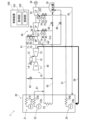
- FIG. 1 shows an example of a system diagram when the system according to the first embodiment of the present disclosure is applied to a gas turbine combined cycle power plant (GTCC).
- a system 1 shown in FIG. 1 includes a gas turbine 10 , a heat recovery boiler 20 , a steam turbine 30 , a generator 34 , a condenser 35 and a controller 100 .
- the steam turbine 30 comprises a high pressure steam turbine 31 , an intermediate pressure steam turbine 32 and a low pressure steam turbine 33 and a rotating shaft 36 of each turbine 31 , 32 and 33 .
- the generator 34 is driven by each turbine 10, 31, 32 and 33 to generate electricity.
- the condenser 35 converts the steam exhausted from the low pressure steam turbine 33 and the like back to water.
- the gas turbine 10 includes a compressor 11 , a combustor 12 , a turbine 13 , a fuel flow control valve 14 and a rotating shaft 15 .
- the compressor 11 compresses outside air to generate compressed air.
- the combustor 12 mixes and combusts the fuel gas with compressed air to generate high-temperature combustion gas.
- Turbine 13 is driven by the combustion gases.
- a fuel flow rate control valve 14 regulates the flow rate of fuel supplied to the combustor 12 .
- a rotating shaft 15 is a rotating shaft of the compressor 11 and the turbine 13 .
- a fuel line is connected to combustor 12 to supply fuel from a fuel supply to combustor 12 .
- a fuel flow control valve 14 is provided in this fuel line.
- An exhaust port of the turbine 13 is connected to the heat recovery boiler 20 by an exhaust line 56 .
- the exhaust heat recovery boiler 20 includes a high-pressure steam generator 21 , an intermediate-pressure steam generator 22 , a reheater 23 , and a low-pressure steam generator 24 .
- the exhaust heat recovery boiler 20 generates steam with the heat of the exhaust gas discharged from the gas turbine 10 .
- the high-pressure steam generator 21 includes a drum 21 a and a heat exchanger 21 b and generates high-pressure steam to be supplied to the high-pressure steam turbine 31 .
- the intermediate pressure steam generator 22 includes a drum 22 a and a heat exchanger 22 b and generates intermediate pressure steam to be supplied to the intermediate pressure steam turbine 32 .
- the reheating unit 23 heats the steam exhausted from the medium pressure steam generating unit 22 and the like.
- the low-pressure steam generator 24 includes a drum 24 a and a heat exchanger 24 b and generates low-pressure steam to be supplied to the low-pressure steam turbine 33 .
- the high-pressure steam generator 21 and the steam inlet 311 of the high-pressure steam turbine 31 are connected by a high-pressure main steam line 41 that guides the high-pressure steam to the high-pressure steam turbine 31 via a high-pressure steam stop valve 42 and a high-pressure main steam control valve 43. ing.
- the high pressure main steam line 41 is connected to the intermediate pressure main steam line 62 via a high pressure steam turbine bypass valve 63 .
- a steam outlet of the high pressure steam turbine 31 is connected to the intermediate pressure main steam line 44 via a check valve 64 and to the condenser 35 via a ventilator valve 66 .
- the medium-pressure main steam line 44 joins the medium-pressure main steam line 61 from the medium-pressure steam generating section 22 on the steam inlet side of the reheating section 23 .
- the steam outlet side of the reheating section 23 is connected to the steam inlet 321 of the intermediate pressure steam turbine 32 by the intermediate pressure main steam line 62 via the intermediate pressure steam stop valve 45 and the intermediate pressure main steam control valve 46 .
- the intermediate pressure main steam line 62 is connected to the condenser 35 via an intermediate pressure steam turbine bypass valve 65 .
- a steam inlet 331 of the low-pressure steam turbine 33 is connected to a steam outlet of the intermediate-pressure steam turbine 32 by an intermediate-pressure turbine exhaust line 54, and through a low-pressure steam stop valve 52 and a low-pressure main steam control valve 53, low-pressure steam is generated. 24 and a low-pressure main steam line 51 that guides low-pressure steam to the low-pressure steam turbine 33 .
- a steam outlet of the low-pressure steam turbine 33 is connected to a condenser 35 .
- a water supply line 55 is connected to the condenser 35 to guide the condensed water to the heat recovery boiler 20 .
- the high-pressure main steam control valve 43 adjusts the amount of steam flowing into the high-pressure steam turbine 31 under the control of the control device 100 .
- the intermediate-pressure main steam control valve 46 adjusts the amount of steam flowing into the intermediate-pressure steam turbine 32 under the control of the control device 100 .
- the low-pressure main steam control valve 53 adjusts the amount of steam flowing into the low-pressure steam turbine 33 under the control of the control device 100 . Further, the high-pressure main steam control valve 43, the intermediate-pressure main steam control valve 46, and the low-pressure main steam control valve 53 are controlled according to the valve opening command value sent from the control device 100 (hereinafter referred to as the valve opening command value). Based on this, the valve opening degree is adjusted.
- a pressure gauge 71 for measuring the high pressure main steam is provided on the upstream side of the high pressure main steam control valve 43 .
- a pressure gauge 72 for measuring the pressure-reduced high-pressure steam is provided downstream of the high-pressure main steam control valve 43 .
- the pressure gauge 72 measures the pressure value of the high-pressure steam on the steam inlet 311 side when viewed from the high-pressure main steam control valve 43 .
- a pressure gauge 73 for measuring the intermediate pressure main steam is provided on the upstream side of the intermediate pressure main steam control valve 46 .
- a pressure gauge 74 for measuring the pressure-reduced intermediate-pressure steam is provided downstream of the intermediate-pressure main steam control valve 46 .
- the pressure gauge 74 measures the pressure value of the medium-pressure steam on the steam inlet 321 side when viewed from the medium-pressure main steam control valve 46 .
- a pressure gauge 75 for measuring the low-pressure main steam is provided upstream of the low-pressure main steam control valve 53 .
- a pressure gauge 76 for measuring the pressure-reduced low-pressure steam is provided downstream of the low-pressure main steam control valve 53 .
- the pressure gauge 76 measures the pressure value of the low-pressure steam on the steam inlet 331 side when viewed from the low-pressure main steam control valve 53 .
- the pressure value of the high-pressure steam on the steam inlet 311 side measured by the pressure gauge 72 is also referred to as the HPST inlet pressure.
- the pressure value of the intermediate-pressure steam on the steam inlet 321 side measured by the pressure gauge 74 is also referred to as an IPST inlet pressure.
- the high-pressure main steam control valve 43 is also called HPCV.
- the medium-pressure main steam control valve 46 is also called IPCV.
- the high-pressure main steam control valve 43 and the intermediate-pressure main steam control valve 46 are also referred to as HP governor valves and IP governor valves.
- HPST is an abbreviation for high pressure steam turbine.
- HPST is an abbreviation for high pressure steam turbine.
- HPCV is an abbreviation for high pressure steam control valve.
- IPCV is an abbreviation for medium pressure steam control valve.
- the system 1 includes a plurality of sensors (not shown) that measure the temperature, pressure, flow rate, number of rotations (rotational speed), etc. of each part.
- the control device 100 is composed of a computer and peripheral devices of the computer, etc.
- the control device 100 is a functional configuration composed of a combination of hardware such as a computer and software such as a program executed by the computer.
- a unit 102 is provided.
- Acquisition unit 101 acquires measured values of various sensors such as pressure gauges 71-76.
- the control unit 102 controls each unit of the system 1 according to the acquisition result of the acquisition unit 101 and the like. In this embodiment, the control unit 102 adjusts the valve opening degrees of the HPCV and IPCV according to, for example, the HPST inlet pressure and the IPST inlet pressure.
- control unit 102 receives various operation data, instruction data, etc., controls the output of the gas turbine 10, controls the opening and closing of the high-pressure steam stop valve 42, controls the opening degree of the high-pressure main steam control valve 43, Steam turbine by controlling the opening and closing of the high-pressure steam stop valve 45, controlling the opening of the intermediate-pressure main steam control valve 46, controlling the opening and closing of the low-pressure steam stop valve 52, controlling the opening of the low-pressure main steam control valve 53, etc. Electric power is generated by the generator 34 by controlling the output of the generator 30 or the like. In addition, when load shedding occurs due to some abnormality or the like, the control device 100 performs various controls at the time of load shedding.
- the GTCC converts feed water in drums 21 a , 22 a and 24 a into steam using the thermal energy of the exhaust gas from the gas turbine 10 and passes the steam through the steam turbine 30 to generate power.
- the steam turbine 30 is composed of a high pressure (HP) turbine 31, an intermediate pressure (IP) turbine 32 and a low pressure (LP) turbine 33. Especially, if the received pressures of the high pressure turbine 31 and the intermediate pressure turbine 32 are not balanced, the high pressure side Alternatively, the thrust is pressed against the medium pressure side, and in the worst case, the thrust burns out, requiring huge costs for replacement.
- a sharp deviation between the HPST inlet pressure and the IPST inlet pressure is caused, for example, by the closing operation of the ventilator valve 66 when the steam turbine 30 is started or the abnormal opening operation of the high pressure steam turbine bypass valve 63 or the intermediate pressure steam turbine bypass valve 65 .
- the control device 100 monitors, for example, the main steam pressure (for example, the pressure on the upstream side of the high-pressure main steam control valve 43), and performs pressure control so as to achieve a target steam pressure determined from the load of the gas turbine 10, etc. .
- the high-pressure main steam control valve 43 is opened to lower the main steam pressure.
- the steam exhausted from the steam outlet of the high pressure steam turbine 31 reaches the steam inlet 321 through the intermediate pressure main steam lines 44 and 64 .
- the IPST inlet pressure increases, resulting in thrust unbalance.
- the control device 100 changes the upper limit value of the valve opening command value so that the balance between the HPST inlet pressure and the IPST inlet pressure is within the allowable range. Adjust valve opening.
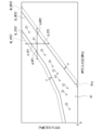
- FIG. 2 shows an outline of control according to the HPST inlet pressure and the IPST inlet pressure by the control device 100 .
- the horizontal axis represents the HPST inlet pressure
- the vertical axis represents the IPST inlet pressure.
- the white area A1 is the desired operating area
- the shaded areas A2 and A3 are thrust unbalance areas.
- the IPST inlet pressure is excessive in the upper region A2 of FIG. 2, and the HPST inlet pressure is excessive in the lower region A3.
- the control device 100 responds to the upper IPST inlet pressure excessive area A2 by reducing the IPCV, and controls the HPST excessive pressure area A3 on the lower side by reducing the HPCV to achieve the target operation balance (balance characteristic in the figure). as).
- the region A1 shown in FIG. 2 indicates the correspondence relationship between the HPST inlet pressure and the IPST inlet pressure based on the equilibrium characteristic, which is the correspondence relationship between the HPST inlet pressure and the IPST inlet pressure at which the thrust force applied to the rotating shaft 36 is appropriate.
- Range In this case, the area A1 (range) is represented by orthogonal coordinates with the horizontal axis representing the HPST inlet pressure and the vertical axis representing the IPST inlet pressure. This is an area sandwiched by B_HPST.
- the control device 100 adjusts the valve opening degrees of the HPCV and the IPCV according to the HPST inlet pressure and the IPST inlet pressure, using this area A1 (range) as a reference. At this time, control device 100 adjusts the valve opening of IPCV with reference to the upper boundary line B_IPST side of area A1, and adjusts the valve opening of HPCV with reference to the lower boundary line B_HPST side.
- the characteristics and regions shown in FIG. 2 may be expressed with the IPST inlet pressure on the horizontal axis and the HPST inlet pressure on the vertical axis. In that case, the upper boundary line and the lower boundary line will be interchanged.
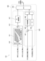
- FIG. 3 shows a configuration example of the calculation unit 200 that calculates the HPCV valve opening command value.
- FIG. 4 shows a configuration example of a calculation unit 400 that calculates the IPCV valve opening command value.
- Control unit 102 shown in FIG. 1 includes calculation unit 200 shown in FIG. 3 and calculation unit 400 shown in FIG.
- the calculation unit 200 shown in FIG. 3 includes a valve opening upper limit calculation unit 210 , a valve opening calculation unit 220 and a minimum value selector 230 .
- the valve opening calculator 220 includes a subtractor 221 , a PI controller (proportional-integral controller) 222 , and a maximum value selector 224 .
- the subtractor 221 calculates the deviation of the HP main steam pressure from the target value by subtracting the high pressure main steam pressure (HP main steam pressure) from the high pressure main steam target pressure (HP main steam target pressure).
- the PI controller 222 receives the deviation calculated by the subtractor 221 and calculates the valve opening command value of the HPCV by PI action (proportional integral action).
- the range of the valve opening command value is 0-100.
- the maximum value selector 224 outputs the larger value between "0" 223 and the calculated value of the PI controller 222 .
- the maximum value selector 224 outputs the calculated value of the PI controller 222 when the calculated value of the PI controller 222 is 0 or more.
- the HP main steam target pressure is determined, for example, from the load of the gas turbine 10, etc., as described above.
- the HP main steam pressure is the upstream pressure of the high-pressure main steam control valve 43 measured by the pressure gauge 71 .
- the valve opening calculation unit 220 adjusts the HPCV valve opening command value by feedback control so that the difference between the HP main steam target pressure and the HP main steam pressure is eliminated.
- the control element is not limited to the PI action, and may be a PID action (proportional-integral-derivative action) or may be replaced with a control element using a model such as a machine learning model.
- the valve opening upper limit value calculator 210 includes an HPST inlet pressure threshold calculator 211 , a subtractor 212 , and a PI controller 213 .
- the valve opening upper limit calculation unit 210 calculates the upper limit of the HPCV valve opening.
- the valve opening upper limit value calculated by the valve opening upper limit value calculating unit 210 and the HPCV valve opening command value calculated by the valve opening calculating unit 220 are input to the minimum value selector 230, and the smaller value is output. Therefore, the HPCV valve opening command value output by the calculation unit 200 is limited by the valve opening upper limit value calculated by the valve opening upper limit value calculation unit 210 .
- the HPST inlet pressure threshold calculation unit 211 uses the boundary line B_HPST, which is a reference for adjusting the valve opening of the HPCV described with reference to FIG. to calculate the HPST inlet pressure threshold.
- the HPST inlet pressure threshold serves as a reference for determining whether to start adjusting the upper limit (PI control), and also serves as a target value for the HPST input pressure when adjusting the upper limit. For example, as shown in FIG. 5, if the IPST inlet pressure is PL1, the HPST inlet pressure threshold calculator 211 calculates the HPST inlet pressure corresponding to the intersection C10 with the boundary line B_HPST as the HPST inlet pressure threshold.
- the subtractor 212 calculates the deviation of the HPST inlet pressure from the HPST inlet pressure threshold by subtracting the HPST inlet pressure from the HPST inlet pressure threshold.
- the PI controller 213 receives the deviation calculated by the subtractor 212 and calculates the upper limit of the valve opening of the HPCV by PI action (proportional integral action).
- PI action proportional integral action
- the control element is not limited to the PI action, and may be a PID action (proportional-integral-derivative action) or may be replaced with a control element using a model such as a machine learning model.
- the minimum value selector 230 inputs the valve opening upper limit value calculated by the valve opening upper limit value calculating unit 210 and the HPCV valve opening command value calculated by the valve opening calculating unit 220. , outputs the smaller value.
- Calculation unit 400 shown in FIG. 4 includes valve opening upper limit value calculation unit 410 , valve opening degree calculation unit 420 , and minimum value selector 430 .
- the valve opening calculator 420 includes a subtractor 421 , a PI controller (proportional integral controller) 422 and a maximum value selector 424 .
- the subtractor 421 calculates the deviation of the IP main steam pressure from the target value by subtracting the intermediate main steam pressure (IP main steam pressure) from the intermediate pressure main steam target pressure (IP main steam target pressure).
- the PI controller 422 receives the deviation calculated by the subtractor 421 and calculates the valve opening command value of the IPCV by PI operation.
- the range of the valve opening command value is 0-100.
- the maximum value selector 424 outputs the larger one of “0” 423 and the calculated value of the PI controller 422 .
- Maximum value selector 424 outputs the calculated value of PI controller 422 when the calculated value of PI controller 422 is greater than or equal to zero.
- the IP main steam target pressure is determined, for example, from the load of the gas turbine 10 or the like.
- the IP main steam pressure is the upstream pressure of the intermediate pressure main steam control valve 46 measured by the pressure gauge 73 .
- Valve-opening calculator 420 adjusts the IPCV valve-opening command value by feedback control so that the deviation between the IP main steam target pressure and the IP main steam pressure is eliminated.
- the control element is not limited to the PI operation, and may be replaced by a PID operation or a control element using a model such as a machine learning model.
- the valve opening upper limit value calculator 410 includes an IPST inlet pressure threshold value calculator 411 , a subtractor 412 , and a PI controller 413 .
- the valve opening upper limit calculation unit 410 calculates the upper limit of the IPCV valve opening.
- the valve opening upper limit value calculated by the valve opening upper limit value calculating unit 410 and the IPCV valve opening command value calculated by the valve opening calculating unit 420 are input to the minimum value selector 430, and the smaller value is output. Therefore, the IPCV valve opening command value output by the calculation unit 400 is limited by the valve opening upper limit value calculated by the valve opening upper limit calculation unit 410 .
- the IPST inlet pressure threshold calculation unit 411 uses the boundary line B_IPST, which is a reference for adjusting the valve opening of the IPCV described with reference to FIG. to calculate the IPST inlet pressure threshold.
- the IPST inlet pressure threshold serves as a reference for determining whether to start adjusting the upper limit (PI control), and also serves as a target value for the IPST input pressure when adjusting the upper limit. For example, as shown in FIG. 6, if the HPST inlet pressure is PH1, the IPST inlet pressure threshold calculator 411 calculates the IPST inlet pressure corresponding to the intersection C20 with the boundary line B_IPST as the IPST inlet pressure threshold.
- the subtractor 412 calculates the deviation of the IPST inlet pressure from the IPST inlet pressure threshold by subtracting the IPST inlet pressure from the IPST inlet pressure threshold.
- the PI controller 413 receives the deviation calculated by the subtractor 412 and calculates the upper limit value of the valve opening of the IPCV by PI action (proportional integral action).
- the control element is not limited to the PI action, and may be a PID action (proportional-integral-derivative action) or may be replaced with a control element using a model such as a machine learning model.
- the minimum value selector 430 inputs the valve opening upper limit value calculated by the valve opening upper limit value calculating unit 410 and the IPCV valve opening command value calculated by the valve opening calculating unit 420. , outputs the smaller value.
- the HPCV valve opening degree and the IPCV valve opening degree are adjusted so that the correspondence relationship between the HPST inlet pressure and the IPST inlet pressure is appropriate. Therefore, the thrust force due to the imbalance between the HPST inlet pressure and the IPST inlet pressure in the steam turbine 30 can be controlled within an allowable value.
- the pressure in the system rises (or Even if an event occurs in which the thrust balance is unbalanced due to lowering), the operation of the ST can be continued with a normal thrust balance.
- FIG. 7 is a schematic diagram for explaining an operation example of the control device according to the second embodiment of the present disclosure.
- FIG. 8 is a flow chart showing an operation example of the control device according to the second embodiment of the present disclosure.
- the configuration of the system 1 according to the second embodiment is basically the same as the configuration of the system 1 according to the first embodiment. However, in the second embodiment, the operation of the control unit 102 included in the control device 100 shown in FIG. 1 is partially different from that in the first embodiment.
- control unit 102 of the control device 100 of the second embodiment selects one of three different modes (1) during normal control, (2) during post pressure control standby, and (3) during post pressure control. Adjust the upper limit of the opening and the upper limit of the IPCV valve opening.
- FIG. 7 shows an example of temporal changes in the upper limit value of the HPCV opening command value, the HPCV opening command value, and the HPST inlet pressure when the gas turbine 10 is started. In the example shown in FIG. 7, the mode changes in the order of (1) normal control, (2) post pressure control standby, and (3) post pressure control after startup.
- the post-pressure control is control for adjusting the upper limit value by the HPST inlet pressure, which is the pressure on the downstream side of the HPCV, and is the same as the control of the upper limit value in the first embodiment.
- the control based on the pressure on the downstream side of the HPCV is referred to as post pressure control.
- the control of the upper limit value of the IPCV opening command value is the same as the control of the upper limit value of the HPCV opening command value, and the control of the upper limit value of the HPCV opening command value will be described below as an example.
- normal control is executed from time t0 to t1.
- the HPST input pressure becomes equal to or higher than the HPST input pressure threshold value (not shown), and the post pressure control standby time is reached.
- the HPST input pressure becomes equal to or higher than the HPST target pressure, and post pressure control is executed.
- the upper limit of the HPCV valve opening command value indicated by the two-dot chain line is the maximum opening constant. Further, during normal control, the HPCV valve opening command value is set toward the HPST target pressure indicated by the one-dot chain line, and the HPST input pressure increases. During post pressure control standby, the upper limit of the HPCV valve opening command value is set to the current valve opening + ⁇ 1%. Then, during post pressure control, PI control with an upper limit value is started, and the HPCV valve opening degree is suppressed at the upper limit value. Note that the HPCV valve opening degree in the case of front pressure control without back pressure control continues to increase, for example, as indicated by the dashed line.
- the front pressure control is control based on the pressure on the upstream side of the HPCV.
- HPCV is written as HP governor valve
- IPCV is written as IP governor valve.
- the control unit 102 of the second embodiment adjusts the valve opening degree of the HPCV (HP governor valve) by the processing of steps S11 to S18, and adjusts the valve opening degree of the IPCV (IP governor valve) by the processing of steps S21 to S28. and are executed in parallel.
- the control unit 102 calculates the HPST inlet pressure threshold value based on the IPST inlet pressure with reference to the boundary line B_HPST in the correspondence relationship between the HPST input pressure and the IPST input pressure shown in FIG. 5 (step S11). Note that the process of step S11 is executed at predetermined time intervals.
- the control unit 102 determines whether or not the HPST inlet pressure is equal to or higher than the HPST inlet pressure threshold (step S12). If the HPST inlet pressure is not equal to or higher than the HPST inlet pressure threshold value (step S12: NO), the control unit 102 executes HP governor valve normal control with the valve opening upper limit as the maximum value (step S13), and returns to step S11. .
- step S12 If the HPST inlet pressure is equal to or higher than the HPST inlet pressure threshold (step S12: YES), the control unit 102 sets the valve opening upper limit value to the current opening + ⁇ 1, and shifts to the HP governor valve post-pressure control standby state (Ste S14), it is determined whether or not the HPST inlet pressure is equal to or higher than the target pressure (step S15).
- step S15: NO When the HPST inlet pressure is not equal to or higher than the target pressure (step S15: NO), the control section 102 returns the process to step S11. If the HPST inlet pressure is equal to or higher than the target pressure (step S15: YES), the control unit 102 executes HP governor valve post pressure control (step S16), and checks whether the HPST inlet pressure is less than the HPST inlet pressure threshold value. Determine (step S17). If the HPST inlet pressure is not less than the HPST inlet pressure threshold (step S17: NO), the control unit 102 calculates the HPST inlet pressure threshold (step S18), and after a predetermined time, executes the process of step S16. If the HPST inlet pressure is less than the HPST inlet pressure threshold (step S17: YES), the control unit 102 returns the process to step S11.
- step S21 the control unit 102 calculates the IPST inlet pressure based on the HPST inlet pressure with reference to the boundary line B_IPST in the correspondence relationship between the HPST input pressure and the IPST input pressure shown in FIG. A threshold is calculated (step S21). Note that the process of step S21 is executed at predetermined time intervals.
- the control unit 102 determines whether or not the IPST inlet pressure is greater than or equal to the IPST inlet pressure threshold (step S22). If the IPST inlet pressure is not equal to or greater than the IPST inlet pressure threshold value (step S22: NO), the control unit 102 performs IP governor valve normal control with the valve opening upper limit as the maximum value (step S23), and returns to step S21.
- step S22 If the IPST inlet pressure is equal to or higher than the IPST inlet pressure threshold value (step S22: YES), the control unit 102 sets the valve opening upper limit value to the current opening + ⁇ 2, and shifts to the IP governor valve post-pressure control standby state (Ste S24), it is determined whether or not the IPST inlet pressure is equal to or higher than the target pressure (step S25).
- ⁇ 2 is a constant value on the IPST inlet pressure side corresponding to ⁇ 1.
- step S25: NO If the IPST inlet pressure is not equal to or higher than the target pressure (step S25: NO), the control unit 102 returns the process to step S21. If the IPST inlet pressure is equal to or higher than the target pressure (step S25: YES), the control unit 102 executes IP governor valve post pressure control (step S26), and determines whether the IPST inlet pressure is less than the IPST inlet pressure threshold value. Determine (step S27). If the IPST inlet pressure is not less than the IPST inlet pressure threshold (step S27: NO), the control unit 102 calculates the IPST inlet pressure threshold (step S28), and after a predetermined time, executes the process of step S26. If the IPST inlet pressure is less than the IPST inlet pressure threshold (step S27: YES), the control unit 102 returns the process to step S21.
- the HPCV valve opening degree and the IPCV valve opening degree are adjusted so that the correspondence relationship between the HPST inlet pressure and the IPST inlet pressure is appropriate. Therefore, the thrust force due to the imbalance between the HPST inlet pressure and the IPST inlet pressure in the steam turbine 30 can be controlled within an allowable value.
- control unit 102 selectively sets the upper limit values of the HPCV valve opening degree and the IPCV valve opening degree to the maximum value of each valve opening degree, the HPST inlet pressure, and the IPST inlet pressure. or each value based on the area A1, the upper limit of the valve opening of the HPCV and the valve opening of the IPCV Adjust the upper limit. With this configuration, the valve can be quickly closed when the HPST inlet pressure or IPST inlet pressure is about to deviate from the allowable range.
- FIG. 9 is a schematic diagram for explaining a control device according to a third embodiment of the present disclosure.
- the third embodiment presents the procedure for determining the thrust balance target range (area A1 in FIG. 2) shown in the first embodiment.
- the area A1 (range) is determined by the following procedure.
- an area A1a sandwiched between the boundary line M_HPST and the boundary line M_IPST indicated by the dashed line is determined so as not to exceed the range in which the HPST inlet pressure is biased and the range in which the IPST inlet pressure is biased at each point C1.
- a boundary line B_HPST and a boundary line B_IPST of the area A1 are obtained by subtracting a constant ⁇ (adjustment term) from the boundary line M_HPST and the boundary line M_IPST between the HPST inlet pressure and the IPST inlet pressure obtained in (S2).
- the region A1 (range) described with reference to FIG. This corresponds to a region A1a in which the thrust force is equal to or less than the maximum allowable value when one of the HPST inlet pressure and the IPST inlet pressure is biased.
- the control unit 102 controls the HPCV valve opening and It adjusts the valve opening of the IPCV.
- FIG. 10 is a schematic block diagram showing the configuration of a computer according to at least one embodiment;
- Computer 90 comprises processor 91 , main memory 92 , storage 93 and interface 94 .
- the control device 100 described above is implemented in the computer 90 .
- the operation of each processing unit described above is stored in the storage 93 in the form of a program.
- the processor 91 reads out the program from the storage 93, develops it in the main memory 92, and executes the above processes according to the program.
- the processor 91 secures storage areas corresponding to the storage units described above in the main memory 92 according to the program.
- the program may be for realizing part of the functions to be exhibited by the computer 90.
- the program may function in combination with another program already stored in the storage or in combination with another program installed in another device.
- the computer may include a custom LSI (Large Scale Integrated Circuit) such as a PLD (Programmable Logic Device) in addition to or instead of the above configuration.
- PLD Programmable Logic Device
- Examples of PLD include PAL (Programmable Array Logic), GAL (Generic Array Logic), CPLD (Complex Programmable Logic Device), FPGA (Field Programmable Gate Array), and the like.
- part or all of the functions implemented by the processor may be implemented by the integrated circuit.
- Examples of the storage 93 include HDD (Hard Disk Drive), SSD (Solid State Drive), magnetic disk, magneto-optical disk, CD-ROM (Compact Disc Read Only Memory), DVD-ROM (Digital Versatile Disc Read Only Memory) , semiconductor memory, and the like.
- the storage 93 may be an internal medium directly connected to the bus of the computer 90, or an external medium connected to the computer 90 via an interface 94 or communication line. Further, when this program is distributed to the computer 90 via a communication line, the computer 90 receiving the distribution may develop the program in the main memory 92 and execute the above process.
- storage 93 is a non-transitory, tangible storage medium.
- control device 100 described in each embodiment is understood as follows.
- the control device 100 uses the first steam (high-pressure steam) supplied from the first inlet (steam inlet 311) through the first control valve (high-pressure main steam control valve 43).
- the thrust force in the steam turbine can be controlled within an allowable value.
- the control device 100 of the second aspect is the control device of (1), wherein the control unit 102 controls the first inlet pressure and the second inlet pressure at which the thrust force applied to the rotating shaft 36 is appropriate.
- the first control valve is opened according to the first inlet pressure and the second inlet pressure based on a predetermined range (region A1) of the correspondence relationship based on the correspondence relationship (equilibrium characteristic) of the inlet pressures. and the valve opening degree of the second control valve.
- the valve opening degree of the first control valve and the valve opening degree of the second control valve can be adjusted so that the correspondence relationship between the first inlet pressure and the second inlet pressure is appropriate.
- the thrust force due to the imbalance between the first inlet pressure and the second inlet pressure in the steam turbine 30 can be controlled within an allowable value.
- the control device 100 of the third aspect is the control device 100 of (2), wherein the control unit 102 defines the range (region A1) with the horizontal axis representing the first inlet pressure and the second pressure
- the control unit 102 defines the range (region A1) with the horizontal axis representing the first inlet pressure and the second pressure
- the upper boundary line (B_IPST) side of the range is used as a reference for the first control valve and one of the second control valves
- the other of the first control valve and the second control valve is adjusted based on the lower boundary line (B_HPST) of the range.
- the control device 100 of the fourth aspect is the control device 100 of (2) or (3), wherein the range (region A1) is the thrust force from the first turbine and the thrust force from the second turbine.
- the thrust force when one of the first inlet pressure and the second inlet pressure is deviated from the combination (C1) of the first inlet pressure and the second inlet pressure that balance forces is equal to or less than the maximum allowable value. It corresponds to a certain area A1a.
- the control device 100 of the fifth aspect is the control device 100 of (4), wherein the control unit 102 moves a region obtained by subtracting a predetermined constant ⁇ from the boundary of the region A1a to the inside of the region A1a.
- A1 as the range (area A1)
- the valve opening degrees of the first control valve and the valve opening degrees of the second control valve are adjusted according to the first inlet pressure and the second inlet pressure.
- the control device 100 of the sixth aspect is the control device 100 of (2) to (5), wherein the control unit 102 controls the upper limit value of the opening degree of the first control valve and the second control valve.
- the control unit 102 controls the upper limit value of the opening degree of the first control valve and the second control valve.
- the valve opening of the first control valve and the valve opening of the second control valve are controlled according to the first inlet pressure and the second inlet pressure.
- adjust the According to this aspect for example, feedback control of the upstream pressure of the first control valve by the first control valve, feedback control of the upstream pressure of the second control valve by the second control valve, etc. can be easily combined. can be done.
- the control device 100 of the seventh aspect is the control device 100 of (6), wherein the control unit 102 controls the valve opening degree of the first control valve and the valve opening degree of the second control valve.
- Each upper limit value is selectively increased by a predetermined amount ( ⁇ 1, ⁇ 2) from the maximum value of each valve opening, each current value of each of the first inlet pressure and the second inlet pressure, or the above
- the upper limit value of the valve opening degree of the first control valve and the upper limit value of the valve opening degree of the second control valve are adjusted by setting one of the values based on the range (region A1). According to this aspect, it is possible to improve the responsiveness of the control based on the upper limit value.
- the thrust force in the steam turbine can be controlled within an allowable value.
Abstract
Le présent dispositif de commande comprend : une unité d'acquisition destinée à acquérir, en tant que première pression d'entrée, une valeur de pression de la première vapeur sur un premier côté d'entrée, vue à partir d'une première vanne de régulation d'une première turbine qui tourne à l'aide de la première vapeur, qui est alimentée à partir de la première entrée par l'intermédiaire de la première vanne de régulation et à acquérir, en tant que seconde pression d'entrée, une valeur de pression de la seconde vapeur sur un second côté d'entrée, vue à partir d'une seconde vanne de régulation d'une seconde turbine qui tourne sur le même arbre rotatif que la première turbine à l'aide de la seconde vapeur, qui est fournie à partir de la seconde entrée par l'intermédiaire de la seconde vanne de régulation ; et une unité de commande destinée à réguler un degré d'ouverture de la première vanne de régulation et un degré d'ouverture de la seconde vanne de régulation en fonction de la première pression d'entrée et de la seconde pression d'entrée.
Priority Applications (1)
| Application Number | Priority Date | Filing Date | Title |
|---|---|---|---|
| JP2023564755A JPWO2023100457A1 (fr) | 2021-11-30 | 2022-09-27 |
Applications Claiming Priority (2)
| Application Number | Priority Date | Filing Date | Title |
|---|---|---|---|
| JP2021-194470 | 2021-11-30 | ||
| JP2021194470 | 2021-11-30 |
Publications (1)
| Publication Number | Publication Date |
|---|---|
| WO2023100457A1 true WO2023100457A1 (fr) | 2023-06-08 |
Family
ID=86611828
Family Applications (1)
| Application Number | Title | Priority Date | Filing Date |
|---|---|---|---|
| PCT/JP2022/035945 WO2023100457A1 (fr) | 2021-11-30 | 2022-09-27 | Dispositif de commande, procédé de commande et système |
Country Status (2)
| Country | Link |
|---|---|
| JP (1) | JPWO2023100457A1 (fr) |
| WO (1) | WO2023100457A1 (fr) |
Citations (6)
| Publication number | Priority date | Publication date | Assignee | Title |
|---|---|---|---|---|
| JPS6040703A (ja) * | 1983-08-12 | 1985-03-04 | Hitachi Ltd | タ−ビンのスラスト力調整装置 |
| JP2008008291A (ja) * | 2006-06-29 | 2008-01-17 | General Electric Co <Ge> | タービンの望ましくない運転を検出するためのシステム及び方法 |
| JP2012007610A (ja) * | 2010-06-23 | 2012-01-12 | General Electric Co <Ge> | 蒸気タービンにおけるスラスト制御システム |
| JP2014202136A (ja) * | 2013-04-05 | 2014-10-27 | 富士電機株式会社 | 抽気蒸気タービン発電設備の保安運転方法および装置 |
| JP2018091224A (ja) * | 2016-12-02 | 2018-06-14 | 三菱日立パワーシステムズ株式会社 | 制御システム、蒸気タービン、発電プラント及び制御方法 |
| WO2018167907A1 (fr) * | 2017-03-16 | 2018-09-20 | 三菱重工コンプレッサ株式会社 | Turbine à vapeur |
-
2022
- 2022-09-27 JP JP2023564755A patent/JPWO2023100457A1/ja active Pending
- 2022-09-27 WO PCT/JP2022/035945 patent/WO2023100457A1/fr active Application Filing
Patent Citations (6)
| Publication number | Priority date | Publication date | Assignee | Title |
|---|---|---|---|---|
| JPS6040703A (ja) * | 1983-08-12 | 1985-03-04 | Hitachi Ltd | タ−ビンのスラスト力調整装置 |
| JP2008008291A (ja) * | 2006-06-29 | 2008-01-17 | General Electric Co <Ge> | タービンの望ましくない運転を検出するためのシステム及び方法 |
| JP2012007610A (ja) * | 2010-06-23 | 2012-01-12 | General Electric Co <Ge> | 蒸気タービンにおけるスラスト制御システム |
| JP2014202136A (ja) * | 2013-04-05 | 2014-10-27 | 富士電機株式会社 | 抽気蒸気タービン発電設備の保安運転方法および装置 |
| JP2018091224A (ja) * | 2016-12-02 | 2018-06-14 | 三菱日立パワーシステムズ株式会社 | 制御システム、蒸気タービン、発電プラント及び制御方法 |
| WO2018167907A1 (fr) * | 2017-03-16 | 2018-09-20 | 三菱重工コンプレッサ株式会社 | Turbine à vapeur |
Also Published As
| Publication number | Publication date |
|---|---|
| JPWO2023100457A1 (fr) | 2023-06-08 |
Similar Documents
| Publication | Publication Date | Title |
|---|---|---|
| JPH04232311A (ja) | 複合サイクル・タ―ビンの超過速度を予想及び制限する方法と装置 | |
| KR101908200B1 (ko) | 증기 분사 기구를 갖는 2축식 가스 터빈 | |
| JP2012167571A (ja) | 一軸型複合サイクル発電プラントおよびその運転方法 | |
| US10287921B2 (en) | Combined cycle plant, method for controlling same, and device for controlling same | |
| US8857184B2 (en) | Method for starting a turbomachine | |
| JP5694112B2 (ja) | 一軸型複合サイクル発電プラント及びその運転方法 | |
| JP2016070223A (ja) | 蒸気タービン設備及び蒸気タービン設備の制御方法 | |
| WO2023100457A1 (fr) | Dispositif de commande, procédé de commande et système | |
| JP6684453B2 (ja) | 蒸気タービン発電機の抽気制御方法及びその制御装置 | |
| EP2508718B1 (fr) | Procédé d'arrêt d'une turbomachine | |
| US20210033025A1 (en) | Plant control apparatus, plant control method and power plant | |
| JP6781613B2 (ja) | 制御システム、蒸気タービン、発電プラント及び制御方法 | |
| JP2003106170A (ja) | ガスタービンおよびガスタービン複合プラント、並びに冷却蒸気圧力調整方法 | |
| US20120151918A1 (en) | Method for operating a turbomachine during a loading process | |
| JP2003254011A (ja) | 多軸型コンバインドサイクル発電プラントの運転方法 | |
| JPH0337304A (ja) | タービンバイパス装置を備えた蒸気タービン発電プラントの起動方法 | |
| US11619145B2 (en) | Coordinated combined cycle power plant response for block loading in grid restoration | |
| JP2999122B2 (ja) | 複合プラントの制御装置 | |
| JP2019522752A (ja) | タービン加減弁の動的相互作用 | |
| JP5781915B2 (ja) | コンバインドプラントとその制御方法 | |
| JP3784947B2 (ja) | タービン速度制御方法 | |
| JP5627409B2 (ja) | コンバインドサイクル発電プラントおよび制御装置 | |
| JPS6154927B2 (fr) | ||
| JPS6246681B2 (fr) | ||
| JPS63143305A (ja) | タ−ビン過負荷防止方法 |
Legal Events
| Date | Code | Title | Description |
|---|---|---|---|
| 121 | Ep: the epo has been informed by wipo that ep was designated in this application |
Ref document number: 22900892 Country of ref document: EP Kind code of ref document: A1 |
|
| WWE | Wipo information: entry into national phase |
Ref document number: 2023564755 Country of ref document: JP |