WO2023100445A1 - 収容装置 - Google Patents
収容装置 Download PDFInfo
- Publication number
- WO2023100445A1 WO2023100445A1 PCT/JP2022/034472 JP2022034472W WO2023100445A1 WO 2023100445 A1 WO2023100445 A1 WO 2023100445A1 JP 2022034472 W JP2022034472 W JP 2022034472W WO 2023100445 A1 WO2023100445 A1 WO 2023100445A1
- Authority
- WO
- WIPO (PCT)
- Prior art keywords
- slot
- storage device
- mobile battery
- axis direction
- housing
- Prior art date
- Legal status (The legal status is an assumption and is not a legal conclusion. Google has not performed a legal analysis and makes no representation as to the accuracy of the status listed.)
- Ceased
Links
Images


Classifications
-
- H—ELECTRICITY
- H01—ELECTRIC ELEMENTS
- H01M—PROCESSES OR MEANS, e.g. BATTERIES, FOR THE DIRECT CONVERSION OF CHEMICAL ENERGY INTO ELECTRICAL ENERGY
- H01M10/00—Secondary cells; Manufacture thereof
- H01M10/42—Methods or arrangements for servicing or maintenance of secondary cells or secondary half-cells
- H01M10/46—Accumulators structurally combined with charging apparatus
-
- H—ELECTRICITY
- H01—ELECTRIC ELEMENTS
- H01M—PROCESSES OR MEANS, e.g. BATTERIES, FOR THE DIRECT CONVERSION OF CHEMICAL ENERGY INTO ELECTRICAL ENERGY
- H01M50/00—Constructional details or processes of manufacture of the non-active parts of electrochemical cells other than fuel cells, e.g. hybrid cells
- H01M50/20—Mountings; Secondary casings or frames; Racks, modules or packs; Suspension devices; Shock absorbers; Transport or carrying devices; Holders
- H01M50/244—Secondary casings; Racks; Suspension devices; Carrying devices; Holders characterised by their mounting method
-
- H—ELECTRICITY
- H01—ELECTRIC ELEMENTS
- H01M—PROCESSES OR MEANS, e.g. BATTERIES, FOR THE DIRECT CONVERSION OF CHEMICAL ENERGY INTO ELECTRICAL ENERGY
- H01M50/00—Constructional details or processes of manufacture of the non-active parts of electrochemical cells other than fuel cells, e.g. hybrid cells
- H01M50/20—Mountings; Secondary casings or frames; Racks, modules or packs; Suspension devices; Shock absorbers; Transport or carrying devices; Holders
- H01M50/251—Mountings; Secondary casings or frames; Racks, modules or packs; Suspension devices; Shock absorbers; Transport or carrying devices; Holders specially adapted for stationary devices, e.g. power plant buffering or backup power supplies
-
- H—ELECTRICITY
- H01—ELECTRIC ELEMENTS
- H01M—PROCESSES OR MEANS, e.g. BATTERIES, FOR THE DIRECT CONVERSION OF CHEMICAL ENERGY INTO ELECTRICAL ENERGY
- H01M50/00—Constructional details or processes of manufacture of the non-active parts of electrochemical cells other than fuel cells, e.g. hybrid cells
- H01M50/20—Mountings; Secondary casings or frames; Racks, modules or packs; Suspension devices; Shock absorbers; Transport or carrying devices; Holders
- H01M50/296—Mountings; Secondary casings or frames; Racks, modules or packs; Suspension devices; Shock absorbers; Transport or carrying devices; Holders characterised by terminals of battery packs
-
- H—ELECTRICITY
- H02—GENERATION; CONVERSION OR DISTRIBUTION OF ELECTRIC POWER
- H02J—CIRCUIT ARRANGEMENTS OR SYSTEMS FOR SUPPLYING OR DISTRIBUTING ELECTRIC POWER; SYSTEMS FOR STORING ELECTRIC ENERGY
- H02J7/00—Circuit arrangements for charging or depolarising batteries or for supplying loads from batteries
-
- H—ELECTRICITY
- H05—ELECTRIC TECHNIQUES NOT OTHERWISE PROVIDED FOR
- H05K—PRINTED CIRCUITS; CASINGS OR CONSTRUCTIONAL DETAILS OF ELECTRIC APPARATUS; MANUFACTURE OF ASSEMBLAGES OF ELECTRICAL COMPONENTS
- H05K5/00—Casings, cabinets or drawers for electric apparatus
- H05K5/02—Details
-
- Y—GENERAL TAGGING OF NEW TECHNOLOGICAL DEVELOPMENTS; GENERAL TAGGING OF CROSS-SECTIONAL TECHNOLOGIES SPANNING OVER SEVERAL SECTIONS OF THE IPC; TECHNICAL SUBJECTS COVERED BY FORMER USPC CROSS-REFERENCE ART COLLECTIONS [XRACs] AND DIGESTS
- Y02—TECHNOLOGIES OR APPLICATIONS FOR MITIGATION OR ADAPTATION AGAINST CLIMATE CHANGE
- Y02E—REDUCTION OF GREENHOUSE GAS [GHG] EMISSIONS, RELATED TO ENERGY GENERATION, TRANSMISSION OR DISTRIBUTION
- Y02E60/00—Enabling technologies; Technologies with a potential or indirect contribution to GHG emissions mitigation
- Y02E60/10—Energy storage using batteries
Definitions
- the present invention relates to an accommodation device that accommodates a power storage device in an accommodation portion.
- a holding device that houses a mobile battery.
- a mobile battery is a power storage device that stores electric power.
- the holding device charges the mobile battery.
- the holding device supplies power supplied from the mobile battery to the external load.
- This holding device has a plurality of slots (accommodating portions).
- a mobile battery can be inserted into and removed from each of the plurality of slots.
- a user inserts, for example, a mobile battery with a low state of charge (SOC) into one slot. The user pulls out another mobile battery whose SOC has become sufficiently high from another slot.
- SOC state of charge
- the slot has a member with an opening for inserting and removing the mobile battery.
- the user brings one side of the bottom of the mobile battery into contact with the member.
- the member bears part of the weight of the mobile battery.
- the user pushes the mobile battery into the slot while sliding one side of the mobile battery (the side facing vertically downward) against the member.
- the one side surface of the mobile battery comes into sliding contact with the member.
- the member may be worn and a sliding contact mark may be formed.
- the inside of the accommodating portion is stained with the abrasion powder.
- An object of the present invention is to solve the above-mentioned problems.
- a housing device including a housing section for detachably housing a power storage device having a power storage section, wherein the housing section includes an opening, a tubular section in which the opening is formed, and a bottom portion connected to the cylindrical portion, the opening, the cylindrical portion, and the bottom portion forming a bottomed cylindrical shape.
- a storage device is provided, wherein one or more protruding ridges are provided, said ridges being provided to extend along a direction from said opening toward said bottom.
- the power storage device comes into sliding contact with the inner surface of the housing portion when the power storage device is inserted into or removed from the housing portion.
- the power storage device comes into sliding contact with the ridge portion.
- a contact area between the power storage device and the ridge portion is smaller than a contact area between the power storage device and the inner surface of the housing portion. Therefore, the amount of abrasion powder generated is reduced.
- the present invention it is also possible to avoid the occurrence of traces of sliding contact of the power storage device on the inner surface of the accommodating portion. This is because, as described above, the power storage device is preferentially slidably contacted with the ridge portion, so that the power storage device is prevented from being slidably contacted with the inner surface of the housing portion.
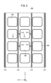
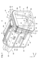
- FIG. 1 is an external schematic diagram of a storage device.
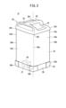
- FIG. 2 is a perspective view of a mobile battery.
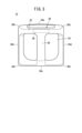
- FIG. 3 is a plan view of the mobile battery.
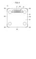
- FIG. 4 is a bottom view of the mobile battery.
- FIG. 5 is a rear view of the rear surface of the front panel.
- FIG. 6 is a sectional view taken along line VI-VI in FIG.
- FIG. 7 is a schematic overall perspective view of the slot.
- FIG. 8 is a cross-sectional side view of the slot.
- FIG. 9 is an enlarged perspective view of essential parts of the slot.
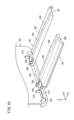
- FIG. 10 is a schematic perspective view of a first in-cylinder rail forming a second ridge portion.
- FIG. 11 is a cross-sectional view of the essential parts of the first in-cylinder rail.
- FIG. 10 is a schematic perspective view of a first in-cylinder rail forming a second ridge portion.
- FIG. 11 is a cross-sectional view of the essential parts of the first in-
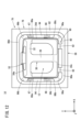
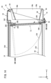
- FIG. 12 is a schematic front view of the slot.
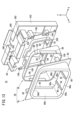
- FIG. 13 is an exploded perspective view of the bezel.
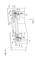
- FIG. 14 is a side cross-sectional view of the slot showing the movement trajectory of the door.
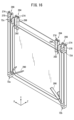
- FIG. 15 is a schematic perspective view of the essential part showing the structure of the mounting portion of the door in the slot when the door is positioned at the second position.
- FIG. 16 is a rear view of the door looking at the side facing the inside of the slot.
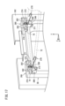
- FIG. 17 is a schematic perspective view of essential parts when the door is moved to the first position from the state of FIG. 15;
- FIG. 18 is an overall perspective view of a torsion spring that pushes the door.
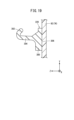
- FIG. 19 is a cross-sectional view of essential parts of the gasket.
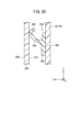
- FIG. 20 is a fragmentary cross-sectional view of a crushed gasket.
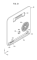
- FIG. 21 is a schematic perspective view of a bottom cover forming the bottom of the slot.
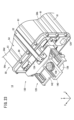
- Figure 22 is a schematic rear perspective view of the slot;
- Figure 23 is a schematic rear perspective view of the slot at another angle than Figure 22;
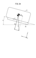
- FIG. 24 is an action diagram in which gravity acting on a mobile battery (electric device) inserted into a slot is exploded.
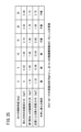
- FIG. 25 is a chart showing the relationship between the inclination angle of the slot with respect to the horizontal direction and the dynamic friction force of the first in-cylinder rail.
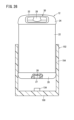
- FIG. 26 is a vertical cross-sectional view of an accommodation device according to another aspect.
- the accommodation device 10 (or holding device) shown in FIG. 1 will be exemplified and explained based on the X-axis, Y-axis and Z-axis defined as follows.
- the direction in which the mobile battery 12 is inserted into and removed from the slot 14 is defined as the Z-axis direction.
- the direction from the innermost part of the slot 14 toward the opening is defined as +Z-axis direction.
- the +Z-axis direction is the withdrawal direction in which the mobile battery 12 is removed from the slot 14 .
- the ⁇ Z-axis direction is the opposite direction to the +Z-axis direction.
- the ⁇ Z-axis direction is the direction in which the mobile battery 12 is inserted into the slot 14 . That is, the Z-axis direction is the insertion/removal direction of the mobile battery 12 .
- the direction parallel to the width direction of the accommodation device 10 is defined as the X-axis direction.
- the right hand side in the X-axis direction is the +X-axis direction.
- the ⁇ X-axis direction is the opposite direction to the +X-axis direction and is the left-hand side in the X-axis direction.
- a direction orthogonal to the Z-axis and the X-axis is defined as the Y-axis direction.
- the upper side is the +Y-axis direction.
- the lower side is the -Y-axis direction.
- the wording "insertable” is substantially synonymous with the wording "detachable”. That is, the mobile battery 12 can be attached (inserted) into the slot 14 and can be removed (pulled out) from the slot 14 .
- the term “detachable” means that the mobile battery 12 can be freely inserted into and removed from the slot 14 without the user using a tool or the like.
- the wording "insertion and removal” is synonymous with the wording "insertion and removal”. Therefore, "inserted and removed” or “attached and detached” are synonymous with “inserted and removed.”
- FIG. 1 is an external schematic view of the housing device 10.
- a mobile battery 12 power storage device
- This housing device 10 is a device that charges a mobile battery 12 housed inside the housing device 10 .
- the user pushes the mobile battery 12 with a low state of charge (SOC) into the storage device 10 .
- SOC state of charge
- the accommodation device 10 has 12 slots 14 (accommodation portions or holding portions) and one operation panel 16 .
- a mobile battery 12 is accommodated in each of the twelve slots 14 .
- the accommodation device 10 starts charging the mobile battery 12 accommodated in the slot 14 .
- the operation panel 16 is a device operated by the user. By operating the operation panel 16, the user pays a fee, for example.
- FIG. 2 is a perspective view of the mobile battery 12.
- FIG. 3 is a plan view of the mobile battery 12.
- FIG. 4 is a bottom view of the mobile battery 12.
- the mobile battery 12 has a bottom case 20, a main case 22, and a top case 24.
- the bottom case 20 , the main case 22 and the top case 24 constitute a housing for the mobile battery 12 .
- the bottom case 20 constitutes the bottom surface of the mobile battery 12 .
- the top case 24 constitutes the upper surface of the mobile battery 12.
- a handle 30 is provided on the upper surface.
- the handle 30 has a first gripping portion 28 and a second gripping portion 32 . The user grips the handle 30 and inserts/removes the mobile battery 12 into/from the slot 14 .
- the main case 22 is a square cylindrical hollow body with open ends (see FIG. 2). Therefore, mobile battery 12 has four sides.
- the four sides are side 34a, side 34b, side 34c and side 34d.
- a side surface 34a therein has an outwardly convex curved shape.
- the side surface 34 a is a surface corresponding to the second grip portion 32 .
- Sides 34b, 34c and 34d are substantially flat. Although the entire side surface 34a is curved in the illustrated example, a portion of the side surface 34a may be partially curved.
- a cell pack is accommodated in the main case 22 .
- a cell pack is configured by electrically connecting a plurality of unit cells. Since this configuration is known, for example, as described in Japanese Patent Application Laid-Open No. 2020-198229, illustration and description are omitted.
- a cell pack corresponds to the power storage unit of the present invention.
- the female connector 26 (first electrical terminal) is exposed on the bottom surface.
- the connector 26 has female electrical terminals for transmitting and receiving power and female communication terminals for transmitting and receiving communication signals. That is, the connector 26 serves as both an electrical terminal and a communication terminal.
- a connector 26 is provided in a recessed space 27 on the bottom surface. That is, the connector 26 is provided at a position slightly closer to the top case 24 from the bottom surface. The connector 26 is located from the center of the bottom surface toward the end where the second grip portion 32 is provided.
- a female connector 26 is sometimes called a receptacle.
- a light metal is selected as the material of the bottom case 20, the main case 22 and the top case 24.
- Suitable examples of light metals include aluminum or aluminum alloys. This is because aluminum or an aluminum alloy is lightweight and chemically stable.
- the storage device 10 has a housing 200 .
- the housing 200 has an apparatus main body 202 as a main part and a front panel 204 as a separate part.
- An exposure window 206 is formed as an opening in the front panel 204 .
- the number of exposed windows 206 is the same as the number of slots 14 .
- a bezel 70 that is part of the slot 14 is exposed through the exposure window 206 .
- the design surface 208 of the front panel 204 is shown.
- the design surface 208 is an arrangement surface of the outer surface of the front panel 204 that faces the user (+Z-axis direction). Therefore, the user visually recognizes the design surface 208 .
- the +Z-axis direction facing the user is the first direction.
- FIG. 5 and 6 show the back surface 210 of the front panel 204.
- FIG. A back surface 210 of the front panel 204 is a surface opposite to the design surface 208 and faces the apparatus body 202 .
- a rear surface 210 of the front panel 204 is provided with four U-shaped ribs 212 (reinforcing portions).
- the U-shaped rib 212 extends along the Y direction, which is the longitudinal direction of the front panel 204 .
- the opening of the U-shaped rib 212 faces the device body 202 .
- Two of the four U-shaped ribs 212 are provided at both ends in the X direction, which is the width direction.
- the remaining two of the four U-shaped ribs 212 are provided between two widthwise adjacent rows of exposure windows 206 .
- a plurality of (for example, four) strikers 214 are provided at a site different from the site where the U-shaped rib 212 is provided.
- the device main body 202 is provided with a latch (not shown). As the striker 214 is restrained by the latch, the front panel 204 is assembled to the device main body 202 .
- the inner peripheral edge of the exposed window 206 is burred over the entire circumference. Specifically, the inner peripheral edge of the exposure window 206 is folded back at an acute angle from the design surface 208 toward the back surface 210 facing the apparatus main body 202 . As a result, a folded portion 216 (so-called burring) is formed on the inner peripheral edge portion of the exposure window 206 . U-shaped ribs 212 and folds 216 provide front panel 204 with greater stiffness. The folded portion 216 encircles the inner peripheral edge of the exposure window 206 . In other words, the folded portion 216 is provided over the entire inner peripheral edge of the exposure window 206 .
- the folding angle of the folding portion 216 may be a right angle.
- the tip of the folded portion 216 is located on the outer periphery of the exposed window 206 . Therefore, the circumference of the tip of the folded portion 216 is longer than the circumference of the inner circumference of the exposure window 206 .
- the inner circumference of the exposure window 206 is longer than the inner circumference of the entrance/exit of the mobile battery 12 in the slot 14 .
- the entrance/exit of the slot 14 is the first insertion opening 86a shown in FIGS. 9 and 13 and the like. The first insertion opening 86a will be described later.
- the material of the front panel 204 is preferably a material that can be easily burred. Suitable examples of such materials include hard metals. A typical example of a hard metal is stainless steel.
- a gasket 220 shown in FIG. 9 is interposed between the outer surface of the slot 14 and the back surface 210 of the front panel 204 . Gasket 220 will be described later.
- FIG. 7 is a schematic overall perspective view of the slot 14.
- FIG. 7 shows a state in which the mobile battery 12 is not inserted into the slot 14.
- FIG. 8 is a cross-sectional side view of slot 14.
- FIG. 8 shows a state in which the mobile battery 12 is inserted into the slot 14.
- the slot 14 has a slot sleeve 50 and a battery lock mechanism 52.
- Slot sleeve 50 holds mobile battery 12 .
- the slot sleeve 50 has a slot body 54 , a slot flange 56 , a slot guide 58 and a bottom cover 60 .
- the slot body 54 is a tubular member (tubular portion) having a lower plate 54a, a left plate 54b, a right plate 54c, and an upper plate 54d.
- the slot body 54 extends along the Z-axis direction.
- the Z-axis direction is the insertion/removal direction of the mobile battery 12 .
- the slot body 54 is a hollow body having a substantially quadrangular prism shape. Therefore, when the slot body 54 is viewed from the Z-axis direction, the outer shape of the slot body 54 is substantially rectangular.
- the slot body 54 may be a substantially cylindrical hollow body. In this case, when the slot body 54 is viewed from the Z-axis direction, the outer shape of the slot body 54 is substantially circular.
- outer ribs 61 extending along the Z-axis direction are provided on the outer surfaces of the lower plate 54a, the left plate 54b, the right plate 54c, and the upper plate 54d.
- the outer ribs 61 improve the rigidity of the slot body 54 .
- the slot body 54 has a holding space 54e inside.
- the mobile battery 12 is held in the slot 14, most of the mobile battery 12 is held in this holding space 54e.
- the slot main body 54 corresponds to the tubular portion of the second member of the present invention.
- a member corresponding to the bottom of the second member is the bottom cover 60 .
- the cylindrical portion and the bottom portion of the second member are separate members.
- the second member which is a single member, integrally has the barrel portion and the bottom portion.
- the outer shape of the slot body 54 is substantially rectangular.
- the slot body 54 has an opening 54f at the end in the +Z-axis direction and an opening 54g at the end in the -Z-axis direction.
- an in-slot protrusion 62 is provided on the inner surface of the lower plate 54a.
- the in-slot ridge portion 62 has two first in-cylinder rails 64 .
- the first in-cylinder rail 64 protrudes vertically upward (+Y-axis direction) from the inner surface of the lower plate 54a.
- the two first in-cylinder rails 64 extend to the vicinity of the bottom cover 60 along the Z-axis direction while being separated from each other by a predetermined distance.
- the predetermined interval is constant. Therefore, the two first in-cylinder rails 64 are parallel to each other.
- the in-slot ridge portion 62 corresponds to the second ridge portion of the present invention.
- the number of the first in-cylinder rails 64 is two, but the number of the first in-cylinder rails 64 may be one. Alternatively, the number of first in-cylinder rails 64 may be three or more.
- the Z-axis direction is the insertion/removal direction of the mobile battery 12 .
- the Y-axis direction is a direction orthogonal to the Z-axis direction.
- the two first in-cylinder rails 64 protrude in a direction intersecting the insertion/removal direction of the mobile battery 12 and extend along the insertion/removal direction of the mobile battery 12 .
- the first in-cylinder rail 64 extends toward the bottom cover 60 .
- first in-cylinder rail 64 An internal space (not shown) is formed in the first in-cylinder rail 64 . That is, the first in-cylinder rail 64 is a hollow body. Therefore, an increase in the weight of the slot body 54 due to the provision of the first in-cylinder rail 64 is avoided.
- the first in-cylinder rail 64 has a rail main body portion 230 positioned in the slot main body 54 .
- a guide rail portion 232 extends in the +Y-axis direction from the upper surface of the rail body portion 230 facing the +Y-axis direction.
- the rail body portion 230 and the guide rail portion 232 extend along the Z-axis direction.
- a gently sloping inclined portion 234 is formed at the end (front end) of the guide rail portion 232 in the +Z-axis direction.
- the top surface of the inclined portion 234 faces the -Y-axis direction as it goes from the -Z-axis direction to the +Z-axis direction.
- the inclined portion 234 prevents the door 72 from interfering with the guide rail portion 232 during rotation. That is, the inclined portion 234 is a relief portion that prevents the door 72 from interfering with the guide rail portion 232 .
- the length of the inclined portion 234 along the Z-axis direction is set so that the inclined portion 234 is outside the movement locus of the door 72 .
- a rear tip 236 projecting in the -Z-axis direction is provided at the end (rear end) in the -Z-axis direction in the rail body portion 230 .
- the rear tip 236 is narrower than the rail body 230 .
- the first in-cylinder rail 64 stops moving in the -Z-axis direction.
- a relief hole 238 is formed in the rear tip 236 .
- the escape hole 238 has a shape of a rectangular prism that is hollowed out from the rear end 236 .
- the escape hole 238 has three openings, namely, the lower surface and the upper surface of the rear tip 236 facing the Y-axis direction, and the rear end surface of the rear tip 236 facing the -Z-axis direction.
- the opening in the lower surface of the rear tip end 236 (opening in the -Y-axis direction) is closed by the inner surface of the lower plate 54a of the slot body 54.
- the opening (communication hole 240 ) on the rear end face facing the ⁇ Z-axis direction faces the concave groove 310 .
- the +Z-axis direction end (front end) of the rail main body 230 is supported by the rail support member 242 shown in FIG.
- Suitable materials for the first in-cylinder rail 64 configured as described above include resins such as polyoxymethylene.
- Polyoxymethylene is also called polyacetal or POM.
- Polyamide 66 is exemplified as another resin that can be the material of the first in-cylinder rail 64 .
- a second in-cylinder rail 66 and a third in-cylinder rail 67 are provided on the inner surfaces of the left side plate 54b and the right side plate 54c of the slot body 54, respectively.
- the second in-cylinder rail 66 and the third in-cylinder rail 67 protrude in the horizontal direction (X-axis direction) from the inner surfaces of the left side plate 54b and the right side plate 54c, respectively.
- the second in-cylinder rail 66 and the third in-cylinder rail 67 are arranged vertically along the Y-axis direction on the inner surfaces of the left side plate 54b and the right side plate 54c, respectively.
- the second in-cylinder rail 66 and the third in-cylinder rail 67 extend to the vicinity of the bottom cover 60 along the Z-axis direction.
- the Z-axis direction is the insertion/removal direction of the mobile battery 12 .
- the X-axis direction is a direction perpendicular to the Z-axis direction.
- the second in-cylinder rail 66 and the third in-cylinder rail 67 protrude in a direction intersecting the insertion/removal direction of the mobile battery 12 and extend along the insertion/removal direction of the mobile battery 12 .
- the side surface 34 c of the mobile battery 12 abuts on the guide rail portions 232 of the two first in-cylinder rails 64 .
- the side surface 34b of the mobile battery 12 abuts on the second in-cylinder rail 66 and the third in-cylinder rail 67 provided on the left side plate 54b.
- a side surface 34d of the mobile battery 12 contacts a second in-cylinder rail 66 and a third in-cylinder rail 67 provided on the right side plate 54c.
- the mobile battery 12 is positioned within the slot main body 54 by the contact described above. When the number of first in-cylinder rails 64 is two or more, the posture of mobile battery 12 is further stabilized.
- a bezel 70 is attached to the opening 54f of the slot body 54 in the +Z-axis direction.
- the bezel 70 corresponds to the first member of the invention.
- the bezel 70 is a separate member from the slot body 54 and is connected to the slot body 54 adjacent to the slot body 54 .
- the location where the bezel 70 and the slot body 54 are divided is not particularly limited to the location shown in FIG.
- the dividing point between the bezel 70 and the slot body 54 can be in the ⁇ Z-axis direction rather than the door 72 .
- the bezel 70 which is the first member, is arranged at a position on the outside of the slot 14.
- the slot body 54 which is the second member, is arranged at a position inside the slot 14.
- the external side refers to the external side in the direction in which the mobile battery 12, which is an electrical device or a power storage device, is taken in and out of the first insertion port 86a, which is an entrance and exit.
- the inner side is the side opposite to the outer side. In the illustrated example, the outer side is in the +Z-axis direction and the inner side is in the -Z-axis direction.
- the bezel 70 has a slot flange 56 and a slot guide 58.
- Slot flange 56 corresponds to the second sub-member of the present invention.
- the slot guide 58 corresponds to the first sub-member of the invention.
- the slot flange 56 and the slot guide 58 are separate members.
- a packing 250 is interposed between the slot flange 56 and the slot guide 58 .
- the packing 250 has a frame shape.
- FIG. 13 is an exploded perspective view of the bezel 70.
- the slot guide 58 has an outer member 76 and an inner member 78 .
- the outer member 76 has a frame portion 80 , a collar portion 82 and a plurality of convex engaging portions 84 .
- the frame portion 80 has an annular shape (rectangular shape).
- the frame portion 80 is a hollow portion having an annular inner space (not shown). That is, the outer member 76 forming the bezel 70 is a hollow body having an annular internal space along the frame portion 80 .
- the annular internal space is a space that accommodates the inner member 78 .
- the frame portion 80 is formed with a first insertion port 86a (entrance) in the +Z-axis direction and a second insertion port 86b in the -Z-axis direction.
- the first insertion opening 86a and the second insertion opening 86b are separated by a distance corresponding to the thickness of the frame portion 80 along the Z-axis direction.
- the mobile battery 12 is inserted or pulled out from the first insertion port 86a.
- the frame portion 80 has a lower inner surface 88a, a left inner surface 88b, a right inner surface 88c and an upper inner surface 88d.
- the lower inner surface 88a, the left inner surface 88b, the right inner surface 88c and the upper inner surface 88d correspond to inner surfaces of the first member.
- the lower inner surface 88a and the upper inner surface 88d extend substantially horizontally.
- the left inner surface 88b and the right inner surface 88c extend in a direction intersecting the horizontal direction and the vertical direction at a predetermined angle.
- a bezel inner projection 90 is provided on the lower inner surface 88a.
- the in-bezel ridge 90 has two in-bezel rails 92 .
- the bezel inner rail 92 protrudes vertically upward (+Y-axis direction) from the lower inner surface 88a.
- the two inner-bezel rails 92 extend toward the bottom cover 60 along the Z-axis direction while being spaced apart from each other by a predetermined distance. The predetermined interval is constant. Therefore, the two in-bezel rails 92 are parallel to each other.
- the bezel inner ridge 90 corresponds to the first ridge of the present invention.
- two in-bezel rails 92 are exemplified, but the number of in-bezel rails 92 may be one. Alternatively, the number of in-bezel rails 92 may be three or more.
- the number of the bezel inner rails 92 is the same as the number of the first cylinder inner rails 64, and the bezel inner rails 92 are connected to the first cylinder inner rails 64 in the +Z-axis direction. However, it is not essential that the number of the bezel inner rails 92 and the number of the first cylinder inner rails 64 are the same.
- the ridge portion of the present invention includes the bezel inner rail 92 as the first ridge portion and the first cylinder inner rail 64 as the second ridge portion.
- the bezel inner rail 92 and the guide rail portion 232 of the first cylinder inner rail 64 may be continuous with each other along the Z-axis direction.
- the bezel inner rail 92 may be displaced from the first cylinder inner rail 64 in the ⁇ X-axis direction or the +X-axis direction.
- the Z-axis direction is the insertion/removal direction of the mobile battery 12 .
- the Y-axis direction is a direction perpendicular to the Z-axis direction.
- the two in-bezel rails 92 protrude in a direction intersecting the insertion/removal direction of the mobile battery 12 and extend along the insertion/removal direction of the mobile battery 12, similarly to the first in-cylinder rails 64. are doing.
- the bezel inner rail 92 is rounded, and the width along the X direction becomes smaller toward the +Z axis direction.
- the bezel inner rail 92 is a hollow body. Therefore, an increase in the weight of the slot body 54 due to the provision of the bezel inner rails 92 can be avoided.
- the side surface 34c of the mobile battery 12 is in sliding contact with the rails 92 inside the bezel.
- the attitude of mobile battery 12 is stabilized.
- Protruding portions 94 are formed on the left inner surface 88b and the right inner surface 88c of the frame portion 80, respectively.
- a protruding portion 94 formed on the left inner surface 88b has a convex shape protruding toward the right inner surface 88c.
- a protruding portion 94 formed on the right inner surface 88c has a convex shape protruding toward the left inner surface 88b.
- the protrusion 94 extends from the lower inner surface 88a toward the upper inner surface 88d. However, the length in the extending direction (the length along the Y-axis direction) of the projecting portion 94 is smaller than the distance from the lower inner surface 88a to the upper inner surface 88d.
- the protruding length (the length along the X-axis direction) of the protruding portion 94 is a length that allows contact with the side surfaces 34b and 34d of the main case 22.
- the protruding length (the length along the X-axis direction) of the protruding portion 94 is such that it is slightly separated from the side surfaces 34b and 34d of the main case 22 .
- the shape of the protrusion 94 corresponds to the shape of the recess 38 of the mobile battery 12 .
- the flange portion 82 is an extension portion that extends outward from the outer edge of the frame portion 80 in an annular (rectangular) shape.
- the collar portion 82 is formed thin.
- the convex engaging portion 84 is mainly provided on the collar portion 82 .
- the convex engagement portion 84 protrudes toward the slot flange 56 ( ⁇ Z axis direction).
- the material of the outer member 76 is preferably a material with lower hardness than the materials of the bottom case 20, the main case 22 and the top case 24 of the mobile battery 12.
- a suitable example of the material of the outer member 76 is a resin such as polycarbonate.
- the material of the bezel inner rail 92 and the projecting portion 94 is also resin such as polycarbonate.
- the material of the first in-cylinder rail 64 is resin such as POM or polyamide 66, for example.
- the material of the first in-cylinder rail 64 is the bottom case 20, the main case 22 and the top case. It has a lower hardness than the No. 24 material.
- Resin can be selected as the material for the bottom case 20 and the top case 24 in the mobile battery 12 .
- a resin having a hardness lower than that of the bottom case 20 and top case 24 can be selected.
- the bottom case 20 and A resin having a higher hardness than the material resin of the top case 24 may be selected.
- the outer member 76 exhibits translucency.
- translucent means the property of transmitting visible light. That is, the outer member 76 has a property of transmitting visible light.
- Outer member 76 may be transparent.
- Outer member 76 may be opaque. Since the outer member 76 exhibits translucency, the user can visually recognize the light emitted by the light emitting portion 98 from the outside of the outer member 76 .
- the light emitting section 98 will be described later.
- the entire outer member 76 may be translucent. Alternatively, only the portion of the outer member 76 corresponding to the light emitting portion 98 may be translucent.
- the inner member 78 has an annular shape (rectangular shape).
- a light-emitting portion 98 is provided on a side portion of the inner member 78 in the +X-axis direction.
- Another light-emitting portion 98 is provided on the side portion of the inner member 78 in the ⁇ X-axis direction.
- the two light emitting portions 98 are arranged at positions facing each other on the inner member 78 and extend along the vertical direction.
- the light-emitting unit 98 indicates the vacancy of the slot 14, the charging state of the mobile battery 12 housed in the slot 14, and the like, in a state in which the light is on, a state in which the light is blinking, and a state in which the light is off. , color of light, etc.
- the inner member 78 has a connecting structure 99 .
- the wide lower portion of the inner member 78 located in the ⁇ Y-axis direction is a connecting portion 100 that connects the two light emitting portions 98 .
- the narrow upper portion of the inner member 78 located in the +Y-axis direction is another connecting portion 100 that connects the two light emitting portions 98 .
- the connecting structure 99 has two connecting parts 100 .
- An annular shape (rectangular shape) having an opening 102 is formed by the two connecting portions 100 and the two light emitting portions 98 .
- the strength of the light-emitting portions 98 is improved. Moreover, since the light-emitting portion 98 and the inner member 78 can be handled integrally, it is easy to assemble the bezel 70 . When the two connecting portions 100 and the two light emitting portions 98 form an annular shape (rectangular shape), the strength is further improved.
- the slot flange 56 is a substantially rectangular annular body.
- the slot flange 56 has a third insertion opening 104 .
- the third insertion port 104 continues to the second insertion port 86b.
- the mobile battery 12 inserted from the first insertion port 86a passes through the third insertion port 104 via the second insertion port 86b.
- the slot flange 56 is provided with a concave engaging portion 106 at a position corresponding to the position of the convex engaging portion 84 in the slot guide 58 .
- the outer member 76 of the slot guide 58 and the slot flange 56 are connected to each other.
- the inner member 78 of the slot guide 58 is housed in the annular inner space of the outer member 76 .
- the rest of the bezel inner rail 92 is provided on the lower inner surface of the slot flange 56 .
- the bezel inner ridge portion 90 (first ridge portion) is provided from the slot guide 58, which is the first sub-member, to the slot flange 56, which is the second sub-member.
- the bezel inner rails 92 provided on the slot guide 58 and the bezel inner rails 92 provided on the slot flange 56 are connected along the Z-axis direction.
- the bezel inner rails 92 provided on the slot guide 58 are positioned in the +Z-axis direction, and the bezel inner rails 92 provided on the slot flange 56 are positioned in the -Z-axis direction.
- the material of the slot flange 56 is preferably a material having lower hardness than the materials of the bottom case 20, the main case 22 and the top case 24 of the mobile battery 12, similarly to the outer member 76.
- a preferred embodiment of the material for slot flange 56 is polycarbonate.
- the material of the bezel inner rail 92 is also polycarbonate. Note that, similarly to the bezel inner rails 92 provided on the outer member 76, the bezel inner rails 92 provided on the slot flange 56 are also hollow portions having internal spaces.
- a door 72 is attached to the slot flange 56 as shown in FIGS.
- the door 72 is positioned inside the slot 14 relative to the first insertion opening 86 a that is the entrance/exit for the mobile battery 12 .
- the door 72 is in the second position as shown in FIGS. 7 and 14.
- FIG. In this embodiment, the second position is the fully closed position.
- the amount of blockage of the first insertion opening 86a by the door 72 is the largest.
- the door 72 opens inside the slot body 54 as shown in FIG. In this case, the door 72 is located at the first position. In this embodiment, the first position is the fully open position.
- FIG. 14 shows the locus of movement of the one end serving as the center of rotation and the other end on the opposite side of the door 72 .
- the door 72 opens and closes by rotating around a shaft 74 that is a rotating shaft.
- the +Y-axis direction end of the slot flange 56 is provided with two flange-side support portions 260 extending along the -Z-axis direction.
- one flange-side support portion 260 has four support pieces 262 spaced apart from each other at predetermined intervals.
- two first door-side support portions 264 and two second door-side support portions 266 are provided at the +Y-axis direction end portion of the door 72 .
- One first door-side support portion 264 has two insertion pieces 268 spaced apart from each other at a predetermined interval.
- one second door side support portion 266 has two insertion pieces 270 spaced apart from each other by a predetermined distance.
- the second door-side support portion 266 is located outside the first door-side support portion 264 .
- the first door side support portion 264 (two insertion piece portions 268) is inserted into the first space 271 between the two support piece portions 262 adjacent to each other.
- the second door-side support portion 266 (two insertion piece portions 270) is similarly inserted into the second space 272 between the two support piece portions 262 adjacent to each other.
- the second space 272 is a space separate from the first space 271 .
- a support hole 274 is formed through all the support piece portions 262 and all the insertion piece portions 268 and 270 along the X direction.
- the shaft 74 is rotatably inserted through the support hole 274 . By this insertion, the door 72 is supported by the slot flange 56 via the shaft 74 .
- the shaft 74 is provided with a torsion spring 278 that is an elastic member.
- the torsion spring 278 includes a spiral portion 280 wound in a spiral shape, a first leg portion 282 extending from one end of the spiral portion 280 , and extending from the other end of the spiral portion 280 . and a second leg 284 .
- the shaft 74 is passed through the spiral portion 280 (see FIG. 15).
- the spiral portion 280 is inserted into a third space 286 between two adjacent support piece portions 262 in the flange side support portion 260 .
- the third space 286 is a space separate from the first space 271 and the second space 272 .
- the second leg 284 is longer than the first leg 282.
- a linear portion 288 extending linearly is interposed between the spiral portion 280 and the second leg portion 284 .
- the second leg portion 284 extends in a direction bent with respect to the straight portion 288 .
- a hook portion 282 a of the first leg portion 282 is hooked on a predetermined portion of the slot flange 56 . This hook prevents rotation of the first leg portion 282 .
- the hook portion 284 a of the second leg portion 284 is hooked on a predetermined portion of the first door-side support portion 264 of the door 72 . Therefore, the second leg portion 284 rotates integrally with the door 72 .
- the door 72 is a substantially rectangular body having four sides. Therefore, corners 72a to 72d are formed on the four sides of the door 72, respectively. In other words, the door 72 has four corners 72a-72d.
- V-shaped ribs 290 protruding in the -Z-axis direction are provided as reinforcements at the two corners 72a and 72b located at the lower ends in the -Y-axis direction.
- the V-shaped ribs 290 extend inwardly of the door 72 from the corners 72a, 72b.
- the extending direction of the V-shaped rib 290 is inclined with respect to the X-axis direction and the Y-axis direction.
- plate-shaped ribs 292 protruding in the -Z-axis direction are provided as reinforcing parts in two corners 72c and 72d located at the upper end in the -Y-axis direction.
- the plate-shaped rib 292 extends along the Y-axis direction.
- the plate-shaped rib 292 continues to the insertion piece portion 268 that constitutes the first door-side support portion 264 .
- the two V-shaped ribs 290 and the two plate-shaped ribs 292 increase the rigidity of the corners 72a to 72d of the door 72. Therefore, the corners 72a to 72d of the door 72 are less likely to be damaged.
- a plurality of door-side magnets 298 shown in FIG. 8 are provided on the end face of the door 72 facing the slot flange 56 in the +Z-axis direction.
- the flange-side magnet 296 corresponds to the first magnetic force holding portion or the first magnet of the present invention.
- the door-side magnet 298 corresponds to the second magnetic force holding portion or the second magnet of the present invention.
- the slot 14, which is the accommodation portion has the first magnet and the second magnet.
- the flange-side magnet 296 and the door-side magnet 298 approach each other and attract each other by magnetic force.
- the flange-side magnet 296 and the door-side magnet 298 are attracted to each other based on magnetic force, for example.
- the number of flange-side magnets 296 and door-side magnets 298 is four.
- Either one of the flange-side magnet 296 and the door-side magnet 298 may be replaced with a magnetic body that can be attracted by a magnet.
- a metal exhibiting ferromagnetism is exemplified.
- a specific example of the metal is iron or the like.
- a substantially rectangular gasket 220 is attached to the frame portion 80 that constitutes the outer member 76 of the slot guide 58 .
- the gasket 220 corresponds to the interposed portion of the present invention.
- the gasket 220 has a frame-shaped body 300 , an annular hook 302 , and a bridge 304 connecting the frame-shaped body 300 and the annular hook 302 .
- the frame-shaped body portion 300 is an endless loop portion that continues in a frame shape at the base end portion of the annular hook portion 302 .
- the end of the frame-shaped main body 300 in the ⁇ Z-axis direction is a flat portion 306 having a flat surface.
- the flat portion 306 abuts on the end surface of the flange portion 82 (extending portion) on the +Z-axis direction side.
- the circumference of the inner circumference of the flat portion 306 is longer than the circumference of the inner circumference of the first insertion opening 86a.
- the first insertion port 86a is the entrance/exit for the mobile battery 12 in the slot 14 as described above.
- the bridge portion 304 extends in the +Z-axis direction.
- the annular hook portion 302 is bent from the tip of the bridge portion 304 on the +Z-axis direction toward the outside of the bridge portion 304 or the gasket 220 .
- a worker who assembles the storage device 10 assembles the slot 14 into the device main body 202 and then assembles the front panel 204 into the device main body 202 .
- the operator presses the front panel 204 toward the apparatus body 202 .
- the annular hook portion 302 and the bridge portion 304 are easily bent toward the outside of the gasket 220 .
- a portion of gasket 220 is easily crushed with a small force. Therefore, the operator can press the front panel 204 against the apparatus main body 202 with a small force. That is, the work of assembling the front panel 204 to the device main body 202 is facilitated.
- the front panel 204 is connected to the device body 202 via the striker 214 (see FIG. 5) and the latch, the gasket 220 is interposed between the outer member 76 and the front panel 204 in the state shown in FIG.
- a substantially rectangular rail support member 242 is arranged in the -Z-axis direction of the slot flange 56 .
- the end surface of the rail support member 242 facing the ⁇ Z axis direction supports the tip (front end) of the first in-cylinder rail 64 on the +Z axis direction side.
- a bottom cover 60 (bottom) is attached to the opening 54g of the slot body 54 in the -Z-axis direction.
- a connector unit 120 , a fan 122 , an electronic circuit board 124 and a detection switch 126 are attached to the bottom cover 60 .
- the bottom cover assembly 130 is thus configured. Bottom cover assembly 130 will be described later.
- the -Y-axis direction end (lower end) of the bottom cover 60 is provided with a groove 310 extending along the X-axis direction.
- the concave groove 310 is recessed in the ⁇ Z-axis direction from the +Z-axis direction side end face of the bottom cover 60 .
- a first discharge hole 312 is formed in the concave groove 310 at the end face of the bottom cover 60 on the ⁇ Z axis direction side.
- the concave groove 310 communicates with the internal space of the device main body 202 via the first discharge hole 312 .
- the filtering member 314 may be detachably accommodated in the concave groove 310 .
- two ribs 316 provided on the end face of the bottom cover 60 on the +Z-axis direction side may press a part of the filter member 314 exposed from the groove 310 from above.
- a specific example of the material of the filtering member 314 is a sponge-like porous member such as a sponge filter.
- a second discharge hole 318 is formed through the bottom cover 60 along the Z-axis direction.
- the second discharge hole 318 has a substantially fan shape and is positioned on the side of the concave groove 310 in the -X-axis direction.
- the second discharge hole 318 communicates between the holding space 54e of the slot 14 and the internal space of the device body 202 .
- An insertion hole 320 and a ventilation hole 322 are formed in the bottom cover 60 .
- a detection portion of the detection switch 126 is inserted into the insertion hole 320 .
- the ventilation hole 322 is a hole for sending cooling air generated by the fan 122 into the slot 14 .
- a through hole 132 is formed in the bottom cover 60 .
- a connector 134 which will be described later, passes through the through hole 132 .
- the connector 134 passes through the through hole 132 so as to move from the -Z axis direction to the +Z axis direction.
- the connector 134 passes through the through hole 132 from the +Z-axis direction to the -Z-axis direction.
- a battery lock mechanism 52 is attached to the +Y-axis direction side of the slot flange 56 .
- the battery lock mechanism 52 restricts movement of the mobile battery 12 in the +Z-axis direction. This prevents the user from pulling out the mobile battery 12 from the slot 14 .
- the battery lock mechanism 52 allows the mobile battery 12 to move in the +Z-axis direction. Thereby, the user can pull out the mobile battery 12 from the slot 14 .
- the bottom cover assembly 130 is described. As shown in FIG. 22 , the bottom cover 60 is provided with a fan 122 and a connector unit 120 . A fan 122 facilitates airflow inside the slot sleeve 50 .
- the connector unit 120 has a connector 134 (second electrical terminal) and a motor 136 shown in FIG.
- Connector 134 which is male, has male electrical terminals for transmitting and receiving power and male communication terminals for transmitting and receiving communication signals. That is, the connector 134 serves as both an electrical terminal and a communication terminal. Connectors 134 that are male are sometimes called plugs.
- the connector 134 fits into the connector 26 of the mobile battery 12 . At this time, power is supplied from the connector 134 to the mobile battery 12 to charge the mobile battery 12 . Alternatively, the power of the mobile battery 12 is taken out through the connector 134 and the mobile battery 12 is discharged. Furthermore, the mobile battery 12 and a controller (not shown) of the storage device 10 are communicably connected via the connector 26 and the connector 134 . That is, communication signals are exchanged between the mobile battery 12 and the controller of the storage device 10 .
- the connector 134 advances or retreats along the Z-axis direction by a motor 136 .
- motor 136 has a rotating shaft (not shown).
- a rotating shaft extends from the motor 136 in the +Y direction.
- a pinion 138 shown in FIG. 23 is attached to the tip of the rotating shaft. Pinion 138 meshes with rack 140 .
- Motor 136 is mechanically connected to connector 134 via pinion 138 , rack 140 and base 142 .
- Connector 134 and motor 136 are attached to bottom cover 60 via base 142 . The motor 136 is thereby supported by the bottom cover 60 .
- the electronic circuit board 124 controls charging of the mobile battery 12 housed in the slot sleeve 50, for example.
- a detection switch 126 (see FIG. 8) is mounted on the electronic circuit of the electronic circuit board 124 . When the mobile battery 12 is held in the slot sleeve 50, the detection switch 126 is pushed down by the mobile battery 12 and switched from off to on.
- the end in the +Z-axis direction is exposed through the exposure window 206 of the front panel 204 .
- the slot 14 assembled in the device main body 202 is inclined with respect to the vertical direction (the direction of gravity).
- the top of the slot 14 is located farther from the user than the bottom of the slot 14 is.
- FIG. 24 shows the gravitational force G acting on the mobile battery 12 inserted in the slot 14 as a first force component (component) YG directed in the -Y-axis direction and a second force component (component) directed in the -Z-axis direction.
- FIG. 10 is an operation diagram disassembled into ZG.
- the second force component ZG is smaller than the dynamic friction force F of the first in-cylinder rail 64, the mobile battery 12 with the bottom case 20 inserted into the slot 14 must be moved in the ⁇ Z-axis direction by the user. It is necessary to apply a pushing force to the battery 12 .
- the mobile battery 12 with the bottom case 20 inserted into the slot 14 moves in the -Z-axis direction due to its own weight. do. In this case, it is easy to insert the entire mobile battery 12 into the slot 14 .
- FIG. 25 is a chart showing the relationship between the second component force ZG and the dynamic frictional force F of the first in-cylinder rail 64 when the inclination angle ⁇ of the slot 14 with respect to the horizontal direction is changed.
- the inclination angle ⁇ is 0°, it means that the slots 14 extend along the horizontal direction.
- the inclination angle ⁇ is 90°, it means that the slot 14 extends along the vertical direction.
- FIG. 25 shows the results of calculations assuming that the weight of the mobile battery 12 is 10 kgf and the dynamic friction coefficient of the first in-cylinder rail 64 is 0.18.
- the second component force ZG acting on the mobile battery 12 becomes the dynamic friction of the first in-cylinder rail 64. greater than the force F.
- the mobile battery 12 moves in the ⁇ Z-axis direction within the slot due to its own weight. Therefore, there is no particular need for the user to apply a pushing force to the mobile battery 12 . Therefore, it is easy to insert the entire mobile battery 12 into the slot 14 .
- the second force component ZG increases as the tilt angle ⁇ increases.
- the mobile battery 12 moves faster within the slot 14 . Therefore, there is a concern that the bottom surface of the mobile battery 12 may vigorously abut against the bottom cover 60 .
- the tilt angle ⁇ is set within an appropriate angle range.
- the accommodation device 10 according to this embodiment is basically configured as described above. Next, the effects of the storage device 10 will be described.
- the user When the SOC of the mobile battery 12 drops, the user inserts the mobile battery 12 into the empty slot 14 in the storage device 10 . At this time, the user holds the handle 30 and lifts the mobile battery 12 . The user orients the bottom case 20 toward the slot 14 and tilts the mobile battery 12 . Also, the user directs the side surface 34a, which is a convex curved surface, vertically upward. As a result, the bottom case 20 is at the low position and the top case 24 is at the high position with the side surface 34a facing vertically upward.
- the side surface 34a which is a convex curved surface
- the user then inserts the bottom case 20 into the first insertion opening 86a of the slot guide 58 (see FIGS. 7, 8 and 9).
- the side surface 34c faces vertically downward and the side surface 34a faces vertically upward.
- the bottom case 20 moves through the second insertion opening 86b to the third insertion opening 104 (see FIG. 13).
- two inner bezel rails 92 are provided on the lower inner surface 88 a of the slot guide 58 and the lower inner surface of the slot flange 56 . Therefore, the side surface 34 c of the bottom case 20 abuts on the upper surfaces of the two inner-bezel rails 92 .
- the direction in which the load of the mobile battery 12 acts is vertically downward. Therefore, the two in-bezel rails 92 bear the load of the mobile battery 12 .
- the user pushes the mobile battery 12 toward the holding space 54e.
- This push moves the mobile battery 12 toward the holding space 54e. Therefore, the side surface 34 c of the mobile battery 12 is in sliding contact with the rails 92 inside the bezel.
- the material of the bezel inner rails 92 has a lower hardness than the materials of the bottom case 20, the main case 22 and the top case . Therefore, it is possible to prevent the mobile battery 12 from being scratched.
- the bezel inner rail 92 If the bezel inner rail 92 is not provided, the side surface 34c of the mobile battery 12 is in sliding contact with substantially the entire lower inner surface 88a of the slot guide 58. Therefore, in this case, substantially the entire lower inner surface 88a is worn. As a result, abrasion powder is likely to be generated. Also, the lower inner surface 88a is easily scratched.
- the side surface 34c of the mobile battery 12 is in sliding contact with the upper surface of the rails 92 inside the bezel. Therefore, in this embodiment, wear of the lower inner surface 88a is avoided. In other words, the in-bezel rails 92 wear preferentially.
- the contact area between the two members when the side surface 34c slides on the upper surface of the bezel inner rail 92 is smaller than the contact area between the two members when the side surface 34c slides on the entire lower inner surface 88a. Therefore, the amount of abrasion powder generated is reduced.
- the occurrence of scratches on the lower inner surface 88a is also avoided. Since the rails 92 in the bezel bear the load of the mobile battery 12, wear of the left inner surface 88b, the right inner surface 88c and the upper inner surface 88d is also avoided. Also, the left inner surface 88b, the right inner surface 88c and the upper inner surface 88d are prevented from being scratched. Therefore, the aesthetic appearance of the slot guide 58 and the slot flange 56 is maintained.
- the bezel inner rail 92 is provided from the slot guide 58 to the slot flange 56 . Therefore, the bezel inner rail 92 extends from the first insertion opening 86 a to the opening 54 f of the slot body 54 . Therefore, it is easy to move the mobile battery 12 to the holding space 54e.
- the bottom case 20 reaches the opening 54f of the slot body 54.
- a first in-cylinder rail 64 is provided on the inner surface of the lower plate 54 a of the slot body 54 . Accordingly, the bottom case 20 is transferred from the bezel inner rail 92 to the first cylinder inner rail 64 .
- the bottom case 20 comes into sliding contact with the upper surface of the guide rail portion 232 of the first in-cylinder rail 64 .
- the main case 22 slides on the upper surface of the rails 92 inside the bezel.
- the main case 22 comes into sliding contact with the upper surface of the first in-cylinder rail 64 .
- the top case 24 slides on the upper surface of the rails 92 inside the bezel.
- the four corners 36b of the bottom case 20 and the four corners 36t of the top case 24 form a clearance 96a between the protrusion 94 and the lower inner surface 88a and a clearance 96a between the protrusion 94 and the upper inner surface 88d. and a clearance 96b (see FIG. 9). That is, the four corners 36 b of the bottom case 20 and the four corners 36 t of the top case 24 do not interfere with the projecting portion 94 .
- a second in-cylinder rail 66 and a third in-cylinder rail 67 are in contact with the side surfaces 34b and 34d of the mobile battery 12 housed in the holding space 54e, respectively.
- the projecting tip of the projecting portion 94 also abuts or approaches the side surface 34b and the side surface 34d. Therefore, the mobile battery 12 is positioned by the two second in-cylinder rails 66 , the two third in-cylinder rails 67 and the two projections 94 .
- the connectors 26 and 134 are aligned.
- the battery lock mechanism 52 When the mobile battery 12 is accommodated in the holding space 54e, the battery lock mechanism 52 operates. The mobile battery 12 is positioned and fixed by the battery lock mechanism 52 . Also, the detection switch 126 is switched from off to on. As a result, the motor 136 starts. This causes connector 134 to move toward connector 26 . Connector 134 engages connector 26 through through hole 132 .
- a light-emitting structure for example, lights up in another slot 14 .
- Another slot 14 is a slot 14 that accommodates a mobile battery 12 with a sufficiently high SOC. The user pulls out the mobile battery 12 from the slot 14 with the lighting structure lit.
- a light emitting section 98 is arranged near the first insertion opening 86a. Therefore, the user can easily recognize the first insertion opening 86a, which is the starting position for removing the mobile battery 12, based on the lighting position of the light emitting unit 98.
- FIG. 1 is the first insertion opening 86a.
- the top case 24, the main case 22 and the bottom case 20 come into sliding contact with the rails 92 in the bezel in this order. Also in this case, for the same reason as above, the amount of abrasion powder generated is reduced. In addition, since it is possible to avoid scratches on parts other than the rails 92 in the bezel, the appearance of the slot guide 58 and the slot flange 56 is maintained.
- the wear amount of the rails 92 inside the bezel may exceed the allowable range.
- the maintenance worker replaces the slot guide 58 and slot flange 56 with new ones.
- the bezel 70 and the slot main body 54 are formed as separate members in this way, it is possible to replace only the bezel 70 . Therefore, the maintenance cost is reduced when the amount of wear of the rails 92 in the bezel exceeds the allowable range.
- the door 72 is positioned at the second position (fully closed position).
- the door 72 is positioned at the second position, at least a portion of the door 72 is arranged on the trajectory along which the mobile battery 12 is inserted into and removed from the holding space 54e. With the door 72 arranged in this manner, the door 72 is pushed open by the mobile battery 12 when the mobile battery 12 is inserted into the holding space 54e.
- the door 72 By inserting the mobile battery 12 into the holding space 54e, the door 72 is positioned at the first position (fully open position) as shown in FIGS. At this time, the torsion spring 278 (see FIG. 15) pushes the door 72 back to the second position.
- the torsion spring 278 pushes the door 72 toward the second position. Therefore, as the mobile battery 12 moves in the +Z-axis direction, the door 72 returns from the first position to the second position.
- the door 72 is released from the pressure of the mobile battery 12 . Therefore, the door 72 returns to the second position and closes the first insertion opening 86a. Also in this process, the door 72 does not interfere with the guide rail portion 232 .
- the door 72 is not limited to a door that opens and closes by rotating about the shaft 74 .
- the door 72 may be a door that opens and closes based on parallel movement in the X-axis direction or the Y-axis direction.
- a relief hole 238 is formed in the rear end 236 of the first in-cylinder rail 64, as shown in FIG.
- Rainwater or the like flowing along the rail main body 230 flows into the groove 310 through the communication hole 240 of the escape hole 238 .
- Rainwater or the like passes through the filtering member 314 and is discharged to the outside of the slot body 54 through the first discharge holes 312 .
- the bezel inner rail 92 may be provided on the left inner surface 88b, the right inner surface 88c, or the upper inner surface 88d.
- This embodiment exemplifies the accommodation device 10 in which the connector 134 is provided so as to be movable forward and backward.
- the connector 134 may be positioned and secured to the bottom 150 as shown in FIG.
- the storage device or holding device is not particularly limited to the storage device 10 (battery exchange) shown in FIG.
- Another aspect of the containing device or holding device is a device that inputs power to the mobile battery 12 .
- it is a charging device, a charging/discharging device, or the like.
- the charging device, charging/discharging device, or the like may be of a movable type or may be of a stationary type.
- FIG. 26 shows a slot-type charging device 152 which is another form of a containment or holding device.
- the slot-type charging device 152 has a cylindrical portion 154 and a bottom portion 150 integrally formed.
- the storage device or holding device may be a device that outputs power from the mobile battery 12.
- Examples of such storage devices or holding devices include moving bodies such as electric vehicles, outboard motors, and aircraft.
- Electric vehicles include passenger vehicles such as two-wheeled vehicles, three-wheeled vehicles, and four-wheeled vehicles. Electric vehicles also include work vehicles such as lawn mowers, carts, and snow removers. Air vehicles include drones or aircraft.
- An outboard motor is a propulsion device used in a ship.
- a storage device or holding device that outputs power is a power feeder that uses the mobile battery 12 as a power source.
- the feeder may be movable and portable.
- the feeder may be stationary.
- the substantially rectangular parallelepiped slot 14 is exemplified as the holding portion.
- the holding portion may have a cylindrical shape with curved sides.
Landscapes
- Chemical & Material Sciences (AREA)
- Chemical Kinetics & Catalysis (AREA)
- Electrochemistry (AREA)
- General Chemical & Material Sciences (AREA)
- Engineering & Computer Science (AREA)
- Manufacturing & Machinery (AREA)
- Microelectronics & Electronic Packaging (AREA)
- Power Engineering (AREA)
- Battery Mounting, Suspending (AREA)
Priority Applications (1)
| Application Number | Priority Date | Filing Date | Title |
|---|---|---|---|
| JP2023564747A JP7736810B2 (ja) | 2021-12-01 | 2022-09-14 | 収容装置 |
Applications Claiming Priority (2)
| Application Number | Priority Date | Filing Date | Title |
|---|---|---|---|
| JP2021-195332 | 2021-12-01 | ||
| JP2021195332 | 2021-12-01 |
Publications (1)
| Publication Number | Publication Date |
|---|---|
| WO2023100445A1 true WO2023100445A1 (ja) | 2023-06-08 |
Family
ID=86611811
Family Applications (1)
| Application Number | Title | Priority Date | Filing Date |
|---|---|---|---|
| PCT/JP2022/034472 Ceased WO2023100445A1 (ja) | 2021-12-01 | 2022-09-14 | 収容装置 |
Country Status (2)
| Country | Link |
|---|---|
| JP (1) | JP7736810B2 (enExample) |
| WO (1) | WO2023100445A1 (enExample) |
Citations (7)
| Publication number | Priority date | Publication date | Assignee | Title |
|---|---|---|---|---|
| JPS6042451Y2 (ja) * | 1980-06-06 | 1985-12-26 | 三洋電機株式会社 | 電池パツク収納装置 |
| WO2013061880A1 (ja) * | 2011-10-26 | 2013-05-02 | 本田技研工業株式会社 | 電動車両 |
| WO2017022394A1 (ja) * | 2015-07-31 | 2017-02-09 | 本田技研工業株式会社 | 電動車両 |
| WO2020017324A1 (ja) * | 2018-07-16 | 2020-01-23 | 本田技研工業株式会社 | 物品収容装置及び電動車両 |
| WO2020262630A1 (ja) * | 2019-06-27 | 2020-12-30 | 本田技研工業株式会社 | 保持装置 |
| WO2021039778A1 (ja) * | 2019-08-27 | 2021-03-04 | パナソニックIpマネジメント株式会社 | バッテリ充電モジュール、バッテリ交換装置、およびバッテリ装置 |
| JP2021087224A (ja) * | 2019-11-25 | 2021-06-03 | 本田技研工業株式会社 | 電力利用装置 |
-
2022
- 2022-09-14 WO PCT/JP2022/034472 patent/WO2023100445A1/ja not_active Ceased
- 2022-09-14 JP JP2023564747A patent/JP7736810B2/ja active Active
Patent Citations (7)
| Publication number | Priority date | Publication date | Assignee | Title |
|---|---|---|---|---|
| JPS6042451Y2 (ja) * | 1980-06-06 | 1985-12-26 | 三洋電機株式会社 | 電池パツク収納装置 |
| WO2013061880A1 (ja) * | 2011-10-26 | 2013-05-02 | 本田技研工業株式会社 | 電動車両 |
| WO2017022394A1 (ja) * | 2015-07-31 | 2017-02-09 | 本田技研工業株式会社 | 電動車両 |
| WO2020017324A1 (ja) * | 2018-07-16 | 2020-01-23 | 本田技研工業株式会社 | 物品収容装置及び電動車両 |
| WO2020262630A1 (ja) * | 2019-06-27 | 2020-12-30 | 本田技研工業株式会社 | 保持装置 |
| WO2021039778A1 (ja) * | 2019-08-27 | 2021-03-04 | パナソニックIpマネジメント株式会社 | バッテリ充電モジュール、バッテリ交換装置、およびバッテリ装置 |
| JP2021087224A (ja) * | 2019-11-25 | 2021-06-03 | 本田技研工業株式会社 | 電力利用装置 |
Also Published As
| Publication number | Publication date |
|---|---|
| JPWO2023100445A1 (enExample) | 2023-06-08 |
| JP7736810B2 (ja) | 2025-09-09 |
Similar Documents
| Publication | Publication Date | Title |
|---|---|---|
| CN1181575C (zh) | 蓄电池交换装置 | |
| CN100479253C (zh) | 电池组 | |
| JP2011049151A (ja) | 電動の乗り物に脱着されるバッテリパックとこのバッテリパックを備える電動の乗り物 | |
| JP7663499B2 (ja) | 保持装置 | |
| CN116349056A (zh) | 保持装置 | |
| WO2016199460A1 (ja) | 電気掃除機 | |
| TW201302514A (zh) | 電動載具充電裝置 | |
| US4880713A (en) | Releasable battery pack cap and holder | |
| JP2024087575A (ja) | 車両用バッテリケース | |
| JP4479977B2 (ja) | バッテリ交換装置 | |
| WO2023100445A1 (ja) | 収容装置 | |
| JP2024041614A (ja) | 収容装置 | |
| JP2024041611A (ja) | 保持装置 | |
| CN212811969U (zh) | 一种置物盒结构及蓝牙耳机充电舱 | |
| JP2016195917A (ja) | 吸込口体およびそれを備えた電気掃除機 | |
| JP5399656B2 (ja) | 照明装置 | |
| JP4306874B2 (ja) | 充電式バッテリ | |
| JP7763129B2 (ja) | ダストボックス及びベルトサンダ | |
| JP3672021B2 (ja) | コードレス工具 | |
| CN213847200U (zh) | 移动执法终端 | |
| CN217472700U (zh) | 遥控器以及遥控车组件 | |
| JP2003053683A (ja) | コードレス工具 | |
| JP2025151423A (ja) | 清掃装置 | |
| JP2018175889A (ja) | 吸込口体およびそれを備えた電気掃除機 | |
| JP5389997B2 (ja) | ハンディクリーナ |
Legal Events
| Date | Code | Title | Description |
|---|---|---|---|
| 121 | Ep: the epo has been informed by wipo that ep was designated in this application |
Ref document number: 22900880 Country of ref document: EP Kind code of ref document: A1 |
|
| ENP | Entry into the national phase |
Ref document number: 2023564747 Country of ref document: JP Kind code of ref document: A |
|
| WWE | Wipo information: entry into national phase |
Ref document number: 202417049652 Country of ref document: IN |
|
| NENP | Non-entry into the national phase |
Ref country code: DE |
|
| 122 | Ep: pct application non-entry in european phase |
Ref document number: 22900880 Country of ref document: EP Kind code of ref document: A1 |