WO2023100445A1 - Accommodation device - Google Patents
Accommodation device Download PDFInfo
- Publication number
- WO2023100445A1 WO2023100445A1 PCT/JP2022/034472 JP2022034472W WO2023100445A1 WO 2023100445 A1 WO2023100445 A1 WO 2023100445A1 JP 2022034472 W JP2022034472 W JP 2022034472W WO 2023100445 A1 WO2023100445 A1 WO 2023100445A1
- Authority
- WO
- WIPO (PCT)
- Prior art keywords
- slot
- storage device
- mobile battery
- axis direction
- housing
- Prior art date
Links
- 230000004308 accommodation Effects 0.000 title abstract description 19
- 239000000463 material Substances 0.000 claims description 31
- 230000002452 interceptive effect Effects 0.000 claims description 3
- 238000003780 insertion Methods 0.000 description 52
- 230000037431 insertion Effects 0.000 description 52
- 238000004891 communication Methods 0.000 description 9
- 239000011347 resin Substances 0.000 description 9
- 229920005989 resin Polymers 0.000 description 9
- 238000005299 abrasion Methods 0.000 description 8
- 239000000843 powder Substances 0.000 description 7
- 238000001514 detection method Methods 0.000 description 6
- 229910052751 metal Inorganic materials 0.000 description 6
- 239000002184 metal Substances 0.000 description 6
- 238000013461 design Methods 0.000 description 5
- 230000002093 peripheral effect Effects 0.000 description 5
- 229920006324 polyoxymethylene Polymers 0.000 description 5
- 229910000838 Al alloy Inorganic materials 0.000 description 4
- 229910052782 aluminium Inorganic materials 0.000 description 4
- XAGFODPZIPBFFR-UHFFFAOYSA-N aluminium Chemical compound [Al] XAGFODPZIPBFFR-UHFFFAOYSA-N 0.000 description 4
- 238000000034 method Methods 0.000 description 4
- 229920000515 polycarbonate Polymers 0.000 description 4
- 239000004417 polycarbonate Substances 0.000 description 4
- 238000010586 diagram Methods 0.000 description 3
- 238000001914 filtration Methods 0.000 description 3
- -1 polyoxymethylene Polymers 0.000 description 3
- XEEYBQQBJWHFJM-UHFFFAOYSA-N Iron Chemical compound [Fe] XEEYBQQBJWHFJM-UHFFFAOYSA-N 0.000 description 2
- 229920002302 Nylon 6,6 Polymers 0.000 description 2
- 229930040373 Paraformaldehyde Natural products 0.000 description 2
- 238000013459 approach Methods 0.000 description 2
- 238000007599 discharging Methods 0.000 description 2
- 230000005484 gravity Effects 0.000 description 2
- 238000012423 maintenance Methods 0.000 description 2
- 150000002739 metals Chemical class 0.000 description 2
- 238000012856 packing Methods 0.000 description 2
- 230000003014 reinforcing effect Effects 0.000 description 2
- 238000009423 ventilation Methods 0.000 description 2
- 229930182556 Polyacetal Natural products 0.000 description 1
- 230000001154 acute effect Effects 0.000 description 1
- 230000004397 blinking Effects 0.000 description 1
- 238000001816 cooling Methods 0.000 description 1
- 239000000428 dust Substances 0.000 description 1
- 230000000694 effects Effects 0.000 description 1
- 230000001747 exhibiting effect Effects 0.000 description 1
- 230000005307 ferromagnetism Effects 0.000 description 1
- 229910052742 iron Inorganic materials 0.000 description 1
- 239000000696 magnetic material Substances 0.000 description 1
- 238000004519 manufacturing process Methods 0.000 description 1
- 230000002787 reinforcement Effects 0.000 description 1
- 239000010935 stainless steel Substances 0.000 description 1
- 229910001220 stainless steel Inorganic materials 0.000 description 1
Images


Classifications
-
- H—ELECTRICITY
- H01—ELECTRIC ELEMENTS
- H01M—PROCESSES OR MEANS, e.g. BATTERIES, FOR THE DIRECT CONVERSION OF CHEMICAL ENERGY INTO ELECTRICAL ENERGY
- H01M10/00—Secondary cells; Manufacture thereof
- H01M10/42—Methods or arrangements for servicing or maintenance of secondary cells or secondary half-cells
- H01M10/46—Accumulators structurally combined with charging apparatus
-
- H—ELECTRICITY
- H01—ELECTRIC ELEMENTS
- H01M—PROCESSES OR MEANS, e.g. BATTERIES, FOR THE DIRECT CONVERSION OF CHEMICAL ENERGY INTO ELECTRICAL ENERGY
- H01M50/00—Constructional details or processes of manufacture of the non-active parts of electrochemical cells other than fuel cells, e.g. hybrid cells
- H01M50/20—Mountings; Secondary casings or frames; Racks, modules or packs; Suspension devices; Shock absorbers; Transport or carrying devices; Holders
- H01M50/244—Secondary casings; Racks; Suspension devices; Carrying devices; Holders characterised by their mounting method
-
- H—ELECTRICITY
- H01—ELECTRIC ELEMENTS
- H01M—PROCESSES OR MEANS, e.g. BATTERIES, FOR THE DIRECT CONVERSION OF CHEMICAL ENERGY INTO ELECTRICAL ENERGY
- H01M50/00—Constructional details or processes of manufacture of the non-active parts of electrochemical cells other than fuel cells, e.g. hybrid cells
- H01M50/20—Mountings; Secondary casings or frames; Racks, modules or packs; Suspension devices; Shock absorbers; Transport or carrying devices; Holders
- H01M50/251—Mountings; Secondary casings or frames; Racks, modules or packs; Suspension devices; Shock absorbers; Transport or carrying devices; Holders specially adapted for stationary devices, e.g. power plant buffering or backup power supplies
-
- H—ELECTRICITY
- H01—ELECTRIC ELEMENTS
- H01M—PROCESSES OR MEANS, e.g. BATTERIES, FOR THE DIRECT CONVERSION OF CHEMICAL ENERGY INTO ELECTRICAL ENERGY
- H01M50/00—Constructional details or processes of manufacture of the non-active parts of electrochemical cells other than fuel cells, e.g. hybrid cells
- H01M50/20—Mountings; Secondary casings or frames; Racks, modules or packs; Suspension devices; Shock absorbers; Transport or carrying devices; Holders
- H01M50/296—Mountings; Secondary casings or frames; Racks, modules or packs; Suspension devices; Shock absorbers; Transport or carrying devices; Holders characterised by terminals of battery packs
-
- H—ELECTRICITY
- H02—GENERATION; CONVERSION OR DISTRIBUTION OF ELECTRIC POWER
- H02J—CIRCUIT ARRANGEMENTS OR SYSTEMS FOR SUPPLYING OR DISTRIBUTING ELECTRIC POWER; SYSTEMS FOR STORING ELECTRIC ENERGY
- H02J7/00—Circuit arrangements for charging or depolarising batteries or for supplying loads from batteries
-
- H—ELECTRICITY
- H05—ELECTRIC TECHNIQUES NOT OTHERWISE PROVIDED FOR
- H05K—PRINTED CIRCUITS; CASINGS OR CONSTRUCTIONAL DETAILS OF ELECTRIC APPARATUS; MANUFACTURE OF ASSEMBLAGES OF ELECTRICAL COMPONENTS
- H05K5/00—Casings, cabinets or drawers for electric apparatus
- H05K5/02—Details
-
- Y—GENERAL TAGGING OF NEW TECHNOLOGICAL DEVELOPMENTS; GENERAL TAGGING OF CROSS-SECTIONAL TECHNOLOGIES SPANNING OVER SEVERAL SECTIONS OF THE IPC; TECHNICAL SUBJECTS COVERED BY FORMER USPC CROSS-REFERENCE ART COLLECTIONS [XRACs] AND DIGESTS
- Y02—TECHNOLOGIES OR APPLICATIONS FOR MITIGATION OR ADAPTATION AGAINST CLIMATE CHANGE
- Y02E—REDUCTION OF GREENHOUSE GAS [GHG] EMISSIONS, RELATED TO ENERGY GENERATION, TRANSMISSION OR DISTRIBUTION
- Y02E60/00—Enabling technologies; Technologies with a potential or indirect contribution to GHG emissions mitigation
- Y02E60/10—Energy storage using batteries
Definitions
- the present invention relates to an accommodation device that accommodates a power storage device in an accommodation portion.
- a holding device that houses a mobile battery.
- a mobile battery is a power storage device that stores electric power.
- the holding device charges the mobile battery.
- the holding device supplies power supplied from the mobile battery to the external load.
- This holding device has a plurality of slots (accommodating portions).
- a mobile battery can be inserted into and removed from each of the plurality of slots.
- a user inserts, for example, a mobile battery with a low state of charge (SOC) into one slot. The user pulls out another mobile battery whose SOC has become sufficiently high from another slot.
- SOC state of charge
- the slot has a member with an opening for inserting and removing the mobile battery.
- the user brings one side of the bottom of the mobile battery into contact with the member.
- the member bears part of the weight of the mobile battery.
- the user pushes the mobile battery into the slot while sliding one side of the mobile battery (the side facing vertically downward) against the member.
- the one side surface of the mobile battery comes into sliding contact with the member.
- the member may be worn and a sliding contact mark may be formed.
- the inside of the accommodating portion is stained with the abrasion powder.
- An object of the present invention is to solve the above-mentioned problems.
- a housing device including a housing section for detachably housing a power storage device having a power storage section, wherein the housing section includes an opening, a tubular section in which the opening is formed, and a bottom portion connected to the cylindrical portion, the opening, the cylindrical portion, and the bottom portion forming a bottomed cylindrical shape.
- a storage device is provided, wherein one or more protruding ridges are provided, said ridges being provided to extend along a direction from said opening toward said bottom.
- the power storage device comes into sliding contact with the inner surface of the housing portion when the power storage device is inserted into or removed from the housing portion.
- the power storage device comes into sliding contact with the ridge portion.
- a contact area between the power storage device and the ridge portion is smaller than a contact area between the power storage device and the inner surface of the housing portion. Therefore, the amount of abrasion powder generated is reduced.
- the present invention it is also possible to avoid the occurrence of traces of sliding contact of the power storage device on the inner surface of the accommodating portion. This is because, as described above, the power storage device is preferentially slidably contacted with the ridge portion, so that the power storage device is prevented from being slidably contacted with the inner surface of the housing portion.
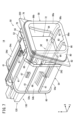
- FIG. 1 is an external schematic diagram of a storage device.
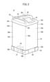
- FIG. 2 is a perspective view of a mobile battery.
- FIG. 3 is a plan view of the mobile battery.
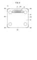
- FIG. 4 is a bottom view of the mobile battery.
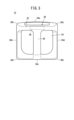
- FIG. 5 is a rear view of the rear surface of the front panel.
- FIG. 6 is a sectional view taken along line VI-VI in FIG.
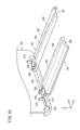
- FIG. 7 is a schematic overall perspective view of the slot.
- FIG. 8 is a cross-sectional side view of the slot.
- FIG. 9 is an enlarged perspective view of essential parts of the slot.
- FIG. 10 is a schematic perspective view of a first in-cylinder rail forming a second ridge portion.
- FIG. 11 is a cross-sectional view of the essential parts of the first in-cylinder rail.
- FIG. 10 is a schematic perspective view of a first in-cylinder rail forming a second ridge portion.
- FIG. 11 is a cross-sectional view of the essential parts of the first in-
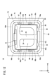
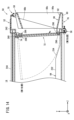
- FIG. 12 is a schematic front view of the slot.
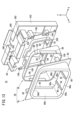
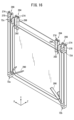
- FIG. 13 is an exploded perspective view of the bezel.
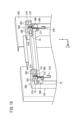
- FIG. 14 is a side cross-sectional view of the slot showing the movement trajectory of the door.
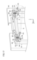
- FIG. 15 is a schematic perspective view of the essential part showing the structure of the mounting portion of the door in the slot when the door is positioned at the second position.
- FIG. 16 is a rear view of the door looking at the side facing the inside of the slot.
- FIG. 17 is a schematic perspective view of essential parts when the door is moved to the first position from the state of FIG. 15;
- FIG. 18 is an overall perspective view of a torsion spring that pushes the door.
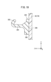
- FIG. 19 is a cross-sectional view of essential parts of the gasket.
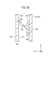
- FIG. 20 is a fragmentary cross-sectional view of a crushed gasket.
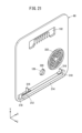
- FIG. 21 is a schematic perspective view of a bottom cover forming the bottom of the slot.
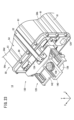
- Figure 22 is a schematic rear perspective view of the slot;
- Figure 23 is a schematic rear perspective view of the slot at another angle than Figure 22;
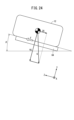
- FIG. 24 is an action diagram in which gravity acting on a mobile battery (electric device) inserted into a slot is exploded.
- FIG. 25 is a chart showing the relationship between the inclination angle of the slot with respect to the horizontal direction and the dynamic friction force of the first in-cylinder rail.
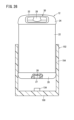
- FIG. 26 is a vertical cross-sectional view of an accommodation device according to another aspect.
- the accommodation device 10 (or holding device) shown in FIG. 1 will be exemplified and explained based on the X-axis, Y-axis and Z-axis defined as follows.
- the direction in which the mobile battery 12 is inserted into and removed from the slot 14 is defined as the Z-axis direction.
- the direction from the innermost part of the slot 14 toward the opening is defined as +Z-axis direction.
- the +Z-axis direction is the withdrawal direction in which the mobile battery 12 is removed from the slot 14 .
- the ⁇ Z-axis direction is the opposite direction to the +Z-axis direction.
- the ⁇ Z-axis direction is the direction in which the mobile battery 12 is inserted into the slot 14 . That is, the Z-axis direction is the insertion/removal direction of the mobile battery 12 .
- the direction parallel to the width direction of the accommodation device 10 is defined as the X-axis direction.
- the right hand side in the X-axis direction is the +X-axis direction.
- the ⁇ X-axis direction is the opposite direction to the +X-axis direction and is the left-hand side in the X-axis direction.
- a direction orthogonal to the Z-axis and the X-axis is defined as the Y-axis direction.
- the upper side is the +Y-axis direction.
- the lower side is the -Y-axis direction.
- the wording "insertable” is substantially synonymous with the wording "detachable”. That is, the mobile battery 12 can be attached (inserted) into the slot 14 and can be removed (pulled out) from the slot 14 .
- the term “detachable” means that the mobile battery 12 can be freely inserted into and removed from the slot 14 without the user using a tool or the like.
- the wording "insertion and removal” is synonymous with the wording "insertion and removal”. Therefore, "inserted and removed” or “attached and detached” are synonymous with “inserted and removed.”
- FIG. 1 is an external schematic view of the housing device 10.
- a mobile battery 12 power storage device
- This housing device 10 is a device that charges a mobile battery 12 housed inside the housing device 10 .
- the user pushes the mobile battery 12 with a low state of charge (SOC) into the storage device 10 .
- SOC state of charge
- the accommodation device 10 has 12 slots 14 (accommodation portions or holding portions) and one operation panel 16 .
- a mobile battery 12 is accommodated in each of the twelve slots 14 .
- the accommodation device 10 starts charging the mobile battery 12 accommodated in the slot 14 .
- the operation panel 16 is a device operated by the user. By operating the operation panel 16, the user pays a fee, for example.
- FIG. 2 is a perspective view of the mobile battery 12.
- FIG. 3 is a plan view of the mobile battery 12.
- FIG. 4 is a bottom view of the mobile battery 12.
- the mobile battery 12 has a bottom case 20, a main case 22, and a top case 24.
- the bottom case 20 , the main case 22 and the top case 24 constitute a housing for the mobile battery 12 .
- the bottom case 20 constitutes the bottom surface of the mobile battery 12 .
- the top case 24 constitutes the upper surface of the mobile battery 12.
- a handle 30 is provided on the upper surface.
- the handle 30 has a first gripping portion 28 and a second gripping portion 32 . The user grips the handle 30 and inserts/removes the mobile battery 12 into/from the slot 14 .
- the main case 22 is a square cylindrical hollow body with open ends (see FIG. 2). Therefore, mobile battery 12 has four sides.
- the four sides are side 34a, side 34b, side 34c and side 34d.
- a side surface 34a therein has an outwardly convex curved shape.
- the side surface 34 a is a surface corresponding to the second grip portion 32 .
- Sides 34b, 34c and 34d are substantially flat. Although the entire side surface 34a is curved in the illustrated example, a portion of the side surface 34a may be partially curved.
- a cell pack is accommodated in the main case 22 .
- a cell pack is configured by electrically connecting a plurality of unit cells. Since this configuration is known, for example, as described in Japanese Patent Application Laid-Open No. 2020-198229, illustration and description are omitted.
- a cell pack corresponds to the power storage unit of the present invention.
- the female connector 26 (first electrical terminal) is exposed on the bottom surface.
- the connector 26 has female electrical terminals for transmitting and receiving power and female communication terminals for transmitting and receiving communication signals. That is, the connector 26 serves as both an electrical terminal and a communication terminal.
- a connector 26 is provided in a recessed space 27 on the bottom surface. That is, the connector 26 is provided at a position slightly closer to the top case 24 from the bottom surface. The connector 26 is located from the center of the bottom surface toward the end where the second grip portion 32 is provided.
- a female connector 26 is sometimes called a receptacle.
- a light metal is selected as the material of the bottom case 20, the main case 22 and the top case 24.
- Suitable examples of light metals include aluminum or aluminum alloys. This is because aluminum or an aluminum alloy is lightweight and chemically stable.
- the storage device 10 has a housing 200 .
- the housing 200 has an apparatus main body 202 as a main part and a front panel 204 as a separate part.
- An exposure window 206 is formed as an opening in the front panel 204 .
- the number of exposed windows 206 is the same as the number of slots 14 .
- a bezel 70 that is part of the slot 14 is exposed through the exposure window 206 .
- the design surface 208 of the front panel 204 is shown.
- the design surface 208 is an arrangement surface of the outer surface of the front panel 204 that faces the user (+Z-axis direction). Therefore, the user visually recognizes the design surface 208 .
- the +Z-axis direction facing the user is the first direction.
- FIG. 5 and 6 show the back surface 210 of the front panel 204.
- FIG. A back surface 210 of the front panel 204 is a surface opposite to the design surface 208 and faces the apparatus body 202 .
- a rear surface 210 of the front panel 204 is provided with four U-shaped ribs 212 (reinforcing portions).
- the U-shaped rib 212 extends along the Y direction, which is the longitudinal direction of the front panel 204 .
- the opening of the U-shaped rib 212 faces the device body 202 .
- Two of the four U-shaped ribs 212 are provided at both ends in the X direction, which is the width direction.
- the remaining two of the four U-shaped ribs 212 are provided between two widthwise adjacent rows of exposure windows 206 .
- a plurality of (for example, four) strikers 214 are provided at a site different from the site where the U-shaped rib 212 is provided.
- the device main body 202 is provided with a latch (not shown). As the striker 214 is restrained by the latch, the front panel 204 is assembled to the device main body 202 .
- the inner peripheral edge of the exposed window 206 is burred over the entire circumference. Specifically, the inner peripheral edge of the exposure window 206 is folded back at an acute angle from the design surface 208 toward the back surface 210 facing the apparatus main body 202 . As a result, a folded portion 216 (so-called burring) is formed on the inner peripheral edge portion of the exposure window 206 . U-shaped ribs 212 and folds 216 provide front panel 204 with greater stiffness. The folded portion 216 encircles the inner peripheral edge of the exposure window 206 . In other words, the folded portion 216 is provided over the entire inner peripheral edge of the exposure window 206 .
- the folding angle of the folding portion 216 may be a right angle.
- the tip of the folded portion 216 is located on the outer periphery of the exposed window 206 . Therefore, the circumference of the tip of the folded portion 216 is longer than the circumference of the inner circumference of the exposure window 206 .
- the inner circumference of the exposure window 206 is longer than the inner circumference of the entrance/exit of the mobile battery 12 in the slot 14 .
- the entrance/exit of the slot 14 is the first insertion opening 86a shown in FIGS. 9 and 13 and the like. The first insertion opening 86a will be described later.
- the material of the front panel 204 is preferably a material that can be easily burred. Suitable examples of such materials include hard metals. A typical example of a hard metal is stainless steel.
- a gasket 220 shown in FIG. 9 is interposed between the outer surface of the slot 14 and the back surface 210 of the front panel 204 . Gasket 220 will be described later.
- FIG. 7 is a schematic overall perspective view of the slot 14.
- FIG. 7 shows a state in which the mobile battery 12 is not inserted into the slot 14.
- FIG. 8 is a cross-sectional side view of slot 14.
- FIG. 8 shows a state in which the mobile battery 12 is inserted into the slot 14.
- the slot 14 has a slot sleeve 50 and a battery lock mechanism 52.
- Slot sleeve 50 holds mobile battery 12 .
- the slot sleeve 50 has a slot body 54 , a slot flange 56 , a slot guide 58 and a bottom cover 60 .
- the slot body 54 is a tubular member (tubular portion) having a lower plate 54a, a left plate 54b, a right plate 54c, and an upper plate 54d.
- the slot body 54 extends along the Z-axis direction.
- the Z-axis direction is the insertion/removal direction of the mobile battery 12 .
- the slot body 54 is a hollow body having a substantially quadrangular prism shape. Therefore, when the slot body 54 is viewed from the Z-axis direction, the outer shape of the slot body 54 is substantially rectangular.
- the slot body 54 may be a substantially cylindrical hollow body. In this case, when the slot body 54 is viewed from the Z-axis direction, the outer shape of the slot body 54 is substantially circular.
- outer ribs 61 extending along the Z-axis direction are provided on the outer surfaces of the lower plate 54a, the left plate 54b, the right plate 54c, and the upper plate 54d.
- the outer ribs 61 improve the rigidity of the slot body 54 .
- the slot body 54 has a holding space 54e inside.
- the mobile battery 12 is held in the slot 14, most of the mobile battery 12 is held in this holding space 54e.
- the slot main body 54 corresponds to the tubular portion of the second member of the present invention.
- a member corresponding to the bottom of the second member is the bottom cover 60 .
- the cylindrical portion and the bottom portion of the second member are separate members.
- the second member which is a single member, integrally has the barrel portion and the bottom portion.
- the outer shape of the slot body 54 is substantially rectangular.
- the slot body 54 has an opening 54f at the end in the +Z-axis direction and an opening 54g at the end in the -Z-axis direction.
- an in-slot protrusion 62 is provided on the inner surface of the lower plate 54a.
- the in-slot ridge portion 62 has two first in-cylinder rails 64 .
- the first in-cylinder rail 64 protrudes vertically upward (+Y-axis direction) from the inner surface of the lower plate 54a.
- the two first in-cylinder rails 64 extend to the vicinity of the bottom cover 60 along the Z-axis direction while being separated from each other by a predetermined distance.
- the predetermined interval is constant. Therefore, the two first in-cylinder rails 64 are parallel to each other.
- the in-slot ridge portion 62 corresponds to the second ridge portion of the present invention.
- the number of the first in-cylinder rails 64 is two, but the number of the first in-cylinder rails 64 may be one. Alternatively, the number of first in-cylinder rails 64 may be three or more.
- the Z-axis direction is the insertion/removal direction of the mobile battery 12 .
- the Y-axis direction is a direction orthogonal to the Z-axis direction.
- the two first in-cylinder rails 64 protrude in a direction intersecting the insertion/removal direction of the mobile battery 12 and extend along the insertion/removal direction of the mobile battery 12 .
- the first in-cylinder rail 64 extends toward the bottom cover 60 .
- first in-cylinder rail 64 An internal space (not shown) is formed in the first in-cylinder rail 64 . That is, the first in-cylinder rail 64 is a hollow body. Therefore, an increase in the weight of the slot body 54 due to the provision of the first in-cylinder rail 64 is avoided.
- the first in-cylinder rail 64 has a rail main body portion 230 positioned in the slot main body 54 .
- a guide rail portion 232 extends in the +Y-axis direction from the upper surface of the rail body portion 230 facing the +Y-axis direction.
- the rail body portion 230 and the guide rail portion 232 extend along the Z-axis direction.
- a gently sloping inclined portion 234 is formed at the end (front end) of the guide rail portion 232 in the +Z-axis direction.
- the top surface of the inclined portion 234 faces the -Y-axis direction as it goes from the -Z-axis direction to the +Z-axis direction.
- the inclined portion 234 prevents the door 72 from interfering with the guide rail portion 232 during rotation. That is, the inclined portion 234 is a relief portion that prevents the door 72 from interfering with the guide rail portion 232 .
- the length of the inclined portion 234 along the Z-axis direction is set so that the inclined portion 234 is outside the movement locus of the door 72 .
- a rear tip 236 projecting in the -Z-axis direction is provided at the end (rear end) in the -Z-axis direction in the rail body portion 230 .
- the rear tip 236 is narrower than the rail body 230 .
- the first in-cylinder rail 64 stops moving in the -Z-axis direction.
- a relief hole 238 is formed in the rear tip 236 .
- the escape hole 238 has a shape of a rectangular prism that is hollowed out from the rear end 236 .
- the escape hole 238 has three openings, namely, the lower surface and the upper surface of the rear tip 236 facing the Y-axis direction, and the rear end surface of the rear tip 236 facing the -Z-axis direction.
- the opening in the lower surface of the rear tip end 236 (opening in the -Y-axis direction) is closed by the inner surface of the lower plate 54a of the slot body 54.
- the opening (communication hole 240 ) on the rear end face facing the ⁇ Z-axis direction faces the concave groove 310 .
- the +Z-axis direction end (front end) of the rail main body 230 is supported by the rail support member 242 shown in FIG.
- Suitable materials for the first in-cylinder rail 64 configured as described above include resins such as polyoxymethylene.
- Polyoxymethylene is also called polyacetal or POM.
- Polyamide 66 is exemplified as another resin that can be the material of the first in-cylinder rail 64 .
- a second in-cylinder rail 66 and a third in-cylinder rail 67 are provided on the inner surfaces of the left side plate 54b and the right side plate 54c of the slot body 54, respectively.
- the second in-cylinder rail 66 and the third in-cylinder rail 67 protrude in the horizontal direction (X-axis direction) from the inner surfaces of the left side plate 54b and the right side plate 54c, respectively.
- the second in-cylinder rail 66 and the third in-cylinder rail 67 are arranged vertically along the Y-axis direction on the inner surfaces of the left side plate 54b and the right side plate 54c, respectively.
- the second in-cylinder rail 66 and the third in-cylinder rail 67 extend to the vicinity of the bottom cover 60 along the Z-axis direction.
- the Z-axis direction is the insertion/removal direction of the mobile battery 12 .
- the X-axis direction is a direction perpendicular to the Z-axis direction.
- the second in-cylinder rail 66 and the third in-cylinder rail 67 protrude in a direction intersecting the insertion/removal direction of the mobile battery 12 and extend along the insertion/removal direction of the mobile battery 12 .
- the side surface 34 c of the mobile battery 12 abuts on the guide rail portions 232 of the two first in-cylinder rails 64 .
- the side surface 34b of the mobile battery 12 abuts on the second in-cylinder rail 66 and the third in-cylinder rail 67 provided on the left side plate 54b.
- a side surface 34d of the mobile battery 12 contacts a second in-cylinder rail 66 and a third in-cylinder rail 67 provided on the right side plate 54c.
- the mobile battery 12 is positioned within the slot main body 54 by the contact described above. When the number of first in-cylinder rails 64 is two or more, the posture of mobile battery 12 is further stabilized.
- a bezel 70 is attached to the opening 54f of the slot body 54 in the +Z-axis direction.
- the bezel 70 corresponds to the first member of the invention.
- the bezel 70 is a separate member from the slot body 54 and is connected to the slot body 54 adjacent to the slot body 54 .
- the location where the bezel 70 and the slot body 54 are divided is not particularly limited to the location shown in FIG.
- the dividing point between the bezel 70 and the slot body 54 can be in the ⁇ Z-axis direction rather than the door 72 .
- the bezel 70 which is the first member, is arranged at a position on the outside of the slot 14.
- the slot body 54 which is the second member, is arranged at a position inside the slot 14.
- the external side refers to the external side in the direction in which the mobile battery 12, which is an electrical device or a power storage device, is taken in and out of the first insertion port 86a, which is an entrance and exit.
- the inner side is the side opposite to the outer side. In the illustrated example, the outer side is in the +Z-axis direction and the inner side is in the -Z-axis direction.
- the bezel 70 has a slot flange 56 and a slot guide 58.
- Slot flange 56 corresponds to the second sub-member of the present invention.
- the slot guide 58 corresponds to the first sub-member of the invention.
- the slot flange 56 and the slot guide 58 are separate members.
- a packing 250 is interposed between the slot flange 56 and the slot guide 58 .
- the packing 250 has a frame shape.
- FIG. 13 is an exploded perspective view of the bezel 70.
- the slot guide 58 has an outer member 76 and an inner member 78 .
- the outer member 76 has a frame portion 80 , a collar portion 82 and a plurality of convex engaging portions 84 .
- the frame portion 80 has an annular shape (rectangular shape).
- the frame portion 80 is a hollow portion having an annular inner space (not shown). That is, the outer member 76 forming the bezel 70 is a hollow body having an annular internal space along the frame portion 80 .
- the annular internal space is a space that accommodates the inner member 78 .
- the frame portion 80 is formed with a first insertion port 86a (entrance) in the +Z-axis direction and a second insertion port 86b in the -Z-axis direction.
- the first insertion opening 86a and the second insertion opening 86b are separated by a distance corresponding to the thickness of the frame portion 80 along the Z-axis direction.
- the mobile battery 12 is inserted or pulled out from the first insertion port 86a.
- the frame portion 80 has a lower inner surface 88a, a left inner surface 88b, a right inner surface 88c and an upper inner surface 88d.
- the lower inner surface 88a, the left inner surface 88b, the right inner surface 88c and the upper inner surface 88d correspond to inner surfaces of the first member.
- the lower inner surface 88a and the upper inner surface 88d extend substantially horizontally.
- the left inner surface 88b and the right inner surface 88c extend in a direction intersecting the horizontal direction and the vertical direction at a predetermined angle.
- a bezel inner projection 90 is provided on the lower inner surface 88a.
- the in-bezel ridge 90 has two in-bezel rails 92 .
- the bezel inner rail 92 protrudes vertically upward (+Y-axis direction) from the lower inner surface 88a.
- the two inner-bezel rails 92 extend toward the bottom cover 60 along the Z-axis direction while being spaced apart from each other by a predetermined distance. The predetermined interval is constant. Therefore, the two in-bezel rails 92 are parallel to each other.
- the bezel inner ridge 90 corresponds to the first ridge of the present invention.
- two in-bezel rails 92 are exemplified, but the number of in-bezel rails 92 may be one. Alternatively, the number of in-bezel rails 92 may be three or more.
- the number of the bezel inner rails 92 is the same as the number of the first cylinder inner rails 64, and the bezel inner rails 92 are connected to the first cylinder inner rails 64 in the +Z-axis direction. However, it is not essential that the number of the bezel inner rails 92 and the number of the first cylinder inner rails 64 are the same.
- the ridge portion of the present invention includes the bezel inner rail 92 as the first ridge portion and the first cylinder inner rail 64 as the second ridge portion.
- the bezel inner rail 92 and the guide rail portion 232 of the first cylinder inner rail 64 may be continuous with each other along the Z-axis direction.
- the bezel inner rail 92 may be displaced from the first cylinder inner rail 64 in the ⁇ X-axis direction or the +X-axis direction.
- the Z-axis direction is the insertion/removal direction of the mobile battery 12 .
- the Y-axis direction is a direction perpendicular to the Z-axis direction.
- the two in-bezel rails 92 protrude in a direction intersecting the insertion/removal direction of the mobile battery 12 and extend along the insertion/removal direction of the mobile battery 12, similarly to the first in-cylinder rails 64. are doing.
- the bezel inner rail 92 is rounded, and the width along the X direction becomes smaller toward the +Z axis direction.
- the bezel inner rail 92 is a hollow body. Therefore, an increase in the weight of the slot body 54 due to the provision of the bezel inner rails 92 can be avoided.
- the side surface 34c of the mobile battery 12 is in sliding contact with the rails 92 inside the bezel.
- the attitude of mobile battery 12 is stabilized.
- Protruding portions 94 are formed on the left inner surface 88b and the right inner surface 88c of the frame portion 80, respectively.
- a protruding portion 94 formed on the left inner surface 88b has a convex shape protruding toward the right inner surface 88c.
- a protruding portion 94 formed on the right inner surface 88c has a convex shape protruding toward the left inner surface 88b.
- the protrusion 94 extends from the lower inner surface 88a toward the upper inner surface 88d. However, the length in the extending direction (the length along the Y-axis direction) of the projecting portion 94 is smaller than the distance from the lower inner surface 88a to the upper inner surface 88d.
- the protruding length (the length along the X-axis direction) of the protruding portion 94 is a length that allows contact with the side surfaces 34b and 34d of the main case 22.
- the protruding length (the length along the X-axis direction) of the protruding portion 94 is such that it is slightly separated from the side surfaces 34b and 34d of the main case 22 .
- the shape of the protrusion 94 corresponds to the shape of the recess 38 of the mobile battery 12 .
- the flange portion 82 is an extension portion that extends outward from the outer edge of the frame portion 80 in an annular (rectangular) shape.
- the collar portion 82 is formed thin.
- the convex engaging portion 84 is mainly provided on the collar portion 82 .
- the convex engagement portion 84 protrudes toward the slot flange 56 ( ⁇ Z axis direction).
- the material of the outer member 76 is preferably a material with lower hardness than the materials of the bottom case 20, the main case 22 and the top case 24 of the mobile battery 12.
- a suitable example of the material of the outer member 76 is a resin such as polycarbonate.
- the material of the bezel inner rail 92 and the projecting portion 94 is also resin such as polycarbonate.
- the material of the first in-cylinder rail 64 is resin such as POM or polyamide 66, for example.
- the material of the first in-cylinder rail 64 is the bottom case 20, the main case 22 and the top case. It has a lower hardness than the No. 24 material.
- Resin can be selected as the material for the bottom case 20 and the top case 24 in the mobile battery 12 .
- a resin having a hardness lower than that of the bottom case 20 and top case 24 can be selected.
- the bottom case 20 and A resin having a higher hardness than the material resin of the top case 24 may be selected.
- the outer member 76 exhibits translucency.
- translucent means the property of transmitting visible light. That is, the outer member 76 has a property of transmitting visible light.
- Outer member 76 may be transparent.
- Outer member 76 may be opaque. Since the outer member 76 exhibits translucency, the user can visually recognize the light emitted by the light emitting portion 98 from the outside of the outer member 76 .
- the light emitting section 98 will be described later.
- the entire outer member 76 may be translucent. Alternatively, only the portion of the outer member 76 corresponding to the light emitting portion 98 may be translucent.
- the inner member 78 has an annular shape (rectangular shape).
- a light-emitting portion 98 is provided on a side portion of the inner member 78 in the +X-axis direction.
- Another light-emitting portion 98 is provided on the side portion of the inner member 78 in the ⁇ X-axis direction.
- the two light emitting portions 98 are arranged at positions facing each other on the inner member 78 and extend along the vertical direction.
- the light-emitting unit 98 indicates the vacancy of the slot 14, the charging state of the mobile battery 12 housed in the slot 14, and the like, in a state in which the light is on, a state in which the light is blinking, and a state in which the light is off. , color of light, etc.
- the inner member 78 has a connecting structure 99 .
- the wide lower portion of the inner member 78 located in the ⁇ Y-axis direction is a connecting portion 100 that connects the two light emitting portions 98 .
- the narrow upper portion of the inner member 78 located in the +Y-axis direction is another connecting portion 100 that connects the two light emitting portions 98 .
- the connecting structure 99 has two connecting parts 100 .
- An annular shape (rectangular shape) having an opening 102 is formed by the two connecting portions 100 and the two light emitting portions 98 .
- the strength of the light-emitting portions 98 is improved. Moreover, since the light-emitting portion 98 and the inner member 78 can be handled integrally, it is easy to assemble the bezel 70 . When the two connecting portions 100 and the two light emitting portions 98 form an annular shape (rectangular shape), the strength is further improved.
- the slot flange 56 is a substantially rectangular annular body.
- the slot flange 56 has a third insertion opening 104 .
- the third insertion port 104 continues to the second insertion port 86b.
- the mobile battery 12 inserted from the first insertion port 86a passes through the third insertion port 104 via the second insertion port 86b.
- the slot flange 56 is provided with a concave engaging portion 106 at a position corresponding to the position of the convex engaging portion 84 in the slot guide 58 .
- the outer member 76 of the slot guide 58 and the slot flange 56 are connected to each other.
- the inner member 78 of the slot guide 58 is housed in the annular inner space of the outer member 76 .
- the rest of the bezel inner rail 92 is provided on the lower inner surface of the slot flange 56 .
- the bezel inner ridge portion 90 (first ridge portion) is provided from the slot guide 58, which is the first sub-member, to the slot flange 56, which is the second sub-member.
- the bezel inner rails 92 provided on the slot guide 58 and the bezel inner rails 92 provided on the slot flange 56 are connected along the Z-axis direction.
- the bezel inner rails 92 provided on the slot guide 58 are positioned in the +Z-axis direction, and the bezel inner rails 92 provided on the slot flange 56 are positioned in the -Z-axis direction.
- the material of the slot flange 56 is preferably a material having lower hardness than the materials of the bottom case 20, the main case 22 and the top case 24 of the mobile battery 12, similarly to the outer member 76.
- a preferred embodiment of the material for slot flange 56 is polycarbonate.
- the material of the bezel inner rail 92 is also polycarbonate. Note that, similarly to the bezel inner rails 92 provided on the outer member 76, the bezel inner rails 92 provided on the slot flange 56 are also hollow portions having internal spaces.
- a door 72 is attached to the slot flange 56 as shown in FIGS.
- the door 72 is positioned inside the slot 14 relative to the first insertion opening 86 a that is the entrance/exit for the mobile battery 12 .
- the door 72 is in the second position as shown in FIGS. 7 and 14.
- FIG. In this embodiment, the second position is the fully closed position.
- the amount of blockage of the first insertion opening 86a by the door 72 is the largest.
- the door 72 opens inside the slot body 54 as shown in FIG. In this case, the door 72 is located at the first position. In this embodiment, the first position is the fully open position.
- FIG. 14 shows the locus of movement of the one end serving as the center of rotation and the other end on the opposite side of the door 72 .
- the door 72 opens and closes by rotating around a shaft 74 that is a rotating shaft.
- the +Y-axis direction end of the slot flange 56 is provided with two flange-side support portions 260 extending along the -Z-axis direction.
- one flange-side support portion 260 has four support pieces 262 spaced apart from each other at predetermined intervals.
- two first door-side support portions 264 and two second door-side support portions 266 are provided at the +Y-axis direction end portion of the door 72 .
- One first door-side support portion 264 has two insertion pieces 268 spaced apart from each other at a predetermined interval.
- one second door side support portion 266 has two insertion pieces 270 spaced apart from each other by a predetermined distance.
- the second door-side support portion 266 is located outside the first door-side support portion 264 .
- the first door side support portion 264 (two insertion piece portions 268) is inserted into the first space 271 between the two support piece portions 262 adjacent to each other.
- the second door-side support portion 266 (two insertion piece portions 270) is similarly inserted into the second space 272 between the two support piece portions 262 adjacent to each other.
- the second space 272 is a space separate from the first space 271 .
- a support hole 274 is formed through all the support piece portions 262 and all the insertion piece portions 268 and 270 along the X direction.
- the shaft 74 is rotatably inserted through the support hole 274 . By this insertion, the door 72 is supported by the slot flange 56 via the shaft 74 .
- the shaft 74 is provided with a torsion spring 278 that is an elastic member.
- the torsion spring 278 includes a spiral portion 280 wound in a spiral shape, a first leg portion 282 extending from one end of the spiral portion 280 , and extending from the other end of the spiral portion 280 . and a second leg 284 .
- the shaft 74 is passed through the spiral portion 280 (see FIG. 15).
- the spiral portion 280 is inserted into a third space 286 between two adjacent support piece portions 262 in the flange side support portion 260 .
- the third space 286 is a space separate from the first space 271 and the second space 272 .
- the second leg 284 is longer than the first leg 282.
- a linear portion 288 extending linearly is interposed between the spiral portion 280 and the second leg portion 284 .
- the second leg portion 284 extends in a direction bent with respect to the straight portion 288 .
- a hook portion 282 a of the first leg portion 282 is hooked on a predetermined portion of the slot flange 56 . This hook prevents rotation of the first leg portion 282 .
- the hook portion 284 a of the second leg portion 284 is hooked on a predetermined portion of the first door-side support portion 264 of the door 72 . Therefore, the second leg portion 284 rotates integrally with the door 72 .
- the door 72 is a substantially rectangular body having four sides. Therefore, corners 72a to 72d are formed on the four sides of the door 72, respectively. In other words, the door 72 has four corners 72a-72d.
- V-shaped ribs 290 protruding in the -Z-axis direction are provided as reinforcements at the two corners 72a and 72b located at the lower ends in the -Y-axis direction.
- the V-shaped ribs 290 extend inwardly of the door 72 from the corners 72a, 72b.
- the extending direction of the V-shaped rib 290 is inclined with respect to the X-axis direction and the Y-axis direction.
- plate-shaped ribs 292 protruding in the -Z-axis direction are provided as reinforcing parts in two corners 72c and 72d located at the upper end in the -Y-axis direction.
- the plate-shaped rib 292 extends along the Y-axis direction.
- the plate-shaped rib 292 continues to the insertion piece portion 268 that constitutes the first door-side support portion 264 .
- the two V-shaped ribs 290 and the two plate-shaped ribs 292 increase the rigidity of the corners 72a to 72d of the door 72. Therefore, the corners 72a to 72d of the door 72 are less likely to be damaged.
- a plurality of door-side magnets 298 shown in FIG. 8 are provided on the end face of the door 72 facing the slot flange 56 in the +Z-axis direction.
- the flange-side magnet 296 corresponds to the first magnetic force holding portion or the first magnet of the present invention.
- the door-side magnet 298 corresponds to the second magnetic force holding portion or the second magnet of the present invention.
- the slot 14, which is the accommodation portion has the first magnet and the second magnet.
- the flange-side magnet 296 and the door-side magnet 298 approach each other and attract each other by magnetic force.
- the flange-side magnet 296 and the door-side magnet 298 are attracted to each other based on magnetic force, for example.
- the number of flange-side magnets 296 and door-side magnets 298 is four.
- Either one of the flange-side magnet 296 and the door-side magnet 298 may be replaced with a magnetic body that can be attracted by a magnet.
- a metal exhibiting ferromagnetism is exemplified.
- a specific example of the metal is iron or the like.
- a substantially rectangular gasket 220 is attached to the frame portion 80 that constitutes the outer member 76 of the slot guide 58 .
- the gasket 220 corresponds to the interposed portion of the present invention.
- the gasket 220 has a frame-shaped body 300 , an annular hook 302 , and a bridge 304 connecting the frame-shaped body 300 and the annular hook 302 .
- the frame-shaped body portion 300 is an endless loop portion that continues in a frame shape at the base end portion of the annular hook portion 302 .
- the end of the frame-shaped main body 300 in the ⁇ Z-axis direction is a flat portion 306 having a flat surface.
- the flat portion 306 abuts on the end surface of the flange portion 82 (extending portion) on the +Z-axis direction side.
- the circumference of the inner circumference of the flat portion 306 is longer than the circumference of the inner circumference of the first insertion opening 86a.
- the first insertion port 86a is the entrance/exit for the mobile battery 12 in the slot 14 as described above.
- the bridge portion 304 extends in the +Z-axis direction.
- the annular hook portion 302 is bent from the tip of the bridge portion 304 on the +Z-axis direction toward the outside of the bridge portion 304 or the gasket 220 .
- a worker who assembles the storage device 10 assembles the slot 14 into the device main body 202 and then assembles the front panel 204 into the device main body 202 .
- the operator presses the front panel 204 toward the apparatus body 202 .
- the annular hook portion 302 and the bridge portion 304 are easily bent toward the outside of the gasket 220 .
- a portion of gasket 220 is easily crushed with a small force. Therefore, the operator can press the front panel 204 against the apparatus main body 202 with a small force. That is, the work of assembling the front panel 204 to the device main body 202 is facilitated.
- the front panel 204 is connected to the device body 202 via the striker 214 (see FIG. 5) and the latch, the gasket 220 is interposed between the outer member 76 and the front panel 204 in the state shown in FIG.
- a substantially rectangular rail support member 242 is arranged in the -Z-axis direction of the slot flange 56 .
- the end surface of the rail support member 242 facing the ⁇ Z axis direction supports the tip (front end) of the first in-cylinder rail 64 on the +Z axis direction side.
- a bottom cover 60 (bottom) is attached to the opening 54g of the slot body 54 in the -Z-axis direction.
- a connector unit 120 , a fan 122 , an electronic circuit board 124 and a detection switch 126 are attached to the bottom cover 60 .
- the bottom cover assembly 130 is thus configured. Bottom cover assembly 130 will be described later.
- the -Y-axis direction end (lower end) of the bottom cover 60 is provided with a groove 310 extending along the X-axis direction.
- the concave groove 310 is recessed in the ⁇ Z-axis direction from the +Z-axis direction side end face of the bottom cover 60 .
- a first discharge hole 312 is formed in the concave groove 310 at the end face of the bottom cover 60 on the ⁇ Z axis direction side.
- the concave groove 310 communicates with the internal space of the device main body 202 via the first discharge hole 312 .
- the filtering member 314 may be detachably accommodated in the concave groove 310 .
- two ribs 316 provided on the end face of the bottom cover 60 on the +Z-axis direction side may press a part of the filter member 314 exposed from the groove 310 from above.
- a specific example of the material of the filtering member 314 is a sponge-like porous member such as a sponge filter.
- a second discharge hole 318 is formed through the bottom cover 60 along the Z-axis direction.
- the second discharge hole 318 has a substantially fan shape and is positioned on the side of the concave groove 310 in the -X-axis direction.
- the second discharge hole 318 communicates between the holding space 54e of the slot 14 and the internal space of the device body 202 .
- An insertion hole 320 and a ventilation hole 322 are formed in the bottom cover 60 .
- a detection portion of the detection switch 126 is inserted into the insertion hole 320 .
- the ventilation hole 322 is a hole for sending cooling air generated by the fan 122 into the slot 14 .
- a through hole 132 is formed in the bottom cover 60 .
- a connector 134 which will be described later, passes through the through hole 132 .
- the connector 134 passes through the through hole 132 so as to move from the -Z axis direction to the +Z axis direction.
- the connector 134 passes through the through hole 132 from the +Z-axis direction to the -Z-axis direction.
- a battery lock mechanism 52 is attached to the +Y-axis direction side of the slot flange 56 .
- the battery lock mechanism 52 restricts movement of the mobile battery 12 in the +Z-axis direction. This prevents the user from pulling out the mobile battery 12 from the slot 14 .
- the battery lock mechanism 52 allows the mobile battery 12 to move in the +Z-axis direction. Thereby, the user can pull out the mobile battery 12 from the slot 14 .
- the bottom cover assembly 130 is described. As shown in FIG. 22 , the bottom cover 60 is provided with a fan 122 and a connector unit 120 . A fan 122 facilitates airflow inside the slot sleeve 50 .
- the connector unit 120 has a connector 134 (second electrical terminal) and a motor 136 shown in FIG.
- Connector 134 which is male, has male electrical terminals for transmitting and receiving power and male communication terminals for transmitting and receiving communication signals. That is, the connector 134 serves as both an electrical terminal and a communication terminal. Connectors 134 that are male are sometimes called plugs.
- the connector 134 fits into the connector 26 of the mobile battery 12 . At this time, power is supplied from the connector 134 to the mobile battery 12 to charge the mobile battery 12 . Alternatively, the power of the mobile battery 12 is taken out through the connector 134 and the mobile battery 12 is discharged. Furthermore, the mobile battery 12 and a controller (not shown) of the storage device 10 are communicably connected via the connector 26 and the connector 134 . That is, communication signals are exchanged between the mobile battery 12 and the controller of the storage device 10 .
- the connector 134 advances or retreats along the Z-axis direction by a motor 136 .
- motor 136 has a rotating shaft (not shown).
- a rotating shaft extends from the motor 136 in the +Y direction.
- a pinion 138 shown in FIG. 23 is attached to the tip of the rotating shaft. Pinion 138 meshes with rack 140 .
- Motor 136 is mechanically connected to connector 134 via pinion 138 , rack 140 and base 142 .
- Connector 134 and motor 136 are attached to bottom cover 60 via base 142 . The motor 136 is thereby supported by the bottom cover 60 .
- the electronic circuit board 124 controls charging of the mobile battery 12 housed in the slot sleeve 50, for example.
- a detection switch 126 (see FIG. 8) is mounted on the electronic circuit of the electronic circuit board 124 . When the mobile battery 12 is held in the slot sleeve 50, the detection switch 126 is pushed down by the mobile battery 12 and switched from off to on.
- the end in the +Z-axis direction is exposed through the exposure window 206 of the front panel 204 .
- the slot 14 assembled in the device main body 202 is inclined with respect to the vertical direction (the direction of gravity).
- the top of the slot 14 is located farther from the user than the bottom of the slot 14 is.
- FIG. 24 shows the gravitational force G acting on the mobile battery 12 inserted in the slot 14 as a first force component (component) YG directed in the -Y-axis direction and a second force component (component) directed in the -Z-axis direction.
- FIG. 10 is an operation diagram disassembled into ZG.
- the second force component ZG is smaller than the dynamic friction force F of the first in-cylinder rail 64, the mobile battery 12 with the bottom case 20 inserted into the slot 14 must be moved in the ⁇ Z-axis direction by the user. It is necessary to apply a pushing force to the battery 12 .
- the mobile battery 12 with the bottom case 20 inserted into the slot 14 moves in the -Z-axis direction due to its own weight. do. In this case, it is easy to insert the entire mobile battery 12 into the slot 14 .
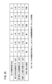
- FIG. 25 is a chart showing the relationship between the second component force ZG and the dynamic frictional force F of the first in-cylinder rail 64 when the inclination angle ⁇ of the slot 14 with respect to the horizontal direction is changed.
- the inclination angle ⁇ is 0°, it means that the slots 14 extend along the horizontal direction.
- the inclination angle ⁇ is 90°, it means that the slot 14 extends along the vertical direction.
- FIG. 25 shows the results of calculations assuming that the weight of the mobile battery 12 is 10 kgf and the dynamic friction coefficient of the first in-cylinder rail 64 is 0.18.
- the second component force ZG acting on the mobile battery 12 becomes the dynamic friction of the first in-cylinder rail 64. greater than the force F.
- the mobile battery 12 moves in the ⁇ Z-axis direction within the slot due to its own weight. Therefore, there is no particular need for the user to apply a pushing force to the mobile battery 12 . Therefore, it is easy to insert the entire mobile battery 12 into the slot 14 .
- the second force component ZG increases as the tilt angle ⁇ increases.
- the mobile battery 12 moves faster within the slot 14 . Therefore, there is a concern that the bottom surface of the mobile battery 12 may vigorously abut against the bottom cover 60 .
- the tilt angle ⁇ is set within an appropriate angle range.
- the accommodation device 10 according to this embodiment is basically configured as described above. Next, the effects of the storage device 10 will be described.
- the user When the SOC of the mobile battery 12 drops, the user inserts the mobile battery 12 into the empty slot 14 in the storage device 10 . At this time, the user holds the handle 30 and lifts the mobile battery 12 . The user orients the bottom case 20 toward the slot 14 and tilts the mobile battery 12 . Also, the user directs the side surface 34a, which is a convex curved surface, vertically upward. As a result, the bottom case 20 is at the low position and the top case 24 is at the high position with the side surface 34a facing vertically upward.
- the side surface 34a which is a convex curved surface
- the user then inserts the bottom case 20 into the first insertion opening 86a of the slot guide 58 (see FIGS. 7, 8 and 9).
- the side surface 34c faces vertically downward and the side surface 34a faces vertically upward.
- the bottom case 20 moves through the second insertion opening 86b to the third insertion opening 104 (see FIG. 13).
- two inner bezel rails 92 are provided on the lower inner surface 88 a of the slot guide 58 and the lower inner surface of the slot flange 56 . Therefore, the side surface 34 c of the bottom case 20 abuts on the upper surfaces of the two inner-bezel rails 92 .
- the direction in which the load of the mobile battery 12 acts is vertically downward. Therefore, the two in-bezel rails 92 bear the load of the mobile battery 12 .
- the user pushes the mobile battery 12 toward the holding space 54e.
- This push moves the mobile battery 12 toward the holding space 54e. Therefore, the side surface 34 c of the mobile battery 12 is in sliding contact with the rails 92 inside the bezel.
- the material of the bezel inner rails 92 has a lower hardness than the materials of the bottom case 20, the main case 22 and the top case . Therefore, it is possible to prevent the mobile battery 12 from being scratched.
- the bezel inner rail 92 If the bezel inner rail 92 is not provided, the side surface 34c of the mobile battery 12 is in sliding contact with substantially the entire lower inner surface 88a of the slot guide 58. Therefore, in this case, substantially the entire lower inner surface 88a is worn. As a result, abrasion powder is likely to be generated. Also, the lower inner surface 88a is easily scratched.
- the side surface 34c of the mobile battery 12 is in sliding contact with the upper surface of the rails 92 inside the bezel. Therefore, in this embodiment, wear of the lower inner surface 88a is avoided. In other words, the in-bezel rails 92 wear preferentially.
- the contact area between the two members when the side surface 34c slides on the upper surface of the bezel inner rail 92 is smaller than the contact area between the two members when the side surface 34c slides on the entire lower inner surface 88a. Therefore, the amount of abrasion powder generated is reduced.
- the occurrence of scratches on the lower inner surface 88a is also avoided. Since the rails 92 in the bezel bear the load of the mobile battery 12, wear of the left inner surface 88b, the right inner surface 88c and the upper inner surface 88d is also avoided. Also, the left inner surface 88b, the right inner surface 88c and the upper inner surface 88d are prevented from being scratched. Therefore, the aesthetic appearance of the slot guide 58 and the slot flange 56 is maintained.
- the bezel inner rail 92 is provided from the slot guide 58 to the slot flange 56 . Therefore, the bezel inner rail 92 extends from the first insertion opening 86 a to the opening 54 f of the slot body 54 . Therefore, it is easy to move the mobile battery 12 to the holding space 54e.
- the bottom case 20 reaches the opening 54f of the slot body 54.
- a first in-cylinder rail 64 is provided on the inner surface of the lower plate 54 a of the slot body 54 . Accordingly, the bottom case 20 is transferred from the bezel inner rail 92 to the first cylinder inner rail 64 .
- the bottom case 20 comes into sliding contact with the upper surface of the guide rail portion 232 of the first in-cylinder rail 64 .
- the main case 22 slides on the upper surface of the rails 92 inside the bezel.
- the main case 22 comes into sliding contact with the upper surface of the first in-cylinder rail 64 .
- the top case 24 slides on the upper surface of the rails 92 inside the bezel.
- the four corners 36b of the bottom case 20 and the four corners 36t of the top case 24 form a clearance 96a between the protrusion 94 and the lower inner surface 88a and a clearance 96a between the protrusion 94 and the upper inner surface 88d. and a clearance 96b (see FIG. 9). That is, the four corners 36 b of the bottom case 20 and the four corners 36 t of the top case 24 do not interfere with the projecting portion 94 .
- a second in-cylinder rail 66 and a third in-cylinder rail 67 are in contact with the side surfaces 34b and 34d of the mobile battery 12 housed in the holding space 54e, respectively.
- the projecting tip of the projecting portion 94 also abuts or approaches the side surface 34b and the side surface 34d. Therefore, the mobile battery 12 is positioned by the two second in-cylinder rails 66 , the two third in-cylinder rails 67 and the two projections 94 .
- the connectors 26 and 134 are aligned.
- the battery lock mechanism 52 When the mobile battery 12 is accommodated in the holding space 54e, the battery lock mechanism 52 operates. The mobile battery 12 is positioned and fixed by the battery lock mechanism 52 . Also, the detection switch 126 is switched from off to on. As a result, the motor 136 starts. This causes connector 134 to move toward connector 26 . Connector 134 engages connector 26 through through hole 132 .
- a light-emitting structure for example, lights up in another slot 14 .
- Another slot 14 is a slot 14 that accommodates a mobile battery 12 with a sufficiently high SOC. The user pulls out the mobile battery 12 from the slot 14 with the lighting structure lit.
- a light emitting section 98 is arranged near the first insertion opening 86a. Therefore, the user can easily recognize the first insertion opening 86a, which is the starting position for removing the mobile battery 12, based on the lighting position of the light emitting unit 98.
- FIG. 1 is the first insertion opening 86a.
- the top case 24, the main case 22 and the bottom case 20 come into sliding contact with the rails 92 in the bezel in this order. Also in this case, for the same reason as above, the amount of abrasion powder generated is reduced. In addition, since it is possible to avoid scratches on parts other than the rails 92 in the bezel, the appearance of the slot guide 58 and the slot flange 56 is maintained.
- the wear amount of the rails 92 inside the bezel may exceed the allowable range.
- the maintenance worker replaces the slot guide 58 and slot flange 56 with new ones.
- the bezel 70 and the slot main body 54 are formed as separate members in this way, it is possible to replace only the bezel 70 . Therefore, the maintenance cost is reduced when the amount of wear of the rails 92 in the bezel exceeds the allowable range.
- the door 72 is positioned at the second position (fully closed position).
- the door 72 is positioned at the second position, at least a portion of the door 72 is arranged on the trajectory along which the mobile battery 12 is inserted into and removed from the holding space 54e. With the door 72 arranged in this manner, the door 72 is pushed open by the mobile battery 12 when the mobile battery 12 is inserted into the holding space 54e.
- the door 72 By inserting the mobile battery 12 into the holding space 54e, the door 72 is positioned at the first position (fully open position) as shown in FIGS. At this time, the torsion spring 278 (see FIG. 15) pushes the door 72 back to the second position.
- the torsion spring 278 pushes the door 72 toward the second position. Therefore, as the mobile battery 12 moves in the +Z-axis direction, the door 72 returns from the first position to the second position.
- the door 72 is released from the pressure of the mobile battery 12 . Therefore, the door 72 returns to the second position and closes the first insertion opening 86a. Also in this process, the door 72 does not interfere with the guide rail portion 232 .
- the door 72 is not limited to a door that opens and closes by rotating about the shaft 74 .
- the door 72 may be a door that opens and closes based on parallel movement in the X-axis direction or the Y-axis direction.
- a relief hole 238 is formed in the rear end 236 of the first in-cylinder rail 64, as shown in FIG.
- Rainwater or the like flowing along the rail main body 230 flows into the groove 310 through the communication hole 240 of the escape hole 238 .
- Rainwater or the like passes through the filtering member 314 and is discharged to the outside of the slot body 54 through the first discharge holes 312 .
- the bezel inner rail 92 may be provided on the left inner surface 88b, the right inner surface 88c, or the upper inner surface 88d.
- This embodiment exemplifies the accommodation device 10 in which the connector 134 is provided so as to be movable forward and backward.
- the connector 134 may be positioned and secured to the bottom 150 as shown in FIG.
- the storage device or holding device is not particularly limited to the storage device 10 (battery exchange) shown in FIG.
- Another aspect of the containing device or holding device is a device that inputs power to the mobile battery 12 .
- it is a charging device, a charging/discharging device, or the like.
- the charging device, charging/discharging device, or the like may be of a movable type or may be of a stationary type.
- FIG. 26 shows a slot-type charging device 152 which is another form of a containment or holding device.
- the slot-type charging device 152 has a cylindrical portion 154 and a bottom portion 150 integrally formed.
- the storage device or holding device may be a device that outputs power from the mobile battery 12.
- Examples of such storage devices or holding devices include moving bodies such as electric vehicles, outboard motors, and aircraft.
- Electric vehicles include passenger vehicles such as two-wheeled vehicles, three-wheeled vehicles, and four-wheeled vehicles. Electric vehicles also include work vehicles such as lawn mowers, carts, and snow removers. Air vehicles include drones or aircraft.
- An outboard motor is a propulsion device used in a ship.
- a storage device or holding device that outputs power is a power feeder that uses the mobile battery 12 as a power source.
- the feeder may be movable and portable.
- the feeder may be stationary.
- the substantially rectangular parallelepiped slot 14 is exemplified as the holding portion.
- the holding portion may have a cylindrical shape with curved sides.
Landscapes
- Chemical & Material Sciences (AREA)
- Chemical Kinetics & Catalysis (AREA)
- Electrochemistry (AREA)
- General Chemical & Material Sciences (AREA)
- Engineering & Computer Science (AREA)
- Manufacturing & Machinery (AREA)
- Microelectronics & Electronic Packaging (AREA)
- Power Engineering (AREA)
- Battery Mounting, Suspending (AREA)
Abstract
An accommodation device (10) includes an accommodation unit (14) in which a power storage device (12) is accommodated in an insertable manner. The accommodation unit is formed in a bottomed cylinder shape having inner surfaces. Ridges (90) are provided on the inner surface of the accommodation unit, between an opening (86a) and a bottom section (60). The ridges extend in a direction from the opening of the accommodation unit (14) towards the bottom section.
Description
本発明は、収容部に蓄電装置を収容する収容装置に関する。
The present invention relates to an accommodation device that accommodates a power storage device in an accommodation portion.
国際公開第2020/262630号には、モバイルバッテリを収容する保持装置が開示されている。モバイルバッテリは、電力を蓄えた蓄電装置である。保持装置は、モバイルバッテリに対して充電を行う。又は、保持装置は、モバイルバッテリから供給された電力を外部負荷に供給する。
International Publication No. 2020/262630 discloses a holding device that houses a mobile battery. A mobile battery is a power storage device that stores electric power. The holding device charges the mobile battery. Alternatively, the holding device supplies power supplied from the mobile battery to the external load.
この保持装置は、複数個のスロット(収容部)を有する。モバイルバッテリは、複数個のスロットの各々に対して挿抜可能である。ユーザは、例えば、充電率(SOC: State of Charge)が低くなったモバイルバッテリを1個のスロットに挿入する。ユーザは、SOCが十分に高くなった別のモバイルバッテリを別の1個のスロットから引き抜く。
This holding device has a plurality of slots (accommodating portions). A mobile battery can be inserted into and removed from each of the plurality of slots. A user inserts, for example, a mobile battery with a low state of charge (SOC) into one slot. The user pulls out another mobile battery whose SOC has become sufficiently high from another slot.
国際公開第2020/262630号の図7及び図9に示されるように、スロットは、モバイルバッテリを挿抜するための開口が形成された部材を有する。モバイルバッテリをスロット内に挿入するとき、ユーザは、モバイルバッテリの底部の一辺を該部材に当接させる。これにより、該部材がモバイルバッテリの重量の一部を負担する。ユーザは、この状態で、モバイルバッテリの一側面(鉛直下方を向く面)を該部材に摺接させながら、モバイルバッテリをスロット内に押し入れる。これとは逆に、ユーザがモバイルバッテリをスロットから引き抜くとき、モバイルバッテリの前記一側面(鉛直下方を向く面)が前記部材に摺接する。
As shown in FIGS. 7 and 9 of International Publication No. 2020/262630, the slot has a member with an opening for inserting and removing the mobile battery. When inserting the mobile battery into the slot, the user brings one side of the bottom of the mobile battery into contact with the member. As a result, the member bears part of the weight of the mobile battery. In this state, the user pushes the mobile battery into the slot while sliding one side of the mobile battery (the side facing vertically downward) against the member. Conversely, when the user pulls out the mobile battery from the slot, the one side surface of the mobile battery (the side facing vertically downward) comes into sliding contact with the member.
上記の挿抜に伴ってモバイルバッテリが前記部材に摺接することにより、前記部材が摩耗して摺接痕が形成される懸念がある。また、摩耗によって摩耗粉が発生した場合、収容部内が摩耗粉で汚れる。
As the mobile battery comes into sliding contact with the member during the above insertion and removal, there is a concern that the member may be worn and a sliding contact mark may be formed. In addition, when abrasion powder is generated due to abrasion, the inside of the accommodating portion is stained with the abrasion powder.
本発明は、上述した課題を解決することを目的とする。
An object of the present invention is to solve the above-mentioned problems.
本発明の一実施形態によれば、蓄電部を有する蓄電装置を挿抜可能に収容する収容部を備える収容装置であって、前記収容部は、開口と、前記開口が形成された筒部と、前記筒部に連なる底部とを有し、前記開口、前記筒部及び前記底部によって、有底筒状に形成され、前記収容部の内面において、前記開口と前記底部との間に、前記内面から突出する1以上の突条部が設けられ、前記突条部は、前記開口から前記底部に向かう方向に沿って延在するように設けられる、収容装置が提供される。
According to one embodiment of the present invention, there is provided a housing device including a housing section for detachably housing a power storage device having a power storage section, wherein the housing section includes an opening, a tubular section in which the opening is formed, and a bottom portion connected to the cylindrical portion, the opening, the cylindrical portion, and the bottom portion forming a bottomed cylindrical shape. A storage device is provided, wherein one or more protruding ridges are provided, said ridges being provided to extend along a direction from said opening toward said bottom.
突条部が設けられていない場合、蓄電装置が収容部に対して挿抜されるとき、該蓄電装置は、収容部の内面に摺接する。これに対し、本発明においては、蓄電装置が収容部に対して挿抜されるとき、該蓄電装置は突条部に摺接する。蓄電装置と突条部との接触面積は、蓄電装置と収容部の内面との接触面積に比べて小さい。このため、摩耗粉の発生量が低減する。
If the ridge portion is not provided, the power storage device comes into sliding contact with the inner surface of the housing portion when the power storage device is inserted into or removed from the housing portion. On the other hand, in the present invention, when the power storage device is inserted into and removed from the accommodating portion, the power storage device comes into sliding contact with the ridge portion. A contact area between the power storage device and the ridge portion is smaller than a contact area between the power storage device and the inner surface of the housing portion. Therefore, the amount of abrasion powder generated is reduced.
また、本発明によれば、収容部の内面に蓄電装置の摺接痕が生じることも回避される。上記したように、蓄電装置が突条部に優先的に摺接するので、蓄電装置が収容部の内面に摺接することが回避されるからである。
Further, according to the present invention, it is also possible to avoid the occurrence of traces of sliding contact of the power storage device on the inner surface of the accommodating portion. This is because, as described above, the power storage device is preferentially slidably contacted with the ridge portion, so that the power storage device is prevented from being slidably contacted with the inner surface of the housing portion.
以下では、図1に示す収容装置10(又は保持装置)を例示し、且つ次のように規定されたX軸、Y軸及びZ軸に基づいて説明する。スロット14に対してモバイルバッテリ12が挿抜される方向をZ軸方向とする。Z軸方向において、スロット14の最奥部から開口部に向かう方向を+Z軸方向とする。+Z軸方向は、スロット14からモバイルバッテリ12が離脱する引抜方向である。-Z軸方向は、+Z軸方向の反対方向である。-Z軸方向は、スロット14へのモバイルバッテリ12の挿入方向である。すなわち、Z軸方向はモバイルバッテリ12の挿抜方向である。
In the following, the accommodation device 10 (or holding device) shown in FIG. 1 will be exemplified and explained based on the X-axis, Y-axis and Z-axis defined as follows. The direction in which the mobile battery 12 is inserted into and removed from the slot 14 is defined as the Z-axis direction. In the Z-axis direction, the direction from the innermost part of the slot 14 toward the opening is defined as +Z-axis direction. The +Z-axis direction is the withdrawal direction in which the mobile battery 12 is removed from the slot 14 . The −Z-axis direction is the opposite direction to the +Z-axis direction. The −Z-axis direction is the direction in which the mobile battery 12 is inserted into the slot 14 . That is, the Z-axis direction is the insertion/removal direction of the mobile battery 12 .
収容装置10の幅方向と平行な方向をX軸方向とする。ユーザが収容装置10の前面に向かって立ったときに、X軸方向において右手側を+X軸方向とする。-X軸方向は、+X軸方向の反対方向でありX軸方向における左手側である。Z軸及びX軸に直交する方向をY軸方向とする。Y軸方向において、上側を+Y軸方向とする。Y軸方向において、下側を-Y軸方向とする。
The direction parallel to the width direction of the accommodation device 10 is defined as the X-axis direction. When the user stands facing the front of the storage device 10, the right hand side in the X-axis direction is the +X-axis direction. The −X-axis direction is the opposite direction to the +X-axis direction and is the left-hand side in the X-axis direction. A direction orthogonal to the Z-axis and the X-axis is defined as the Y-axis direction. In the Y-axis direction, the upper side is the +Y-axis direction. In the Y-axis direction, the lower side is the -Y-axis direction.
文言「挿抜可能」は、文言「着脱可能」と実質的に同義である。すなわち、モバイルバッテリ12は、スロット14に対して装着(挿入)することが可能であり、且つ、スロット14に対して離脱(引き抜き)することが可能である。ここで、文言「着脱可能」とは、ユーザが工具等を用いることなく、モバイルバッテリ12をスロット14に対して挿抜することが自在であることを意味する。また、文言「挿抜」は、文言「出し入れ」と同義である。従って、「挿抜される」又は「着脱される」は、「出し入れされる」と同義である。
The wording "insertable" is substantially synonymous with the wording "detachable". That is, the mobile battery 12 can be attached (inserted) into the slot 14 and can be removed (pulled out) from the slot 14 . Here, the term “detachable” means that the mobile battery 12 can be freely inserted into and removed from the slot 14 without the user using a tool or the like. Moreover, the wording "insertion and removal" is synonymous with the wording "insertion and removal". Therefore, "inserted and removed" or "attached and detached" are synonymous with "inserted and removed."
[収容装置の概略構成]
図1は、収容装置10の外観模式図である。収容装置10の内部には、モバイルバッテリ12(蓄電装置)が挿抜可能に収容される。この収容装置10は、該収容装置10の内部に収容されたモバイルバッテリ12に対して充電を行う装置である。ユーザは、充電率(SOC: State of Charge)が低くなったモバイルバッテリ12を収容装置10に押し入れる。ユーザは、充電が完了した別のモバイルバッテリ12を収容装置10から引き出す。 [Schematic configuration of storage device]
FIG. 1 is an external schematic view of thehousing device 10. As shown in FIG. A mobile battery 12 (power storage device) is removably accommodated inside the accommodation device 10 . This housing device 10 is a device that charges a mobile battery 12 housed inside the housing device 10 . The user pushes the mobile battery 12 with a low state of charge (SOC) into the storage device 10 . The user pulls out another fully charged mobile battery 12 from the accommodation device 10 .
図1は、収容装置10の外観模式図である。収容装置10の内部には、モバイルバッテリ12(蓄電装置)が挿抜可能に収容される。この収容装置10は、該収容装置10の内部に収容されたモバイルバッテリ12に対して充電を行う装置である。ユーザは、充電率(SOC: State of Charge)が低くなったモバイルバッテリ12を収容装置10に押し入れる。ユーザは、充電が完了した別のモバイルバッテリ12を収容装置10から引き出す。 [Schematic configuration of storage device]
FIG. 1 is an external schematic view of the
収容装置10は、12個のスロット14(収容部又は保持部)と、1個の操作パネル16とを有する。12個のスロット14には、モバイルバッテリ12がそれぞれ収容される。ユーザが1個のスロット14にモバイルバッテリ12を収容すると、収容装置10は、該スロット14に収容されたモバイルバッテリ12の充電を開始する。
The accommodation device 10 has 12 slots 14 (accommodation portions or holding portions) and one operation panel 16 . A mobile battery 12 is accommodated in each of the twelve slots 14 . When the user accommodates the mobile battery 12 in one slot 14 , the accommodation device 10 starts charging the mobile battery 12 accommodated in the slot 14 .
操作パネル16は、ユーザにより操作される装置である。ユーザは、操作パネル16を操作することにより、例えば、料金の支払い等を行う。
The operation panel 16 is a device operated by the user. By operating the operation panel 16, the user pays a fee, for example.
[モバイルバッテリの構成]
本実施形態では、図2、図3及び図4に示すモバイルバッテリ12を蓄電装置として用いる態様を例示する。モバイルバッテリ12は、電気機器でもある。このモバイルバッテリ12の構成について説明する。図2は、モバイルバッテリ12の斜視図である。図3は、モバイルバッテリ12の平面図である。図4は、モバイルバッテリ12の底面図である。 [Mobile battery configuration]
This embodiment exemplifies a mode in which themobile battery 12 shown in FIGS. 2, 3 and 4 is used as a power storage device. The mobile battery 12 is also an electric device. The configuration of this mobile battery 12 will be described. FIG. 2 is a perspective view of the mobile battery 12. FIG. FIG. 3 is a plan view of the mobile battery 12. FIG. FIG. 4 is a bottom view of the mobile battery 12. FIG.
本実施形態では、図2、図3及び図4に示すモバイルバッテリ12を蓄電装置として用いる態様を例示する。モバイルバッテリ12は、電気機器でもある。このモバイルバッテリ12の構成について説明する。図2は、モバイルバッテリ12の斜視図である。図3は、モバイルバッテリ12の平面図である。図4は、モバイルバッテリ12の底面図である。 [Mobile battery configuration]
This embodiment exemplifies a mode in which the
図2に示すように、モバイルバッテリ12は、ボトムケース20と、メインケース22と、トップケース24とを有する。ボトムケース20、メインケース22及びトップケース24は、モバイルバッテリ12の筐体を構成する。ボトムケース20は、モバイルバッテリ12の底面を構成する。
As shown in FIG. 2, the mobile battery 12 has a bottom case 20, a main case 22, and a top case 24. The bottom case 20 , the main case 22 and the top case 24 constitute a housing for the mobile battery 12 . The bottom case 20 constitutes the bottom surface of the mobile battery 12 .
図2及び図3に示すように、トップケース24は、モバイルバッテリ12の上面を構成する。上面にはハンドル30が設けられる。ハンドル30は、第1把持部28と、第2把持部32とを有する。ユーザは、ハンドル30を把持して、スロット14に対してモバイルバッテリ12の挿抜を行う。
As shown in FIGS. 2 and 3, the top case 24 constitutes the upper surface of the mobile battery 12. As shown in FIG. A handle 30 is provided on the upper surface. The handle 30 has a first gripping portion 28 and a second gripping portion 32 . The user grips the handle 30 and inserts/removes the mobile battery 12 into/from the slot 14 .
メインケース22は、両端が開口端である四角筒状の中空体である(図2参照)。従って、モバイルバッテリ12は、4個の側面を有する。4個の側面は、側面34a、側面34b、側面34c及び側面34dである。この中の側面34aは、外側に凸の曲面状である。側面34aは、第2把持部32に対応する面である。側面34b、側面34c及び側面34dは、略平坦である。図示例では、側面34aの全体が湾曲しているが、側面34aの一部が局所的に湾曲していてもよい。
The main case 22 is a square cylindrical hollow body with open ends (see FIG. 2). Therefore, mobile battery 12 has four sides. The four sides are side 34a, side 34b, side 34c and side 34d. A side surface 34a therein has an outwardly convex curved shape. The side surface 34 a is a surface corresponding to the second grip portion 32 . Sides 34b, 34c and 34d are substantially flat. Although the entire side surface 34a is curved in the illustrated example, a portion of the side surface 34a may be partially curved.
メインケース22内には、セルパックが収容されている。セルパックは、複数個の単セルが電気的に接続されることで構成される。この構成は、例えば、特開2020-198229号公報に記載されるように公知であることから、図示及び説明を省略する。セルパックは、本発明の蓄電部に相当する。
A cell pack is accommodated in the main case 22 . A cell pack is configured by electrically connecting a plurality of unit cells. Since this configuration is known, for example, as described in Japanese Patent Application Laid-Open No. 2020-198229, illustration and description are omitted. A cell pack corresponds to the power storage unit of the present invention.
図4に示すように、底面には、雌型のコネクタ26(第1電気端子)が露出する。コネクタ26は、電力を授受するための雌型電気端子と、通信信号を授受するための雌型通信端子とを有する。すなわち、コネクタ26は、電気端子と通信端子とを兼ねる。コネクタ26は、底面の凹スペース27に設けられる。すなわち、コネクタ26は、底面からトップケース24に若干寄った位置に設けられる。コネクタ26は、底面の中央から、第2把持部32が設けられた端部に寄っている。雌型であるコネクタ26は、レセプタクルと呼ばれる場合もある。
As shown in FIG. 4, the female connector 26 (first electrical terminal) is exposed on the bottom surface. The connector 26 has female electrical terminals for transmitting and receiving power and female communication terminals for transmitting and receiving communication signals. That is, the connector 26 serves as both an electrical terminal and a communication terminal. A connector 26 is provided in a recessed space 27 on the bottom surface. That is, the connector 26 is provided at a position slightly closer to the top case 24 from the bottom surface. The connector 26 is located from the center of the bottom surface toward the end where the second grip portion 32 is provided. A female connector 26 is sometimes called a receptacle.
ボトムケース20の四隅36b及びトップケース24の四隅36tは、メインケース22の四隅36mよりも若干突出している。このため、図2から理解されるように、メインケース22の外縁は、ボトムケース20の四隅36b及びトップケース24の四隅36tの各外縁よりも内方に位置する。これにより、メインケース22が、ボトムケース20の四隅36b及びトップケース24の四隅36tに対して凹んでいる。すなわち、メインケース22と、ボトムケース20及びトップケース24との寸法差に基づき、モバイルバッテリ12に凹部38が形成されている。
The four corners 36b of the bottom case 20 and the four corners 36t of the top case 24 protrude slightly from the four corners 36m of the main case 22. Therefore, as understood from FIG. 2, the outer edge of the main case 22 is located inside the outer edges of the four corners 36 b of the bottom case 20 and the four corners 36 t of the top case 24 . Thereby, the main case 22 is recessed with respect to the four corners 36 b of the bottom case 20 and the four corners 36 t of the top case 24 . That is, the recess 38 is formed in the mobile battery 12 based on the dimensional difference between the main case 22 and the bottom case 20 and top case 24 .
ボトムケース20、メインケース22及びトップケース24の素材としては、例えば、軽金属が選定される。軽金属の好適な例としては、アルミニウム又はアルミニウム合金が挙げられる。アルミニウム又はアルミニウム合金は、軽量であり且つ化学的に安定であるからである。
For example, a light metal is selected as the material of the bottom case 20, the main case 22 and the top case 24. Suitable examples of light metals include aluminum or aluminum alloys. This is because aluminum or an aluminum alloy is lightweight and chemically stable.
[収容装置の概要]
図1に示すように、収容装置10は筐体200を有する。筐体200は、主部としての装置本体202と、別体部としてのフロントパネル204とを有する。フロントパネル204には、開口としての露出窓206が形成されている。露出窓206の個数は、スロット14の個数と同数である。露出窓206からは、スロット14の一部であるベゼル70が露出する。図1においては、フロントパネル204の意匠面208が示されている。意匠面208は、フロントパネル204の外面のうち、ユーザ(+Z軸方向)を向く配置面である。従って、ユーザは、意匠面208を視認する。ユーザを向く+Z軸方向は、第1方向である。 [Summary of containment device]
As shown in FIG. 1, thestorage device 10 has a housing 200 . The housing 200 has an apparatus main body 202 as a main part and a front panel 204 as a separate part. An exposure window 206 is formed as an opening in the front panel 204 . The number of exposed windows 206 is the same as the number of slots 14 . A bezel 70 that is part of the slot 14 is exposed through the exposure window 206 . In FIG. 1, the design surface 208 of the front panel 204 is shown. The design surface 208 is an arrangement surface of the outer surface of the front panel 204 that faces the user (+Z-axis direction). Therefore, the user visually recognizes the design surface 208 . The +Z-axis direction facing the user is the first direction.
図1に示すように、収容装置10は筐体200を有する。筐体200は、主部としての装置本体202と、別体部としてのフロントパネル204とを有する。フロントパネル204には、開口としての露出窓206が形成されている。露出窓206の個数は、スロット14の個数と同数である。露出窓206からは、スロット14の一部であるベゼル70が露出する。図1においては、フロントパネル204の意匠面208が示されている。意匠面208は、フロントパネル204の外面のうち、ユーザ(+Z軸方向)を向く配置面である。従って、ユーザは、意匠面208を視認する。ユーザを向く+Z軸方向は、第1方向である。 [Summary of containment device]
As shown in FIG. 1, the
図5及び図6は、フロントパネル204の裏面210を示す。フロントパネル204の裏面210とは、意匠面208の反対面であり且つ装置本体202を向く面である。フロントパネル204の裏面210には、4個のU字型リブ212(補強部)が設けられる。U字型リブ212は、フロントパネル204の長手方向であるY方向に沿って延在する。U字型リブ212の開口は、装置本体202を向いている。4個のU字型リブ212のうち2個は、幅方向であるX方向の両端部にそれぞれ設けられる。4個のU字型リブ212のうち残りの2個は、幅方向において隣接する2列の露出窓206の間に設けられる。
5 and 6 show the back surface 210 of the front panel 204. FIG. A back surface 210 of the front panel 204 is a surface opposite to the design surface 208 and faces the apparatus body 202 . A rear surface 210 of the front panel 204 is provided with four U-shaped ribs 212 (reinforcing portions). The U-shaped rib 212 extends along the Y direction, which is the longitudinal direction of the front panel 204 . The opening of the U-shaped rib 212 faces the device body 202 . Two of the four U-shaped ribs 212 are provided at both ends in the X direction, which is the width direction. The remaining two of the four U-shaped ribs 212 are provided between two widthwise adjacent rows of exposure windows 206 .
図5に示すように、フロントパネル204の裏面210において、U字型リブ212が設けられた部位とは別の部位に複数個(例えば4個)のストライカ214が設けられる。これに対し、装置本体202には不図示のラッチが設けられる。ストライカ214がラッチに拘束されることに伴い、フロントパネル204が装置本体202に組み付けられる。
As shown in FIG. 5, on the rear surface 210 of the front panel 204, a plurality of (for example, four) strikers 214 are provided at a site different from the site where the U-shaped rib 212 is provided. On the other hand, the device main body 202 is provided with a latch (not shown). As the striker 214 is restrained by the latch, the front panel 204 is assembled to the device main body 202 .
図6に示すように、露出窓206の内周縁部には、全周にわたってバーリング加工が施されている。具体的に、露出窓206の内周縁部は、意匠面208から、装置本体202を向く裏面210に向かって鋭角に折り返されている。これにより、露出窓206の内周縁部に折返部216(いわゆるバーリング)が形成されている。U字型リブ212及び折返部216により、フロントパネル204が大きな剛性を示す。折返部216は、露出窓206の内周縁部を一周する。換言すれば、折返部216は、露出窓206の内周縁部の全体にわたって設けられている。なお、折返部216の折り返し角度は直角であってもよい。
As shown in FIG. 6, the inner peripheral edge of the exposed window 206 is burred over the entire circumference. Specifically, the inner peripheral edge of the exposure window 206 is folded back at an acute angle from the design surface 208 toward the back surface 210 facing the apparatus main body 202 . As a result, a folded portion 216 (so-called burring) is formed on the inner peripheral edge portion of the exposure window 206 . U-shaped ribs 212 and folds 216 provide front panel 204 with greater stiffness. The folded portion 216 encircles the inner peripheral edge of the exposure window 206 . In other words, the folded portion 216 is provided over the entire inner peripheral edge of the exposure window 206 . The folding angle of the folding portion 216 may be a right angle.
折返部216の先端は、露出窓206よりも外周に位置する。従って、折返部216の先端の周長は、露出窓206の内周の周長よりも大きい。なお、露出窓206の内周の周長は、スロット14におけるモバイルバッテリ12の出入口の内周の周長よりも大きい。ここで、スロット14の出入口とは、図9及び図13等に示す第1挿入口86aである。第1挿入口86aについては後述する。
The tip of the folded portion 216 is located on the outer periphery of the exposed window 206 . Therefore, the circumference of the tip of the folded portion 216 is longer than the circumference of the inner circumference of the exposure window 206 . The inner circumference of the exposure window 206 is longer than the inner circumference of the entrance/exit of the mobile battery 12 in the slot 14 . Here, the entrance/exit of the slot 14 is the first insertion opening 86a shown in FIGS. 9 and 13 and the like. The first insertion opening 86a will be described later.
フロントパネル204の素材は、バーリング加工を施すことが容易な素材であることが好ましい。このような素材の好適な例としては、硬質な金属が挙げられる。硬質な金属の典型例は、ステンレス鋼である。
The material of the front panel 204 is preferably a material that can be easily burred. Suitable examples of such materials include hard metals. A typical example of a hard metal is stainless steel.
スロット14の外面と、フロントパネル204の裏面210との間には、図9に示すガスケット220が介在する。ガスケット220については後述する。
A gasket 220 shown in FIG. 9 is interposed between the outer surface of the slot 14 and the back surface 210 of the front panel 204 . Gasket 220 will be described later.
[スロットの全体構成]
図1及び図2に示されるように、スロット14は、モバイルバッテリ12を挿抜するための開口が底部よりも高くなる傾斜姿勢として、収容装置10に設けられる。このスロット14の構成につき説明する。図7は、スロット14の概略全体斜視図である。図7は、スロット14にモバイルバッテリ12が挿入されていない状態を示す。図8は、スロット14の断面側面図である。図8は、スロット14にモバイルバッテリ12が挿入されている状態を示す。 [Overall configuration of slots]
As shown in FIGS. 1 and 2 , theslot 14 is provided in the storage device 10 in an inclined posture such that the opening for inserting and removing the mobile battery 12 is higher than the bottom. The configuration of this slot 14 will be described. FIG. 7 is a schematic overall perspective view of the slot 14. FIG. FIG. 7 shows a state in which the mobile battery 12 is not inserted into the slot 14. FIG. 8 is a cross-sectional side view of slot 14. FIG. FIG. 8 shows a state in which the mobile battery 12 is inserted into the slot 14. FIG.
図1及び図2に示されるように、スロット14は、モバイルバッテリ12を挿抜するための開口が底部よりも高くなる傾斜姿勢として、収容装置10に設けられる。このスロット14の構成につき説明する。図7は、スロット14の概略全体斜視図である。図7は、スロット14にモバイルバッテリ12が挿入されていない状態を示す。図8は、スロット14の断面側面図である。図8は、スロット14にモバイルバッテリ12が挿入されている状態を示す。 [Overall configuration of slots]
As shown in FIGS. 1 and 2 , the
スロット14は、スロットスリーブ50と、バッテリロック機構52とを有する。スロットスリーブ50は、モバイルバッテリ12を保持する。該スロットスリーブ50は、スロット本体54、スロットフランジ56、スロットガイド58及びボトムカバー60を有する。
The slot 14 has a slot sleeve 50 and a battery lock mechanism 52. Slot sleeve 50 holds mobile battery 12 . The slot sleeve 50 has a slot body 54 , a slot flange 56 , a slot guide 58 and a bottom cover 60 .
スロット本体54は、下側板54aと、左側板54bと、右側板54cと、上側板54dとを有する筒状の部材(筒部)である。スロット本体54は、Z軸方向に沿って延在する。Z軸方向は、モバイルバッテリ12の挿抜方向である。スロット本体54は、略四角柱形状をなす中空体である。従って、スロット本体54をZ軸方向から見たとき、該スロット本体54の外形は略矩形である。スロット本体54は、略円柱形状をなす中空体であってもよい。この場合、スロット本体54をZ軸方向から見たとき、該スロット本体54の外形は略円形である。
The slot body 54 is a tubular member (tubular portion) having a lower plate 54a, a left plate 54b, a right plate 54c, and an upper plate 54d. The slot body 54 extends along the Z-axis direction. The Z-axis direction is the insertion/removal direction of the mobile battery 12 . The slot body 54 is a hollow body having a substantially quadrangular prism shape. Therefore, when the slot body 54 is viewed from the Z-axis direction, the outer shape of the slot body 54 is substantially rectangular. The slot body 54 may be a substantially cylindrical hollow body. In this case, when the slot body 54 is viewed from the Z-axis direction, the outer shape of the slot body 54 is substantially circular.
スロット本体54において、下側板54a、左側板54b、右側板54c及び上側板54dの外面には、それぞれ、Z軸方向に沿って延在する外リブ61が設けられる。外リブ61により、スロット本体54の剛性が向上する。
In the slot body 54, outer ribs 61 extending along the Z-axis direction are provided on the outer surfaces of the lower plate 54a, the left plate 54b, the right plate 54c, and the upper plate 54d. The outer ribs 61 improve the rigidity of the slot body 54 .
図8に示すように、スロット本体54は、内部に保持スペース54eを有する。スロット14にモバイルバッテリ12が保持される場合、モバイルバッテリ12の大部分がこの保持スペース54eに保持される。
As shown in FIG. 8, the slot body 54 has a holding space 54e inside. When the mobile battery 12 is held in the slot 14, most of the mobile battery 12 is held in this holding space 54e.
スロット本体54は、本発明の第2部材の筒部に相当する。第2部材の底部に相当する部材は、ボトムカバー60である。本実施形態では、第2部材における筒部と底部とは互いに別部材である。ただし、単一個の部材で第2部材を構成することも可能である。この場合、単一個の部材である第2部材は、筒部及び底部を一体的に有する。
The slot main body 54 corresponds to the tubular portion of the second member of the present invention. A member corresponding to the bottom of the second member is the bottom cover 60 . In this embodiment, the cylindrical portion and the bottom portion of the second member are separate members. However, it is also possible to construct the second member from a single piece. In this case, the second member, which is a single member, integrally has the barrel portion and the bottom portion.
スロット本体54をZ軸方向から見た場合に、スロット本体54の外形は略矩形である。スロット本体54は、+Z軸方向の端部に開口部54fを有し、且つ-Z軸方向の端部に開口部54gを有する。
When the slot body 54 is viewed from the Z-axis direction, the outer shape of the slot body 54 is substantially rectangular. The slot body 54 has an opening 54f at the end in the +Z-axis direction and an opening 54g at the end in the -Z-axis direction.
図9に示すように、下側板54aの内面には、スロット内突条部62が設けられる。スロット内突条部62は、2個の第1筒内レール64を有する。第1筒内レール64は、下側板54aの内面から、鉛直上向(+Y軸方向)に沿って突出している。また、2個の第1筒内レール64は、互いに所定間隔で離間しながら、Z軸方向に沿ってボトムカバー60の近傍まで延在する。所定間隔は一定である。従って、2個の第1筒内レール64は、互いに平行である。
As shown in FIG. 9, an in-slot protrusion 62 is provided on the inner surface of the lower plate 54a. The in-slot ridge portion 62 has two first in-cylinder rails 64 . The first in-cylinder rail 64 protrudes vertically upward (+Y-axis direction) from the inner surface of the lower plate 54a. In addition, the two first in-cylinder rails 64 extend to the vicinity of the bottom cover 60 along the Z-axis direction while being separated from each other by a predetermined distance. The predetermined interval is constant. Therefore, the two first in-cylinder rails 64 are parallel to each other.
スロット内突条部62(第1筒内レール64)は、本発明の第2突条部に相当する。なお、本実施形態では第1筒内レール64が2個である態様を例示するが、第1筒内レール64の個数は1個であってもよい。又は、第1筒内レール64の個数は3個以上であってもよい。
The in-slot ridge portion 62 (first cylinder inner rail 64) corresponds to the second ridge portion of the present invention. In this embodiment, the number of the first in-cylinder rails 64 is two, but the number of the first in-cylinder rails 64 may be one. Alternatively, the number of first in-cylinder rails 64 may be three or more.
Z軸方向はモバイルバッテリ12の挿抜方向である。Y軸方向は、Z軸方向に対して直交する方向である。このように、2個の第1筒内レール64は、モバイルバッテリ12の挿抜方向に対して交差する方向に突出し、且つモバイルバッテリ12の挿抜方向に沿って延在している。第1筒内レール64は、ボトムカバー60に向かって延在する。
The Z-axis direction is the insertion/removal direction of the mobile battery 12 . The Y-axis direction is a direction orthogonal to the Z-axis direction. Thus, the two first in-cylinder rails 64 protrude in a direction intersecting the insertion/removal direction of the mobile battery 12 and extend along the insertion/removal direction of the mobile battery 12 . The first in-cylinder rail 64 extends toward the bottom cover 60 .
第1筒内レール64には、内部空間(不図示)が形成されている。すなわち、第1筒内レール64は中空体である。このため、第1筒内レール64を設けたことでスロット本体54の重量が増加することが回避される。
An internal space (not shown) is formed in the first in-cylinder rail 64 . That is, the first in-cylinder rail 64 is a hollow body. Therefore, an increase in the weight of the slot body 54 due to the provision of the first in-cylinder rail 64 is avoided.
図10に示すように、第1筒内レール64は、スロット本体54に位置決めされるレール本体部230を有する。レール本体部230において、+Y軸方向を向く上面からは、案内レール部232が+Y軸方向に延出する。レール本体部230及び案内レール部232は、Z軸方向に沿って延在する。
As shown in FIG. 10 , the first in-cylinder rail 64 has a rail main body portion 230 positioned in the slot main body 54 . A guide rail portion 232 extends in the +Y-axis direction from the upper surface of the rail body portion 230 facing the +Y-axis direction. The rail body portion 230 and the guide rail portion 232 extend along the Z-axis direction.
案内レール部232において、+Z軸方向の端部(前端部)には、緩やかに傾斜した傾斜部234が形成されている。傾斜部234の頂面は、-Z軸方向から+Z軸方向に向かうにつれて-Y軸方向に向かう。扉部である扉72が開閉するとき、該扉72の一端部は、傾斜部234の近傍を通過する(図14参照)。このように、傾斜部234により、回動中の扉72が案内レール部232に干渉することが回避される。すなわち、傾斜部234は、扉72が案内レール部232に干渉することを回避する逃げ部である。傾斜部234のZ軸方向に沿った長さは、傾斜部234が扉72の移動軌跡の外となるように設定される。
A gently sloping inclined portion 234 is formed at the end (front end) of the guide rail portion 232 in the +Z-axis direction. The top surface of the inclined portion 234 faces the -Y-axis direction as it goes from the -Z-axis direction to the +Z-axis direction. When the door 72, which is the door portion, opens and closes, one end of the door 72 passes through the vicinity of the inclined portion 234 (see FIG. 14). Thus, the inclined portion 234 prevents the door 72 from interfering with the guide rail portion 232 during rotation. That is, the inclined portion 234 is a relief portion that prevents the door 72 from interfering with the guide rail portion 232 . The length of the inclined portion 234 along the Z-axis direction is set so that the inclined portion 234 is outside the movement locus of the door 72 .
レール本体部230において、-Z軸方向の端部(後端部)には、-Z軸方向に突出する後突端236が設けられている。後突端236は、レール本体部230よりも幅狭である。後突端236がボトムカバー60の内面に当接することにより、第1筒内レール64の-Z軸方向への移動が停止する。後突端236には、逃がし孔238が形成されている。逃がし孔238は、後突端236から四角柱を刳り抜いた形状をなしている。
A rear tip 236 projecting in the -Z-axis direction is provided at the end (rear end) in the -Z-axis direction in the rail body portion 230 . The rear tip 236 is narrower than the rail body 230 . When the rear tip 236 comes into contact with the inner surface of the bottom cover 60, the first in-cylinder rail 64 stops moving in the -Z-axis direction. A relief hole 238 is formed in the rear tip 236 . The escape hole 238 has a shape of a rectangular prism that is hollowed out from the rear end 236 .
図11に示すように、逃がし孔238の開口は、後突端236においてY軸方向を向く下面及び上面と、後突端236において-Z軸方向を向く後端面との3箇所に形成される。ただし、後突端236における下面の開口(-Y軸方向の開口)は、スロット本体54の下側板54aの内面で閉塞される。逃がし孔238において、-Z軸方向を向く後端面の開口(連通孔240)は、凹溝310に対面する。
As shown in FIG. 11, the escape hole 238 has three openings, namely, the lower surface and the upper surface of the rear tip 236 facing the Y-axis direction, and the rear end surface of the rear tip 236 facing the -Z-axis direction. However, the opening in the lower surface of the rear tip end 236 (opening in the -Y-axis direction) is closed by the inner surface of the lower plate 54a of the slot body 54. As shown in FIG. In the relief hole 238 , the opening (communication hole 240 ) on the rear end face facing the −Z-axis direction faces the concave groove 310 .
レール本体部230において、+Z軸方向の端部(前端部)は、図13に示すレール支持部材242に支持される。
The +Z-axis direction end (front end) of the rail main body 230 is supported by the rail support member 242 shown in FIG.
以上のように構成される第1筒内レール64の好適な素材としては、ポリオキシメチレン等の樹脂が挙げられる。ポリオキシメチレンは、ポリアセタール又はPOMとも呼ばれる。第1筒内レール64の素材となり得る別の樹脂としては、ポリアミド66が例示される。
Suitable materials for the first in-cylinder rail 64 configured as described above include resins such as polyoxymethylene. Polyoxymethylene is also called polyacetal or POM. Polyamide 66 is exemplified as another resin that can be the material of the first in-cylinder rail 64 .
図9に示すように、スロット本体54の左側板54b及び右側板54cのそれぞれの内面には、第2筒内レール66及び第3筒内レール67が設けられる。第2筒内レール66及び第3筒内レール67は、左側板54b及び右側板54cのそれぞれの内面から、水平方向(X軸方向)に沿って突出している。第2筒内レール66及び第3筒内レール67は、左側板54b及び右側板54cのそれぞれの内面において、Y軸方向に沿って上下に並ぶ。
As shown in FIG. 9, a second in-cylinder rail 66 and a third in-cylinder rail 67 are provided on the inner surfaces of the left side plate 54b and the right side plate 54c of the slot body 54, respectively. The second in-cylinder rail 66 and the third in-cylinder rail 67 protrude in the horizontal direction (X-axis direction) from the inner surfaces of the left side plate 54b and the right side plate 54c, respectively. The second in-cylinder rail 66 and the third in-cylinder rail 67 are arranged vertically along the Y-axis direction on the inner surfaces of the left side plate 54b and the right side plate 54c, respectively.
第2筒内レール66及び第3筒内レール67は、Z軸方向に沿ってボトムカバー60の近傍まで延在する。Z軸方向はモバイルバッテリ12の挿抜方向である。X軸方向は、Z軸方向に対して直交する方向である。このように、第2筒内レール66及び第3筒内レール67は、モバイルバッテリ12の挿抜方向に対して交差する方向に突出し、且つモバイルバッテリ12の挿抜方向に沿って延在している。
The second in-cylinder rail 66 and the third in-cylinder rail 67 extend to the vicinity of the bottom cover 60 along the Z-axis direction. The Z-axis direction is the insertion/removal direction of the mobile battery 12 . The X-axis direction is a direction perpendicular to the Z-axis direction. Thus, the second in-cylinder rail 66 and the third in-cylinder rail 67 protrude in a direction intersecting the insertion/removal direction of the mobile battery 12 and extend along the insertion/removal direction of the mobile battery 12 .
図8に示すように、モバイルバッテリ12の側面34cは、2個の第1筒内レール64の案内レール部232に当接する。モバイルバッテリ12の側面34bは、左側板54bに設けられた第2筒内レール66及び第3筒内レール67に当接する。モバイルバッテリ12の側面34dは、右側板54cに設けられた第2筒内レール66及び第3筒内レール67に当接する。以上の当接により、スロット本体54内でモバイルバッテリ12が位置決めされる。第1筒内レール64の個数が2個以上である場合、モバイルバッテリ12の姿勢が一層安定する。
As shown in FIG. 8 , the side surface 34 c of the mobile battery 12 abuts on the guide rail portions 232 of the two first in-cylinder rails 64 . The side surface 34b of the mobile battery 12 abuts on the second in-cylinder rail 66 and the third in-cylinder rail 67 provided on the left side plate 54b. A side surface 34d of the mobile battery 12 contacts a second in-cylinder rail 66 and a third in-cylinder rail 67 provided on the right side plate 54c. The mobile battery 12 is positioned within the slot main body 54 by the contact described above. When the number of first in-cylinder rails 64 is two or more, the posture of mobile battery 12 is further stabilized.
図7、図8及び図9に示すように、スロット本体54の+Z軸方向の開口部54fにはベゼル70が取り付けられる。ベゼル70は、本発明の第1部材に相当する。ベゼル70は、スロット本体54とは別部材であり、且つ該スロット本体54に隣接して該スロット本体54に連結される。なお、ベゼル70とスロット本体54との分割箇所は、図14に示した位置に特に限定されない。例えば、ベゼル70とスロット本体54との分割箇所を、扉72よりも-Z軸方向とすることも可能である。
As shown in FIGS. 7, 8 and 9, a bezel 70 is attached to the opening 54f of the slot body 54 in the +Z-axis direction. The bezel 70 corresponds to the first member of the invention. The bezel 70 is a separate member from the slot body 54 and is connected to the slot body 54 adjacent to the slot body 54 . Note that the location where the bezel 70 and the slot body 54 are divided is not particularly limited to the location shown in FIG. For example, the dividing point between the bezel 70 and the slot body 54 can be in the −Z-axis direction rather than the door 72 .
第1部材であるベゼル70は、スロット14の外部側となる位置に配置される。第2部材であるスロット本体54は、スロット14の内部側となる位置に配置される。ここで、外部側は、出入口である第1挿入口86aに対して、電気機器又は蓄電装置であるモバイルバッテリ12が出し入れされる方向における外部側を指す。内部側は、外部側と反対側である。図示例では、外部側は+Z軸方向であり、内部側は-Z軸方向である。
The bezel 70, which is the first member, is arranged at a position on the outside of the slot 14. The slot body 54, which is the second member, is arranged at a position inside the slot 14. As shown in FIG. Here, the external side refers to the external side in the direction in which the mobile battery 12, which is an electrical device or a power storage device, is taken in and out of the first insertion port 86a, which is an entrance and exit. The inner side is the side opposite to the outer side. In the illustrated example, the outer side is in the +Z-axis direction and the inner side is in the -Z-axis direction.
ベゼル70は、スロットフランジ56と、スロットガイド58とを有する。スロットフランジ56は、本発明の第2副部材に相当する。スロットガイド58は、本発明の第1副部材に相当する。スロットフランジ56とスロットガイド58とは互いに別部材である。スロットフランジ56とスロットガイド58との間には、パッキン250が介在する。パッキン250は、枠形状をなす。
The bezel 70 has a slot flange 56 and a slot guide 58. Slot flange 56 corresponds to the second sub-member of the present invention. The slot guide 58 corresponds to the first sub-member of the invention. The slot flange 56 and the slot guide 58 are separate members. A packing 250 is interposed between the slot flange 56 and the slot guide 58 . The packing 250 has a frame shape.
図13は、ベゼル70の分解斜視図である。スロットガイド58は、アウタ部材76と、インナ部材78とを有する。アウタ部材76は、枠部80と、鍔部82と、複数個の凸状係合部84とを有する。枠部80は、環状形状(矩形形状)をなしている。枠部80は、環状内部空間(不図示)を有する中空部である。すなわち、ベゼル70を構成するアウタ部材76は、枠部80に沿って環状形状をなす内部空間を有する中空体である。このように、枠部80を中空部とすることにより、アウタ部材76の軽量化を図ることができる。また、アウタ部材76の素材の量が低減するので、アウタ部材76の製造コストが低廉化する。なお、環状内部空間は、インナ部材78を収容する空間である。
13 is an exploded perspective view of the bezel 70. FIG. The slot guide 58 has an outer member 76 and an inner member 78 . The outer member 76 has a frame portion 80 , a collar portion 82 and a plurality of convex engaging portions 84 . The frame portion 80 has an annular shape (rectangular shape). The frame portion 80 is a hollow portion having an annular inner space (not shown). That is, the outer member 76 forming the bezel 70 is a hollow body having an annular internal space along the frame portion 80 . Thus, by making the frame portion 80 a hollow portion, the weight of the outer member 76 can be reduced. Moreover, since the amount of material for the outer member 76 is reduced, the manufacturing cost of the outer member 76 is reduced. Note that the annular internal space is a space that accommodates the inner member 78 .
枠部80には、+Z軸方向の第1挿入口86a(出入口)と、-Z軸方向の第2挿入口86bとが形成される。第1挿入口86aと第2挿入口86bとは、枠部80のZ軸方向に沿った厚みに相当する距離で離間している。モバイルバッテリ12は、第1挿入口86aから挿入され又は引き抜かれる。
The frame portion 80 is formed with a first insertion port 86a (entrance) in the +Z-axis direction and a second insertion port 86b in the -Z-axis direction. The first insertion opening 86a and the second insertion opening 86b are separated by a distance corresponding to the thickness of the frame portion 80 along the Z-axis direction. The mobile battery 12 is inserted or pulled out from the first insertion port 86a.
枠部80は、下内面88a、左内面88b、右内面88c及び上内面88dを有する。下内面88a、左内面88b、右内面88c及び上内面88dは、第1部材の内面に相当する。スロット14を、該スロット14の長手方向が水平方向に沿った姿勢としたとき、下内面88a及び上内面88dは、略水平方向に沿って延在する。その一方で、左内面88b及び右内面88cは、水平方向及び鉛直方向に対して所定角度で交差する方向に延在する。
The frame portion 80 has a lower inner surface 88a, a left inner surface 88b, a right inner surface 88c and an upper inner surface 88d. The lower inner surface 88a, the left inner surface 88b, the right inner surface 88c and the upper inner surface 88d correspond to inner surfaces of the first member. When the slot 14 is oriented such that the longitudinal direction of the slot 14 is horizontal, the lower inner surface 88a and the upper inner surface 88d extend substantially horizontally. On the other hand, the left inner surface 88b and the right inner surface 88c extend in a direction intersecting the horizontal direction and the vertical direction at a predetermined angle.
下内面88aには、ベゼル内突条部90が設けられる。ベゼル内突条部90は、2個のベゼル内レール92を有する。ベゼル内レール92は、下内面88aから鉛直上向(+Y軸方向)に沿って突出している。また、2個のベゼル内レール92は、互いに所定間隔で離間しながら、Z軸方向に沿ってボトムカバー60に向かって延在する。所定間隔は一定である。従って、2個のベゼル内レール92は、互いに平行である。
A bezel inner projection 90 is provided on the lower inner surface 88a. The in-bezel ridge 90 has two in-bezel rails 92 . The bezel inner rail 92 protrudes vertically upward (+Y-axis direction) from the lower inner surface 88a. The two inner-bezel rails 92 extend toward the bottom cover 60 along the Z-axis direction while being spaced apart from each other by a predetermined distance. The predetermined interval is constant. Therefore, the two in-bezel rails 92 are parallel to each other.
ベゼル内突条部90(ベゼル内レール92)は、本発明の第1突条部に相当する。なお、本実施形態ではベゼル内レール92が2個である態様を例示するが、ベゼル内レール92の個数は1個であってもよい。又は、ベゼル内レール92の個数は3個以上であってもよい。典型例では、ベゼル内レール92の個数は第1筒内レール64の個数と同一であり、且つベゼル内レール92は第1筒内レール64の+Z軸方向に連なる。ただし、ベゼル内レール92の個数と第1筒内レール64の個数とが同一であることは必須ではない。
The bezel inner ridge 90 (bezel inner rail 92) corresponds to the first ridge of the present invention. In this embodiment, two in-bezel rails 92 are exemplified, but the number of in-bezel rails 92 may be one. Alternatively, the number of in-bezel rails 92 may be three or more. In a typical example, the number of the bezel inner rails 92 is the same as the number of the first cylinder inner rails 64, and the bezel inner rails 92 are connected to the first cylinder inner rails 64 in the +Z-axis direction. However, it is not essential that the number of the bezel inner rails 92 and the number of the first cylinder inner rails 64 are the same.
本発明の突条部は、第1突条部であるベゼル内レール92と、第2突条部である第1筒内レール64とを含む。ここで、ベゼル内レール92と、第1筒内レール64における案内レール部232とが、Z軸方向に沿って互いに連なる必要は特にない。例えば、ベゼル内レール92が第1筒内レール64に対して-X軸方向又は+X軸方向にずれていてもよい。
The ridge portion of the present invention includes the bezel inner rail 92 as the first ridge portion and the first cylinder inner rail 64 as the second ridge portion. Here, there is no particular need for the bezel inner rail 92 and the guide rail portion 232 of the first cylinder inner rail 64 to be continuous with each other along the Z-axis direction. For example, the bezel inner rail 92 may be displaced from the first cylinder inner rail 64 in the −X-axis direction or the +X-axis direction.
Z軸方向はモバイルバッテリ12の挿抜方向である。Y軸方向は、Z軸方向に対して直交する方向である。このように、2個のベゼル内レール92は、第1筒内レール64と同様に、モバイルバッテリ12の挿抜方向に対して交差する方向に突出し、且つモバイルバッテリ12の挿抜方向に沿って延在している。ベゼル内レール92は丸みを帯び、且つ+Z軸方向に向かうにつれてX方向に沿う幅が小さくなる。
The Z-axis direction is the insertion/removal direction of the mobile battery 12 . The Y-axis direction is a direction perpendicular to the Z-axis direction. Thus, the two in-bezel rails 92 protrude in a direction intersecting the insertion/removal direction of the mobile battery 12 and extend along the insertion/removal direction of the mobile battery 12, similarly to the first in-cylinder rails 64. are doing. The bezel inner rail 92 is rounded, and the width along the X direction becomes smaller toward the +Z axis direction.
ベゼル内レール92には、内部空間(不図示)が形成されている。すなわち、ベゼル内レール92は中空体である。このため、ベゼル内レール92を設けたことでスロット本体54の重量が増加することが回避される。
An internal space (not shown) is formed in the bezel inner rail 92 . That is, the bezel inner rail 92 is a hollow body. Therefore, an increase in the weight of the slot body 54 due to the provision of the bezel inner rails 92 can be avoided.
モバイルバッテリ12が保持スペース54eに挿入される最中、モバイルバッテリ12の側面34cは、ベゼル内レール92に摺接する。ベゼル内レール92の個数が2個以上である場合、モバイルバッテリ12の姿勢が安定する。
While the mobile battery 12 is being inserted into the holding space 54e, the side surface 34c of the mobile battery 12 is in sliding contact with the rails 92 inside the bezel. When the number of in-bezel rails 92 is two or more, the attitude of mobile battery 12 is stabilized.
枠部80の左内面88b及び右内面88cには、突出部94がそれぞれ形成される。左内面88bに形成された突出部94は、右内面88cに向かって突出する凸形状である。右内面88cに形成された突出部94は、左内面88bに向かって突出する凸形状である。突出部94は、下内面88aから上内面88dに向かって延在する。ただし、突出部94の延在方向長さ(Y軸方向に沿った長さ)は、下内面88aから上内面88dまでの距離よりも小さい。突出部94と下内面88aとの間のクリアランス96aと、突出部94と上内面88dとの間のクリアランス96bとに、ボトムケース20の四隅36b及びトップケース24の四隅36tが通される。このように、クリアランス96a及びクリアランス96bは逃げ部である。
Protruding portions 94 are formed on the left inner surface 88b and the right inner surface 88c of the frame portion 80, respectively. A protruding portion 94 formed on the left inner surface 88b has a convex shape protruding toward the right inner surface 88c. A protruding portion 94 formed on the right inner surface 88c has a convex shape protruding toward the left inner surface 88b. The protrusion 94 extends from the lower inner surface 88a toward the upper inner surface 88d. However, the length in the extending direction (the length along the Y-axis direction) of the projecting portion 94 is smaller than the distance from the lower inner surface 88a to the upper inner surface 88d. The four corners 36b of the bottom case 20 and the four corners 36t of the top case 24 pass through a clearance 96a between the protrusion 94 and the lower inner surface 88a and a clearance 96b between the protrusion 94 and the upper inner surface 88d. Thus, clearance 96a and clearance 96b are reliefs.
突出部94の突出長さ(X軸方向に沿った長さ)は、メインケース22の側面34b及び側面34dに当接可能な長さである。又は、突出部94の突出長さ(X軸方向に沿った長さ)は、メインケース22の側面34b及び側面34dから若干離間する程度の長さである。このことから理解されるように、突出部94の形状は、モバイルバッテリ12の凹部38の形状に対応している。
The protruding length (the length along the X-axis direction) of the protruding portion 94 is a length that allows contact with the side surfaces 34b and 34d of the main case 22. Alternatively, the protruding length (the length along the X-axis direction) of the protruding portion 94 is such that it is slightly separated from the side surfaces 34b and 34d of the main case 22 . As can be understood from this, the shape of the protrusion 94 corresponds to the shape of the recess 38 of the mobile battery 12 .
鍔部82は、枠部80の外縁から外方に向かって環状(矩形状)に延出した延出部である。鍔部82は薄肉に形成されている。凸状係合部84は、主に鍔部82に設けられている。凸状係合部84は、スロットフランジ56(-Z軸方向)に向かって突出している。
The flange portion 82 is an extension portion that extends outward from the outer edge of the frame portion 80 in an annular (rectangular) shape. The collar portion 82 is formed thin. The convex engaging portion 84 is mainly provided on the collar portion 82 . The convex engagement portion 84 protrudes toward the slot flange 56 (−Z axis direction).
アウタ部材76の素材は、モバイルバッテリ12におけるボトムケース20、メインケース22及びトップケース24の素材よりも硬度が低い材料であることが好ましい。上記したようにボトムケース20、メインケース22及びトップケース24の素材がアルミニウム又はアルミニウム合金である場合、アウタ部材76の素材の好適な例として、ポリカーボネート等の樹脂が挙げられる。この場合、ベゼル内レール92及び突出部94の素材もポリカーボネート等の樹脂である。
The material of the outer member 76 is preferably a material with lower hardness than the materials of the bottom case 20, the main case 22 and the top case 24 of the mobile battery 12. As described above, when the material of the bottom case 20, the main case 22 and the top case 24 is aluminum or an aluminum alloy, a suitable example of the material of the outer member 76 is a resin such as polycarbonate. In this case, the material of the bezel inner rail 92 and the projecting portion 94 is also resin such as polycarbonate.
上記したように、第1筒内レール64の素材は、例えば、POM又はポリアミド66等の樹脂である。この場合において、モバイルバッテリ12におけるボトムケース20、メインケース22及びトップケース24の素材がアルミニウム又はアルミニウム合金であるとき、第1筒内レール64の素材は、ボトムケース20、メインケース22及びトップケース24の素材よりも低硬度である。
As described above, the material of the first in-cylinder rail 64 is resin such as POM or polyamide 66, for example. In this case, when the material of the bottom case 20, the main case 22 and the top case 24 in the mobile battery 12 is aluminum or an aluminum alloy, the material of the first in-cylinder rail 64 is the bottom case 20, the main case 22 and the top case. It has a lower hardness than the No. 24 material.
モバイルバッテリ12におけるボトムケース20及びトップケース24の素材として、樹脂を選択し得る。この場合、アウタ部材76、ベゼル内レール92、突出部94、スロットフランジ56及び第1筒内レール64の素材として、ボトムケース20及びトップケース24の素材樹脂よりも低硬度の樹脂を選択し得る。なお、収容装置10の摩耗回避を優先する場合、これとは逆に、アウタ部材76、ベゼル内レール92、突出部94、スロットフランジ56及び第1筒内レール64の素材として、ボトムケース20及びトップケース24の素材樹脂よりも高硬度の樹脂を選択してもよい。
Resin can be selected as the material for the bottom case 20 and the top case 24 in the mobile battery 12 . In this case, as the material for the outer member 76, the bezel inner rail 92, the projecting portion 94, the slot flange 56, and the first cylinder inner rail 64, a resin having a hardness lower than that of the bottom case 20 and top case 24 can be selected. . When priority is given to avoiding wear of the storage device 10, the bottom case 20 and A resin having a higher hardness than the material resin of the top case 24 may be selected.
本実施形態において、アウタ部材76は透光性を示す。ここで、「透光性」は可視光を透過する性質を意味する。すなわち、アウタ部材76は可視光を透過する性質を有する。アウタ部材76は、透明であってもよい。アウタ部材76は、不透明であってもよい。アウタ部材76が透光性を示すので、ユーザは、発光部98が発した光をアウタ部材76の外方から視認することができる。発光部98については後述する。
In this embodiment, the outer member 76 exhibits translucency. Here, "translucent" means the property of transmitting visible light. That is, the outer member 76 has a property of transmitting visible light. Outer member 76 may be transparent. Outer member 76 may be opaque. Since the outer member 76 exhibits translucency, the user can visually recognize the light emitted by the light emitting portion 98 from the outside of the outer member 76 . The light emitting section 98 will be described later.
アウタ部材76の全体が透光性であってもよい。又は、アウタ部材76において、発光部98に対応する部位のみが透光性であってもよい。
The entire outer member 76 may be translucent. Alternatively, only the portion of the outer member 76 corresponding to the light emitting portion 98 may be translucent.
インナ部材78は、環状形状(矩形形状)をなす。インナ部材78の+X軸方向の側部には、発光部98が設けられる。インナ部材78の-X軸方向の側部には、別の発光部98が設けられる。2個の発光部98は、インナ部材78における互いに向かい合う位置に配置され、且つ鉛直方向に沿って延在する。発光部98は、スロット14の空き状況、スロット14に収容されているモバイルバッテリ12の充電状態等を、光が点灯している状態、光が点滅している状態、光が消灯している状態、光の色等によって示す。
The inner member 78 has an annular shape (rectangular shape). A light-emitting portion 98 is provided on a side portion of the inner member 78 in the +X-axis direction. Another light-emitting portion 98 is provided on the side portion of the inner member 78 in the −X-axis direction. The two light emitting portions 98 are arranged at positions facing each other on the inner member 78 and extend along the vertical direction. The light-emitting unit 98 indicates the vacancy of the slot 14, the charging state of the mobile battery 12 housed in the slot 14, and the like, in a state in which the light is on, a state in which the light is blinking, and a state in which the light is off. , color of light, etc.
インナ部材78は、連結構造99を有する。具体的に、インナ部材78における-Y軸方向に位置する幅広の下部は、2個の発光部98を連結する連結部100である。インナ部材78における+Y軸方向に位置する幅狭の上部は、2個の発光部98を連結する別の連結部100である。このように、本実施形態では、連結構造99は2個の連結部100を有する。2個の連結部100と2個の発光部98とにより、開口102を有する環状形状(矩形形状)が構成される。
The inner member 78 has a connecting structure 99 . Specifically, the wide lower portion of the inner member 78 located in the −Y-axis direction is a connecting portion 100 that connects the two light emitting portions 98 . The narrow upper portion of the inner member 78 located in the +Y-axis direction is another connecting portion 100 that connects the two light emitting portions 98 . Thus, in this embodiment, the connecting structure 99 has two connecting parts 100 . An annular shape (rectangular shape) having an opening 102 is formed by the two connecting portions 100 and the two light emitting portions 98 .
連結構造99で2個の発光部98を連結することにより、発光部98の強度が向上する。また、発光部98とインナ部材78とを一体的に取り扱うことができるので、ベゼル70を組み立てることが容易である。2個の連結部100と2個の発光部98とで環状形状(矩形形状)を構成した場合、強度が一層向上する。
By connecting the two light-emitting portions 98 with the connecting structure 99, the strength of the light-emitting portions 98 is improved. Moreover, since the light-emitting portion 98 and the inner member 78 can be handled integrally, it is easy to assemble the bezel 70 . When the two connecting portions 100 and the two light emitting portions 98 form an annular shape (rectangular shape), the strength is further improved.
スロットフランジ56は、略矩形状をなす環状体である。スロットフランジ56は、第3挿入口104を有する。第3挿入口104は、第2挿入口86bに連なる。第1挿入口86aから挿入されたモバイルバッテリ12は、第2挿入口86bを経て第3挿入口104を通る。
The slot flange 56 is a substantially rectangular annular body. The slot flange 56 has a third insertion opening 104 . The third insertion port 104 continues to the second insertion port 86b. The mobile battery 12 inserted from the first insertion port 86a passes through the third insertion port 104 via the second insertion port 86b.
スロットフランジ56には、スロットガイド58における凸状係合部84の位置に対応する位置に、凹状係合部106が設けられる。凸状係合部84を凹状係合部106に係合することにより、スロットガイド58のアウタ部材76と、スロットフランジ56とが互いに連結される。このとき、スロットガイド58のインナ部材78は、アウタ部材76の環状内部空間に収容される。
The slot flange 56 is provided with a concave engaging portion 106 at a position corresponding to the position of the convex engaging portion 84 in the slot guide 58 . By engaging the convex engaging portion 84 with the concave engaging portion 106, the outer member 76 of the slot guide 58 and the slot flange 56 are connected to each other. At this time, the inner member 78 of the slot guide 58 is housed in the annular inner space of the outer member 76 .
スロットフランジ56の下内面には、ベゼル内レール92の残部が設けられている。このことから理解されるように、ベゼル内突条部90(第1突条部)は、第1副部材であるスロットガイド58から、第2副部材であるスロットフランジ56にわたって設けられている。スロットガイド58に設けられたベゼル内レール92と、スロットフランジ56に設けられたベゼル内レール92とは、Z軸方向に沿って連なる。スロットガイド58に設けられたベゼル内レール92は+Z軸方向に位置し、且つスロットフランジ56に設けられたベゼル内レール92は-Z軸方向に位置する。
The rest of the bezel inner rail 92 is provided on the lower inner surface of the slot flange 56 . As can be understood from this, the bezel inner ridge portion 90 (first ridge portion) is provided from the slot guide 58, which is the first sub-member, to the slot flange 56, which is the second sub-member. The bezel inner rails 92 provided on the slot guide 58 and the bezel inner rails 92 provided on the slot flange 56 are connected along the Z-axis direction. The bezel inner rails 92 provided on the slot guide 58 are positioned in the +Z-axis direction, and the bezel inner rails 92 provided on the slot flange 56 are positioned in the -Z-axis direction.
スロットフランジ56の素材は、アウタ部材76と同様に、モバイルバッテリ12におけるボトムケース20、メインケース22及びトップケース24の素材よりも硬度が低い材料であることが好ましい。スロットフランジ56の素材の好適な具体例は、ポリカーボネートである。この場合、ベゼル内レール92の素材もポリカーボネートである。なお、アウタ部材76に設けられたベゼル内レール92と同様に、スロットフランジ56に設けられたベゼル内レール92も、内部空間を有する中空部である。
The material of the slot flange 56 is preferably a material having lower hardness than the materials of the bottom case 20, the main case 22 and the top case 24 of the mobile battery 12, similarly to the outer member 76. A preferred embodiment of the material for slot flange 56 is polycarbonate. In this case, the material of the bezel inner rail 92 is also polycarbonate. Note that, similarly to the bezel inner rails 92 provided on the outer member 76, the bezel inner rails 92 provided on the slot flange 56 are also hollow portions having internal spaces.
図7、図8及び図14に示すように、スロットフランジ56には、扉72が取り付けられる。扉72は、モバイルバッテリ12の出入口である第1挿入口86aよりも、スロット14の内部に位置する。モバイルバッテリ12がスロットスリーブ50に収容されていない場合には、図7及び図14に示すように、扉72は第2位置に位置する。本実施形態では、第2位置は全閉位置である。第2位置では、扉72による第1挿入口86aの閉塞量は最も多い。モバイルバッテリ12がスロットスリーブ50に収容されるときには、図8に示すように、扉72はスロット本体54の内側に開く。この場合、扉72は第1位置に位置する。本実施形態では、第1位置は全開位置である。第1位置では、扉72による第1挿入口86aの閉塞量は最も少ない。図14には、扉72において、回動中心となる一端部と反対側の他端部の移動軌跡を示している。なお、扉72は、回動軸であるシャフト74を中心として回動することで開閉する。
A door 72 is attached to the slot flange 56 as shown in FIGS. The door 72 is positioned inside the slot 14 relative to the first insertion opening 86 a that is the entrance/exit for the mobile battery 12 . When the mobile battery 12 is not housed in the slot sleeve 50, the door 72 is in the second position as shown in FIGS. 7 and 14. FIG. In this embodiment, the second position is the fully closed position. At the second position, the amount of blockage of the first insertion opening 86a by the door 72 is the largest. When the mobile battery 12 is housed in the slot sleeve 50, the door 72 opens inside the slot body 54 as shown in FIG. In this case, the door 72 is located at the first position. In this embodiment, the first position is the fully open position. At the first position, the amount of blockage of the first insertion opening 86a by the door 72 is the smallest. FIG. 14 shows the locus of movement of the one end serving as the center of rotation and the other end on the opposite side of the door 72 . The door 72 opens and closes by rotating around a shaft 74 that is a rotating shaft.
具体的に、スロットフランジ56の+Y軸方向端部には、-Z軸方向に沿って延出する2個のフランジ側支持部260が設けられている。図15及び図17に示すように、1個のフランジ側支持部260は、互いに所定間隔で離間した4個の支持片部262を有する。一方、扉72の+Y軸方向端部には、図16に示すように、2個の第1扉側支持部264と、2個の第2扉側支持部266とが設けられている。1個の第1扉側支持部264は、互いに所定間隔で離間した2個の挿入片部268を有する。1個の第2扉側支持部266も同様に、互いに所定間隔で離間した2個の挿入片部270を有する。第2扉側支持部266は、第1扉側支持部264よりも外方に位置する。
Specifically, the +Y-axis direction end of the slot flange 56 is provided with two flange-side support portions 260 extending along the -Z-axis direction. As shown in FIGS. 15 and 17, one flange-side support portion 260 has four support pieces 262 spaced apart from each other at predetermined intervals. On the other hand, as shown in FIG. 16, two first door-side support portions 264 and two second door-side support portions 266 are provided at the +Y-axis direction end portion of the door 72 . One first door-side support portion 264 has two insertion pieces 268 spaced apart from each other at a predetermined interval. Similarly, one second door side support portion 266 has two insertion pieces 270 spaced apart from each other by a predetermined distance. The second door-side support portion 266 is located outside the first door-side support portion 264 .
図15及び図17に示すように、第1扉側支持部264(2個の挿入片部268)は、互いに隣接する2個の支持片部262の間の第1スペース271に挿入される。第2扉側支持部266(2個の挿入片部270)も同様に、互いに隣接する2個の支持片部262の間の第2スペース272に挿入される。ここで、第2スペース272は、第1スペース271とは別のスペースである。
As shown in FIGS. 15 and 17, the first door side support portion 264 (two insertion piece portions 268) is inserted into the first space 271 between the two support piece portions 262 adjacent to each other. The second door-side support portion 266 (two insertion piece portions 270) is similarly inserted into the second space 272 between the two support piece portions 262 adjacent to each other. Here, the second space 272 is a space separate from the first space 271 .
全ての支持片部262及び全ての挿入片部268、270には、X方向に沿って貫通する支持孔274が形成されている。支持孔274には、シャフト74が回転可能に挿通される。この挿通により、扉72がシャフト74を介してスロットフランジ56に支持される。シャフト74には、弾発部材であるトーションスプリング278が設けられる。
A support hole 274 is formed through all the support piece portions 262 and all the insertion piece portions 268 and 270 along the X direction. The shaft 74 is rotatably inserted through the support hole 274 . By this insertion, the door 72 is supported by the slot flange 56 via the shaft 74 . The shaft 74 is provided with a torsion spring 278 that is an elastic member.
図18に示すように、トーションスプリング278は、螺旋状に巻回された螺旋部280と、螺旋部280の一端から延出する第1脚部282と、螺旋部280の他端から延出する第2脚部284とを有する。螺旋部280には、シャフト74が通される(図15参照)。螺旋部280は、フランジ側支持部260において互いに隣接する2個の支持片部262の間の第3スペース286に挿入される。ここで、第3スペース286は、第1スペース271及び第2スペース272とは別のスペースである。
As shown in FIG. 18 , the torsion spring 278 includes a spiral portion 280 wound in a spiral shape, a first leg portion 282 extending from one end of the spiral portion 280 , and extending from the other end of the spiral portion 280 . and a second leg 284 . The shaft 74 is passed through the spiral portion 280 (see FIG. 15). The spiral portion 280 is inserted into a third space 286 between two adjacent support piece portions 262 in the flange side support portion 260 . Here, the third space 286 is a space separate from the first space 271 and the second space 272 .
第2脚部284は、第1脚部282よりも長尺である。螺旋部280と第2脚部284との間には、直線状に延びる直線部288が介在する。第2脚部284は、直線部288に対して折曲された方向に延びている。直線部288を所定の長さとすることにより、トーションスプリング278が十分な剛性を示す。
The second leg 284 is longer than the first leg 282. A linear portion 288 extending linearly is interposed between the spiral portion 280 and the second leg portion 284 . The second leg portion 284 extends in a direction bent with respect to the straight portion 288 . By setting the straight portion 288 to a predetermined length, the torsion spring 278 exhibits sufficient rigidity.
第1脚部282のフック部282aは、スロットフランジ56の所定箇所に引っ掛けられる。この引っ掛けにより、第1脚部282の回り止めがなされる。一方、第2脚部284のフック部284aは、扉72において、第1扉側支持部264の所定箇所に引っ掛けられる。従って、第2脚部284は、扉72と一体的に回動する。
A hook portion 282 a of the first leg portion 282 is hooked on a predetermined portion of the slot flange 56 . This hook prevents rotation of the first leg portion 282 . On the other hand, the hook portion 284 a of the second leg portion 284 is hooked on a predetermined portion of the first door-side support portion 264 of the door 72 . Therefore, the second leg portion 284 rotates integrally with the door 72 .
図16に示すように、扉72は、四辺を有する略四角形状体である。このため、扉72の四方に隅部72a~72dがそれぞれ形成される。換言すれば、扉72は、4個の隅部72a~72dを有する。-Y軸方向の下端部に位置する2個の隅部72a、72bには、-Z軸方向に突出するV字型リブ290が補強部としてそれぞれ設けられる。V字型リブ290は、隅部72a、72bから扉72の内方に向かって延在する。V字型リブ290の延在方向は、X軸方向及びY軸方向に対して傾斜している。
As shown in FIG. 16, the door 72 is a substantially rectangular body having four sides. Therefore, corners 72a to 72d are formed on the four sides of the door 72, respectively. In other words, the door 72 has four corners 72a-72d. V-shaped ribs 290 protruding in the -Z-axis direction are provided as reinforcements at the two corners 72a and 72b located at the lower ends in the -Y-axis direction. The V-shaped ribs 290 extend inwardly of the door 72 from the corners 72a, 72b. The extending direction of the V-shaped rib 290 is inclined with respect to the X-axis direction and the Y-axis direction.
扉72において、-Y軸方向の上端部に位置する2個の隅部72c、72dには、-Z軸方向に突出する板型リブ292が補強部としてそれぞれ設けられる。扉72が第2位置(閉止位置)に位置するとき、板型リブ292は、Y軸方向に沿って延在する。板型リブ292は、第1扉側支持部264を構成する挿入片部268に連なっている。
In the door 72, plate-shaped ribs 292 protruding in the -Z-axis direction are provided as reinforcing parts in two corners 72c and 72d located at the upper end in the -Y-axis direction. When the door 72 is located at the second position (closed position), the plate-shaped rib 292 extends along the Y-axis direction. The plate-shaped rib 292 continues to the insertion piece portion 268 that constitutes the first door-side support portion 264 .
2個のV字型リブ290と、2個の板型リブ292とにより、扉72の隅部72a~72dの剛性が大きくなる。従って、扉72の隅部72a~72dに破損が生じ難くなる。
The two V-shaped ribs 290 and the two plate-shaped ribs 292 increase the rigidity of the corners 72a to 72d of the door 72. Therefore, the corners 72a to 72d of the door 72 are less likely to be damaged.
スロットフランジ56において、扉72を向く-Z軸方向側の端面には、図8に示す複数個のフランジ側磁石296が設けられる。扉72において、スロットフランジ56を向く+Z軸方向側の端面には、図8に示す複数個の扉側磁石298が設けられる。フランジ側磁石296は、本発明の第1磁力保持部又は第1磁石に相当する。扉側磁石298は、本発明の第2磁力保持部又は第2磁石に相当する。このように、収容部であるスロット14は、第1磁石及び第2磁石を有する。
In the slot flange 56, a plurality of flange-side magnets 296 shown in FIG. A plurality of door-side magnets 298 shown in FIG. 8 are provided on the end face of the door 72 facing the slot flange 56 in the +Z-axis direction. The flange-side magnet 296 corresponds to the first magnetic force holding portion or the first magnet of the present invention. The door-side magnet 298 corresponds to the second magnetic force holding portion or the second magnet of the present invention. In this way, the slot 14, which is the accommodation portion, has the first magnet and the second magnet.
扉72が第2位置(本実施形態では全閉位置)に位置するとき、フランジ側磁石296及び扉側磁石298は互いに近接し、磁力によって互いに引き合う。その結果、フランジ側磁石296及び扉側磁石298は、例えば、磁力に基づいて互いに吸着する。本実施形態では、フランジ側磁石296及び扉側磁石298の個数は4個である。なお、フランジ側磁石296又は扉側磁石298のいずれか一方を、磁石が吸着可能な磁性体に代替してもよい。このような磁性体としては、強磁性を示す金属が例示される。金属の具体例は、鉄等である。
When the door 72 is positioned at the second position (fully closed position in this embodiment), the flange-side magnet 296 and the door-side magnet 298 approach each other and attract each other by magnetic force. As a result, the flange-side magnet 296 and the door-side magnet 298 are attracted to each other based on magnetic force, for example. In this embodiment, the number of flange-side magnets 296 and door-side magnets 298 is four. Either one of the flange-side magnet 296 and the door-side magnet 298 may be replaced with a magnetic body that can be attracted by a magnet. As such a magnetic material, a metal exhibiting ferromagnetism is exemplified. A specific example of the metal is iron or the like.
スロットガイド58のアウタ部材76を構成する枠部80には、略矩形状のガスケット220が装着される。ガスケット220は、本発明の介装部に相当する。図19に詳細を示すように、ガスケット220は、枠状本体部300と、環状鉤部302と、枠状本体部300と環状鉤部302とを連結する橋部304とを有する。枠状本体部300は、環状鉤部302の基端部において枠形状に連続する無端ループ部である。枠状本体部300の-Z軸方向の端部は、平坦面を有する平坦部306である。
A substantially rectangular gasket 220 is attached to the frame portion 80 that constitutes the outer member 76 of the slot guide 58 . The gasket 220 corresponds to the interposed portion of the present invention. As shown in detail in FIG. 19 , the gasket 220 has a frame-shaped body 300 , an annular hook 302 , and a bridge 304 connecting the frame-shaped body 300 and the annular hook 302 . The frame-shaped body portion 300 is an endless loop portion that continues in a frame shape at the base end portion of the annular hook portion 302 . The end of the frame-shaped main body 300 in the −Z-axis direction is a flat portion 306 having a flat surface.
平坦部306は、鍔部82(延出部)の+Z軸方向側の端面に当接する。平坦部306の内周の周長は、第1挿入口86aの内周の周長よりも大きい。ここで、第1挿入口86aは、上記したようにスロット14におけるモバイルバッテリ12の出入口である。橋部304は、+Z軸方向に向かって延びる。環状鉤部302は、橋部304の+Z軸方向側の先端から、橋部304又はガスケット220の外方に向かうように折れ曲がっている。
The flat portion 306 abuts on the end surface of the flange portion 82 (extending portion) on the +Z-axis direction side. The circumference of the inner circumference of the flat portion 306 is longer than the circumference of the inner circumference of the first insertion opening 86a. Here, the first insertion port 86a is the entrance/exit for the mobile battery 12 in the slot 14 as described above. The bridge portion 304 extends in the +Z-axis direction. The annular hook portion 302 is bent from the tip of the bridge portion 304 on the +Z-axis direction toward the outside of the bridge portion 304 or the gasket 220 .
収容装置10を組み立てる作業者は、スロット14を装置本体202に組み付けた後、フロントパネル204を装置本体202に組み付ける。このとき、作業者は、フロントパネル204を装置本体202に向かって押し付ける。これにより、図20に示すように、環状鉤部302及び橋部304がガスケット220の外方に向かって容易に折れ曲がる。換言すれば、ガスケット220の一部が小さな力で容易に押し潰される。従って、作業者は、フロントパネル204を小さな力で装置本体202に押し付けることができる。すなわち、フロントパネル204の装置本体202への組付作業が容易となる。ストライカ214(図5参照)及びラッチを介してフロントパネル204が装置本体202に連結されると、ガスケット220は、図20に示す状態で、アウタ部材76とフロントパネル204との間に介在する。
A worker who assembles the storage device 10 assembles the slot 14 into the device main body 202 and then assembles the front panel 204 into the device main body 202 . At this time, the operator presses the front panel 204 toward the apparatus body 202 . Thereby, as shown in FIG. 20, the annular hook portion 302 and the bridge portion 304 are easily bent toward the outside of the gasket 220 . In other words, a portion of gasket 220 is easily crushed with a small force. Therefore, the operator can press the front panel 204 against the apparatus main body 202 with a small force. That is, the work of assembling the front panel 204 to the device main body 202 is facilitated. When the front panel 204 is connected to the device body 202 via the striker 214 (see FIG. 5) and the latch, the gasket 220 is interposed between the outer member 76 and the front panel 204 in the state shown in FIG.
スロットフランジ56の-Z軸方向には、略矩形状のレール支持部材242が配置される。レール支持部材242における-Z軸方向を向く端面は、第1筒内レール64の+Z軸方向側の先端(前端)を支持する。
A substantially rectangular rail support member 242 is arranged in the -Z-axis direction of the slot flange 56 . The end surface of the rail support member 242 facing the −Z axis direction supports the tip (front end) of the first in-cylinder rail 64 on the +Z axis direction side.
図7及び図8に示すように、スロット本体54の-Z軸方向の開口部54gには、ボトムカバー60(底部)が取り付けられる。該ボトムカバー60には、コネクタユニット120、ファン122、電子回路基板124及び検出スイッチ126が取り付けられる。これにより、ボトムカバーアセンブリ130が構成されている。ボトムカバーアセンブリ130については後述する。
As shown in FIGS. 7 and 8, a bottom cover 60 (bottom) is attached to the opening 54g of the slot body 54 in the -Z-axis direction. A connector unit 120 , a fan 122 , an electronic circuit board 124 and a detection switch 126 are attached to the bottom cover 60 . The bottom cover assembly 130 is thus configured. Bottom cover assembly 130 will be described later.
ボトムカバー60の-Y軸方向端部(下端部)は、図21に示すように、X軸方向に沿って延びる凹溝310が設けられている。凹溝310は、ボトムカバー60の+Z軸方向側の端面から、-Z軸方向に向かって陥没している。凹溝310内において、ボトムカバー60の-Z軸方向側の端面には、第1排出孔312が形成されている。凹溝310は、第1排出孔312を介して、装置本体202の内部空間に連通する。
As shown in FIG. 21, the -Y-axis direction end (lower end) of the bottom cover 60 is provided with a groove 310 extending along the X-axis direction. The concave groove 310 is recessed in the −Z-axis direction from the +Z-axis direction side end face of the bottom cover 60 . A first discharge hole 312 is formed in the concave groove 310 at the end face of the bottom cover 60 on the −Z axis direction side. The concave groove 310 communicates with the internal space of the device main body 202 via the first discharge hole 312 .
図11に示すように、第1筒内レール64の後突端236の大部分は、凹溝310に向かい合う。このため、逃がし孔238における-Z軸方向の開口である連通孔240の位置と、凹溝310との位置とが合う。
As shown in FIG. 11, most of the rear tip end 236 of the first in-cylinder rail 64 faces the groove 310 . Therefore, the position of the communicating hole 240, which is an opening in the -Z-axis direction in the escape hole 238, and the position of the concave groove 310 match.
凹溝310に、濾過部材314を着脱可能に収容してもよい。この場合、ボトムカバー60の+Z軸方向側の端面に設けられた2個のリブ316によって、凹溝310から露出した濾過部材314の一部を上方から押さえてもよい。濾過部材314の素材の具体例としては、スポンジフィルタのようなスポンジ状の多孔質部材が挙げられる。
The filtering member 314 may be detachably accommodated in the concave groove 310 . In this case, two ribs 316 provided on the end face of the bottom cover 60 on the +Z-axis direction side may press a part of the filter member 314 exposed from the groove 310 from above. A specific example of the material of the filtering member 314 is a sponge-like porous member such as a sponge filter.
ボトムカバー60には、Z軸方向に沿って貫通する第2排出孔318が形成されている。第2排出孔318は略扇形形状をなし、凹溝310の-X軸方向の側部に位置する。第2排出孔318は、スロット14の保持スペース54eと、装置本体202の内部空間とを連通する。
A second discharge hole 318 is formed through the bottom cover 60 along the Z-axis direction. The second discharge hole 318 has a substantially fan shape and is positioned on the side of the concave groove 310 in the -X-axis direction. The second discharge hole 318 communicates between the holding space 54e of the slot 14 and the internal space of the device body 202 .
ボトムカバー60には、挿入孔320及び通気孔322が形成される。挿入孔320には、検出スイッチ126の検出部が挿入される。通気孔322は、ファン122が生成した冷却風をスロット14内に送るための孔である。
An insertion hole 320 and a ventilation hole 322 are formed in the bottom cover 60 . A detection portion of the detection switch 126 is inserted into the insertion hole 320 . The ventilation hole 322 is a hole for sending cooling air generated by the fan 122 into the slot 14 .
ボトムカバー60には、貫通穴132が形成される。貫通穴132には、後述するコネクタ134が通過する。モバイルバッテリ12がスロット本体54に挿入されたとき、コネクタ134は、-Z軸方向から+Z軸方向に向かうように貫通穴132を通る。これに対し、モバイルバッテリ12がスロット本体54から引き抜かれたとき、コネクタ134は、+Z軸方向から-Z軸方向に向かうように貫通穴132を通る。
A through hole 132 is formed in the bottom cover 60 . A connector 134 , which will be described later, passes through the through hole 132 . When the mobile battery 12 is inserted into the slot main body 54, the connector 134 passes through the through hole 132 so as to move from the -Z axis direction to the +Z axis direction. On the other hand, when the mobile battery 12 is pulled out from the slot main body 54, the connector 134 passes through the through hole 132 from the +Z-axis direction to the -Z-axis direction.
スロットフランジ56の+Y軸方向側には、バッテリロック機構52が取り付けられる。バッテリロック機構52がロック状態である場合、バッテリロック機構52は、モバイルバッテリ12の+Z軸方向への移動を規制する。これにより、ユーザは、モバイルバッテリ12をスロット14から引き抜くことができない。バッテリロック機構52がアンロック状態である場合、バッテリロック機構52は、モバイルバッテリ12の+Z軸方向への移動を可能にする。これにより、ユーザは、モバイルバッテリ12をスロット14から引き抜くことができる。
A battery lock mechanism 52 is attached to the +Y-axis direction side of the slot flange 56 . When the battery lock mechanism 52 is in the locked state, the battery lock mechanism 52 restricts movement of the mobile battery 12 in the +Z-axis direction. This prevents the user from pulling out the mobile battery 12 from the slot 14 . When the battery lock mechanism 52 is in the unlocked state, the battery lock mechanism 52 allows the mobile battery 12 to move in the +Z-axis direction. Thereby, the user can pull out the mobile battery 12 from the slot 14 .
[ボトムカバーアセンブリの構成]
ボトムカバーアセンブリ130について説明する。図22に示すように、ボトムカバー60には、ファン122とコネクタユニット120とが設けられる。ファン122により、スロットスリーブ50の内部の空気の流れが促進される。 [Configuration of bottom cover assembly]
Thebottom cover assembly 130 is described. As shown in FIG. 22 , the bottom cover 60 is provided with a fan 122 and a connector unit 120 . A fan 122 facilitates airflow inside the slot sleeve 50 .
ボトムカバーアセンブリ130について説明する。図22に示すように、ボトムカバー60には、ファン122とコネクタユニット120とが設けられる。ファン122により、スロットスリーブ50の内部の空気の流れが促進される。 [Configuration of bottom cover assembly]
The
コネクタユニット120は、図23に示すコネクタ134(第2電気端子)と、モータ136とを有する。雄型であるコネクタ134は、電力を授受するための雄型電気端子と、通信信号を授受するための雄型通信端子とを有する。すなわち、コネクタ134は、電気端子と通信端子とを兼ねる。雄型であるコネクタ134は、プラグと呼ばれる場合もある。
The connector unit 120 has a connector 134 (second electrical terminal) and a motor 136 shown in FIG. Connector 134, which is male, has male electrical terminals for transmitting and receiving power and male communication terminals for transmitting and receiving communication signals. That is, the connector 134 serves as both an electrical terminal and a communication terminal. Connectors 134 that are male are sometimes called plugs.
コネクタ134は、モバイルバッテリ12のコネクタ26に嵌合する。このとき、コネクタ134からモバイルバッテリ12に電力が供給されて、モバイルバッテリ12が充電される。又は、モバイルバッテリ12の電力がコネクタ134を介して取り出され、モバイルバッテリ12が放電する。さらに、コネクタ26とコネクタ134とを介して、モバイルバッテリ12と、収容装置10の制御部(不図示)とが通信可能に接続される。すなわち、モバイルバッテリ12と収容装置10の制御部との間で通信信号が授受される。
The connector 134 fits into the connector 26 of the mobile battery 12 . At this time, power is supplied from the connector 134 to the mobile battery 12 to charge the mobile battery 12 . Alternatively, the power of the mobile battery 12 is taken out through the connector 134 and the mobile battery 12 is discharged. Furthermore, the mobile battery 12 and a controller (not shown) of the storage device 10 are communicably connected via the connector 26 and the connector 134 . That is, communication signals are exchanged between the mobile battery 12 and the controller of the storage device 10 .
コネクタ134は、モータ136によってZ軸方向に沿って前進又は後退する。具体的に、モータ136は、回転シャフト(不図示)を有する。回転シャフトは、モータ136から+Y軸方向に延びる。回転シャフトの先端には、図23に示すピニオン138が取り付けられる。ピニオン138は、ラック140と噛み合う。モータ136は、ピニオン138、ラック140及びベース142を介して、コネクタ134に機械的に接続される。コネクタ134及びモータ136は、ベース142を介してボトムカバー60に取り付けられる。これにより、ボトムカバー60にモータ136が支持される。
The connector 134 advances or retreats along the Z-axis direction by a motor 136 . Specifically, motor 136 has a rotating shaft (not shown). A rotating shaft extends from the motor 136 in the +Y direction. A pinion 138 shown in FIG. 23 is attached to the tip of the rotating shaft. Pinion 138 meshes with rack 140 . Motor 136 is mechanically connected to connector 134 via pinion 138 , rack 140 and base 142 . Connector 134 and motor 136 are attached to bottom cover 60 via base 142 . The motor 136 is thereby supported by the bottom cover 60 .
電子回路基板124(図22参照)は、例えば、スロットスリーブ50に収容されたモバイルバッテリ12の充電制御を行う。電子回路基板124の電子回路上には、検出スイッチ126(図8参照)が搭載される。スロットスリーブ50にモバイルバッテリ12が保持されると、検出スイッチ126は、モバイルバッテリ12により押し下げられてオフからオンに切り替わる。
The electronic circuit board 124 (see FIG. 22) controls charging of the mobile battery 12 housed in the slot sleeve 50, for example. A detection switch 126 (see FIG. 8) is mounted on the electronic circuit of the electronic circuit board 124 . When the mobile battery 12 is held in the slot sleeve 50, the detection switch 126 is pushed down by the mobile battery 12 and switched from off to on.
図1に示すように、スロット14のベゼル70において、+Z軸方向の端部はフロントパネル204の露出窓206から露出する。装置本体202に組み付けられたスロット14は、鉛直方向(重力方向)に対して傾斜する。ユーザがフロントパネル204に向かって直立したとき、スロット14の上部は、スロット14の下部よりもユーザに対して遠くに位置する。これにより、ユーザがモバイルバッテリ12をスロット14に挿抜するとき、ユーザが前傾姿勢となる。そのため、ユーザがモバイルバッテリ12をスロット14に挿抜することが容易である。
As shown in FIG. 1 , in the bezel 70 of the slot 14 , the end in the +Z-axis direction is exposed through the exposure window 206 of the front panel 204 . The slot 14 assembled in the device main body 202 is inclined with respect to the vertical direction (the direction of gravity). When the user is standing upright facing the front panel 204, the top of the slot 14 is located farther from the user than the bottom of the slot 14 is. As a result, when the user inserts and removes the mobile battery 12 from the slot 14, the user is in a forward leaning posture. Therefore, it is easy for the user to insert/remove the mobile battery 12 into/from the slot 14 .
図24は、スロット14内に挿入されたモバイルバッテリ12に作用する重力Gを、-Y軸方向に向かう第1分力(成分)YGと、-Z軸方向に向かう第2分力(成分)ZGとに分解した作用図である。第2分力ZGが、第1筒内レール64の動摩擦力Fよりも小さい場合、スロット14内にボトムケース20が挿入されたモバイルバッテリ12を-Z軸方向に移動させるには、ユーザがモバイルバッテリ12に押込力を付与する必要がある。これに対し、第2分力ZGが、第1筒内レール64の動摩擦力Fよりも大きい場合、スロット14内にボトムケース20が挿入されたモバイルバッテリ12は、自重によって-Z軸方向に移動する。この場合、モバイルバッテリ12の全体をスロット14内に挿入することが容易である。
FIG. 24 shows the gravitational force G acting on the mobile battery 12 inserted in the slot 14 as a first force component (component) YG directed in the -Y-axis direction and a second force component (component) directed in the -Z-axis direction. FIG. 10 is an operation diagram disassembled into ZG. When the second force component ZG is smaller than the dynamic friction force F of the first in-cylinder rail 64, the mobile battery 12 with the bottom case 20 inserted into the slot 14 must be moved in the −Z-axis direction by the user. It is necessary to apply a pushing force to the battery 12 . On the other hand, when the second force component ZG is greater than the dynamic friction force F of the first in-cylinder rail 64, the mobile battery 12 with the bottom case 20 inserted into the slot 14 moves in the -Z-axis direction due to its own weight. do. In this case, it is easy to insert the entire mobile battery 12 into the slot 14 .
図25は、水平方向に対するスロット14の傾斜角度θを変更した場合における第2分力ZGと第1筒内レール64の動摩擦力Fとの関係を示す図表である。傾斜角度θが0°であるとき、スロット14は水平方向に沿って延びることを意味する。傾斜角度θが90°であるとき、スロット14は鉛直方向に沿って延びることを意味する。なお、図25では、モバイルバッテリ12の重量を10kgfとし、且つ第1筒内レール64の動摩擦係数を0.18として計算した結果を示している。
FIG. 25 is a chart showing the relationship between the second component force ZG and the dynamic frictional force F of the first in-cylinder rail 64 when the inclination angle θ of the slot 14 with respect to the horizontal direction is changed. When the inclination angle θ is 0°, it means that the slots 14 extend along the horizontal direction. When the inclination angle θ is 90°, it means that the slot 14 extends along the vertical direction. It should be noted that FIG. 25 shows the results of calculations assuming that the weight of the mobile battery 12 is 10 kgf and the dynamic friction coefficient of the first in-cylinder rail 64 is 0.18.
図25を参照して理解されるように、上記の条件下では、傾斜角度θが15°以上である場合、モバイルバッテリ12に作用する第2分力ZGが、第1筒内レール64の動摩擦力Fよりも大きくなる。この場合、モバイルバッテリ12が自重によってスロット内の-Z軸方向に移動する。従って、ユーザがモバイルバッテリ12に押込力を付与する必要は特にない。このため、モバイルバッテリ12の全体をスロット14内に挿入することが容易である。
As will be understood with reference to FIG. 25, under the above conditions, when the inclination angle θ is 15° or more, the second component force ZG acting on the mobile battery 12 becomes the dynamic friction of the first in-cylinder rail 64. greater than the force F. In this case, the mobile battery 12 moves in the −Z-axis direction within the slot due to its own weight. Therefore, there is no particular need for the user to apply a pushing force to the mobile battery 12 . Therefore, it is easy to insert the entire mobile battery 12 into the slot 14 .
傾斜角度θを大きくするほど、第2分力ZGが大きくなる。しかしながら、この場合、モバイルバッテリ12のスロット14内での移動速度が大きくなる。従って、モバイルバッテリ12の底面がボトムカバー60に勢いよく当接する懸念がある。これを防止するため、傾斜角度θは適切な角度範囲に設定される。
The second force component ZG increases as the tilt angle θ increases. However, in this case, the mobile battery 12 moves faster within the slot 14 . Therefore, there is a concern that the bottom surface of the mobile battery 12 may vigorously abut against the bottom cover 60 . In order to prevent this, the tilt angle θ is set within an appropriate angle range.
本実施形態に係る収容装置10は、基本的には以上のように構成される。次に、収容装置10の作用効果について説明する。
The accommodation device 10 according to this embodiment is basically configured as described above. Next, the effects of the storage device 10 will be described.
モバイルバッテリ12のSOCが低下したとき、ユーザは、収容装置10において空のスロット14に該モバイルバッテリ12を挿入する。このとき、ユーザは、ハンドル30を把持してモバイルバッテリ12を持ち上げる。ユーザは、ボトムケース20をスロット14に向け、且つモバイルバッテリ12を傾斜姿勢とする。また、ユーザは、凸曲面となっている側面34aを鉛直上方に向ける。これにより、側面34aが鉛直上方に向いた状態で、ボトムケース20が低位置となり且つトップケース24が高位置となる。
When the SOC of the mobile battery 12 drops, the user inserts the mobile battery 12 into the empty slot 14 in the storage device 10 . At this time, the user holds the handle 30 and lifts the mobile battery 12 . The user orients the bottom case 20 toward the slot 14 and tilts the mobile battery 12 . Also, the user directs the side surface 34a, which is a convex curved surface, vertically upward. As a result, the bottom case 20 is at the low position and the top case 24 is at the high position with the side surface 34a facing vertically upward.
ユーザは、次に、スロットガイド58の第1挿入口86a(図7、図8及び図9参照)にボトムケース20を差し込む。このとき、モバイルバッテリ12では、側面34cが鉛直下方を向き、且つ側面34aが鉛直上方を向いている。ボトムケース20は、第2挿入口86bを経て第3挿入口104(図13参照)に移動する。ここで、スロットガイド58の下内面88a及びスロットフランジ56の下内面には、2個のベゼル内レール92が設けられている。このため、ボトムケース20の側面34cが2個のベゼル内レール92の上面に当接する。モバイルバッテリ12の荷重の作用方向は、鉛直下方である。従って、2個のベゼル内レール92は、モバイルバッテリ12の荷重を負担する。
The user then inserts the bottom case 20 into the first insertion opening 86a of the slot guide 58 (see FIGS. 7, 8 and 9). At this time, in the mobile battery 12, the side surface 34c faces vertically downward and the side surface 34a faces vertically upward. The bottom case 20 moves through the second insertion opening 86b to the third insertion opening 104 (see FIG. 13). Here, two inner bezel rails 92 are provided on the lower inner surface 88 a of the slot guide 58 and the lower inner surface of the slot flange 56 . Therefore, the side surface 34 c of the bottom case 20 abuts on the upper surfaces of the two inner-bezel rails 92 . The direction in which the load of the mobile battery 12 acts is vertically downward. Therefore, the two in-bezel rails 92 bear the load of the mobile battery 12 .
ユーザは、この状態で、モバイルバッテリ12を保持スペース54eに向かって押し込む。この押し込みにより、モバイルバッテリ12が保持スペース54eに向かって移動する。従って、モバイルバッテリ12の側面34cがベゼル内レール92に摺接する。上記したように、ベゼル内レール92の素材は、ボトムケース20、メインケース22及びトップケース24の素材よりも低硬度である。このため、モバイルバッテリ12に摺接痕(擦過傷)が生じることが回避される。
In this state, the user pushes the mobile battery 12 toward the holding space 54e. This push moves the mobile battery 12 toward the holding space 54e. Therefore, the side surface 34 c of the mobile battery 12 is in sliding contact with the rails 92 inside the bezel. As described above, the material of the bezel inner rails 92 has a lower hardness than the materials of the bottom case 20, the main case 22 and the top case . Therefore, it is possible to prevent the mobile battery 12 from being scratched.
ベゼル内レール92が設けられていない場合、モバイルバッテリ12の側面34cは、スロットガイド58の下内面88aの略全体にわたって摺接する。従って、この場合、下内面88aの略全体が摩耗する。その結果として、摩耗粉が発生し易くなる。また、下内面88aに擦過傷が生じ易くなる。
If the bezel inner rail 92 is not provided, the side surface 34c of the mobile battery 12 is in sliding contact with substantially the entire lower inner surface 88a of the slot guide 58. Therefore, in this case, substantially the entire lower inner surface 88a is worn. As a result, abrasion powder is likely to be generated. Also, the lower inner surface 88a is easily scratched.
これに対し、本実施形態において、モバイルバッテリ12の側面34cはベゼル内レール92の上面に摺接する。従って、本実施形態では、下内面88aが摩耗することが回避される。換言すれば、ベゼル内レール92が優先的に摩耗する。側面34cがベゼル内レール92の上面に摺接するときの両部材の接触面積は、側面34cが下内面88aの全体に摺接するときの両部材の接触面積に比べて小さい。このため、摩耗粉の発生量が低減する。
On the other hand, in the present embodiment, the side surface 34c of the mobile battery 12 is in sliding contact with the upper surface of the rails 92 inside the bezel. Therefore, in this embodiment, wear of the lower inner surface 88a is avoided. In other words, the in-bezel rails 92 wear preferentially. The contact area between the two members when the side surface 34c slides on the upper surface of the bezel inner rail 92 is smaller than the contact area between the two members when the side surface 34c slides on the entire lower inner surface 88a. Therefore, the amount of abrasion powder generated is reduced.
また、下内面88aに擦過傷が生じることも回避される。ベゼル内レール92がモバイルバッテリ12の荷重を負担しているので、左内面88b、右内面88c及び上内面88dが摩耗することも回避される。また、左内面88b、右内面88c及び上内面88dに擦過傷が生じることも回避される。従って、スロットガイド58及びスロットフランジ56の美観が保たれる。
Further, the occurrence of scratches on the lower inner surface 88a is also avoided. Since the rails 92 in the bezel bear the load of the mobile battery 12, wear of the left inner surface 88b, the right inner surface 88c and the upper inner surface 88d is also avoided. Also, the left inner surface 88b, the right inner surface 88c and the upper inner surface 88d are prevented from being scratched. Therefore, the aesthetic appearance of the slot guide 58 and the slot flange 56 is maintained.
上記したように、ベゼル内レール92は、スロットガイド58からスロットフランジ56にわたって設けられている。従って、ベゼル内レール92は、第1挿入口86aから、スロット本体54の開口部54fにわたって延びている。このため、モバイルバッテリ12を保持スペース54eまで移動させることが容易である。
As described above, the bezel inner rail 92 is provided from the slot guide 58 to the slot flange 56 . Therefore, the bezel inner rail 92 extends from the first insertion opening 86 a to the opening 54 f of the slot body 54 . Therefore, it is easy to move the mobile battery 12 to the holding space 54e.
ボトムケース20は、スロット本体54の開口部54fに到達する。スロット本体54の下側板54aの内面には、第1筒内レール64が設けられている。従って、ボトムケース20は、ベゼル内レール92から第1筒内レール64に乗り移る。ユーザがモバイルバッテリ12を保持スペース54eに向かってさらに押し込むと、ボトムケース20が第1筒内レール64の案内レール部232の上面に摺接する。同時に、メインケース22がベゼル内レール92の上面に摺接する。ユーザがモバイルバッテリ12を保持スペース54eに向かってさらに押し込むと、メインケース22が第1筒内レール64の上面に摺接する。同時に、トップケース24がベゼル内レール92の上面に摺接する。
The bottom case 20 reaches the opening 54f of the slot body 54. A first in-cylinder rail 64 is provided on the inner surface of the lower plate 54 a of the slot body 54 . Accordingly, the bottom case 20 is transferred from the bezel inner rail 92 to the first cylinder inner rail 64 . When the user further pushes the mobile battery 12 toward the holding space 54 e , the bottom case 20 comes into sliding contact with the upper surface of the guide rail portion 232 of the first in-cylinder rail 64 . At the same time, the main case 22 slides on the upper surface of the rails 92 inside the bezel. When the user further pushes the mobile battery 12 toward the holding space 54 e , the main case 22 comes into sliding contact with the upper surface of the first in-cylinder rail 64 . At the same time, the top case 24 slides on the upper surface of the rails 92 inside the bezel.
以上の過程においても、上記と同様の理由から、摩耗粉の発生量が低減する。また、ベゼル内レール92以外で擦過傷が生じることを回避することができるので、スロットガイド58及びスロットフランジ56の美観が保たれる。
Also in the above process, for the same reason as above, the amount of abrasion powder generated is reduced. In addition, since it is possible to avoid scratches on parts other than the rails 92 in the bezel, the appearance of the slot guide 58 and the slot flange 56 is maintained.
モバイルバッテリ12が保持スペース54eに挿入される過程においてボトムケース20の四隅36b及びトップケース24の四隅36tは、突出部94と下内面88aとの間のクリアランス96aと、突出部94と上内面88dとの間のクリアランス96b(図9参照)とを通る。すなわち、ボトムケース20の四隅36b及びトップケース24の四隅36tが突出部94に干渉することはない。
In the process of inserting the mobile battery 12 into the holding space 54e, the four corners 36b of the bottom case 20 and the four corners 36t of the top case 24 form a clearance 96a between the protrusion 94 and the lower inner surface 88a and a clearance 96a between the protrusion 94 and the upper inner surface 88d. and a clearance 96b (see FIG. 9). That is, the four corners 36 b of the bottom case 20 and the four corners 36 t of the top case 24 do not interfere with the projecting portion 94 .
保持スペース54eに収容されたモバイルバッテリ12の側面34b及び側面34dのそれぞれには、第2筒内レール66及び第3筒内レール67が当接する。側面34b及び側面34dには、突出部94の突出先端も当接又は近接する。このため、2個の第2筒内レール66、2個の第3筒内レール67及び2個の突出部94によってモバイルバッテリ12が位置決めされる。この位置決めに伴い、コネクタ26とコネクタ134との位置合わせがなされる。このように、第2筒内レール66、第3筒内レール67及び突出部94をスロット14に設けたことにより、コネクタ26の位置をコネクタ134の位置に合わせることが容易である。
A second in-cylinder rail 66 and a third in-cylinder rail 67 are in contact with the side surfaces 34b and 34d of the mobile battery 12 housed in the holding space 54e, respectively. The projecting tip of the projecting portion 94 also abuts or approaches the side surface 34b and the side surface 34d. Therefore, the mobile battery 12 is positioned by the two second in-cylinder rails 66 , the two third in-cylinder rails 67 and the two projections 94 . Along with this positioning, the connectors 26 and 134 are aligned. By providing the second in-cylinder rail 66 , the third in-cylinder rail 67 and the projecting portion 94 in the slot 14 in this way, it is easy to align the position of the connector 26 with the position of the connector 134 .
保持スペース54eにモバイルバッテリ12が収容されると、バッテリロック機構52が動作する。バッテリロック機構52により、モバイルバッテリ12が位置決め固定される。また、検出スイッチ126がオフからオンに切り替わる。その結果、モータ136が起動する。これにより、コネクタ134がコネクタ26に向かって移動する。コネクタ134は、貫通穴132を通ってコネクタ26に係合する。
When the mobile battery 12 is accommodated in the holding space 54e, the battery lock mechanism 52 operates. The mobile battery 12 is positioned and fixed by the battery lock mechanism 52 . Also, the detection switch 126 is switched from off to on. As a result, the motor 136 starts. This causes connector 134 to move toward connector 26 . Connector 134 engages connector 26 through through hole 132 .
これにより、コネクタ134及びコネクタ26を介してモバイルバッテリ12に電力が供給される。供給された電力は、メインケース22内のセルパックに蓄電される。
As a result, power is supplied to the mobile battery 12 via the connector 134 and the connector 26. The supplied electric power is stored in the cell pack within the main case 22 .
以上のようにしてモバイルバッテリ12がスロット14に収容されると、別のスロット14において、例えば、発光構造が点灯する。別のスロット14とは、SOCが十分に高くなったモバイルバッテリ12を収容したスロット14である。ユーザは、発光構造が点灯したスロット14から、モバイルバッテリ12を引き抜く。
When the mobile battery 12 is accommodated in the slot 14 as described above, a light-emitting structure, for example, lights up in another slot 14 . Another slot 14 is a slot 14 that accommodates a mobile battery 12 with a sufficiently high SOC. The user pulls out the mobile battery 12 from the slot 14 with the lighting structure lit.
本実施形態では、第1挿入口86aの近傍に発光部98が配置されている。従って、ユーザは、発光部98の点灯箇所に基づいて、モバイルバッテリ12の引き抜き開始位置である第1挿入口86aを容易に認識できる。
In the present embodiment, a light emitting section 98 is arranged near the first insertion opening 86a. Therefore, the user can easily recognize the first insertion opening 86a, which is the starting position for removing the mobile battery 12, based on the lighting position of the light emitting unit 98. FIG.
ユーザがモバイルバッテリ12を引き抜くとき、ベゼル内レール92に対し、トップケース24、メインケース22及びボトムケース20がこの順序で摺接する。この場合にも、上記と同様の理由から、摩耗粉の発生量が低減する。また、ベゼル内レール92以外で擦過傷が生じることを回避することができるので、スロットガイド58及びスロットフランジ56の美観が保たれる。
When the user pulls out the mobile battery 12, the top case 24, the main case 22 and the bottom case 20 come into sliding contact with the rails 92 in the bezel in this order. Also in this case, for the same reason as above, the amount of abrasion powder generated is reduced. In addition, since it is possible to avoid scratches on parts other than the rails 92 in the bezel, the appearance of the slot guide 58 and the slot flange 56 is maintained.
モバイルバッテリ12の挿抜が繰り返されると、ベゼル内レール92の摩耗量が許容範囲を超えることがあり得る。この場合、メンテナンス作業者は、スロットガイド58及びスロットフランジ56を新品に交換する。このように、ベゼル70とスロット本体54とを別部材としたことにより、ベゼル70のみを交換することが可能となる。従って、ベゼル内レール92の摩耗量が許容範囲を超えたときのメンテナンスコストが低廉化する。
If the mobile battery 12 is repeatedly inserted and removed, the wear amount of the rails 92 inside the bezel may exceed the allowable range. In this case, the maintenance worker replaces the slot guide 58 and slot flange 56 with new ones. By forming the bezel 70 and the slot main body 54 as separate members in this way, it is possible to replace only the bezel 70 . Therefore, the maintenance cost is reduced when the amount of wear of the rails 92 in the bezel exceeds the allowable range.
ところで、スロット14の保持スペース54eにモバイルバッテリ12が挿入される前、扉72は第2位置(全閉位置)に位置する。扉72が第2位置に位置するとき、扉72の少なくとも一部が、モバイルバッテリ12が保持スペース54eに対して挿抜される軌跡上に配置される。扉72がこのように配置されることにより、モバイルバッテリ12が保持スペース54eに挿入されるとき、モバイルバッテリ12によって扉72が押し開かれる。
By the way, before the mobile battery 12 is inserted into the holding space 54e of the slot 14, the door 72 is positioned at the second position (fully closed position). When the door 72 is positioned at the second position, at least a portion of the door 72 is arranged on the trajectory along which the mobile battery 12 is inserted into and removed from the holding space 54e. With the door 72 arranged in this manner, the door 72 is pushed open by the mobile battery 12 when the mobile battery 12 is inserted into the holding space 54e.
具体的に、モバイルバッテリ12が保持スペース54eに挿入され始めると、モバイルバッテリ12のボトムケース20が扉72の+Z軸方向側の端面を押す。その結果、扉72は、図8、図14及び図17に示すように、シャフト74を中心に回動する。シャフト74がスロット14の+Y軸方向の端部に設けられているので、扉72における-Y軸方向側の端部が-Z軸方向に向かって移動する(図14参照)。第1筒内レール64の案内レール部232に傾斜部234が形成されているので、扉72が案内レール部232に干渉することはない。
Specifically, when the mobile battery 12 starts to be inserted into the holding space 54e, the bottom case 20 of the mobile battery 12 pushes the end face of the door 72 on the +Z axis direction side. As a result, door 72 pivots about shaft 74, as shown in FIGS. Since the shaft 74 is provided at the +Y-axis direction end of the slot 14, the −Y-axis direction side end of the door 72 moves in the −Z-axis direction (see FIG. 14). Since the inclined portion 234 is formed on the guide rail portion 232 of the first in-cylinder rail 64 , the door 72 does not interfere with the guide rail portion 232 .
モバイルバッテリ12が保持スペース54eに挿入されることにより、扉72が、図8、図14及び図17に示すように、第1位置(全開位置)に位置する。このとき、トーションスプリング278(図15参照)は、扉72を第2位置に戻る方向に押す。
By inserting the mobile battery 12 into the holding space 54e, the door 72 is positioned at the first position (fully open position) as shown in FIGS. At this time, the torsion spring 278 (see FIG. 15) pushes the door 72 back to the second position.
保持スペース54eからモバイルバッテリ12が引き抜かれる場合、トーションスプリング278が扉72を第2位置に向かって押す。従って、モバイルバッテリ12が+Z軸方向に向かって移動するにつれて、扉72が第1位置から第2位置に戻っていく。モバイルバッテリ12の全体が保持スペース54eから引き抜かれると、扉72がモバイルバッテリ12の押圧から解放される。従って、扉72が第2位置に戻り、第1挿入口86aを閉塞する。この過程においても、扉72が案内レール部232に干渉することはない。
When the mobile battery 12 is pulled out from the holding space 54e, the torsion spring 278 pushes the door 72 toward the second position. Therefore, as the mobile battery 12 moves in the +Z-axis direction, the door 72 returns from the first position to the second position. When the entire mobile battery 12 is pulled out from the holding space 54 e , the door 72 is released from the pressure of the mobile battery 12 . Therefore, the door 72 returns to the second position and closes the first insertion opening 86a. Also in this process, the door 72 does not interfere with the guide rail portion 232 .
扉72は、シャフト74を中心に回動することに基づいて開閉する扉に限定されない。扉72は、X軸方向又はY軸方向に平行移動することに基づいて開閉する扉であってもよい。
The door 72 is not limited to a door that opens and closes by rotating about the shaft 74 . The door 72 may be a door that opens and closes based on parallel movement in the X-axis direction or the Y-axis direction.
上記したモバイルバッテリ12の挿抜過程において、保持スペース54eに雨水等が浸入することが想定される。スロット14が傾斜しているため、雨水等は、例えば、第1筒内レール64のレール本体部230上を、-Z軸方向に位置するボトムカバー60に向かって流動する。
In the process of inserting and removing the mobile battery 12 described above, it is assumed that rainwater or the like will enter the holding space 54e. Since the slot 14 is inclined, rainwater or the like, for example, flows on the rail body portion 230 of the first in-cylinder rail 64 toward the bottom cover 60 positioned in the -Z-axis direction.
第1筒内レール64の後突端236には、図10に示すように、逃がし孔238が形成されている。レール本体部230を伝って流動した雨水等は、逃がし孔238の連通孔240を介して凹溝310に流入する。雨水等は、濾過部材314を通過して、第1排出孔312からスロット本体54の外部に排出される。
A relief hole 238 is formed in the rear end 236 of the first in-cylinder rail 64, as shown in FIG. Rainwater or the like flowing along the rail main body 230 flows into the groove 310 through the communication hole 240 of the escape hole 238 . Rainwater or the like passes through the filtering member 314 and is discharged to the outside of the slot body 54 through the first discharge holes 312 .
保持スペース54eに、砂塵、落ち葉又は紙等の異物が侵入することも想定される。この場合、異物は、第2排出孔318からスロット本体54の外部に排出される。
It is also assumed that dust, fallen leaves, paper, or other foreign matter may enter the holding space 54e. In this case, foreign matter is discharged from the second discharge hole 318 to the outside of the slot body 54 .
上記した実施形態から変更可能な点について、以下にいくつかを例示する。
Some examples of points that can be changed from the above embodiment are given below.
例えば、ベゼル内レール92を、左内面88b、右内面88c又は上内面88dに設けてもよい。
For example, the bezel inner rail 92 may be provided on the left inner surface 88b, the right inner surface 88c, or the upper inner surface 88d.
この実施形態では、コネクタ134を進退動作可能に設けた収容装置10を例示している。これに代替し、図26に示すように、コネクタ134を底部150に位置決め固定してもよい。
This embodiment exemplifies the accommodation device 10 in which the connector 134 is provided so as to be movable forward and backward. Alternatively, the connector 134 may be positioned and secured to the bottom 150 as shown in FIG.
収容装置又は保持装置は、図1に示す収容装置10(バッテリ交換機)に特に限定されない。収容装置又は保持装置の別の態様として、モバイルバッテリ12に対して電力を入力する装置が挙げられる。具体的には、充電装置又は充放電装置等である。充電装置又は充放電装置等は、移動可能な可搬式であってもよいし、据置型であってもよい。図26では、収容装置又は保持装置の別の態様であるスロット型充電装置152を示している。スロット型充電装置152は、筒部154と底部150とが一体的に構成されている。
The storage device or holding device is not particularly limited to the storage device 10 (battery exchange) shown in FIG. Another aspect of the containing device or holding device is a device that inputs power to the mobile battery 12 . Specifically, it is a charging device, a charging/discharging device, or the like. The charging device, charging/discharging device, or the like may be of a movable type or may be of a stationary type. FIG. 26 shows a slot-type charging device 152 which is another form of a containment or holding device. The slot-type charging device 152 has a cylindrical portion 154 and a bottom portion 150 integrally formed.
収容装置又は保持装置は、モバイルバッテリ12から電力を出力する装置であってもよい。このような収容装置又は保持装置の例としては、電動車両、船外機又は飛行体等の移動体が挙げられる。電動車両には、二輪車、三輪車又は四輪車等の乗用車が含まれる。電動車両には、芝刈機、運搬台車、除雪機等の作業車も含まれる。飛行体には、ドローン又は航空機が含まれる。船外機は、船舶に用いられる推進機である。
The storage device or holding device may be a device that outputs power from the mobile battery 12. Examples of such storage devices or holding devices include moving bodies such as electric vehicles, outboard motors, and aircraft. Electric vehicles include passenger vehicles such as two-wheeled vehicles, three-wheeled vehicles, and four-wheeled vehicles. Electric vehicles also include work vehicles such as lawn mowers, carts, and snow removers. Air vehicles include drones or aircraft. An outboard motor is a propulsion device used in a ship.
電力を出力する収容装置又は保持装置の別の例としては、モバイルバッテリ12を電力源とする給電器が挙げられる。給電器は、移動可能な可搬式であってもよい。給電器は、据置型であってもよい。
Another example of a storage device or holding device that outputs power is a power feeder that uses the mobile battery 12 as a power source. The feeder may be movable and portable. The feeder may be stationary.
上記した実施形態では、略直方体形状のスロット14を保持部として例示している。しかしながら、保持部は、側部が湾曲した円柱形状であってもよい。
In the embodiment described above, the substantially rectangular parallelepiped slot 14 is exemplified as the holding portion. However, the holding portion may have a cylindrical shape with curved sides.
なお、本発明は、上述した開示に限らず、本発明の要旨を逸脱することなく、種々の構成を採り得る。
It should be noted that the present invention is not limited to the above disclosure, and can adopt various configurations without departing from the gist of the present invention.
10…収容装置(保持装置)
12…モバイルバッテリ(蓄電装置又は電気機器)
14…スロット(収容部) 16…操作パネル
26…コネクタ 30…ハンドル
38…凹部 50…スロットスリーブ
52…バッテリロック機構
54…スロット本体(第2部材)
54e…保持スペース
56…スロットフランジ(第2副部材)
58…スロットガイド(第1副部材) 60…ボトムカバー
61…外リブ
62…スロット内突条部(第2突条部)
64…第1筒内レール 66…第2筒内レール
67…第3筒内レール 70…ベゼル(第1部材)
72…扉(扉部) 72a~72d…隅部
74…シャフト(回動軸) 76…アウタ部材
78…インナ部材 80…枠部
82…鍔部 84…凸状係合部
86a…第1挿入口(出入口) 86b…第2挿入口
90…ベゼル内突条部(第1突条部) 92…ベゼル内レール
94…突出部 98…発光部
99…連結構造 100…連結部
102…開口 104…第3挿入口
106…凹状係合部 120…コネクタユニット
130…ボトムカバーアセンブリ 132…貫通穴
134…コネクタ 136…モータ
138…ピニオン 140…ラック
150…底部
152…スロット型充電装置
154…筒部 200…筐体
202…装置本体(主部)
204…フロントパネル(別体部)
206…露出窓(開口) 212…U字型リブ
216…折返部
220…ガスケット(介装部)
230…レール本体部 232…案内レール部
234…傾斜部 236…後突端
238…逃がし孔 260…フランジ側支持部
264…第1扉側支持部 266…第2扉側支持部
278…トーションスプリング 280…螺旋部
282…第1脚部 284…第2脚部
288…直線部 290…V字型リブ
292…板型リブ
296…フランジ側磁石(第1磁力保持部)
298…扉側磁石(第2磁力保持部) 300…枠状本体部
302…環状鉤部 304…橋部
306…平坦部 310…凹溝
312…第1排出孔 318…第2排出孔 10... Accommodating device (holding device)
12... Mobile battery (power storage device or electrical equipment)
DESCRIPTION OFSYMBOLS 14... Slot (accommodating part) 16... Operation panel 26... Connector 30... Handle 38... Recess 50... Slot sleeve 52... Battery lock mechanism 54... Slot body (second member)
54e... Holdingspace 56... Slot flange (second sub-member)
58... Slot guide (first sub-member) 60...Bottom cover 61... Outer rib 62... In-slot protrusion (second protrusion)
64... First in-cylinder rail 66... Second in-cylinder rail 67... Third in-cylinder rail 70... Bezel (first member)
72 Door (door portion) 72a to72d Corner portion 74 Shaft (rotating shaft) 76 Outer member 78 Inner member 80 Frame portion 82 Flange 84 Convex engagement portion 86a First insertion opening (Entrance/entrance) 86b Second insertion port 90 Inner bezel ridge (first ridge) 92 Inner bezel rail 94 Protrusion 98 Light-emitting portion 99 Connection structure 100 Connection 102 Opening 104 Third 3 Insertion port 106... Recessed engagement portion 120... Connector unit 130... Bottom cover assembly 132... Through hole 134... Connector 136... Motor 138... Pinion 140... Rack 150... Bottom part 152... Slot type charging device 154... Cylindrical part 200... Case Body 202 ... device main body (main part)
204 ... front panel (separate part)
206... Exposure window (opening) 212...U-shaped rib 216... Folded portion 220... Gasket (interposed portion)
230...Rail body part 232... Guide rail part 234... Inclined part 236... Rear end 238... Relief hole 260... Flange side support part 264... First door side support part 266... Second door side support part 278... Torsion spring 280... Spiral portion 282 First leg 284 Second leg 288 Straight portion 290 V-shaped rib 292 Plate rib 296 Flange side magnet (first magnetic force holding portion)
298 Door-side magnet (second magnetic force holding portion) 300 Frame-shapedmain body portion 302 Annular hook portion 304 Bridge portion 306 Flat portion 310 Groove 312 First discharge hole 318 Second discharge hole
12…モバイルバッテリ(蓄電装置又は電気機器)
14…スロット(収容部) 16…操作パネル
26…コネクタ 30…ハンドル
38…凹部 50…スロットスリーブ
52…バッテリロック機構
54…スロット本体(第2部材)
54e…保持スペース
56…スロットフランジ(第2副部材)
58…スロットガイド(第1副部材) 60…ボトムカバー
61…外リブ
62…スロット内突条部(第2突条部)
64…第1筒内レール 66…第2筒内レール
67…第3筒内レール 70…ベゼル(第1部材)
72…扉(扉部) 72a~72d…隅部
74…シャフト(回動軸) 76…アウタ部材
78…インナ部材 80…枠部
82…鍔部 84…凸状係合部
86a…第1挿入口(出入口) 86b…第2挿入口
90…ベゼル内突条部(第1突条部) 92…ベゼル内レール
94…突出部 98…発光部
99…連結構造 100…連結部
102…開口 104…第3挿入口
106…凹状係合部 120…コネクタユニット
130…ボトムカバーアセンブリ 132…貫通穴
134…コネクタ 136…モータ
138…ピニオン 140…ラック
150…底部
152…スロット型充電装置
154…筒部 200…筐体
202…装置本体(主部)
204…フロントパネル(別体部)
206…露出窓(開口) 212…U字型リブ
216…折返部
220…ガスケット(介装部)
230…レール本体部 232…案内レール部
234…傾斜部 236…後突端
238…逃がし孔 260…フランジ側支持部
264…第1扉側支持部 266…第2扉側支持部
278…トーションスプリング 280…螺旋部
282…第1脚部 284…第2脚部
288…直線部 290…V字型リブ
292…板型リブ
296…フランジ側磁石(第1磁力保持部)
298…扉側磁石(第2磁力保持部) 300…枠状本体部
302…環状鉤部 304…橋部
306…平坦部 310…凹溝
312…第1排出孔 318…第2排出孔 10... Accommodating device (holding device)
12... Mobile battery (power storage device or electrical equipment)
DESCRIPTION OF
54e... Holding
58... Slot guide (first sub-member) 60...
64... First in-
72 Door (door portion) 72a to
204 ... front panel (separate part)
206... Exposure window (opening) 212...
230...
298 Door-side magnet (second magnetic force holding portion) 300 Frame-shaped
Claims (18)
- 蓄電部を有する蓄電装置(12)を挿抜可能に収容する収容部(14)を備える収容装置(10)であって、
前記収容部は、開口(54f)と、前記開口が形成された筒部(54)と、前記筒部に連なる底部(60)とを有し、前記開口、前記筒部及び前記底部によって、有底筒状に形成され、
前記収容部の内面において、前記開口と前記底部との間に、前記内面から突出する1以上の突条部(90)が設けられ、
前記突条部は、前記開口から前記底部に向かう方向に沿って延在するように設けられる、収容装置。 A housing device (10) comprising a housing portion (14) for detachably housing a power storage device (12) having a power storage portion,
The housing portion has an opening (54f), a cylindrical portion (54) in which the opening is formed, and a bottom portion (60) connected to the cylindrical portion. It is formed in the shape of a bottom tube,
One or more ridges (90) protruding from the inner surface are provided between the opening and the bottom on the inner surface of the accommodating portion,
The housing device, wherein the ridge portion is provided so as to extend along a direction from the opening toward the bottom portion. - 請求項1記載の収容装置において、前記突条部は、前記収容部の前記内面のうち鉛直上方を向く面に設けられる収容装置。 The storage device according to claim 1, wherein the ridge portion is provided on a surface of the inner surface of the storage portion that faces vertically upward.
- 請求項1又は2記載の収容装置において、前記突条部を複数有し、複数の前記突条部は、互いに所定間隔で離間し且つ平行に位置するように設けられる、収容装置。 The storage device according to claim 1 or 2, comprising a plurality of said ridges, said plurality of ridges being spaced apart from each other by a predetermined distance and positioned parallel to each other.
- 請求項1~3のいずれか1項に記載の収容装置において、前記突条部は、該突条部に当接する前記蓄電装置の筐体の素材よりも低硬度の素材で形成されている収容装置。 4. The storage device according to claim 1, wherein the protrusion is made of a material having a lower hardness than the material of the casing of the power storage device that abuts against the protrusion. Device.
- 請求項1~4のいずれか1項に記載の収容装置において、前記蓄電装置の筐体の外面に凹部(38)が形成され、前記収容部の前記内面のうち、該収容部に収容された前記蓄電装置の前記凹部と対向する面に突出部(94)が形成され、
前記突出部の形状が前記凹部の形状と対応している収容装置。 The storage device according to any one of claims 1 to 4, wherein a recess (38) is formed in the outer surface of the casing of the power storage device, and the inner surface of the storage unit accommodates the storage unit. A projecting portion (94) is formed on a surface of the power storage device facing the recessed portion,
The receiving device, wherein the shape of the projection corresponds to the shape of the recess. - 請求項5記載の収容装置において、前記突出部は、前記収容部の前記内面のうち、前記突条部が設けられる面と別の面に設けられる収容装置。 The housing device according to claim 5, wherein the projecting portion is provided on a different surface of the inner surface of the housing portion from the surface on which the ridge portion is provided.
- 請求項5又は6記載の収容装置において、前記突出部は、前記収容部の前記内面のうち、水平方向に対して交差する方向に延在する面に設けられる収容装置。 The storage device according to claim 5 or 6, wherein the projecting portion is provided on a surface of the inner surface of the storage portion that extends in a direction crossing the horizontal direction.
- 請求項1~7のいずれか1項に記載の収容装置において、前記収容部に、前記蓄電装置の第1電気端子(26)が着脱可能に接続される第2電気端子(134)が設けられるか、又は、前記収容部に、前記第2電気端子が進退可能に通過する貫通穴(132)が形成されている収容装置。 The storage device according to any one of claims 1 to 7, wherein the storage portion is provided with a second electrical terminal (134) to which the first electrical terminal (26) of the power storage device is detachably connected. Alternatively, the housing device, wherein a through hole (132) through which the second electric terminal passes so as to advance and retreat is formed in the housing portion.
- 請求項1~8のいずれか1項に記載の収容装置において、前記収容部は、該収容部の前記開口側を構成する第1部材(70)と、
前記第1部材と連結可能に設けられ、且つ該収容部の前記底部側を構成する第2部材(54)と、
を有し、
前記第1部材には、前記突条部のうち一部である第1突条部(92)が設けられ、
前記第2部材には、前記突条部のうち他の一部である第2突条部(64)が設けられる、収容装置。 The storage device according to any one of claims 1 to 8, wherein the storage portion includes a first member (70) forming the opening side of the storage portion,
a second member (54) provided to be connectable with the first member and constituting the bottom side of the housing;
has
The first member is provided with a first ridge portion (92) that is a part of the ridge portion,
The storage device, wherein the second member is provided with a second ridge portion (64) which is another part of the ridge portion. - 請求項9記載の収容装置において、前記収容部は、前記蓄電装置の挿抜に伴って前記収容部内を移動して前記開口を開閉する扉部(72)を有し、前記第2突条部は、移動する前記扉部が該第2突条部に干渉することを防ぐ逃げ部(234)を有する収容装置。 10. The housing device according to claim 9, wherein the housing portion has a door portion (72) that moves within the housing portion to open and close the opening as the power storage device is inserted and removed, and the second ridge portion is 2. A storage device having a relief portion (234) for preventing said moving door portion from interfering with said second ridge portion.
- 請求項9又は10記載の収容装置において、前記第1部材は、互いに連結可能であり、且つ互いに別部材である第1副部材(58)及び第2副部材(56)を有する収容装置。 A containment device according to claim 9 or 10, wherein said first member comprises a first sub-member (58) and a second sub-member (56) connectable to each other and separate from each other.
- 請求項11記載の収容装置において、前記第1突条部は、前記第1副部材及び前記第2副部材にわたって設けられる収容装置。 The storage device according to claim 11, wherein said first ridge is provided over said first sub-member and said second sub-member.
- 請求項9~12のいずれか1項に記載の収容装置において、前記第1部材は、内部空間を有する中空体である収容装置。 The storage device according to any one of claims 9 to 12, wherein the first member is a hollow body having an internal space.
- 請求項13記載の収容装置において、前記第1部材は、前記内部空間に配置される1以上の発光部(98)を有し、前記第1部材の少なくとも一部は、前記1以上の発光部が発した光を該第1部材の外方から視認可能となるように透光する素材で形成されている収容装置。 14. A storage device according to claim 13, wherein said first member has one or more light-emitting portions (98) arranged in said internal space, and at least a portion of said first member comprises said one or more light-emitting portions. The housing device is made of a translucent material so that the light emitted by the first member can be visually recognized from the outside of the first member.
- 請求項14記載の収容装置において、前記第1部材は環状形状に形成されて前記開口を環状に形成し、1以上の前記発光部は、前記開口を挟んで向かい合う位置に設けられた2つの発光部を有する収容装置。 15. The housing device according to claim 14, wherein the first member is formed in an annular shape to form the opening in an annular shape, and the one or more light emitting parts are two light emitting units provided at positions facing each other with the opening interposed therebetween. A containment device having a portion.
- 請求項15記載の収容装置において、前記第1部材は、2つの前記発光部を連結する1以上の連結部(100)を備える収容装置。 The housing device according to claim 15, wherein said first member comprises one or more connecting portions (100) connecting said two light emitting portions.
- 請求項16記載の収容装置において、1以上の前記連結部は、前記開口を挟んで対向する位置に配置される2つの連結部を有し、
2つの前記発光部と2つの前記連結部とが環状に連結されている収容装置。 17. The storage device according to claim 16, wherein the at least one connecting part has two connecting parts arranged at opposite positions across the opening,
A housing device in which two of the light emitting parts and two of the connecting parts are connected in a ring. - 請求項14~17のいずれか1項に記載の収容装置において、1以上の前記発光部は、鉛直方向に延在するように設けられる、収容装置。 The housing device according to any one of claims 14 to 17, wherein the one or more light emitting units are provided so as to extend in the vertical direction.
Priority Applications (1)
| Application Number | Priority Date | Filing Date | Title |
|---|---|---|---|
| JP2023564747A JPWO2023100445A1 (en) | 2021-12-01 | 2022-09-14 |
Applications Claiming Priority (2)
| Application Number | Priority Date | Filing Date | Title |
|---|---|---|---|
| JP2021-195332 | 2021-12-01 | ||
| JP2021195332 | 2021-12-01 |
Publications (1)
| Publication Number | Publication Date |
|---|---|
| WO2023100445A1 true WO2023100445A1 (en) | 2023-06-08 |
Family
ID=86611811
Family Applications (1)
| Application Number | Title | Priority Date | Filing Date |
|---|---|---|---|
| PCT/JP2022/034472 WO2023100445A1 (en) | 2021-12-01 | 2022-09-14 | Accommodation device |
Country Status (2)
| Country | Link |
|---|---|
| JP (1) | JPWO2023100445A1 (en) |
| WO (1) | WO2023100445A1 (en) |
Citations (7)
| Publication number | Priority date | Publication date | Assignee | Title |
|---|---|---|---|---|
| JPS6042451Y2 (en) * | 1980-06-06 | 1985-12-26 | 三洋電機株式会社 | Battery pack storage device |
| WO2013061880A1 (en) * | 2011-10-26 | 2013-05-02 | 本田技研工業株式会社 | Electric vehicle |
| WO2017022394A1 (en) * | 2015-07-31 | 2017-02-09 | 本田技研工業株式会社 | Electric vehicle |
| WO2020017324A1 (en) * | 2018-07-16 | 2020-01-23 | 本田技研工業株式会社 | Article storage device and electric vehicle |
| WO2020262630A1 (en) * | 2019-06-27 | 2020-12-30 | 本田技研工業株式会社 | Holding device |
| WO2021039778A1 (en) * | 2019-08-27 | 2021-03-04 | パナソニックIpマネジメント株式会社 | Battery charging module, battery replacement device, and battery device |
| JP2021087224A (en) * | 2019-11-25 | 2021-06-03 | 本田技研工業株式会社 | Power utilization device |
-
2022
- 2022-09-14 WO PCT/JP2022/034472 patent/WO2023100445A1/en unknown
- 2022-09-14 JP JP2023564747A patent/JPWO2023100445A1/ja active Pending
Patent Citations (7)
| Publication number | Priority date | Publication date | Assignee | Title |
|---|---|---|---|---|
| JPS6042451Y2 (en) * | 1980-06-06 | 1985-12-26 | 三洋電機株式会社 | Battery pack storage device |
| WO2013061880A1 (en) * | 2011-10-26 | 2013-05-02 | 本田技研工業株式会社 | Electric vehicle |
| WO2017022394A1 (en) * | 2015-07-31 | 2017-02-09 | 本田技研工業株式会社 | Electric vehicle |
| WO2020017324A1 (en) * | 2018-07-16 | 2020-01-23 | 本田技研工業株式会社 | Article storage device and electric vehicle |
| WO2020262630A1 (en) * | 2019-06-27 | 2020-12-30 | 本田技研工業株式会社 | Holding device |
| WO2021039778A1 (en) * | 2019-08-27 | 2021-03-04 | パナソニックIpマネジメント株式会社 | Battery charging module, battery replacement device, and battery device |
| JP2021087224A (en) * | 2019-11-25 | 2021-06-03 | 本田技研工業株式会社 | Power utilization device |
Also Published As
| Publication number | Publication date |
|---|---|
| JPWO2023100445A1 (en) | 2023-06-08 |
Similar Documents
| Publication | Publication Date | Title |
|---|---|---|
| JP5593894B2 (en) | A battery pack to be attached to and detached from an electric vehicle and an electric vehicle including the battery pack | |
| US8047030B2 (en) | Housing for electronic lock | |
| WO2016199460A1 (en) | Electric cleaner | |
| JPH04308652A (en) | Battery pack | |
| ITTO20000437A1 (en) | SUPPORT STRUCTURE FOR BATTERY IN A BICYCLE EQUIPPED WITH ENGINE. | |
| TWI498237B (en) | Electric vehicle charging station | |
| US6965213B2 (en) | Battery pack with vertical cells and slide in latch | |
| WO2023100445A1 (en) | Accommodation device | |
| CN110786782A (en) | Charging seat of electric vacuum cleaner | |
| JP4479977B2 (en) | Battery changer | |
| CN212811969U (en) | Put thing box structure and bluetooth headset cabin of charging | |
| JP2024041614A (en) | Storage apparatus | |
| JP2024041611A (en) | holding device | |
| CN111904339A (en) | Floor sweeping robot | |
| JP5399656B2 (en) | Lighting device | |
| CN111883975A (en) | Plug receiving device and charging station with such a plug receiving device | |
| JP4306874B2 (en) | Rechargeable battery | |
| JP5475849B2 (en) | Handy cleaner | |
| JP2018175889A (en) | Suction port body and vacuum cleaner including the same | |
| CN217472700U (en) | Remote controller and remote control car assembly | |
| JP2003053683A (en) | Cordless tool | |
| JP2011198554A (en) | Backup battery housing mechanism | |
| CN111818834B (en) | Electric vacuum cleaner | |
| CN213847200U (en) | Mobile law enforcement terminal | |
| CN220420750U (en) | Battery pack and cleaning device thereof |
Legal Events
| Date | Code | Title | Description |
|---|---|---|---|
| 121 | Ep: the epo has been informed by wipo that ep was designated in this application |
Ref document number: 22900880 Country of ref document: EP Kind code of ref document: A1 |
|
| ENP | Entry into the national phase |
Ref document number: 2023564747 Country of ref document: JP Kind code of ref document: A |
|
| NENP | Non-entry into the national phase |
Ref country code: DE |