WO2023100423A1 - 樹脂成形装置及び樹脂成形品の製造方法 - Google Patents
樹脂成形装置及び樹脂成形品の製造方法 Download PDFInfo
- Publication number
- WO2023100423A1 WO2023100423A1 PCT/JP2022/031382 JP2022031382W WO2023100423A1 WO 2023100423 A1 WO2023100423 A1 WO 2023100423A1 JP 2022031382 W JP2022031382 W JP 2022031382W WO 2023100423 A1 WO2023100423 A1 WO 2023100423A1
- Authority
- WO
- WIPO (PCT)
- Prior art keywords
- release film
- film
- mold
- delivery
- delivery roll
- Prior art date
- Legal status (The legal status is an assumption and is not a legal conclusion. Google has not performed a legal analysis and makes no representation as to the accuracy of the status listed.)
- Ceased
Links
Images

Classifications
-
- B—PERFORMING OPERATIONS; TRANSPORTING
- B29—WORKING OF PLASTICS; WORKING OF SUBSTANCES IN A PLASTIC STATE IN GENERAL
- B29C—SHAPING OR JOINING OF PLASTICS; SHAPING OF MATERIAL IN A PLASTIC STATE, NOT OTHERWISE PROVIDED FOR; AFTER-TREATMENT OF THE SHAPED PRODUCTS, e.g. REPAIRING
- B29C33/00—Moulds or cores; Details thereof or accessories therefor
- B29C33/56—Coatings, e.g. enameled or galvanised; Releasing, lubricating or separating agents
- B29C33/68—Release sheets
-
- B—PERFORMING OPERATIONS; TRANSPORTING
- B29—WORKING OF PLASTICS; WORKING OF SUBSTANCES IN A PLASTIC STATE IN GENERAL
- B29C—SHAPING OR JOINING OF PLASTICS; SHAPING OF MATERIAL IN A PLASTIC STATE, NOT OTHERWISE PROVIDED FOR; AFTER-TREATMENT OF THE SHAPED PRODUCTS, e.g. REPAIRING
- B29C31/00—Handling, e.g. feeding of the material to be shaped, storage of plastics material before moulding; Automation, i.e. automated handling lines in plastics processing plants, e.g. using manipulators or robots
- B29C31/04—Feeding of the material to be moulded, e.g. into a mould cavity
-
- B—PERFORMING OPERATIONS; TRANSPORTING
- B29—WORKING OF PLASTICS; WORKING OF SUBSTANCES IN A PLASTIC STATE IN GENERAL
- B29C—SHAPING OR JOINING OF PLASTICS; SHAPING OF MATERIAL IN A PLASTIC STATE, NOT OTHERWISE PROVIDED FOR; AFTER-TREATMENT OF THE SHAPED PRODUCTS, e.g. REPAIRING
- B29C33/00—Moulds or cores; Details thereof or accessories therefor
- B29C33/44—Moulds or cores; Details thereof or accessories therefor with means for, or specially constructed to facilitate, the removal of articles, e.g. of undercut articles
-
- B—PERFORMING OPERATIONS; TRANSPORTING
- B29—WORKING OF PLASTICS; WORKING OF SUBSTANCES IN A PLASTIC STATE IN GENERAL
- B29C—SHAPING OR JOINING OF PLASTICS; SHAPING OF MATERIAL IN A PLASTIC STATE, NOT OTHERWISE PROVIDED FOR; AFTER-TREATMENT OF THE SHAPED PRODUCTS, e.g. REPAIRING
- B29C43/00—Compression moulding, i.e. applying external pressure to flow the moulding material; Apparatus therefor
- B29C43/32—Component parts, details or accessories; Auxiliary operations
- B29C43/34—Feeding the material to the mould or the compression means
-
- B—PERFORMING OPERATIONS; TRANSPORTING
- B29—WORKING OF PLASTICS; WORKING OF SUBSTANCES IN A PLASTIC STATE IN GENERAL
- B29C—SHAPING OR JOINING OF PLASTICS; SHAPING OF MATERIAL IN A PLASTIC STATE, NOT OTHERWISE PROVIDED FOR; AFTER-TREATMENT OF THE SHAPED PRODUCTS, e.g. REPAIRING
- B29C45/00—Injection moulding, i.e. forcing the required volume of moulding material through a nozzle into a closed mould; Apparatus therefor
- B29C45/02—Transfer moulding, i.e. transferring the required volume of moulding material by a plunger from a "shot" cavity into a mould cavity
-
- B—PERFORMING OPERATIONS; TRANSPORTING
- B29—WORKING OF PLASTICS; WORKING OF SUBSTANCES IN A PLASTIC STATE IN GENERAL
- B29C—SHAPING OR JOINING OF PLASTICS; SHAPING OF MATERIAL IN A PLASTIC STATE, NOT OTHERWISE PROVIDED FOR; AFTER-TREATMENT OF THE SHAPED PRODUCTS, e.g. REPAIRING
- B29C45/00—Injection moulding, i.e. forcing the required volume of moulding material through a nozzle into a closed mould; Apparatus therefor
- B29C45/14—Injection moulding, i.e. forcing the required volume of moulding material through a nozzle into a closed mould; Apparatus therefor incorporating preformed parts or layers, e.g. injection moulding around inserts or for coating articles
-
- H—ELECTRICITY
- H10—SEMICONDUCTOR DEVICES; ELECTRIC SOLID-STATE DEVICES NOT OTHERWISE PROVIDED FOR
- H10W—GENERIC PACKAGES, INTERCONNECTIONS, CONNECTORS OR OTHER CONSTRUCTIONAL DETAILS OF DEVICES COVERED BY CLASS H10
- H10W74/00—Encapsulations, e.g. protective coatings
- H10W74/01—Manufacture or treatment
-
- H—ELECTRICITY
- H10—SEMICONDUCTOR DEVICES; ELECTRIC SOLID-STATE DEVICES NOT OTHERWISE PROVIDED FOR
- H10W—GENERIC PACKAGES, INTERCONNECTIONS, CONNECTORS OR OTHER CONSTRUCTIONAL DETAILS OF DEVICES COVERED BY CLASS H10
- H10W74/00—Encapsulations, e.g. protective coatings
- H10W74/01—Manufacture or treatment
- H10W74/016—Manufacture or treatment using moulds
- H10W74/017—Auxiliary layers for moulds, e.g. release layers or layers preventing residue
-
- B—PERFORMING OPERATIONS; TRANSPORTING
- B29—WORKING OF PLASTICS; WORKING OF SUBSTANCES IN A PLASTIC STATE IN GENERAL
- B29C—SHAPING OR JOINING OF PLASTICS; SHAPING OF MATERIAL IN A PLASTIC STATE, NOT OTHERWISE PROVIDED FOR; AFTER-TREATMENT OF THE SHAPED PRODUCTS, e.g. REPAIRING
- B29C37/00—Component parts, details, accessories or auxiliary operations, not covered by group B29C33/00 or B29C35/00
- B29C2037/90—Measuring, controlling or regulating
Definitions
- the present disclosure relates to a resin molding apparatus and a method of manufacturing a resin molded product.
- the substrate on which the chip is fixed is generally used as an electronic component by sealing with resin.
- resin molding apparatus for resin-sealing a substrate one having a film supply mechanism for supplying a release film between an upper mold and a lower mold is known (see, for example, Patent Document 1). .
- the film feeding mechanism described in Patent Document 1 is based on the feeding amount of the release film obtained from the diameter of a major roll installed near the unwinding shaft and the rotation speed of the major roll, and the conveying direction of the release film. applies tension to the release film by controlling the torque of the unwinding shaft applied in the opposite direction.
- Patent Document 1 applies tension to the release film by controlling the torque of the unwinding shaft applied in the direction opposite to the conveying direction of the release film, so the tension is applied to the release film. There was a problem that the width of the film was reduced due to excessive stretching.
- the characteristic configuration of the resin molding apparatus includes a mold having an upper mold and a lower mold, a mold clamping mechanism for clamping the mold, and a release film between the upper mold and the lower mold. and a film feeding mechanism having a feeding mechanism including a feeding roll for feeding the release film and a film transporting mechanism for transporting the release film; and a control unit for controlling the operation of the film feeding mechanism. and the control unit rotates the delivery roll in the same direction as the direction in which the film transport mechanism transports the release film when the film transport mechanism transports the release film.
- the method for manufacturing a resin molded product using the resin molding apparatus is characterized by a film supply step of supplying the release film between the upper mold and the lower mold by the film supply mechanism, and a mold clamping mechanism. a mold clamping step of clamping the molding die; and a molding step of supplying a pre-molding substrate and a resin material to the molding die to perform resin molding.
- the film conveying mechanism rotates the delivery roll in the same direction as the direction in which the release film is conveyed.
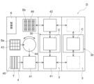
- FIG. 1 is a schematic diagram of a resin molding unit.
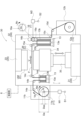
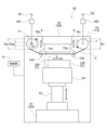
- FIG. 2 is a schematic diagram showing a resin molding apparatus.
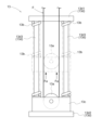
- FIG. 3 is a schematic diagram showing the moving mechanism of the film supply mechanism.
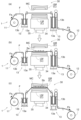
- FIG. 4 is a schematic diagram showing a method of manufacturing a resin molded product.
- FIG. 5 is a control flow diagram of the film transport mechanism.
- FIG. 6 is a schematic diagram showing a resin molding apparatus according to another embodiment.
- the substrate (molding object) on which the semiconductor chip is fixed is used as an electronic component by sealing with resin.
- a compression method compression molding
- a transfer method, and the like can be cited as techniques for resin-sealing an object to be molded.
- the compression methods after supplying liquid resin (resin material) to the release film, the release film is adsorbed to the lower mold of the mold, and the object to be molded is immersed in the liquid resin on the release film.
- a method of resin molding can be mentioned.
- the transfer methods the object to be molded is placed on the release film that is adsorbed to the lower mold of the mold, and a resin tablet (resin material) is supplied to the pot of the mold.
- a method of resin-molding an object to be molded by heating and melting the resin by heating and supplying the molten resin to the cavity can be mentioned.
- Liquid resin includes not only resin that is liquid at normal temperature (room temperature), but also molten resin that is melted by heating and becomes liquid.
- the liquid resin that becomes liquid at room temperature may be either a thermoplastic resin or a thermosetting resin.
- a thermosetting resin is a liquid resin at room temperature, and when heated, its viscosity decreases, and when further heated, it polymerizes and hardens to become a hardened resin. As described below, it is desirable to use a thermosetting resin when resin-molding and sealing the pre-molding substrate to which the semiconductor chip is fixed.
- the powdery resin includes not only powdery resin but also resin tablets formed of solid resin obtained by pressing powdery resin. It becomes a molten resin.
- This powdery resin may be either a thermoplastic resin or a thermosetting resin. When the thermosetting resin is heated, its viscosity decreases, and when it is further heated, it polymerizes and hardens to become a cured resin. As described below, it is desirable to use a thermosetting resin when resin-molding and sealing the pre-molding substrate to which the semiconductor chip is fixed.
- FIG. 1 shows a schematic diagram of a resin molding unit D equipped with a resin molding device 30 according to this embodiment.
- the resin molding unit D includes a molding module 3, a supply module 4, a controller 6, and a transport mechanism.
- the molding module 3 has a resin molding device 30 for resin-sealing an object to be molded.
- the control unit 6 includes at least a program stored in hardware such as an HDD or memory as software for controlling the operation of the resin molding apparatus 30, and includes a computer ASIC, FPGA, CPU, or other hardware processor. Executed by
- the resin molding device 30 in this embodiment is a device for resin-molding the pre-molding substrate Sa to which the semiconductor chip is fixed, and is incorporated in the molding module 3 .
- the molding module 3 may be a resin molding device, and the resin molding unit D may be a resin molding device, without any particular limitation.
- the molding module 3 uses the resin molding device 30 to seal the pre-molding substrate Sa (molding object) with resin to mold the molded substrate Sb (resin molded product).
- a plurality of molding modules 3 are provided, and each molding module 3 can be attached or detached independently. Details of the resin molding apparatus 30 will be described later.
- the supply module 4 is for supplying the pre-molding substrate Sa and the resin tablet T to the molding module 3 and receiving the molded substrate Sb from the molding module 3. It includes a mechanism 45 and a substrate receiving portion 46 .
- a loader 41 and an unloader 42 included in the transport mechanism wait inside the supply module 4 .
- the substrate supply mechanism 43 delivers the stock pre-molded substrates Sa to the substrate alignment mechanism 44 .
- One semiconductor chip or a plurality of semiconductor chips are aligned in the vertical direction and/or the horizontal direction and fixed to the pre-molding substrate Sa.
- the substrate alignment mechanism 44 puts the pre-molding substrate Sa delivered from the substrate supply mechanism 43 into a state suitable for transportation.
- the resin supply mechanism 45 stocks the resin tablets T, and arranges the resin tablets T in a state suitable for transportation.
- the transport mechanism includes a loader 41 that transports the pre-molding substrate Sa to which the semiconductor chip before resin sealing is fixed and the resin tablet T, and an unloader 42 that transports the molded substrate Sb after resin sealing.
- the loader 41 receives the pre-molding substrate Sa from the substrate alignment mechanism 44, receives the resin tablet T from the resin supply mechanism 45, and moves from the supply module 4 to each molding module 3 on the rail.
- the substrate Sa before molding and the resin tablet T can be transferred.
- the unloader 42 can take out the molded substrates Sb from the molding modules 3 , move on the rails from each molding module 3 to the substrate storage section 46 , and store the molded substrates Sb in the substrate storage section 46 .
- the semiconductor chip is sealed with a cured resin obtained by solidifying the molten resin.
- FIG. 2 shows a resin molding device 30 in this embodiment.
- the resin molding apparatus 30 includes a stationary frame 3A placed on a horizontal surface and fixed in an immovable state by gravity, a molding die C supported by the stationary frame 3A, a movable platen 34 supported by the stationary frame 3A, and a movable platen 34.
- a mold clamping mechanism 35 for clamping the mold C by moving the platen 34 and a film supply mechanism 1 for supplying the release film F are provided.
- "supported by the fixed frame 3A” means a state in which the fixed frame 3A is supported directly or indirectly so as to be relatively movable with respect to the fixed frame 3A, and the same applies hereinafter.
- the fixed frame 3A includes a frame main body in which a lower fixed plate 31 and an upper fixed plate 33, which are rectangular in plan view, are connected by a plurality of tie bars (not shown) or plate-like members (not shown). It is configured.
- a movable platen 34 having a rectangular shape in plan view is provided between the lower stationary platen 31 and the upper stationary platen 33 .
- the mold C has an upper mold UM and a lower mold LM.
- the upper mold UM and the lower mold LM are composed of molds and the like arranged to face each other.
- a heater (not shown) is built in the upper mold UM and the lower mold LM, and the substrate and the resin tablet supplied to the molding die C can be heated by the heater.
- the lower mold LM is provided with an adsorption mechanism (not shown) for adsorbing the release film F to the mold surface by means of a vacuum pump or the like.
- the movable platen 34 can move up and down along the tie bars or plate members of the fixed frame 3A, and moves the lower die LM up and down so as to displace the relative positions of the lower die LM and the upper die UM.
- a mold clamping mechanism 35 for moving the movable platen 34 up and down is provided on the lower stationary platen 31 .
- the mold clamping mechanism 35 is composed of, for example, a combination of a servomotor and a ball screw, a combination of a hydraulic cylinder and a link mechanism, or the like.
- the mold clamping mechanism 35 can clamp the mold C by moving the movable platen 34 upward, and can open the mold C by moving the movable platen 34 downward.
- the film supply mechanism 1 supplies the release film F between the upper mold UM and the lower mold LM.
- a resin material having properties such as heat resistance, release properties, flexibility, and extensibility is used. copolymer), PET (polyethylene terephthalate), FEP (tetrafluoroethylene/hexafluoropropylene copolymer), polypropylene, polystyrene, polyvinylidene chloride, and the like.
- the film supply mechanism 1 includes a delivery mechanism 11 that delivers the release film F, a film transport mechanism 7 that transports the release film F, a recovery mechanism 12 that recovers the release film F, and a transport path for the release film F.
- a pair of moving mechanisms 13, 13 arranged on the side of the delivery mechanism 11 (between the mold C and the delivery mechanism 11) and on the side of the collection mechanism 12 (between the mold C and the nip roll 16).
- the film transport mechanism 7 that transports the release film F includes a nip roll 16 .
- the control unit 6 controls the rotation speed Na of the delivery mechanism 11 and the rotation speed Nc of the nip roll 16, so that the release film F is conveyed while applying an appropriate tension to the release film F. be done.
- the delivery mechanism 11 can deliver the release film F before use between the upper mold UM and the lower mold LM, and is fixed to the stationary frame 3A.
- the delivery mechanism 11 in the present embodiment includes a delivery roll 11a that delivers the release film F before use wound on the reel, and a first motor M1 (corresponding to a motor) that rotates the delivery roll 11a. , and a delivery roll 11a are accommodated in an openable and closable case 11b.
- the first motor M1 is provided with a first sensor S1 (corresponding to a sensor) that detects the amount of rotation (rotational position) of the motor shaft (not shown).
- the delivery mechanism 11 including the case 11b is fixed to the side of the fixed frame 3A outside the fixed frame 3A.
- the first motor M1 is composed of a servomotor or the like that can control the rotation position and rotation speed
- the first sensor S1 is an encoder (rotation detector) that detects the amount of rotation of the servomotor or the like according to the number of pulses. consists of
- the "rotation amount” is information indicating how many times the motor shaft has moved, and in the case of 360 degrees, it is one rotation (the same applies hereinafter).
- the recovery mechanism 12 can recover the used release film F used for resin molding, and is fixed to the fixed frame 3A.
- the recovery mechanism 12 in this embodiment includes a recovery roll 12a that winds and recovers the used release film F on a reel, and a motor (not shown) that rotates the recovery roll 12a. are housed in an openable and closable case 12b.
- the recovery mechanism 12 including the case 12b is fixed outside the fixed frame 3A on the side of the fixed frame 3A opposite to the delivery mechanism 11. As shown in FIG.
- a plurality of (four in this embodiment) delivery rollers 14a to 14d are rotatably fixed to the fixed frame 3A.
- the plurality of delivery rollers 14a to 14d includes a first delivery roller 14a and a second delivery roller 14b arranged in order from the delivery mechanism 11 side between the delivery mechanism 11 and the moving mechanism 13, the moving mechanism 13, and the mold C.
- a pair of delivery rollers 14c and 14d located closest to the mold C sandwich the release film F and guide the release film F so as to be parallel to the surface of the mold C. As shown in FIG.
- a plurality of (four in this embodiment) collecting rollers 15a to 15d are rotatably fixed to the fixed frame 3A.
- a plurality of recovery rollers 15a to 15d are arranged between the moving mechanism 13 and the molding die C, a first upper recovery roller 15a and a second lower recovery roller 15b, and between the moving mechanism 13 and the recovery mechanism 12. and a third collection roller 15c and a fourth collection roller 15d arranged in order from the nip roll 16 side.
- a pair of recovery rollers 15a and 15b positioned closest to the mold C sandwich the release film F and guide the release film F so as to be parallel to the mold surface of the mold C. As shown in FIG.
- the moving mechanism 13 has a moving roller 13a that applies an appropriate tension to the release film F by moving in conjunction with the displacement of the relative positions of the upper die UM and the lower die LM.
- the moving roller 13a is supported by the stationary frame 3A.
- the sending mechanism 11, the collecting mechanism 12, the sending rollers 14a to 14d, and the collecting rollers 15a to 15d are fixed to the fixed frame 3A, the moving roller 13a moves in conjunction with the vertical movement of the lower die LM.
- Appropriate tension can be applied to the release film F by moving up and down. Details of the moving mechanism 13 will be described later.
- the film transport mechanism 7 includes a nip roll 16 that presses and holds the release film F, and a second motor M2 that rotates the transport roller 16a of the nip roll 16.
- the second motor M2 has a motor shaft
- a second sensor S2 is provided to detect the amount of rotation (rotational position) (not shown).
- the nip roll 16 is rotatably fixed to the fixed frame 3A on the recovery mechanism 12 side (between the moving mechanism 13 on the recovery mechanism 12 side and the recovery mechanism 12) in the transport path of the release film F.
- the nip roll 16 includes a conveying roller 16a that is rotated by the driving force of the second motor M2 to adjust the conveying speed V of the release film F, and a pressing roller 16b that presses the release film F toward the conveying roller 16a. I'm in.
- the surfaces of the conveying roller 16a and the pressing roller 16b are covered with rubber, resin, or the like having a high coefficient of friction in order to hold the release film F thereon.
- the second motor M2 is composed of a servomotor or the like that can control the rotational position and rotational speed
- the second sensor S2 is an encoder (rotation detector) that detects the amount of rotation of the servomotor or the like according to the number of pulses. consists of
- the operation of the film supply mechanism 1 is controlled by the controller 6.
- the controller 6 rotates the delivery roll 11a of the delivery mechanism 11 in the same direction as the direction in which the film transport mechanism 7 transports the release film F.
- “rotate the delivery roll 11a in the same direction as the direction in which the release film F is conveyed” means that the rotation tangential direction at the delivery point of the delivery roll 11a where the release film F is delivered from the delivery roll 11a is the release film F. It refers to rotating the delivery roll 11a so that the film F is transported.
- the control unit 6 controls the transport speed V of the release film F by controlling the rotational speed Nc of the transport roller 16a of the nip roll 16. Further, when the transport roller 16a transports the release film F, the control unit 6 controls the rotation speed of the delivery roll 11a around which the release film F is wound so that the film width of the release film F is within the allowable range. By controlling Na, the tension applied to the release film F becomes moderate. Specifically, the control unit 6 sends the release film F so that the difference between the transport speed V of the release film F by the film transport mechanism 7 and the delivery speed Va of the release film F by the delivery mechanism 11 becomes a predetermined speed difference. The rotation speed Na of the roll 11a is controlled.
- the controller 6 adjusts the value of the difference (V ⁇ Va) between the conveying speed V and the conveying speed Va so that the conveying speed Va of the release film F is slightly lower than the conveying speed V of the release film F.
- the transport speed V of the release film F is a predetermined set value. ). Further, the delivery speed Va of the release film F is calculated by the formula (2) by multiplying the rotational speed Na of the delivery roll 11a by the circumferential length (diameter Da ⁇ ) of the delivery roll 11a.
- the rotation speed Nc of the conveying roller 16a is obtained by dividing the output value (rotation amount) of the second sensor S2 by time and the second reduction ratio (the number of rotations of the second motor M2 when the conveying roller 16a rotates once). , the diameter Dc of the conveying roller 16a remains unchanged.
- the control unit 6 controls the rotation speed Nc of the transport roller 16a to a constant speed based on the output value of the second sensor S2 so that the transport speed V becomes the set value.
- the rotation speed Na of the delivery roll 11a is obtained by dividing the output value (rotation amount) of the first sensor S1 by time and the first reduction ratio (the number of revolutions of the first motor M1 when the delivery roll 11a rotates once). If the diameter Da of the delivery roll 11a, which changes according to the delivery amount of the release film F, is known, the delivery speed Va can be calculated.
- the control unit 6 controls the rotation speed Na of the delivery roll 11a, the control unit 6 adjusts the rotation speed Na of the delivery roll 11a according to the diameter (diameter Da) of the delivery roll 11a around which the release film F is wound. change.
- the diameter Da of the delivery roll 11a is proportional to the actual amount of rotation of the delivery roll 11a with respect to one transport amount of the release film F, and the output value Ra of the first sensor S1 and the release film
- the value multiplied by the diameter (diameter Das) of the delivery roll 11a without the release film F wound thereon is calculated as the hypothetical delivery roll 11a without the release film F wound with respect to one conveying amount of the release film F. It can be obtained by dividing by the output value Ras of the first sensor S1, which is proportional to the amount of rotation.
- the amount of one conveying of the release film F is a set value.
- the diameter (diameter Das) of the delivery roll 11a in a state where the release film F is not wound is a constant value
- the output value Ra of the first sensor S1 can be measured
- the output value Ras of the first sensor S1 is Since it is a default value corresponding to the transport amount of the release film F
- the diameter Da of the delivery roll 11a can be calculated.
- the transport amount of the release film F is the value obtained by dividing the output value of the second sensor S2 by the second reduction ratio, and the peripheral length of the transport roller 16a (diameter Dc ⁇ ) may be calculated.
- the diameter Da of the delivery roll 11a is the conveying amount La (mm) of the release film F when the output value Ra of the first sensor S1 becomes a predetermined value (for example, one rotation), as shown in Equation (4). and the diameter (diameter Das) of the delivery roll 11a in which the release film F is not wound is the same as the above. It may be obtained by dividing by the conveying amount Las (mm) of the release film F when it becomes a predetermined value (one rotation).
- the conveying amount La of the release film F is a predetermined conveying speed V (set value) or a conveying speed V obtained based on the above-described formula (1), and the output value Ra of the first sensor S1 is a predetermined value. can be calculated over time.
- the transport amount La of the release film F is a set value proportional to the time when the output value Ra of the first sensor S1 becomes a predetermined value, or the time when the output value Ra of the first sensor S1 becomes a predetermined value. It can be calculated by multiplying the value obtained by dividing the corresponding output value of the second sensor S2 by the second speed reduction ratio by the circumferential length (diameter Dc ⁇ ) of the conveying roller 16a.
- the diameter (diameter Das) of the delivery roll 11a in which the release film F is not wound is a constant value, and the output value Ra of the first sensor S1 and the output value Rc of the second sensor S2 are measurable, Since the transport amount Las of the release film F when the rotation amount of the delivery roll 11a reaches a predetermined value (for example, one rotation) is a default value, the diameter Da of the delivery roll 11a can be calculated.
- the diameter Da of the delivery roll 11a is determined by the predetermined conveying speed V (set value) or the conveying speed V obtained based on the above-described formula (1), as shown in Equation (5).
- the transport amount Lf of the release film F calculated by the above is approximate to the transport amount of the release film F delivered by the transport roll 11a
- the transport amount Lf is divided by the output value Ra of the first sensor S1. Then, it can be estimated by multiplying by the first speed reduction ratio.
- the smaller the difference between the conveying speed V of the release film F by the film conveying mechanism 7 by the feeding mechanism 11 and the feeding speed Va of the release film F the higher the estimation accuracy.
- the controller 6 controls the delivery roll 11a so that the difference between the transport speed V of the release film F by the film transport mechanism 7 and the delivery speed Va of the release film F by the delivery mechanism 11 becomes a predetermined speed difference. can be accurately changed in real time.
- the moving mechanisms 13 provided on the sending mechanism 11 side and the collecting mechanism 12 side respectively hold the moving roller 13a, the spring 13b that presses the moving roller 13a, and the moving roller 13a. and a support frame 13d for supporting the moving roller 13a, the spring 13b and the holding plate 13c.
- the pair of moving rollers 13a, 13a are fixed to a holding plate 13c on the delivery mechanism 11 side and the collection mechanism 12 side in the transport path of the release film F, and are supported by the fixed frame 3A via the support frame 13d. there is The moving roller 13a can move up and down in conjunction with the relative movement (vertical movement) of the lower mold LM with respect to the upper mold UM by the mold clamping mechanism 35 .
- the spring 13b is composed of a compression spring or the like, and presses the moving roller 13a via the holding plate 13c in the direction of applying tension to the release film F (downward).
- the pressing force of the spring 13b is larger than the tension applied to the release film F, and the force with which the delivery mechanism 11 and the recovery mechanism 12 hold the release film F (the force applied to the delivery roll 11a and the recovery roll 12a in the stationary state). It is set smaller than the value obtained by dividing the radius by the rotational torque applied.
- the "pressing force of the spring 13b" means the force applied to the moving roller 13a by the pressing force of the spring 13b.
- the holding plate 13c rotatably holds the moving roller 13a and is supported by the support frame 13d.
- the support frame 13d is fixed to the fixed frame 3A, and is formed by connecting four corners of an upper plate 13d1 and a lower plate 13d2 with a plurality of (four in this embodiment) rod-shaped members 13d3.
- the holding plate 13c is provided with a hole through which the rod-shaped member 13d3 passes, and can move up and down along the rod-shaped member 13d3.
- the spring 13b is arranged outside the rod-like member 13d3, and has one end in contact with the lower surface of the upper plate 13d1 and the other end in contact with the upper surface of the holding plate 13c.
- a method for manufacturing a resin molded product includes a film supply step of supplying a release film F between an upper mold UM and a lower mold LM by a film supply mechanism 1, and a mold C by a mold clamping mechanism 35. and a molding step of supplying the pre-molding substrate Sa and a resin material (resin obtained by melting the resin tablet T) to the molding die C to perform resin molding.
- the film supply mechanism 1 conveys the release film F
- the film supply mechanism 1 rotates the delivery roll 11a in the same direction as the direction in which the release film F is conveyed.
- the control unit 6 controls the rotation speed Na of the delivery roll 11a around which the release film F is wound so that the film width of the release film F is within the allowable range.
- the loader 41 is heated in advance while the housing space for the resin tablet T is insulated, and the molding die C is also heated. Then, the pre-molded substrate Sa taken out from the substrate supply mechanism 43 is placed on the loader 41 . Also, the resin tablets T aligned by the resin supply mechanism 45 are stored in the resin tablet T storage space of the loader 41 . Then, the loader 41 conveys the pre-molding substrate Sa and the resin tablet T to the molding module 3, and stores the resin tablet T in the pot of the lower mold LM. By housing the resin tablet T in the pot, the heater incorporated in the lower mold LM heats the resin tablet T to become a molten resin.
- the film supply mechanism 1 supplies the release film F before use between the upper mold UM and the lower mold LM (FIG. 4(a), film supply process).
- the operation of the film supply mechanism 1 is controlled as shown in FIG. 5 using the resin molding apparatus 30 shown in FIG.
- the controller 6 determines that the transfer speed V is set to the set value.
- the rotational speed Nc of the conveying roller 16a is controlled to a constant speed (#52 in FIG. 5).
- the control unit 6 controls a predetermined driving condition (for example, the rotational speed Na of the delivery roll 11a before exchanging the release film F, or the predetermined rotational speed Na of the delivery roll 11a).
- the first motor M1 is controlled to rotate the conveying roller 16a of the nip roll 16 and the delivery roll 11a of the delivery mechanism 11 in the same direction (#53 in FIG. 5).
- the control unit 6 stops the rotation of the delivery roll 11a and the rotation of the transport roller 16a and the collection roll 12a (#54 in FIG. 5).
- control unit 6 adjusts the diameter of the delivery roll 11a to the output of the first sensor S1 when the delivery roll 11a is rotationally driven under the predetermined drive conditions according to the above equation (3) or (4). It is calculated based on the value and the diameter of the delivery roll 11a in a state where the release film F is not wound (#55 in FIG. 5). In addition, the control unit 6 calculates the feeding speed Va of the release film F at which the value of the difference (V ⁇ Va) between the conveying speed V (set value) and the feeding speed Va becomes a predetermined speed difference (see FIG. 5 #56).
- a feeding speed Va of the release film F is calculated. 5, the diameter of the delivery roll 11a when the release film F is replaced can be determined, and the delivery speed Va of the release film F at the next film transport time can be determined. Can be set.
- the control unit 6 controls the first motor M1 and the second motor M2 to rotationally drive the conveying roller 16a of the nip roll 16 and the delivery roll 11a of the delivery mechanism 11 in the same direction (#57, #58 in FIG. 5). ).
- the controller 6 controls the rotational speed Nc of the conveying roller 16a to be constant based on the output value of the second sensor S2 so that the conveying speed V becomes the set value.
- the delivery roll 11a is rotated in the same direction as the direction in which the film transport mechanism 7 transports the release film F. Therefore, compared to the case where the delivery roll 11a is rotated in the direction opposite to the direction in which the release film F is conveyed, it is possible to prevent the film width from shrinking due to excessive tension Fa being applied to the release film F. As a result, when the mold clamping mechanism 35 is operated, the shape of the release film F becomes appropriate, and the molding accuracy is improved. None.
- control unit 6 controls the release film F so that the difference between the transport speed V of the release film F by the film transport mechanism 7 and the delivery speed Va of the release film F by the delivery mechanism 11 becomes a predetermined speed difference.
- the rotation speed Na of the delivery roll 11a is controlled while changing the rotation speed Na of the delivery roll 11a according to the diameter of the wound delivery roll 11a (#59 in FIG. 5). That is, based on the diameter of the delivery roll 11a and the delivery speed Va calculated in #55 to #56 in FIG. 5 and #62 to #63 in FIG. Control the rotational speed Na.
- the control unit 6 stops the rotation of the delivery roll 11a, stops the rotation of the conveyance roller 16a and the collection roll 12a, and reduces the tension applied to the release film F. Fa and Fb are maintained (#60 in FIG. 5). Although detailed description is omitted, in the film supply process, the control unit 6 also controls the operation of the recovery mechanism 12 to recover the release film F while applying a predetermined tension to the release film F. do.
- the rotation speed of the delivery roll 11a is adjusted according to the diameter of the delivery roll 11a around which the release film F is wound so that the difference between the transport speed V and the delivery speed Va of the release film F becomes a predetermined speed difference.
- the tension Fa of the release film F can be kept constant even if the winding amount of the release film F on the delivery roll 11a fluctuates. As a result, it is possible to prevent the problem that the tension Fa is excessively applied to the release film F and the film width shrinks.
- the mold clamping process which will be described later, is performed.
- the controller 6 sets the diameter of the delivery roll 11a to It is calculated based on the output value of the first sensor S1 at the time of the previous film transport and the diameter of the delivery roll 11a in the state where the release film F is not wound (#62 in FIG. 5).
- the control unit 6 calculates the feeding speed Va of the release film F at which the value of the difference (V ⁇ Va) between the conveying speed V (set value) and the feeding speed Va becomes a predetermined speed difference (see FIG. 5 #63).
- a feeding speed Va of the release film F is calculated.
- steps #57 to #60 in FIG. 5 are repeated to control the rotational speed Na of the delivery roll 11a.
- the controller 6 may calculate the diameter of the delivery roll 11a and the delivery speed Va of the release film F in real time while the release film F is being transported.
- the amount of movement of the lower mold LM when the release film F before use is brought into close contact with the lower mold LM is sufficient if there is a space between the upper mold UM and the lower mold LM that can supply the pre-molding substrate Sa. preset.
- the mold clamping mechanism 35 moves the movable platen 34 further upward to move the upper mold UM and the lower mold LM closer to each other, thereby clamping the mold C (Fig. 4(c), mold clamping step).
- the spring 13b resists the tension Fa of the release film F, and the state shown in FIG.
- the pair of moving rollers 13a, 13a moves upward, and the tension Fa applied to the release film F becomes appropriate.
- the pressing force of the spring 13b is set larger than the tension Fa applied to the release film F and smaller than the force with which the release film F is held by the delivery mechanism 11 and the recovery mechanism 12.
- the used release film F is removed from the mold C by driving the transport roller 16a, and the release film F before use is removed.
- a film supply step is performed to supply the film to the mold C, and this film supply step, the mold clamping step and the molding step described above are repeatedly performed.
- the release film F runs short on the delivery roll 11a of the delivery mechanism 11, or when the recovery roll 12a of the recovery mechanism 12 can no longer take up the release film F, the cases 11b and 12b are removed. It is opened to replace the delivery roll 11a or the collection roll 12a (see also FIG. 2).
- the feeding mechanism 11 and the collecting mechanism 12 are fixed to both sides of the fixed frame 3A, it is possible to replace the release film F outside the fixed frame 3A. Easy to replace F. Further, by providing the delivery mechanism 11 and the recovery mechanism 12 outside the fixed frame 3A, it is easy to secure the installation space for the delivery mechanism 11 and the recovery mechanism 12. Therefore, according to the required amount of the release film F, the delivery mechanism 11 And the size of the recovery mechanism 12 can be changed, which is highly convenient.
- FIG. 6 shows a resin molding device 30 according to another embodiment.
- the release film F is attached to the lower mold LM, but in the present embodiment, the release film F is attached to the upper mold UM.
- the upper die UM is provided with a suction mechanism (not shown) that causes the release film F to be attracted to the mold surface by a vacuum pump or the like.
- the resin molding apparatus 30 includes a fixed frame 3A, a mold C supported by the fixed frame 3A, a movable platen 34 supported by the fixed frame 3A, and a mold for clamping the mold C by moving the movable platen 34.
- a tightening mechanism 35 and a film supply mechanism 1 for supplying the release film F are provided.
- the resin molding apparatus 30 in this embodiment does not include the moving mechanism 13 described above, but includes a vertical moving mechanism 8 that simultaneously moves the feeding mechanism 11 and the film conveying mechanism 7 vertically.
- the vertical movement mechanism 8 vertically moves a movable member (not shown) supported by the fixed frame 3A using a driving force such as a motor or an air cylinder (not shown).
- This movable member is connected to the delivery mechanism 11 and the film transport mechanism 7, and the vertical movement mechanism 8 moves the delivery mechanism 11 and the film transport mechanism 7 up and down at the same time.
- the film transport mechanism 7 is composed of the nip roll 16 and the recovery mechanism 12 described above.
- the vertical movement mechanism 8 raises the delivery mechanism 11 and the film transport mechanism 7 to supply the release film F to the upper mold UM before the mold clamping mechanism 35 raises the lower mold LM.
- the vertical movement mechanism 8 is provided to raise the feeding mechanism 11 and the film conveying mechanism 7 before the mold clamping mechanism 35 lifts the lower mold LM, when the mold clamping mechanism 35 is activated, the moving roller 13a The tension of the release film F becomes moderate. Since the operation mode of the film transport mechanism 7 is the same as that of the above-described embodiment, description thereof is omitted.
- the sending mechanism 11 and the collecting mechanism 12 are fixed on both sides of the fixed frame 3A, but the sending mechanism 11 and the collecting mechanism 12 may be fixed inside the fixed frame 3A.
- the moving roller 13a is pressed by the spring 13b, but the moving roller 13a may be pressed by the fluid supplied to the cylinder.
- the pressing force against the moving roller 13a may be changed in conjunction with the relative movement of the lower die LM and the upper die UM.
- a moving roller 13a may be further provided.
- the delivery mechanism 11 in the above-described embodiment may have any structure as long as it is a mechanism capable of delivering the release film F.
- the recovery mechanism 12 in the above-described embodiment may have any structure as long as it is a mechanism capable of recovering the release film F.
- a mechanism may be provided to hold the release film F and apply an appropriate tension so that the release film F does not move on the side.
- the transfer-type resin molding apparatus 30 has been described, but the compression-type resin molding apparatus 30 can also be applied.
- Substrates resin-molded by the resin molding apparatus 30 are, for example, semiconductor substrates (silicon wafers, etc.), metal substrates (lead frames, etc.), glass substrates, ceramic substrates, resin substrates, or wiring substrates.
- the characteristic configuration of the resin molding apparatus 30 includes a mold C having an upper mold UM and a lower mold LM, a mold clamping mechanism 35 for clamping the mold C, and a space between the upper mold UM and the lower mold LM. and a film feeding mechanism 1 having a feeding mechanism 11 including a feeding roll 11a for feeding the release film F and a film conveying mechanism 7 for conveying the release film F, and the operation of the film feeding mechanism 1.
- the control unit 6 moves the delivery roll 11a in the same direction as the direction in which the film transport mechanism 7 transports the release film F. The point is to rotate the
- the delivery roll 11a is rotated in the same direction as the direction in which the film transport mechanism 7 transports the release film F. Therefore, compared to the case where the delivery roll 11a is rotated in the direction opposite to the direction in which the release film F is conveyed, it is possible to prevent the inconvenience of shrinking the film width due to excessive tension applied to the release film F. As a result, when the mold clamping mechanism 35 is operated, the shape of the release film F becomes appropriate, and the molding accuracy is improved. None. In this manner, the resin molding apparatus 30 can transport the release film F while maintaining its shape.
- the control unit 6 controls the release film F so that the difference between the transport speed V of the release film F by the film transport mechanism 7 and the delivery speed Va of the release film F by the delivery mechanism 11 becomes a predetermined speed difference.
- the rotation speed Na of the delivery roll 11a may be changed according to the diameter of the delivery roll 11a around which the film is wound.
- the rotation speed of the delivery roll 11a is adjusted according to the diameter of the delivery roll 11a around which the release film F is wound so that the difference between the transport speed V and the delivery speed Va of the release film F becomes a predetermined speed difference.
- the tension of the release film F can be kept constant even if the winding amount of the release film F on the delivery roll 11a fluctuates. As a result, it is possible to prevent the inconvenience of shrinking the film width due to excessive tension being applied to the release film F.
- the controller 6 may calculate the diameter of the delivery roll 11a wound with the release film F based on the diameter of the delivery roll 11a without the release film F wound thereon.
- the diameter of the delivery roll 11a in which the release film F is not wound does not change, based on this diameter, the diameter of the delivery roll 11a around which the release film F is wound can be calculated. It simplifies the process.
- the delivery mechanism 11 includes a motor (first motor M1) that rotates the delivery roll 11a, and a sensor (first sensor S1) that detects the amount of rotation of the first motor M1.
- 6 is the diameter of the delivery roll 11a wound with the release film F, which is the product of the output value of the first sensor S1 and the diameter of the delivery roll 11a in the state where the release film F is not wound. It may be obtained by dividing the transport amount of the film F by the output value of the first sensor S1 in the delivery roll 11a in which the release film F is not wound.
- the diameter of the delivery roll 11a around which the release film F is wound is obtained in this way, the calculation speed is increased, so the rotational speed of the delivery roll 11a can be controlled in real time.
- the delivery mechanism 11 includes a motor (first motor M1) that rotates the delivery roll 11a, and a sensor (first sensor S1) that detects the amount of rotation of the first motor M1.
- 6 represents the diameter of the delivery roll 11a around which the release film F is wound, the transport amount of the release film F when the output value of the first sensor S1 reaches a predetermined value, and the release film F not wound. It is obtained by dividing the product of the diameter of the delivery roll 11a in the state and the transport amount of the release film F when the rotation amount of the delivery roll 11a in the state where the release film F is not wound reaches a predetermined value. can be
- the diameter of the delivery roll 11a around which the release film F is wound is obtained in this way, the calculation speed is increased, so the rotational speed of the delivery roll 11a can be controlled in real time.
- a pair of moving rollers 13a that move in conjunction with the displacement of the relative position with respect to the mold LM may be further provided.
- the moving roller 13a may be pressed in a direction in which tension is applied to the release film F by a spring 13b.
- the tension applied to the release film F can be moderated without providing a complicated control mechanism.
- the feeding mechanism 11 and the film conveying mechanism 7 may be raised to supply the release film F to the upper mold UM.
- the vertical movement mechanism 8 is provided to raise the feeding mechanism 11 and the film conveying mechanism 7 before the mold clamping mechanism 35 lifts the lower mold LM, when the mold clamping mechanism 35 is activated, the moving roller 13a The tension of the release film F becomes moderate.
- the method of manufacturing a resin molded product (molded substrate Sb) using the resin molding apparatus 30 described in any one of (1) to (9) is characterized in that the upper die UM and the lower die LM are formed by the film supply mechanism 1.
- the delivery roll 11a is rotated in the same direction as the direction.
- the film transport mechanism 7 rotates the delivery roll 11a in the same direction as the release film F is transported, so that the film width can be prevented from shrinking.
- the mold clamping mechanism 35 is operated, the shape of the release film F becomes appropriate, and the molding accuracy is improved. None.
- the resin molding method enables the release film F to be transported while maintaining its shape.
- the present disclosure can be used for a resin molding apparatus and a method for manufacturing a resin molded product.
- Reference Signs List 1 Film supply mechanism 3A: Fixed frame 6: Control unit 7: Film transport mechanism 8: Vertical movement mechanism 11: Sending mechanism 11a: Sending roll 13: Moving mechanism 13a: Moving roller 13b: Spring 30: Resin molding device 35: Mold Tightening mechanism C: Mold Da: Diameter (diameter of delivery roll around which release film is wound) Das: diameter (diameter of delivery roll without release film wound) F: release film LM: lower mold M1: first motor (motor) Na: Rotation speed S1: First sensor (sensor) Sa: Substrate before molding UM: Upper die V: Conveyance speed Va: Delivery speed
Landscapes
- Engineering & Computer Science (AREA)
- Mechanical Engineering (AREA)
- Manufacturing & Machinery (AREA)
- Robotics (AREA)
- Moulds For Moulding Plastics Or The Like (AREA)
- Processing And Handling Of Plastics And Other Materials For Molding In General (AREA)
- Injection Moulding Of Plastics Or The Like (AREA)
- Casting Or Compression Moulding Of Plastics Or The Like (AREA)
Abstract
Description
図2は、樹脂成形装置を示す模式図である。
図3は、フィルム供給機構の移動機構を示す模式図である。
図4は、樹脂成形品の製造方法を示す模式図である。
図5は、フィルム搬送機構の制御フロー図である。
図6は、別実施形態における樹脂成形装置を示す模式図である。
以下、トランスファ方式の樹脂成形装置を一例として説明する。図1には、本実施形態における樹脂成形装置30を備えた樹脂成形ユニットDの模式図が示されている。樹脂成形ユニットDは、成形モジュール3と供給モジュール4と制御部6と搬送機構とを備えている。成形モジュール3は、成形対象物を樹脂封止するための樹脂成形装置30を有している。制御部6は、少なくとも樹脂成形装置30の作動を制御するソフトウェアとして、HDDやメモリ等のハードウェアに記憶されたプログラムを含んでおり、コンピュータのASIC,FPGA,CPU又は他のハードウェアを含むプロセッサにより実行される。
図2には、本実施形態における樹脂成形装置30が示されている。樹脂成形装置30は、水平面に載置されて重力により不動状態で固定された固定フレーム3Aと、固定フレーム3Aに支持された成形型Cと、固定フレーム3Aに支持された可動プラテン34と、可動プラテン34を移動させて成形型Cを型締めする型締め機構35と、離型フィルムFを供給するフィルム供給機構1と、を備えている。なお、「固定フレーム3Aに支持される」とは、固定フレーム3Aに対して相対移動可能に固定フレーム3Aにて直接的又は間接的に支えられている状態を意味し、以下同様である。




図1~図2及び図4~図5を用いて、樹脂成形品の製造方法を説明する。樹脂成形品(成形済基板Sb)の製造方法は、フィルム供給機構1により上型UMと下型LMとの間に離型フィルムFを供給するフィルム供給工程と、型締め機構35により成形型Cを型締めする型締め工程と、成形型Cに成形前基板Sa及び樹脂材料(樹脂タブレットTを溶融させた樹脂)を供給して樹脂成形を行う成形工程と、を含んでいる。フィルム供給工程は、フィルム供給機構1が離型フィルムFを搬送するとき、フィルム供給機構1が離型フィルムFを搬送する方向と同じ方向に送出ロール11aを回転させる。このとき、制御部6は、離型フィルムFのフィルム幅が許容範囲内となるように、離型フィルムFが巻かれた送出ロール11aの回転速度Naを制御する。
その結果、第二送出ローラ14bより送出ロール11a側と、搬送ローラ16aより回収ロール12a側とでは、離型フィルムFがほとんど移動しない。よって、離型フィルムFの搬送ラインがずれるといった不都合がない。
図6には、別実施形態に係る樹脂成形装置30が示されている。上述した実施形態では、下型LMに離型フィルムFを吸着させたが、本実施形態では、上型UMに離型フィルムFを吸着させる。つまり、上型UMには、離型フィルムFを真空ポンプ等により型面に吸着させる吸着機構(不図示)が設けられている。
以下、上述の実施形態において説明した樹脂成形装置30及び樹脂成形品の製造方法の概要について説明する。
3A :固定フレーム
6 :制御部
7 :フィルム搬送機構
8 :上下移動機構
11 :送出機構
11a :送出ロール
13 :移動機構
13a :移動ローラ
13b :スプリング
30 :樹脂成形装置
35 :型締め機構
C :成形型
Da :直径(離型フィルムが巻かれた送出ロールの径)
Das :直径(離型フィルムが巻かれていない状態の送出ロールの径)
F :離型フィルム
LM :下型
M1 :第一モータ(モータ)
Na :回転速度
S1 :第一センサ(センサ)
Sa :成形前基板
UM :上型
V :搬送速度
Va :送出速度
Claims (10)
- 上型と下型とを有する成形型と、
前記成形型を型締めする型締め機構と、
前記上型と前記下型との間に離型フィルムを供給し、前記離型フィルムを送り出す送出ロールを含む送出機構と前記離型フィルムを搬送するフィルム搬送機構とを有するフィルム供給機構と、
前記フィルム供給機構の作動を制御する制御部と、を備え、
前記制御部は、前記フィルム搬送機構が前記離型フィルムを搬送するとき、前記フィルム搬送機構が前記離型フィルムを搬送する方向と同じ方向に前記送出ロールを回転させる樹脂成形装置。 - 前記制御部は、前記フィルム搬送機構による前記離型フィルムの搬送速度と前記送出機構による前記離型フィルムの送出速度との差が所定の速度差になるよう、前記離型フィルムが巻かれた前記送出ロールの径に応じて前記送出ロールの回転速度を変化させる請求項1に記載の樹脂成形装置。
- 前記制御部は、前記離型フィルムが巻かれた前記送出ロールの径を、前記離型フィルムが巻かれていない状態の前記送出ロールの径に基づいて算出する請求項2に記載の樹脂成形装置。
- 前記送出機構は、前記送出ロールを回転駆動させるモータと、当該モータの回転量を検出するセンサと、を含んでおり、
前記制御部は、前記離型フィルムが巻かれた前記送出ロールの径を、前記センサの出力値と前記離型フィルムが巻かれていない状態の前記送出ロールの径との乗算値を、前記離型フィルムの搬送量に対する前記離型フィルムが巻かれていない状態の前記送出ロールにおける前記センサの出力値で除算して求める請求項3に記載の樹脂成形装置。 - 前記送出機構は、前記送出ロールを回転駆動させるモータと、当該モータの回転量を検出するセンサと、を含んでおり、
前記制御部は、前記離型フィルムが巻かれた前記送出ロールの径を、前記センサの出力値が所定値となるときの前記離型フィルムの搬送量と、前記離型フィルムが巻かれていない状態の前記送出ロールの径と、の乗算値を、前記離型フィルムが巻かれていない状態の前記送出ロールの回転量が前記所定値となるときの前記離型フィルムの搬送量で除算して求める請求項3に記載の樹脂成形装置。 - 前記成形型を支持する固定フレームと、
前記離型フィルムの搬送経路における前記送出機構側及び前記フィルム搬送機構側で前記固定フレームに支持され、前記型締め機構が前記上型と前記下型との相対位置を変位させるとき、当該相対位置の変位に連動して移動する一対の移動ローラと、を更に備えた請求項1から5のいずれか一項に記載の樹脂成形装置。 - 前記移動ローラは、スプリングにより前記離型フィルムに張力を付与する方向に押圧されている請求項6に記載の樹脂成形装置。
- 前記スプリングの押圧力は、前記離型フィルムに付与される張力よりも大きく、前記送出機構が前記離型フィルムを保持する力よりも小さく設定されている請求項7に記載の樹脂成形装置。
- 前記成形型を支持する固定フレームと、
前記固定フレームに支持され、前記送出機構及び前記フィルム搬送機構を同時に上下移動させる上下移動機構と、を更に備え、
前記上下移動機構は、前記型締め機構が前記下型を上昇させる前に、前記送出機構及び前記フィルム搬送機構を上昇させて、前記上型に前記離型フィルムを供給する請求項1から5のいずれか一項に記載の樹脂成形装置。 - 請求項1から9のいずれか一項に記載の樹脂成形装置を用いた樹脂成形品の製造方法であって、
前記フィルム供給機構により前記上型と前記下型との間に前記離型フィルムを供給するフィルム供給工程と、
前記型締め機構により前記成形型を型締めする型締め工程と、
前記成形型に成形前基板及び樹脂材料を供給して樹脂成形を行う成形工程と、を含み、
前記フィルム供給工程では、前記フィルム搬送機構が前記離型フィルムを搬送するとき、前記フィルム搬送機構が前記離型フィルムを搬送する方向と同じ方向に前記送出ロールを回転させる樹脂成形品の製造方法。
Priority Applications (2)
| Application Number | Priority Date | Filing Date | Title |
|---|---|---|---|
| CN202280079862.0A CN118339003A (zh) | 2021-12-01 | 2022-08-19 | 树脂成型装置以及树脂成型品的制造方法 |
| KR1020247018285A KR20240096628A (ko) | 2021-12-01 | 2022-08-19 | 수지 성형 장치 및 수지 성형품의 제조 방법 |
Applications Claiming Priority (2)
| Application Number | Priority Date | Filing Date | Title |
|---|---|---|---|
| JP2021195155A JP7230160B1 (ja) | 2021-12-01 | 2021-12-01 | 樹脂成形装置及び樹脂成形品の製造方法 |
| JP2021-195155 | 2021-12-01 |
Publications (1)
| Publication Number | Publication Date |
|---|---|
| WO2023100423A1 true WO2023100423A1 (ja) | 2023-06-08 |
Family
ID=85330594
Family Applications (1)
| Application Number | Title | Priority Date | Filing Date |
|---|---|---|---|
| PCT/JP2022/031382 Ceased WO2023100423A1 (ja) | 2021-12-01 | 2022-08-19 | 樹脂成形装置及び樹脂成形品の製造方法 |
Country Status (5)
| Country | Link |
|---|---|
| JP (1) | JP7230160B1 (ja) |
| KR (1) | KR20240096628A (ja) |
| CN (1) | CN118339003A (ja) |
| TW (1) | TWI850821B (ja) |
| WO (1) | WO2023100423A1 (ja) |
Families Citing this family (1)
| Publication number | Priority date | Publication date | Assignee | Title |
|---|---|---|---|---|
| JP2025049905A (ja) * | 2023-09-22 | 2025-04-04 | アピックヤマダ株式会社 | 圧縮成形装置及び圧縮成形方法 |
Citations (6)
| Publication number | Priority date | Publication date | Assignee | Title |
|---|---|---|---|---|
| JP2003174049A (ja) * | 2001-12-04 | 2003-06-20 | Sainekkusu:Kk | 樹脂封止装置 |
| JP2007250681A (ja) * | 2006-03-14 | 2007-09-27 | Matsushita Electric Ind Co Ltd | 半導体樹脂封止装置及びリリースフィルムの供給方法 |
| JP2008188798A (ja) * | 2007-02-01 | 2008-08-21 | Apic Yamada Corp | フィルム搬送装置 |
| JP2016100375A (ja) * | 2014-11-19 | 2016-05-30 | アピックヤマダ株式会社 | 樹脂モールド装置 |
| JP2017183443A (ja) * | 2016-03-30 | 2017-10-05 | Towa株式会社 | 樹脂成形装置、樹脂成形方法、フィルム搬送用ローラ及び樹脂成形装置用フィルム供給装置 |
| JP2021014017A (ja) * | 2019-07-10 | 2021-02-12 | Towa株式会社 | 樹脂成形装置、及び樹脂成形品の製造方法 |
Family Cites Families (7)
| Publication number | Priority date | Publication date | Assignee | Title |
|---|---|---|---|---|
| WO2009113453A1 (ja) * | 2008-03-14 | 2009-09-17 | 東レ株式会社 | 表面に微細な凹凸パターンを有するフィルムの製造方法および製造装置 |
| CN101423153B (zh) * | 2008-11-27 | 2010-09-29 | 大连橡胶塑料机械股份有限公司 | 恒张力中心卷取控制系统 |
| JP5430019B2 (ja) * | 2011-11-15 | 2014-02-26 | 日特エンジニアリング株式会社 | フィルムの間欠搬送装置及びフィルムの間欠搬送方法 |
| CN103935811A (zh) * | 2014-04-03 | 2014-07-23 | 普尼太阳能(杭州)有限公司 | 一种柔性薄膜太阳能电池在线卷对卷张力控制系统 |
| JP6423399B2 (ja) * | 2016-09-27 | 2018-11-14 | アピックヤマダ株式会社 | 樹脂成形方法、フィルム搬送装置および樹脂成形装置 |
| JP2019134545A (ja) * | 2018-01-30 | 2019-08-08 | 住友重機械工業株式会社 | モータ制御システムおよびロール・ツー・ロール搬送システム |
| CN112093530B (zh) * | 2020-07-24 | 2022-11-29 | 固高科技股份有限公司 | 高速收放卷的控制方法、控制系统及分切机 |
-
2021
- 2021-12-01 JP JP2021195155A patent/JP7230160B1/ja active Active
-
2022
- 2022-08-19 WO PCT/JP2022/031382 patent/WO2023100423A1/ja not_active Ceased
- 2022-08-19 CN CN202280079862.0A patent/CN118339003A/zh active Pending
- 2022-08-19 KR KR1020247018285A patent/KR20240096628A/ko active Pending
- 2022-10-28 TW TW111141054A patent/TWI850821B/zh active
Patent Citations (6)
| Publication number | Priority date | Publication date | Assignee | Title |
|---|---|---|---|---|
| JP2003174049A (ja) * | 2001-12-04 | 2003-06-20 | Sainekkusu:Kk | 樹脂封止装置 |
| JP2007250681A (ja) * | 2006-03-14 | 2007-09-27 | Matsushita Electric Ind Co Ltd | 半導体樹脂封止装置及びリリースフィルムの供給方法 |
| JP2008188798A (ja) * | 2007-02-01 | 2008-08-21 | Apic Yamada Corp | フィルム搬送装置 |
| JP2016100375A (ja) * | 2014-11-19 | 2016-05-30 | アピックヤマダ株式会社 | 樹脂モールド装置 |
| JP2017183443A (ja) * | 2016-03-30 | 2017-10-05 | Towa株式会社 | 樹脂成形装置、樹脂成形方法、フィルム搬送用ローラ及び樹脂成形装置用フィルム供給装置 |
| JP2021014017A (ja) * | 2019-07-10 | 2021-02-12 | Towa株式会社 | 樹脂成形装置、及び樹脂成形品の製造方法 |
Also Published As
| Publication number | Publication date |
|---|---|
| TWI850821B (zh) | 2024-08-01 |
| JP7230160B1 (ja) | 2023-02-28 |
| TW202323007A (zh) | 2023-06-16 |
| JP2023081460A (ja) | 2023-06-13 |
| CN118339003A (zh) | 2024-07-12 |
| KR20240096628A (ko) | 2024-06-26 |
Similar Documents
| Publication | Publication Date | Title |
|---|---|---|
| KR102254069B1 (ko) | 수지 성형 방법, 필름 반송 장치 및 수지 성형 장치 | |
| US20060107622A1 (en) | Film side sealing apparatus with closed-loop temperature control of a heater | |
| JP7230160B1 (ja) | 樹脂成形装置及び樹脂成形品の製造方法 | |
| TWI633001B (zh) | Resin molding device and method thereof, film transport roller and film supply device for resin molding device | |
| JP7360407B2 (ja) | 樹脂成形装置及び樹脂成形品の製造方法 | |
| KR102338656B1 (ko) | 수지 성형 장치 및 수지 성형품의 제조 방법 | |
| CN101176198A (zh) | 粘附装置 | |
| CN1860063A (zh) | 覆盖薄膜拉伸设备 | |
| TWI898348B (zh) | 樹脂成形裝置及樹脂成形品之製造方法 | |
| JP4644358B2 (ja) | フィルム位置検出調整装置 | |
| CN222061406U (zh) | 一种制袋机用的薄膜限位结构 | |
| JP2004296691A (ja) | 樹脂封止用のフィルム供給装置及び供給方法 | |
| CN121335793A (zh) | 树脂材料供给装置、树脂材料供给方法、树脂材料供给程序、树脂成型品的制造装置、以及树脂成型品的制造方法 | |
| WO2025069531A1 (ja) | 樹脂材料供給装置、樹脂材料供給方法、樹脂材料供給プログラム、樹脂成形品の製造装置、及び樹脂成形品の製造方法 | |
| JP2025168117A (ja) | 樹脂成形装置、樹脂成形品の製造装置、及び樹脂成形品の製造方法 | |
| JP2863714B2 (ja) | カバーフィルム供給装置 | |
| KR20160009328A (ko) | 필름이송장치 및 방법 |
Legal Events
| Date | Code | Title | Description |
|---|---|---|---|
| 121 | Ep: the epo has been informed by wipo that ep was designated in this application |
Ref document number: 22900858 Country of ref document: EP Kind code of ref document: A1 |
|
| WWE | Wipo information: entry into national phase |
Ref document number: 202280079862.0 Country of ref document: CN |
|
| WWE | Wipo information: entry into national phase |
Ref document number: 11202403467V Country of ref document: SG |
|
| NENP | Non-entry into the national phase |
Ref country code: DE |
|
| 122 | Ep: pct application non-entry in european phase |
Ref document number: 22900858 Country of ref document: EP Kind code of ref document: A1 |
|
| WWG | Wipo information: grant in national office |
Ref document number: 11202403467V Country of ref document: SG |