WO2023100305A1 - 電力変換装置、モータ駆動装置および冷凍サイクル適用機器 - Google Patents
電力変換装置、モータ駆動装置および冷凍サイクル適用機器 Download PDFInfo
- Publication number
- WO2023100305A1 WO2023100305A1 PCT/JP2021/044204 JP2021044204W WO2023100305A1 WO 2023100305 A1 WO2023100305 A1 WO 2023100305A1 JP 2021044204 W JP2021044204 W JP 2021044204W WO 2023100305 A1 WO2023100305 A1 WO 2023100305A1
- Authority
- WO
- WIPO (PCT)
- Prior art keywords
- power supply
- commercial power
- unit
- control
- bus voltage
- Prior art date
- Legal status (The legal status is an assumption and is not a legal conclusion. Google has not performed a legal analysis and makes no representation as to the accuracy of the status listed.)
- Ceased
Links
Images




Classifications
-
- H—ELECTRICITY
- H02—GENERATION; CONVERSION OR DISTRIBUTION OF ELECTRIC POWER
- H02M—APPARATUS FOR CONVERSION BETWEEN AC AND AC, BETWEEN AC AND DC, OR BETWEEN DC AND DC, AND FOR USE WITH MAINS OR SIMILAR POWER SUPPLY SYSTEMS; CONVERSION OF DC OR AC INPUT POWER INTO SURGE OUTPUT POWER; CONTROL OR REGULATION THEREOF
- H02M7/00—Conversion of AC power input into DC power output; Conversion of DC power input into AC power output
- H02M7/42—Conversion of DC power input into AC power output without possibility of reversal
- H02M7/44—Conversion of DC power input into AC power output without possibility of reversal by static converters
- H02M7/48—Conversion of DC power input into AC power output without possibility of reversal by static converters using discharge tubes with control electrode or semiconductor devices with control electrode
- H02M7/53—Conversion of DC power input into AC power output without possibility of reversal by static converters using discharge tubes with control electrode or semiconductor devices with control electrode using devices of a triode or transistor type requiring continuous application of a control signal
- H02M7/537—Conversion of DC power input into AC power output without possibility of reversal by static converters using discharge tubes with control electrode or semiconductor devices with control electrode using devices of a triode or transistor type requiring continuous application of a control signal using semiconductor devices only, e.g. single switched pulse inverters
-
- H—ELECTRICITY
- H02—GENERATION; CONVERSION OR DISTRIBUTION OF ELECTRIC POWER
- H02M—APPARATUS FOR CONVERSION BETWEEN AC AND AC, BETWEEN AC AND DC, OR BETWEEN DC AND DC, AND FOR USE WITH MAINS OR SIMILAR POWER SUPPLY SYSTEMS; CONVERSION OF DC OR AC INPUT POWER INTO SURGE OUTPUT POWER; CONTROL OR REGULATION THEREOF
- H02M7/00—Conversion of AC power input into DC power output; Conversion of DC power input into AC power output
- H02M7/42—Conversion of DC power input into AC power output without possibility of reversal
- H02M7/44—Conversion of DC power input into AC power output without possibility of reversal by static converters
- H02M7/48—Conversion of DC power input into AC power output without possibility of reversal by static converters using discharge tubes with control electrode or semiconductor devices with control electrode
- H02M7/53—Conversion of DC power input into AC power output without possibility of reversal by static converters using discharge tubes with control electrode or semiconductor devices with control electrode using devices of a triode or transistor type requiring continuous application of a control signal
- H02M7/537—Conversion of DC power input into AC power output without possibility of reversal by static converters using discharge tubes with control electrode or semiconductor devices with control electrode using devices of a triode or transistor type requiring continuous application of a control signal using semiconductor devices only, e.g. single switched pulse inverters
- H02M7/539—Conversion of DC power input into AC power output without possibility of reversal by static converters using discharge tubes with control electrode or semiconductor devices with control electrode using devices of a triode or transistor type requiring continuous application of a control signal using semiconductor devices only, e.g. single switched pulse inverters with automatic control of output wave form or frequency
- H02M7/5395—Conversion of DC power input into AC power output without possibility of reversal by static converters using discharge tubes with control electrode or semiconductor devices with control electrode using devices of a triode or transistor type requiring continuous application of a control signal using semiconductor devices only, e.g. single switched pulse inverters with automatic control of output wave form or frequency by pulse-width modulation
-
- F—MECHANICAL ENGINEERING; LIGHTING; HEATING; WEAPONS; BLASTING
- F25—REFRIGERATION OR COOLING; COMBINED HEATING AND REFRIGERATION SYSTEMS; HEAT PUMP SYSTEMS; MANUFACTURE OR STORAGE OF ICE; LIQUEFACTION SOLIDIFICATION OF GASES
- F25B—REFRIGERATION MACHINES, PLANTS OR SYSTEMS; COMBINED HEATING AND REFRIGERATION SYSTEMS; HEAT PUMP SYSTEMS
- F25B49/00—Arrangement or mounting of control or safety devices
- F25B49/02—Arrangement or mounting of control or safety devices for compression type machines, plants or systems
- F25B49/025—Motor control arrangements
-
- H—ELECTRICITY
- H02—GENERATION; CONVERSION OR DISTRIBUTION OF ELECTRIC POWER
- H02M—APPARATUS FOR CONVERSION BETWEEN AC AND AC, BETWEEN AC AND DC, OR BETWEEN DC AND DC, AND FOR USE WITH MAINS OR SIMILAR POWER SUPPLY SYSTEMS; CONVERSION OF DC OR AC INPUT POWER INTO SURGE OUTPUT POWER; CONTROL OR REGULATION THEREOF
- H02M1/00—Details of apparatus for conversion
- H02M1/14—Arrangements for reducing ripples from DC input or output
-
- H—ELECTRICITY
- H02—GENERATION; CONVERSION OR DISTRIBUTION OF ELECTRIC POWER
- H02M—APPARATUS FOR CONVERSION BETWEEN AC AND AC, BETWEEN AC AND DC, OR BETWEEN DC AND DC, AND FOR USE WITH MAINS OR SIMILAR POWER SUPPLY SYSTEMS; CONVERSION OF DC OR AC INPUT POWER INTO SURGE OUTPUT POWER; CONTROL OR REGULATION THEREOF
- H02M7/00—Conversion of AC power input into DC power output; Conversion of DC power input into AC power output
- H02M7/02—Conversion of AC power input into DC power output without possibility of reversal
- H02M7/04—Conversion of AC power input into DC power output without possibility of reversal by static converters
- H02M7/12—Conversion of AC power input into DC power output without possibility of reversal by static converters using discharge tubes with control electrode or semiconductor devices with control electrode
-
- H—ELECTRICITY
- H02—GENERATION; CONVERSION OR DISTRIBUTION OF ELECTRIC POWER
- H02M—APPARATUS FOR CONVERSION BETWEEN AC AND AC, BETWEEN AC AND DC, OR BETWEEN DC AND DC, AND FOR USE WITH MAINS OR SIMILAR POWER SUPPLY SYSTEMS; CONVERSION OF DC OR AC INPUT POWER INTO SURGE OUTPUT POWER; CONTROL OR REGULATION THEREOF
- H02M7/00—Conversion of AC power input into DC power output; Conversion of DC power input into AC power output
- H02M7/42—Conversion of DC power input into AC power output without possibility of reversal
- H02M7/44—Conversion of DC power input into AC power output without possibility of reversal by static converters
- H02M7/48—Conversion of DC power input into AC power output without possibility of reversal by static converters using discharge tubes with control electrode or semiconductor devices with control electrode
- H02M7/53—Conversion of DC power input into AC power output without possibility of reversal by static converters using discharge tubes with control electrode or semiconductor devices with control electrode using devices of a triode or transistor type requiring continuous application of a control signal
- H02M7/537—Conversion of DC power input into AC power output without possibility of reversal by static converters using discharge tubes with control electrode or semiconductor devices with control electrode using devices of a triode or transistor type requiring continuous application of a control signal using semiconductor devices only, e.g. single switched pulse inverters
- H02M7/5387—Conversion of DC power input into AC power output without possibility of reversal by static converters using discharge tubes with control electrode or semiconductor devices with control electrode using devices of a triode or transistor type requiring continuous application of a control signal using semiconductor devices only, e.g. single switched pulse inverters in a bridge configuration
- H02M7/53871—Conversion of DC power input into AC power output without possibility of reversal by static converters using discharge tubes with control electrode or semiconductor devices with control electrode using devices of a triode or transistor type requiring continuous application of a control signal using semiconductor devices only, e.g. single switched pulse inverters in a bridge configuration with automatic control of output voltage or current
-
- F—MECHANICAL ENGINEERING; LIGHTING; HEATING; WEAPONS; BLASTING
- F25—REFRIGERATION OR COOLING; COMBINED HEATING AND REFRIGERATION SYSTEMS; HEAT PUMP SYSTEMS; MANUFACTURE OR STORAGE OF ICE; LIQUEFACTION SOLIDIFICATION OF GASES
- F25B—REFRIGERATION MACHINES, PLANTS OR SYSTEMS; COMBINED HEATING AND REFRIGERATION SYSTEMS; HEAT PUMP SYSTEMS
- F25B13/00—Compression machines, plants or systems, with reversible cycle
-
- F—MECHANICAL ENGINEERING; LIGHTING; HEATING; WEAPONS; BLASTING
- F25—REFRIGERATION OR COOLING; COMBINED HEATING AND REFRIGERATION SYSTEMS; HEAT PUMP SYSTEMS; MANUFACTURE OR STORAGE OF ICE; LIQUEFACTION SOLIDIFICATION OF GASES
- F25B—REFRIGERATION MACHINES, PLANTS OR SYSTEMS; COMBINED HEATING AND REFRIGERATION SYSTEMS; HEAT PUMP SYSTEMS
- F25B2600/00—Control issues
- F25B2600/02—Compressor control
- F25B2600/021—Inverters therefor
-
- F—MECHANICAL ENGINEERING; LIGHTING; HEATING; WEAPONS; BLASTING
- F25—REFRIGERATION OR COOLING; COMBINED HEATING AND REFRIGERATION SYSTEMS; HEAT PUMP SYSTEMS; MANUFACTURE OR STORAGE OF ICE; LIQUEFACTION SOLIDIFICATION OF GASES
- F25B—REFRIGERATION MACHINES, PLANTS OR SYSTEMS; COMBINED HEATING AND REFRIGERATION SYSTEMS; HEAT PUMP SYSTEMS
- F25B2600/00—Control issues
- F25B2600/02—Compressor control
- F25B2600/024—Compressor control by controlling the electric parameters, e.g. current or voltage
-
- F—MECHANICAL ENGINEERING; LIGHTING; HEATING; WEAPONS; BLASTING
- F25—REFRIGERATION OR COOLING; COMBINED HEATING AND REFRIGERATION SYSTEMS; HEAT PUMP SYSTEMS; MANUFACTURE OR STORAGE OF ICE; LIQUEFACTION SOLIDIFICATION OF GASES
- F25B—REFRIGERATION MACHINES, PLANTS OR SYSTEMS; COMBINED HEATING AND REFRIGERATION SYSTEMS; HEAT PUMP SYSTEMS
- F25B2700/00—Sensing or detecting of parameters; Sensors therefor
- F25B2700/15—Power, e.g. by voltage or current
- F25B2700/151—Power, e.g. by voltage or current of the compressor motor
-
- H—ELECTRICITY
- H02—GENERATION; CONVERSION OR DISTRIBUTION OF ELECTRIC POWER
- H02M—APPARATUS FOR CONVERSION BETWEEN AC AND AC, BETWEEN AC AND DC, OR BETWEEN DC AND DC, AND FOR USE WITH MAINS OR SIMILAR POWER SUPPLY SYSTEMS; CONVERSION OF DC OR AC INPUT POWER INTO SURGE OUTPUT POWER; CONTROL OR REGULATION THEREOF
- H02M1/00—Details of apparatus for conversion
- H02M1/0067—Converter structures employing plural converter units, other than for parallel operation of the units on a single load
- H02M1/007—Plural converter units in cascade
-
- H—ELECTRICITY
- H02—GENERATION; CONVERSION OR DISTRIBUTION OF ELECTRIC POWER
- H02M—APPARATUS FOR CONVERSION BETWEEN AC AND AC, BETWEEN AC AND DC, OR BETWEEN DC AND DC, AND FOR USE WITH MAINS OR SIMILAR POWER SUPPLY SYSTEMS; CONVERSION OF DC OR AC INPUT POWER INTO SURGE OUTPUT POWER; CONTROL OR REGULATION THEREOF
- H02M1/00—Details of apparatus for conversion
- H02M1/12—Arrangements for reducing harmonics from AC input or output
Definitions
- the present disclosure relates to a power conversion device, a motor drive device, and a refrigeration cycle application device that convert AC power into desired power.
- a device such as a motor driving device that controls the operation of a motor has three states: the state of power input to a converter, the state of power output from the converter and input to an inverter, and the state of power output from the inverter and input to the motor. It controls the operation of the converter, inverter, etc. according to the state of the Such a technique is disclosed in Patent Document 1.
- the DC bus voltage which is the voltage across the capacitor, is also detected as a parameter of the power state described above and used to control the converter, inverter, etc.
- the DC bus voltage used for control is detected at timing that is synchronized with the peaks or troughs of the carrier used for inverter control, and at timing that is synchronized with the control cycle and the power supply cycle of the commercial power supply connected to the converter. By doing so, you can get an approximate average value.
- the present disclosure has been made in view of the above, and aims to obtain a power conversion device capable of improving control accuracy using a DC bus voltage.
- a power conversion device includes a rectification unit that rectifies first AC power supplied from a commercial power supply, and a rectification unit that is connected to an output end of the rectification unit.
- a capacitor an inverter connected across the capacitor to generate a second AC power and output it to the motor, a detector for detecting a first DC bus voltage that is the voltage across the capacitor, and the first DC bus A second DC bus voltage after the first DC bus voltage has passed through the specific frequency band pass section is used.
- a control unit that controls the operation of the inverter and the motor.
- the power converter according to the present disclosure has the effect of improving the accuracy of control using the DC bus voltage.
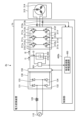
- FIG. 1 is a diagram showing a configuration example of a power converter according to Embodiment 1;
- FIG. 4 is a flow chart showing the operation of the control unit included in the power converter according to Embodiment 1;
- FIG. 2 is a diagram showing an example of a hardware configuration that realizes a control unit included in the power converter according to Embodiment 1;
- FIG. FIG. 4 is a block diagram showing a configuration example of a control unit included in a power converter according to Embodiment 2;
- FIG. 10 is a block diagram showing a configuration example of a q-axis current pulsation calculator included in the controller of the power converter according to Embodiment 2;
- FIG. 10 is a diagram showing an example of operation waveforms when a q-axis current pulsation calculation unit included in a control unit of a power converter according to Embodiment 2 is regarded as a pulsation detection unit;
- FIG. 11 is a diagram showing a configuration example of a power conversion device according to Embodiment 3; The figure which shows the structural example of the power converter device which concerns on Embodiment 4.
- FIG. 4 is a diagram showing an example of operating waveforms in a case where a second-order low-pass filter is not used as a specific frequency band pass section in a power converter as a comparative example;
- FIG. 10 is a diagram showing an example of operating waveforms when a secondary low-pass filter is used as a specific frequency band pass section in the power converter according to Embodiment 4;
- the block diagram which shows the structural example of the specific frequency band pass part with which the control part of the power converter device which concerns on Embodiment 6 is provided
- a power conversion device, a motor drive device, and a refrigeration cycle application device will be described below in detail based on the drawings.
- FIG. 1 is a diagram showing a configuration example of a power conversion device 1 according to Embodiment 1.
- Power converter 1 is connected to commercial power source 110 and compressor 315 .
- Power conversion device 1 converts first AC power having power supply voltage Vs supplied from commercial power supply 110, which is a single-phase commercial power supply, into second AC power having a desired amplitude and phase, and supplies the second AC power to compressor 315. do.
- the power conversion device 1 includes a reactor 120 , a rectification section 130 , a voltage detection section 501 , a smoothing section 200 , an inverter 310 , current detection sections 313 a and 313 b , and a control section 400 .
- a motor drive device 2 is configured by the power conversion device 1 and the motor 314 included in the compressor 315 .
- Reactor 120 is connected between commercial power supply 110 and rectifying section 130 .
- the rectifying section 130 has a bridge circuit configured by rectifying elements 131 to 134, rectifies the first AC power of the power supply voltage Vs supplied from the commercial power supply 110, and outputs the first AC power.
- the rectifier 130 performs full-wave rectification.
- the voltage detection unit 501 detects the DC bus voltage Vdc , which is the voltage across the smoothing unit 200, that is, the capacitor 210, charged by the current rectified by the rectifying unit 130 and flowing into the smoothing unit 200 from the rectifying unit 130. The resulting voltage value is output to the control unit 400 .
- Voltage detection unit 501 is a detection unit that detects the power state of capacitor 210 .
- the smoothing section 200 is connected to the output terminal of the rectifying section 130 .
- Smoothing section 200 has capacitor 210 as a smoothing element, and smoothes the power rectified by rectifying section 130 .
- Capacitor 210 is, for example, an electrolytic capacitor, a film capacitor, or the like.
- Capacitor 210 is connected to the output end of rectifying section 130 and has a capacity to smooth the power rectified by rectifying section 130 . It does not have a waveform shape, but has a waveform shape in which a voltage ripple corresponding to the frequency of the commercial power supply 110 is superimposed on the DC component, and does not pulsate greatly.
- the main component of the frequency of this voltage ripple is twice the frequency of the power supply voltage Vs. If the power input from commercial power supply 110 and the power output from inverter 310 do not change, the amplitude of this voltage ripple is determined by the capacitance of capacitor 210 . For example, it pulsates in such a range that the maximum value of the voltage ripple generated in the capacitor 210 is less than twice the minimum value.
- the inverter 310 is connected to both ends of the smoothing section 200 , that is, the capacitor 210 .
- Inverter 310 has switching elements 311a-311f and freewheeling diodes 312a-312f.
- Inverter 310 turns switching elements 311a to 311f on and off under the control of control unit 400, and converts the power output from rectifying unit 130 and smoothing unit 200 into second AC power having a desired amplitude and phase. of AC power is generated and output to the motor 314 of the compressor 315 .
- Current detection units 313 a and 313 b each detect a current value of one phase out of three-phase currents output from inverter 310 and output the detected current value to control unit 400 .
- Control unit 400 acquires two-phase current values among the three-phase current values output from inverter 310, thereby calculating the remaining one-phase current value output from inverter 310.
- Compressor 315 is a load having a motor 314 for driving the compressor. Motor 314 rotates according to the amplitude and phase of the second AC power supplied from inverter 310 to perform compression operation.
- the compressor 315 is a hermetic compressor used in an air conditioner or the like
- the load torque of the compressor 315 can often be regarded as a constant torque load.
- FIG. 1 shows a case where the motor windings are Y-connected, but this is an example and the present invention is not limited to this.
- the motor windings of the motor 314 may be delta-connection, or may be switchable between Y-connection and delta-connection.
- reactor 120 may be arranged after rectifying section 130 .
- the power conversion device 1 may include a booster section, or the rectifier section 130 may have the function of the booster section.
- the voltage detection section 501 and the current detection sections 313a and 313b may be collectively referred to as detection sections.
- the voltage value detected by the voltage detection section 501 and the current values detected by the current detection sections 313a and 313b may be referred to as detection values.
- the control unit 400 acquires the voltage value of the DC bus voltage Vdc of the smoothing unit 200 from the voltage detection unit 501, and obtains the second AC voltage having the desired amplitude and phase converted by the inverter 310 from the current detection units 313a and 313b. Get the current value of power.
- Control unit 400 controls the operation of inverter 310, specifically, the on/off of switching elements 311a to 311f included in inverter 310, using the detection values detected by the respective detection units. Also, the control unit 400 controls the operation of the motor 314 using the detection values detected by each detection unit.
- control unit 400 outputs second AC power including pulsation corresponding to the pulsation of power flowing from rectifying unit 130 into capacitor 210 of smoothing unit 200 from inverter 310 to compressor 315 as a load.
- the operation of the inverter 310 is controlled so as to
- the pulsation according to the pulsation of the power flowing into the capacitor 210 of the smoothing section 200 is, for example, the pulsation that varies depending on the frequency of the pulsation of the power flowing into the capacitor 210 of the smoothing section 200 .
- the control unit 400 suppresses the current flowing through the capacitor 210 of the smoothing unit 200 .
- the control unit 400 does not have to use all the detection values acquired from each detection unit, and may perform control using some of the detection values.
- the control unit 400 performs control so that any one of the speed, voltage, and current of the motor 314 is in a desired state.
- the motor 314 is used to drive the compressor 315 and the compressor 315 is a hermetic compressor, attaching a position sensor for detecting the rotor position to the motor 314 is structurally and economically advantageous. Since it is difficult, the control unit 400 controls the motor 314 without a position sensor.
- Position sensorless control methods for the motor 314 include primary magnetic flux constant control and sensorless vector control. In this embodiment, sensorless vector control will be described as an example. It should be noted that the control method described below can be applied to the primary magnetic flux constant control or other methods with minor changes.
- control unit 400 controls the operations of inverter 310 and motor 314 using dq rotation coordinates that rotate in synchronization with the rotor position of motor 314, as will be described later.
- control unit 400 has specific frequency band pass unit 450 that passes a specified frequency band of power supply ripple components included in DC bus voltage Vdc detected by voltage detection unit 501 .
- Control unit 400 controls operations of inverter 310 and motor 314 using DC bus voltage V dc ′ after DC bus voltage V dc detected by voltage detection unit 501 has passed through specific frequency band pass unit 450 .
- the DC bus voltage V dc detected by the voltage detection unit 501 is referred to as the first DC bus voltage
- the DC bus voltage V dc ′ after passing through the specific frequency band pass unit 450 is referred to as the second DC bus voltage.
- voltage Sometimes referred to as voltage.
- the power supply pulsating component included in the DC bus voltage Vdc detected by the voltage detection unit 501 has a frequency n times that of the commercial power supply 110, that is, the DC bus voltage Vdc pulsates at a frequency n times that of the commercial power supply 110.
- an m-order filter is applied as specific frequency band pass section 450 in this embodiment.
- the frequency n times that of the commercial power supply 110 specifically means a frequency n times the frequency of the power supply voltage Vs supplied from the commercial power supply 110 .
- n and m are integers of 2 or more.
- an FIR Finite Impulse Response
- IIR Intelligent Impulse Impulse Response
- FIG. 2 is a flow chart showing the operation of the control unit 400 included in the power conversion device 1 according to the first embodiment.
- the control unit 400 acquires the DC bus voltage Vdc of the capacitor 210, which is the detected value, from the voltage detection unit 501 (step S1).
- the control unit 400 allows the acquired DC bus voltage Vdc to pass through the specific frequency band pass unit 450 (step S2).
- the control unit 400 controls the inverter 310 and the like using the DC bus voltage Vdc ' after passing through the specific frequency band pass unit 450 (step S3).
- FIG. 3 is a diagram showing an example of a hardware configuration that implements the control unit 400 included in the power conversion device 1 according to Embodiment 1. As shown in FIG. Control unit 400 is implemented by processor 91 and memory 92 .
- the processor 91 is a CPU (Central Processing Unit, central processing unit, processing unit, arithmetic unit, microprocessor, microcomputer, processor, DSP (Digital Signal Processor)), or a system LSI (Large Scale Integration).
- the memory 92 includes RAM (Random Access Memory), ROM (Read Only Memory), flash memory, EPROM (Erasable Programmable Read Only Memory), EEPROM (registered trademark) (Electrically Erasable Programmable Read Non-volatile or volatile such as Only Memory)
- RAM Random Access Memory
- ROM Read Only Memory
- flash memory flash memory
- EPROM Erasable Programmable Read Only Memory
- EEPROM registered trademark
- a semiconductor memory can be exemplified.
- the memory 92 is not limited to these, and may be a magnetic disk, an optical disk, a compact disk, a mini disk, or a DVD (Digital Versatile Disc).
- the control unit 400 acquires the DC bus voltage Vdc detected by the voltage detection unit 501, and passes it through the specific frequency band pass unit 450. Inverter 310 and the like are controlled using the DC bus voltage Vdc ', which is the DC bus voltage Vdc that has been increased. Thereby, control unit 400 can improve the accuracy of control using DC bus voltage Vdc .
- Embodiment 2 a case where a high-pass filter is used as a specific example of specific frequency band pass section 450 will be described.
- Commercial power supply 110 connected to power converter 1 in the second embodiment is a single-phase commercial power supply as shown in FIG.
- FIG. 4 is a block diagram showing a configuration example of the control unit 400 included in the power converter 1 according to Embodiment 2.
- the control unit 400 includes a rotor position estimation unit 401, a speed control unit 402, a flux-weakening control unit 403, a current control unit 404, coordinate conversion units 405 and 406, a PWM signal generation unit 407, a q-axis current A pulsation calculator 408 , an adder 409 , and a specific frequency band passer 450 are provided.
- the rotor position estimating unit 401 calculates the direction of the rotor magnetic poles on the dq axis for the rotor (not shown) of the motor 314 from the dq-axis voltage command vector V dq * and the dq-axis current vector i dq applied to the motor 314. Estimate an estimated phase angle ⁇ est and an estimated speed ⁇ est , which is the rotor speed.
- a speed control unit 402 generates a q-axis current command i qDC * from the speed command ⁇ * and the estimated speed ⁇ est . Specifically, the speed control unit 402 automatically adjusts the q-axis current command iqDC * so that the speed command ⁇ * and the estimated speed ⁇ est match.
- the speed command ⁇ * is, for example, a temperature detected by a temperature sensor (not shown) or a setting indicated by a remote control that is an operation unit (not shown). It is based on information indicating temperature, operation mode selection information, operation start and operation end instruction information, and the like.
- the operation modes are, for example, heating, cooling, and dehumidification.
- the flux-weakening control unit 403 automatically adjusts the d-axis current command i d * so that the absolute value of the dq-axis voltage command vector V dq * falls within the limit value of the voltage limit value V lim * . Further, the flux-weakening control unit 403 performs flux-weakening control in consideration of the q-axis current ripple command i qrip * calculated by the q-axis current ripple calculation unit 408 .
- the flux-weakening control can be broadly classified into a method of calculating the d-axis current command id * from the equation of the voltage limit ellipse, and a method in which the deviation of the absolute value between the voltage limit value Vlim * and the dq-axis voltage command vector Vdq * is zero. There are two methods of calculating the d-axis current command i d * so that
- the current control unit 404 controls the current flowing through the motor 314 using the q-axis current command i q * and the d-axis current command id * to generate the dq-axis voltage command vector V dq * . Specifically, the current control unit 404 automatically adjusts the dq - axis voltage command vector V dq * so that the dq-axis current vector i dq follows the d-axis current command id * and the q-axis current command i q *. .
- the dq-axis voltage command vector V dq * may be simply referred to as the dq-axis voltage command.
- the coordinate conversion unit 405 coordinates-converts the dq-axis voltage command vector V dq * from the dq coordinates into the voltage command V uvw * of the AC quantity according to the estimated phase angle ⁇ est .
- a coordinate transformation unit 406 coordinates-transforms the current I uvw flowing through the motor 314 from an alternating current quantity to a dq-axis current vector i dq of dq coordinates in accordance with the estimated phase angle ⁇ est .
- the control unit 400 controls the two-phase current values detected by the current detection units 313a and 313b among the three-phase current values output from the inverter 310, and It can be obtained by calculating the current value of the remaining one phase using the current values of the two phases. Further, in the present embodiment, a method of acquiring the current value of the current flowing in the motor 314 and reproducing the three-phase current is described. A method of acquiring values and reproducing three-phase currents may be used.
- PWM signal generation unit 407 generates a PWM signal based on voltage command V uvw * coordinate-transformed by coordinate transformation unit 405 .
- Control unit 400 applies a voltage to motor 314 by outputting the PWM signal generated by PWM signal generation unit 407 to switching elements 311 a to 311 f of inverter 310 .
- a q-axis current ripple calculator 408 calculates the q-axis current ripple using the DC bus voltage Vdc ' and generates the q -axis current ripple command iqrip * , which is the ripple component of the q-axis current command iq * . do. Specifically, the q-axis current ripple calculation unit 408 calculates the q-axis current ripple command i qrip * based on the DC bus voltage V dc ′ detected by the voltage detection unit 501 and passed through the specific frequency band pass unit 450 . to calculate Since the pulsation amplitude of the q -axis current iq varies depending on the drive conditions of the motor 314, the q-axis current pulsation calculator 408 appropriately considers the drive conditions to determine the amplitude.
- Addition unit 409 adds q-axis current command i qDC * output from speed control unit 402 and q-axis current ripple command i qrip * calculated by q-axis current ripple calculation unit 408 to obtain a q-axis current command.
- i q * is generated and output to current control section 404 .
- FIG. 5 is a block diagram showing a configuration example of the q-axis current ripple calculator 408 included in the controller 400 of the power converter 1 according to the second embodiment.
- the q-axis current pulsation calculator 408 includes a subtractor 420 , Fourier coefficient calculators 421 to 424 , PID (Proportional Integral Differential) controllers 425 to 428 , and an AC restorer 429 . Note that FIG. 5 also shows a specific frequency band pass section 450 .
- the subtraction unit 420 calculates the deviation between the target value of 0 and the DC bus voltage Vdc '.
- the Fourier coefficient calculators 421 to 424 use the power frequency of the commercial power source 110 as the 1f component, and calculate the amplitudes of the sin2f component, cos2f component, sin4f component, and cos4f component included in the deviation calculated by the subtractor 420.
- the Fourier coefficient calculators 421 to 424 differ only in target specific frequency components, and have the same calculation contents.
- the PID controllers 425-428 are connected to one of the Fourier coefficient calculators 421-424, and proportional- Implement integral-derivative control.
- the PID controllers 425 to 428 differ in the values input from the connected Fourier coefficient calculators 421 to 424, but have the same control content except for the target specific frequency component.
- the AC restorer 429 restores the AC signal using the outputs from the PID controllers 425 to 428, and outputs the restored AC signal as the q-axis current pulsation command i qrip * .
- the DC bus voltage Vdc is obtained by integrating the charging/discharging current I3 of the capacitor 210 and dividing it by the capacity of the capacitor 210, there is a difference between the charging/discharging current I3 of the capacitor 210 and the DC bus voltage Vdc .
- the AC restoring section 429 must determine the q-axis current pulsation command i qrip * taking this phase difference into consideration.
- the restoration unit 429 sets the restored signals to sin2( ⁇ int + ⁇ offset ), cos2( ⁇ int + ⁇ offset ), sin4( ⁇ int + ⁇ offset ), and cos4( ⁇ int + ⁇ offset ).
- the AC restorer 429 can determine the q-axis current pulsation command i qrip * by calculating the product sum of the outputs from the PID controllers 425 to 428 and the restored signal. As shown in FIG.
- the input current from the rectifying unit 130 to the capacitor 210 of the smoothing unit 200 is the input current I1
- the output current from the capacitor 210 of the smoothing unit 200 to the inverter 310 is output.
- a current I2 is assumed, and a charging/discharging current of the capacitor 210 of the smoothing section 200 is assumed to be a charging/discharging current I3.
- Control unit 400 uses specific frequency band pass unit 450, which is a high-pass filter, to remove the DC component from DC bus voltage Vdc detected by voltage detection unit 501, and q-axis current ripple calculation unit 408 performs pulsation detection processing. , PID control, and AC restoration processing. As a result, control unit 400 improves the stability of the smoothing element current reduction control that suppresses charge/discharge current I3 of capacitor 210, and reduces pulsation of DC bus voltage Vdc and charge/discharge current I3 of capacitor 210. be able to. This is because the pulsation detection error can be suppressed by removing the DC component from the DC bus voltage Vdc by the specific frequency band pass section 450, which is a high-pass filter.
- the specific frequency band pass section 450 which is a high-pass filter, may be composed of an FIR filter or an IIR filter.
- a low-pass filter as in Equation (1) may be used to equivalently realize a high-pass filter.
- the second term on the right side represents a low-pass filter.
- the second-order low-pass filter is used in equation (1), other filters such as a first-order low-pass filter that attenuates the high-frequency range may be used.
- s is the Laplace operator
- ⁇ is the damping coefficient
- ⁇ n is the cutoff angular frequency.
- the damping coefficient ⁇ is a parameter that governs the oscillatory nature of the response.
- a filter using .sqroot.(2) for the attenuation coefficient .zeta. is called a second-order Butterworth filter, and has the characteristic that the signal becomes -3 dB at the cut-off angular frequency .omega.n . Note that ⁇ (2) indicates the square root of two.
- the attenuation performance of the pulsation component can be improved from -20 dB/decade to -40 dB/decade compared to the first-order low-pass filter, so the response performance and the attenuation performance of the pulsation component can be compatible.
- the damping coefficient ⁇ is assumed to be ⁇ (2) so that the second-order low-pass filter becomes a second-order Butterworth filter .
- the point at which is ⁇ 3 dB may be changed.
- the cutoff angular frequency ⁇ n for the frequency component to be attenuated, the pulsation component can be removed from the signal.
- the cutoff angular frequency ⁇ n should be designed to be less than the pulsating component ⁇ 2f twice the power frequency.
- FIG. 6 is a diagram showing an example of operation waveforms when the q-axis current pulsation calculator 408 included in the control unit 400 of the power converter 1 according to Embodiment 2 is regarded as a pulsation detector.
- the upper diagram shows the original detection signal, which is the DC bus voltage Vdc
- the lower diagram shows the detection signal, which is the q-axis current pulsation command i qrip * .
- the horizontal axis indicates time.
- the solid line is the true value of the pulsation component to be detected.
- the high-pass filter is not used for the detection source signal, it can be seen that the DC component is superimposed on the detection signal. Due to this DC superimposition, the effect of control such as the aforementioned smoothing element current reduction control is deteriorated.
- the present embodiment by removing the DC component from the detection source signal using a high-pass filter and then performing pulsation detection, it can be seen that the signal can be detected without superimposing the DC component.
- control unit 400 can improve the accuracy of pulsation detection and improve the performance of control such as smoothing element current reduction control.
- control unit 400 uses a high-pass filter for the detected value of DC bus voltage Vdc , so that low-frequency pulsation components are superimposed on DC bus voltage Vdc and the motor current, resulting in copper loss of motor 314 and inverter 310. An increase in conduction loss can be prevented.
- the control unit 400 performs smoothing element current reduction control, for example, vibration suppression control that suppresses vibrations generated in the motor 314, the compressor 315, and the like. can also improve control performance.
- the control unit 400 uses a secondary high-pass filter as the specific frequency band pass unit 450 .
- the control unit 400 sets the control band of the specific frequency band pass unit 450 to twice or less than the frequency of the single-phase commercial power source, and controls the second-order or lower component of the single-phase commercial power source frequency. is attenuated at a rate of -40 dB/decade or more.
- a single-phase commercial power frequency is generally 50 Hz or 60 Hz.
- control unit 400 uses a high-pass filter as specific frequency band pass unit 450. , it is possible to improve the performance of control such as smoothing element current reduction control for suppressing the charge/discharge current I3 of the capacitor 210 .
- Embodiment 3 In the second embodiment, as an example of using a high-pass filter as specific frequency band pass section 450, the case where commercial power supply 110 is a single-phase commercial power supply has been described. In the third embodiment, as an example of using a high-pass filter as the specific frequency band pass section 450, a case where the commercial power supply is a three-phase commercial power supply will be described.
- FIG. 7 is a diagram showing a configuration example of a power converter 1a according to Embodiment 3.
- Power converter 1 a is connected to commercial power source 110 a and compressor 315 .
- Power converter 1a converts first AC power of power supply voltage Vs supplied from commercial power supply 110a, which is a three-phase commercial power supply, into second AC power having a desired amplitude and phase, and supplies the second AC power to compressor 315. do.
- the power converter 1a includes reactors 120 to 122, a rectifying section 130a, a voltage detecting section 501, a smoothing section 200, an inverter 310, current detecting sections 313a and 313b, and a control section 400.
- the power converter 1a and the motor 314 included in the compressor 315 constitute a motor drive device 2a.
- Reactors 120 to 122 are connected between commercial power supply 110a and rectifying section 130a.
- Rectifying section 130a has a rectifying circuit configured by rectifying elements 131 to 136, and rectifies and outputs first AC power of power supply voltage Vs supplied from commercial power supply 110a.
- the rectifier 130a performs full-wave rectification.
- the voltage detection unit 501 detects the DC bus voltage Vdc , which is the voltage across the smoothing unit 200, that is, the capacitor 210, charged by the current rectified by the rectifying unit 130a and flowing into the smoothing unit 200 from the rectifying unit 130a. The resulting voltage value is output to the control unit 400 .
- Voltage detection unit 501 is a detection unit that detects the power state of capacitor 210 .
- the smoothing section 200 is connected to the output terminal of the rectifying section 130a.
- the smoothing section 200 has a capacitor 210 as a smoothing element, and smoothes the power rectified by the rectifying section 130a.
- Capacitor 210 is, for example, an electrolytic capacitor, a film capacitor, or the like.
- Capacitor 210 is connected to the output end of rectifying section 130a and has a capacity for smoothing the power rectified by rectifying section 130a. It does not have a waveform shape, but has a waveform shape in which a voltage ripple corresponding to the frequency of the commercial power supply 110a is superimposed on the DC component, and does not pulsate greatly.
- the main component of the frequency of this voltage ripple is a component six times the frequency of the power supply voltage Vs. If the power input from commercial power supply 110 a and the power output from inverter 310 do not change, the amplitude of this voltage ripple is determined by the capacity of capacitor 210 . For example, it pulsates in such a range that the maximum value of the voltage ripple generated in the capacitor 210 is less than twice the minimum value.
- the configuration and operation of the control unit 400 are the same as those of the control unit 400 of Embodiment 2, but the setting of the specific frequency band pass unit 450 is different.
- a voltage ripple is superimposed on the voltage generated in the capacitor 210 by smoothing, and the frequency of the voltage ripple is twice the frequency of the power supply voltage Vs when the commercial power supply 110 is a single-phase commercial power supply.
- the main component when the commercial power supply 110a is a three-phase commercial power supply, the main component is a component six times the frequency of the power supply voltage Vs.
- the specific frequency band pass section 450 which is a high-pass filter, may be composed of an FIR filter or an IIR filter.
- a low-pass filter may be used as the specific frequency band pass unit 450 to equivalently realize a high-pass filter, as in the second embodiment.
- the damping coefficient ⁇ is set to ⁇ (2) so that the second-order low-pass filter becomes a second-order Butterworth filter as in the second embodiment. may be adjusted to change the point at which the signal is -3 dB.
- the cutoff angular frequency ⁇ n for the frequency component to be attenuated, the pulsation component can be removed from the signal.
- the cut-off angular frequency ⁇ n should be designed to be less than the pulsating component ⁇ 6f six times the power frequency.
- control unit 400 controls that the connected power source is the commercial power source 110a that is the three-phase commercial power source, as in the case of the commercial power source 110 that is the single-phase commercial power source. Even if there is, it is possible to improve the accuracy of pulsation detection and improve the performance of control such as smoothing element current reduction control.
- control unit 400 uses a high-pass filter for the detected value of DC bus voltage Vdc , so that low-frequency pulsation components are superimposed on DC bus voltage Vdc and the motor current, resulting in copper loss of motor 314 and inverter 310. An increase in conduction loss can be prevented.
- control unit 400 performs smoothing element current reduction control, for example, vibration suppression control that suppresses vibrations generated in the motor 314, the compressor 315, and the like. can also improve control performance.
- the control unit 400 uses a secondary high-pass filter as the specific frequency band pass unit 450 .
- the control unit 400 sets the control band of the specific frequency band pass unit 450 to six times or less than the frequency of the three-phase commercial power source, and controls the sixth-order or lower component of the frequency of the three-phase commercial power source. is attenuated at a rate of -40 dB/decade or more.
- a three-phase commercial power frequency is generally 50 Hz or 60 Hz.
- control unit 400 uses a high-pass filter as specific frequency band pass unit 450. Therefore, as in the second embodiment, it is possible to improve the performance of control such as smoothing element current reduction control for suppressing charge/discharge current I3 of capacitor 210 .
- Embodiment 4 a case where a low-pass filter is used as a specific example of specific frequency band pass section 450 will be described.
- the commercial power source 110 connected to the power converter in the fourth embodiment is assumed to be a single-phase commercial power source.
- FIG. 8 is a diagram showing a configuration example of a power converter 1b according to Embodiment 4.
- Power converter 1 b is connected to commercial power supply 110 and compressor 315 .
- Power conversion device 1b converts first AC power having power supply voltage Vs supplied from commercial power supply 110, which is a single-phase commercial power supply, into second AC power having desired amplitude and phase, and supplies the second AC power to compressor 315. do.
- the power converter 1b includes a reactor 120, a rectifying section 130, a boosting section 150, a voltage detecting section 501, a smoothing section 200, an inverter 310, current detecting sections 313a and 313b, and a control section 400b.
- the power converter 1b and the motor 314 included in the compressor 315 constitute a motor driving device 2b.
- the booster 150 boosts the voltage of the DC power output from the rectifier 130 under the control of the controller 400b.
- the configuration of the booster section 150 is, for example, a booster circuit using reactors, switching elements, diodes, etc., but it may be a general configuration and is not particularly limited.
- Control unit 400b controls the operation of inverter 310 and motor 314 in the same manner as control unit 400, and operates booster unit 150 so that DC bus voltage Vdc detected by voltage detection unit 501 becomes a desired value.
- Control In the present embodiment, one control unit 400b controls the operations of inverter 310, motor 314, and booster unit 150, but the present invention is not limited to this.
- a control unit that controls the operations of inverter 310 and motor 314 and a control unit that controls the operation of booster unit 150 may be separated.
- the structure can be simplified as the whole power converter 1b, so that the number of control parts is small.
- control section 400b uses a secondary low-pass filter as specific frequency band pass section 450.
- FIG. Control unit 400b uses a second-order low-pass filter to remove the pulsation component of 2n times the power supply frequency generated in commercial power supply 110 from DC bus voltage Vdc , and the low-frequency pulsation component is removed from DC bus voltage Vdc. ' to prevent it from being superimposed.
- the control unit 400b uses the DC bus voltage V dc ′ from which the high-frequency component, that is, the pulsating component is removed by a second-order low-pass filter. can be done.
- a second-order low-pass filter is represented by equation (2) as described above.
- the damping coefficient ⁇ is a parameter that governs the oscillatory nature of the response.
- a filter using .sqroot.(2) for the attenuation coefficient .zeta. is called a second-order Butterworth filter, and has the characteristic that the signal becomes -3 dB at the cut-off angular frequency .omega.n .
- the attenuation performance of the pulsation component can be improved from -20 dB/decade to -40 dB/decade compared to the first-order low-pass filter, so the response performance and the attenuation performance of the pulsation component can be compatible.
- the damping coefficient ⁇ is assumed to be ⁇ (2) so that the second-order low-pass filter becomes a second-order Butterworth filter .
- the point at which is ⁇ 3 dB may be changed.
- the cutoff angular frequency ⁇ n for the frequency component to be attenuated, the pulsation component can be removed from the signal.
- the cutoff angular frequency ⁇ n should be designed to be less than the pulsating component ⁇ 2f twice the power frequency.
- FIG. 9 is a diagram showing an example of operating waveforms in a case where a secondary low-pass filter is not used as a specific frequency band pass section in a power converter as a comparative example.
- the upper diagram shows the DC bus voltage Vdc
- the lower diagram shows the motor current.
- the horizontal axis indicates time.
- a secondary low-pass filter is not used for the DC bus voltage Vdc , the average value of the DC bus voltage Vdc cannot be obtained due to errors in detection timing, etc., and a low-frequency pulsating component is superimposed on the DC bus voltage Vdc. may be In such a case, a low-frequency pulsation component is superimposed on the DC bus voltage Vdc due to the feedback control of the DC bus voltage control. In addition, the motor current also pulsates due to the pulsation of the DC bus voltage Vdc . As a result, problems such as an increase in loss and a narrow motor drive range occur.
- FIG. 10 is a diagram showing an example of operating waveforms when a secondary low-pass filter is used as the specific frequency band pass section 450 in the power converter 1b according to the fourth embodiment.
- the control unit 400b uses a second-order low-pass filter to attenuate the pulsating component of the DC bus voltage Vdc , thereby suppressing superimposition of low-frequency components that are less than twice the power supply frequency due to voltage detection timing errors. be able to.
- control unit 400b can reduce the low-order harmonics of the motor current, so that the conduction loss of inverter 310 and the copper loss of motor 314 can be reduced.
- the control unit 400b can also obtain a noise reduction effect by being able to remove the beat component.
- the control unit 400b uses the DC bus voltage V dc ′ from which the high-frequency component, that is, the pulsating component is removed by the secondary low-pass filter, so that, for example, the operating region of the flux-weakening control caused by the pulsating component is Restrictions can be improved.
- the operating region of the flux-weakening control caused by the pulsating component is Restrictions can be improved.
- These effects are especially apparent in a region where the current is large, such as a low-speed, high-load region, and in operating conditions such as a large pulsation of the 2n component generated in the DC voltage output from the rectifier 130 without boosting operation.
- the pulsation removal effect of the low-pass filter is large.
- the control unit 400b uses a secondary low-pass filter as the specific frequency band pass unit 450.
- the power converter 1b includes a booster 150 that boosts the voltage of the DC power output from the rectifier 130 .
- the control unit 400b sets the control band of the specific frequency band passing unit 450 to be equal to or less than twice the single-phase commercial power supply frequency, and sets n to an integer of 2 or more to set the single-phase commercial power supply frequency.
- the 2n-order component is attenuated at a rate of -40 dB/decade or more, and the operation of the booster 150 is controlled using the DC bus voltage V dc '.
- Control unit 400b is realized by processor 91 and memory 92, similar to control unit 400 of the first embodiment.
- control unit 400b uses a low-pass filter as specific frequency band pass unit 450. , it is possible to improve the limitation of the operating region of the flux-weakening control caused by the pulsation component.
- Embodiment 5 in the fourth embodiment, as an example of using a low-pass filter as specific frequency band pass section 450, the case where commercial power supply 110 is a single-phase commercial power supply has been described. In the fifth embodiment, as an example of using a low-pass filter as specific frequency band pass section 450, a case where commercial power source 110a is a three-phase commercial power source will be described.
- FIG. 11 is a diagram showing a configuration example of a power converter 1c according to Embodiment 5.
- Power converter 1c is connected to commercial power source 110a and compressor 315 .
- Power conversion device 1c converts first AC power having power supply voltage Vs supplied from commercial power supply 110a, which is a three-phase commercial power supply, into second AC power having a desired amplitude and phase, and supplies the second AC power to compressor 315. do.
- the power conversion device 1c includes reactors 120 to 122, a rectifying unit 130a, a boosting unit 150, a voltage detecting unit 501, a smoothing unit 200, an inverter 310, current detecting units 313a and 313b, a control unit 400b, Prepare.
- the power converter 1c and the motor 314 included in the compressor 315 constitute a motor driving device 2c.
- the configuration and operation of the control unit 400b are the same as those of the control unit 400b of Embodiment 4, but the setting of the specific frequency band pass unit 450 is different.
- a voltage ripple is superimposed on the voltage generated in the capacitor 210 by smoothing, and the frequency of the voltage ripple is twice the frequency of the power supply voltage Vs when the commercial power supply 110 is a single-phase commercial power supply.
- the main component when the commercial power supply 110a is a three-phase commercial power supply, the main component is a component six times the frequency of the power supply voltage Vs.
- control section 400b uses a secondary low-pass filter as specific frequency band pass section 450.
- FIG. The control unit 400b uses a second-order low-pass filter to remove the pulsation component of the 6n-fold component of the power supply frequency generated in the commercial power supply 110a from the DC bus voltage Vdc , and the low-frequency pulsation component is removed from the DC bus voltage Vdc. ' to prevent it from being superimposed.
- the control unit 400b uses the DC bus voltage V dc ′ from which the high-frequency component, that is, the pulsating component is removed by a second-order low-pass filter. can be done.
- the damping coefficient ⁇ is set to ⁇ (2) so that the second-order low-pass filter becomes a second-order Butterworth filter as in the fourth embodiment, but the cut-off angular frequency ⁇ n and the damping coefficient ⁇ may be adjusted to change the point at which the signal is -3 dB.
- the cutoff angular frequency ⁇ n for the frequency component to be attenuated, the pulsation component can be removed from the signal.
- the cut-off angular frequency ⁇ n should be designed to be less than the pulsating component ⁇ 6f six times the power frequency.
- the control unit 400b uses a secondary low-pass filter to attenuate the pulsating component of the DC bus voltage Vdc , so that the connected power supply is a three-phase commercial power supply, as in the case of the commercial power supply 110, which is a single-phase commercial power supply. Even with the commercial power supply 110a, it is possible to suppress the superposition of low-frequency components of twice or less than the power supply frequency due to an error in voltage detection timing. As a result, control unit 400b can reduce the low-order harmonics of the motor current, so that the conduction loss of inverter 310 and the copper loss of motor 314 can be reduced. Moreover, the control unit 400b can also obtain a noise reduction effect by being able to remove the beat component.
- the control unit 400b uses the DC bus voltage V dc ′ from which the high-frequency component, that is, the pulsating component is removed by the secondary low-pass filter, so that, for example, the operating region of the flux-weakening control caused by the pulsating component is Restrictions can be improved.
- the operating region of the flux-weakening control caused by the pulsating component is Restrictions can be improved.
- These effects are especially noticeable in a region where the current is large, such as a low-speed, high-load region, or in operating conditions such as a large pulsation of the 6n component generated in the DC voltage output from the rectifying unit 130a without boosting operation.
- the pulsation removal effect of the low-pass filter is large.
- the control unit 400b uses a secondary low-pass filter as the specific frequency band pass unit 450.
- the power converter 1c includes a booster 150 that boosts the voltage of the DC power output from the rectifier 130a.
- the control unit 400b sets the control band of the specific frequency band pass unit 450 to 6 times or less than the three-phase commercial power source frequency, and sets n to an integer of 2 or more to control the three-phase commercial power source frequency.
- the 6n-th order component is attenuated at a rate of -40 dB/decade or more, and the operation of the booster 150 is controlled using the DC bus voltage V dc '.
- control unit 400b uses a low-pass filter as specific frequency band pass unit 450. Therefore, as in the fourth embodiment, it is possible to improve the limitation of the operating region of the flux-weakening control caused by the pulsation component.
- Embodiment 6 describes a case where specific frequency band pass section 450 includes a plurality of filters, selects an output from each filter, and outputs it as DC bus voltage V dc '.
- the specific frequency band pass section 450 of this embodiment can be applied to any of the power converters of the first to fifth embodiments.
- the power converter 1 of Embodiments 1 and 2 will be described as an example.
- FIG. 12 is a block diagram showing a configuration example of the specific frequency band pass section 450 included in the control section 400 of the power converter 1 according to Embodiment 6. As shown in FIG.
- the specific frequency band pass section 450 includes a first filter 451 , a second filter 452 and a selection section 453 .
- the first filter 451 is an n-th order filter where n is an integer of 2 or more. That is, the first filter 451 is a filter with an order of two or more.
- the first filter 451 is a high-pass filter in the second and third embodiments, and a low-pass filter in the fourth and fifth embodiments.
- An FIR filter, an IIR filter, or the like may be used as the first filter 451 .
- the second filter 452 is a high-pass filter in the second and third embodiments, and a low-pass filter in the fourth and fifth embodiments.
- An FIR filter, an IIR filter, or the like may be used as the second filter 452 .
- the selection unit 453 selects the output from the first filter 451 or the output from the second filter 452 according to the calculation load of the control unit 400 .
- the selection unit 453 acquires the signal ALM indicating the calculation load of the control unit 400 .
- the selection unit 453 may acquire the signal ALM indicating the computational load of the control unit 400 from a configuration (not shown) that monitors the processing of the control unit 400, or may acquire the signal ALM from the configuration of the control unit 400 shown in FIG. It may be acquired from a configuration other than the passing unit 450 .
- the signal ALM is, for example, an operation time indicating the time required for the specified operation, an operation speed indicating the specified speed of the operation, and the like.
- the selection unit 453 attenuates the pulsating component of the DC bus voltage Vdc using the first filter 451, which is a high-order filter, in an operation region where the calculation load is light and the calculation time is sufficient.
- the selection unit 453 selects the output from the second filter 452, which is a first-order filter, in an operation region where the calculation load is heavy and the calculation time is short.
- the control unit 400 allows the specific frequency band pass unit 450 to output the output from the second filter 452 as the DC bus voltage V dc ', so that the calculation time can be accommodated for other processing when the calculation load is heavy. can be done.
- the specific frequency band pass section 450 uses only the output from one of the first filter 451 and the second filter 452, the calculation is stopped for the filter whose output is not selected. You may let Accordingly, the specific frequency band pass section 450 can further reduce the computational load of the control section 400 .
- the specific frequency band pass section 450 may include a plurality of filters with different orders as the first filter 451 . As a result, when the calculation load of control section 400 becomes heavy, specific frequency band pass section 450 can switch to output from a filter with a lower order in stages according to the value of signal ALM.
- the specific frequency band pass unit 450 of the control unit 400 switches the order of the filter to be used according to the calculation load of the control unit 400. and As a result, the specific frequency band pass unit 450 uses a high-order filter when there is a margin in calculation time, and uses a low-order filter when there is no margin in calculation time, according to the calculation load of the control unit 400. be able to.
- FIG. 13 is a diagram showing a configuration example of a refrigeration cycle equipment 900 according to Embodiment 7.
- a refrigerating cycle-applied equipment 900 according to the seventh embodiment includes the power converter 1 described in the first and second embodiments.
- the refrigerating cycle applied equipment 900 can also include the power conversion device 1a described in Embodiment 3, the power conversion device 1b described in Embodiment 4, the power conversion device 1c described in Embodiment 5, and the like.
- the power conversion device 1 is provided will be described.
- the refrigerating cycle applied equipment 900 according to Embodiment 7 can be applied to products equipped with a refrigerating cycle, such as air conditioners, refrigerators, freezers, and heat pump water heaters.
- a refrigerating cycle such as air conditioners, refrigerators, freezers, and heat pump water heaters.
- constituent elements having functions similar to those of the first embodiment are denoted by the same reference numerals as those of the first embodiment.
- Refrigerating cycle applied equipment 900 includes compressor 315 incorporating motor 314 according to Embodiment 1, four-way valve 902, indoor heat exchanger 906, expansion valve 908, and outdoor heat exchanger 910 with refrigerant pipe 912. attached through
- a compression mechanism 904 that compresses the refrigerant and a motor 314 that operates the compression mechanism 904 are provided inside the compressor 315 .
- the refrigeration cycle applied equipment 900 can perform heating operation or cooling operation by switching operation of the four-way valve 902 .
- the compression mechanism 904 is driven by a variable speed controlled motor 314 .
- the refrigerant is pressurized by the compression mechanism 904 and sent out through the four-way valve 902, the indoor heat exchanger 906, the expansion valve 908, the outdoor heat exchanger 910, and the four-way valve 902. Return to compression mechanism 904 .
- the refrigerant is pressurized by the compression mechanism 904 and sent through the four-way valve 902, the outdoor heat exchanger 910, the expansion valve 908, the indoor heat exchanger 906, and the four-way valve 902. Return to compression mechanism 904 .
- the indoor heat exchanger 906 acts as a condenser to release heat, and the outdoor heat exchanger 910 acts as an evaporator to absorb heat.
- the outdoor heat exchanger 910 acts as a condenser to release heat, and the indoor heat exchanger 906 acts as an evaporator to absorb heat.
- the expansion valve 908 reduces the pressure of the refrigerant to expand it.
Landscapes
- Engineering & Computer Science (AREA)
- Power Engineering (AREA)
- Physics & Mathematics (AREA)
- Mechanical Engineering (AREA)
- Thermal Sciences (AREA)
- General Engineering & Computer Science (AREA)
- Control Of Ac Motors In General (AREA)
- Inverter Devices (AREA)
Priority Applications (4)
| Application Number | Priority Date | Filing Date | Title |
|---|---|---|---|
| PCT/JP2021/044204 WO2023100305A1 (ja) | 2021-12-02 | 2021-12-02 | 電力変換装置、モータ駆動装置および冷凍サイクル適用機器 |
| US18/714,233 US20250219553A1 (en) | 2021-12-02 | 2021-12-02 | Power converting apparatus, motor drive apparatus, and refrigeration-cycle application device |
| CN202180104534.7A CN118339750A (zh) | 2021-12-02 | 2021-12-02 | 电力转换装置、马达驱动装置以及制冷循环应用设备 |
| JP2023564352A JPWO2023100305A1 (https=) | 2021-12-02 | 2021-12-02 |
Applications Claiming Priority (1)
| Application Number | Priority Date | Filing Date | Title |
|---|---|---|---|
| PCT/JP2021/044204 WO2023100305A1 (ja) | 2021-12-02 | 2021-12-02 | 電力変換装置、モータ駆動装置および冷凍サイクル適用機器 |
Publications (1)
| Publication Number | Publication Date |
|---|---|
| WO2023100305A1 true WO2023100305A1 (ja) | 2023-06-08 |
Family
ID=86611663
Family Applications (1)
| Application Number | Title | Priority Date | Filing Date |
|---|---|---|---|
| PCT/JP2021/044204 Ceased WO2023100305A1 (ja) | 2021-12-02 | 2021-12-02 | 電力変換装置、モータ駆動装置および冷凍サイクル適用機器 |
Country Status (4)
| Country | Link |
|---|---|
| US (1) | US20250219553A1 (https=) |
| JP (1) | JPWO2023100305A1 (https=) |
| CN (1) | CN118339750A (https=) |
| WO (1) | WO2023100305A1 (https=) |
Citations (6)
| Publication number | Priority date | Publication date | Assignee | Title |
|---|---|---|---|---|
| JPH10271900A (ja) * | 1997-03-28 | 1998-10-09 | Toshiba Corp | 電力変換装置 |
| JP2001095294A (ja) * | 1999-09-20 | 2001-04-06 | Mitsubishi Electric Corp | 空気調和機のインバータ制御装置 |
| JP2006067754A (ja) * | 2004-08-30 | 2006-03-09 | Hitachi Ltd | コンバータおよびそのコンバータを用いてなる電力変換装置 |
| JP2013121234A (ja) * | 2011-12-07 | 2013-06-17 | Mitsubishi Electric Corp | 電力変換装置 |
| WO2015140867A1 (ja) * | 2014-03-15 | 2015-09-24 | 三菱電機株式会社 | モータ駆動制御装置、圧縮機、送風機、及び空気調和機 |
| JP2019161757A (ja) * | 2018-03-08 | 2019-09-19 | ナブテスコ株式会社 | Ac−ac電力変換装置 |
Family Cites Families (2)
| Publication number | Priority date | Publication date | Assignee | Title |
|---|---|---|---|---|
| JP3955287B2 (ja) * | 2003-04-03 | 2007-08-08 | 松下電器産業株式会社 | モータ駆動用インバータ制御装置および空気調和機 |
| JP4571570B2 (ja) * | 2005-10-14 | 2010-10-27 | 株式会社日立ハイテクノロジーズ | 磁気検出コイルおよび磁場計測装置 |
-
2021
- 2021-12-02 CN CN202180104534.7A patent/CN118339750A/zh active Pending
- 2021-12-02 JP JP2023564352A patent/JPWO2023100305A1/ja not_active Withdrawn
- 2021-12-02 US US18/714,233 patent/US20250219553A1/en active Pending
- 2021-12-02 WO PCT/JP2021/044204 patent/WO2023100305A1/ja not_active Ceased
Patent Citations (6)
| Publication number | Priority date | Publication date | Assignee | Title |
|---|---|---|---|---|
| JPH10271900A (ja) * | 1997-03-28 | 1998-10-09 | Toshiba Corp | 電力変換装置 |
| JP2001095294A (ja) * | 1999-09-20 | 2001-04-06 | Mitsubishi Electric Corp | 空気調和機のインバータ制御装置 |
| JP2006067754A (ja) * | 2004-08-30 | 2006-03-09 | Hitachi Ltd | コンバータおよびそのコンバータを用いてなる電力変換装置 |
| JP2013121234A (ja) * | 2011-12-07 | 2013-06-17 | Mitsubishi Electric Corp | 電力変換装置 |
| WO2015140867A1 (ja) * | 2014-03-15 | 2015-09-24 | 三菱電機株式会社 | モータ駆動制御装置、圧縮機、送風機、及び空気調和機 |
| JP2019161757A (ja) * | 2018-03-08 | 2019-09-19 | ナブテスコ株式会社 | Ac−ac電力変換装置 |
Also Published As
| Publication number | Publication date |
|---|---|
| JPWO2023100305A1 (https=) | 2023-06-08 |
| CN118339750A (zh) | 2024-07-12 |
| US20250219553A1 (en) | 2025-07-03 |
Similar Documents
| Publication | Publication Date | Title |
|---|---|---|
| CN109463040B (zh) | 电动机驱动装置以及制冷设备 | |
| JP6364205B2 (ja) | アクティブフィルタ、モータ駆動装置、圧縮機及びこれらを用いた冷凍装置 | |
| US20240372498A1 (en) | Power converter, motor drive device, and refrigeration cycle application apparatus | |
| WO2023073880A1 (ja) | 電力変換装置、モータ駆動装置および冷凍サイクル適用機器 | |
| WO2023073870A1 (ja) | 電力変換装置、モータ駆動装置および冷凍サイクル適用機器 | |
| WO2023105761A1 (ja) | 電力変換装置、電動機駆動装置及び冷凍サイクル適用機器 | |
| JP7580632B2 (ja) | 電力変換装置、モータ駆動装置および冷凍サイクル適用機器 | |
| CN118339759A (zh) | 电力转换装置、马达驱动装置以及制冷循环应用设备 | |
| WO2023100360A1 (ja) | 電力変換装置、モータ駆動装置および冷凍サイクル適用機器 | |
| JP7166468B2 (ja) | 電動機駆動装置および冷凍サイクル適用機器 | |
| JP7330401B2 (ja) | 電力変換装置、モータ駆動装置および冷凍サイクル適用機器 | |
| WO2023100305A1 (ja) | 電力変換装置、モータ駆動装置および冷凍サイクル適用機器 | |
| JP7592188B2 (ja) | 電力変換装置、モータ駆動装置および冷凍サイクル適用機器 | |
| JP7566174B2 (ja) | 電力変換装置、電動機駆動装置及び冷凍サイクル適用機器 | |
| JP7819347B2 (ja) | 電力変換装置、モータ駆動装置および冷凍サイクル適用機器 | |
| WO2023067774A1 (ja) | 電力変換装置、モータ駆動装置および冷凍サイクル適用機器 | |
| WO2022149210A1 (ja) | 電力変換装置、モータ駆動装置および冷凍サイクル適用機器 | |
| JP7325671B2 (ja) | 電力変換装置、モータ駆動装置および冷凍サイクル適用機器 | |
| WO2023162106A1 (ja) | モータ駆動装置及び冷凍サイクル装置 | |
| WO2023157045A1 (ja) | 電力変換装置および空気調和機 | |
| JP7825794B1 (ja) | 電力変換装置、モータ駆動装置および冷凍サイクル適用機器 | |
| JP7834200B2 (ja) | 電力変換装置、モータ駆動装置及び冷凍サイクル適用機器 | |
| JP7592187B2 (ja) | 電力変換装置、モータ駆動装置および冷凍サイクル適用機器 | |
| JP7515739B2 (ja) | 電力変換装置、電動機駆動装置及び冷凍サイクル適用機器 | |
| WO2024184960A1 (ja) | 電力変換装置および空気調和機 |
Legal Events
| Date | Code | Title | Description |
|---|---|---|---|
| 121 | Ep: the epo has been informed by wipo that ep was designated in this application |
Ref document number: 21966388 Country of ref document: EP Kind code of ref document: A1 |
|
| WWE | Wipo information: entry into national phase |
Ref document number: 2023564352 Country of ref document: JP |
|
| WWE | Wipo information: entry into national phase |
Ref document number: 202180104534.7 Country of ref document: CN |
|
| WWE | Wipo information: entry into national phase |
Ref document number: 202427041463 Country of ref document: IN |
|
| WWE | Wipo information: entry into national phase |
Ref document number: 18714233 Country of ref document: US |
|
| NENP | Non-entry into the national phase |
Ref country code: DE |
|
| 122 | Ep: pct application non-entry in european phase |
Ref document number: 21966388 Country of ref document: EP Kind code of ref document: A1 |
|
| WWP | Wipo information: published in national office |
Ref document number: 18714233 Country of ref document: US |