WO2023099931A1 - 二次電池 - Google Patents
二次電池 Download PDFInfo
- Publication number
- WO2023099931A1 WO2023099931A1 PCT/IB2021/000846 IB2021000846W WO2023099931A1 WO 2023099931 A1 WO2023099931 A1 WO 2023099931A1 IB 2021000846 W IB2021000846 W IB 2021000846W WO 2023099931 A1 WO2023099931 A1 WO 2023099931A1
- Authority
- WO
- WIPO (PCT)
- Prior art keywords
- negative electrode
- electrode tab
- positive electrode
- battery
- current collector
- Prior art date
- Legal status (The legal status is an assumption and is not a legal conclusion. Google has not performed a legal analysis and makes no representation as to the accuracy of the status listed.)
- Ceased
Links
Images




Classifications
-
- H—ELECTRICITY
- H01—ELECTRIC ELEMENTS
- H01M—PROCESSES OR MEANS, e.g. BATTERIES, FOR THE DIRECT CONVERSION OF CHEMICAL ENERGY INTO ELECTRICAL ENERGY
- H01M10/00—Secondary cells; Manufacture thereof
- H01M10/05—Accumulators with non-aqueous electrolyte
- H01M10/052—Li-accumulators
-
- H—ELECTRICITY
- H01—ELECTRIC ELEMENTS
- H01M—PROCESSES OR MEANS, e.g. BATTERIES, FOR THE DIRECT CONVERSION OF CHEMICAL ENERGY INTO ELECTRICAL ENERGY
- H01M50/00—Constructional details or processes of manufacture of the non-active parts of electrochemical cells other than fuel cells, e.g. hybrid cells
- H01M50/50—Current conducting connections for cells or batteries
- H01M50/531—Electrode connections inside a battery casing
- H01M50/54—Connection of several leads or tabs of plate-like electrode stacks, e.g. electrode pole straps or bridges
-
- H—ELECTRICITY
- H01—ELECTRIC ELEMENTS
- H01M—PROCESSES OR MEANS, e.g. BATTERIES, FOR THE DIRECT CONVERSION OF CHEMICAL ENERGY INTO ELECTRICAL ENERGY
- H01M10/00—Secondary cells; Manufacture thereof
- H01M10/04—Construction or manufacture in general
- H01M10/0468—Compression means for stacks of electrodes and separators
-
- H—ELECTRICITY
- H01—ELECTRIC ELEMENTS
- H01M—PROCESSES OR MEANS, e.g. BATTERIES, FOR THE DIRECT CONVERSION OF CHEMICAL ENERGY INTO ELECTRICAL ENERGY
- H01M10/00—Secondary cells; Manufacture thereof
- H01M10/05—Accumulators with non-aqueous electrolyte
- H01M10/058—Construction or manufacture
- H01M10/0585—Construction or manufacture of accumulators having only flat construction elements, i.e. flat positive electrodes, flat negative electrodes and flat separators
-
- H—ELECTRICITY
- H01—ELECTRIC ELEMENTS
- H01M—PROCESSES OR MEANS, e.g. BATTERIES, FOR THE DIRECT CONVERSION OF CHEMICAL ENERGY INTO ELECTRICAL ENERGY
- H01M50/00—Constructional details or processes of manufacture of the non-active parts of electrochemical cells other than fuel cells, e.g. hybrid cells
- H01M50/20—Mountings; Secondary casings or frames; Racks, modules or packs; Suspension devices; Shock absorbers; Transport or carrying devices; Holders
- H01M50/204—Racks, modules or packs for multiple batteries or multiple cells
- H01M50/207—Racks, modules or packs for multiple batteries or multiple cells characterised by their shape
- H01M50/211—Racks, modules or packs for multiple batteries or multiple cells characterised by their shape adapted for pouch cells
-
- H—ELECTRICITY
- H01—ELECTRIC ELEMENTS
- H01M—PROCESSES OR MEANS, e.g. BATTERIES, FOR THE DIRECT CONVERSION OF CHEMICAL ENERGY INTO ELECTRICAL ENERGY
- H01M50/00—Constructional details or processes of manufacture of the non-active parts of electrochemical cells other than fuel cells, e.g. hybrid cells
- H01M50/20—Mountings; Secondary casings or frames; Racks, modules or packs; Suspension devices; Shock absorbers; Transport or carrying devices; Holders
- H01M50/262—Mountings; Secondary casings or frames; Racks, modules or packs; Suspension devices; Shock absorbers; Transport or carrying devices; Holders with fastening means, e.g. locks
-
- H—ELECTRICITY
- H01—ELECTRIC ELEMENTS
- H01M—PROCESSES OR MEANS, e.g. BATTERIES, FOR THE DIRECT CONVERSION OF CHEMICAL ENERGY INTO ELECTRICAL ENERGY
- H01M50/00—Constructional details or processes of manufacture of the non-active parts of electrochemical cells other than fuel cells, e.g. hybrid cells
- H01M50/20—Mountings; Secondary casings or frames; Racks, modules or packs; Suspension devices; Shock absorbers; Transport or carrying devices; Holders
- H01M50/296—Mountings; Secondary casings or frames; Racks, modules or packs; Suspension devices; Shock absorbers; Transport or carrying devices; Holders characterised by terminals of battery packs
-
- H—ELECTRICITY
- H01—ELECTRIC ELEMENTS
- H01M—PROCESSES OR MEANS, e.g. BATTERIES, FOR THE DIRECT CONVERSION OF CHEMICAL ENERGY INTO ELECTRICAL ENERGY
- H01M50/00—Constructional details or processes of manufacture of the non-active parts of electrochemical cells other than fuel cells, e.g. hybrid cells
- H01M50/50—Current conducting connections for cells or batteries
- H01M50/531—Electrode connections inside a battery casing
- H01M50/533—Electrode connections inside a battery casing characterised by the shape of the leads or tabs
-
- H—ELECTRICITY
- H01—ELECTRIC ELEMENTS
- H01M—PROCESSES OR MEANS, e.g. BATTERIES, FOR THE DIRECT CONVERSION OF CHEMICAL ENERGY INTO ELECTRICAL ENERGY
- H01M50/00—Constructional details or processes of manufacture of the non-active parts of electrochemical cells other than fuel cells, e.g. hybrid cells
- H01M50/50—Current conducting connections for cells or batteries
- H01M50/531—Electrode connections inside a battery casing
- H01M50/534—Electrode connections inside a battery casing characterised by the material of the leads or tabs
-
- H—ELECTRICITY
- H01—ELECTRIC ELEMENTS
- H01M—PROCESSES OR MEANS, e.g. BATTERIES, FOR THE DIRECT CONVERSION OF CHEMICAL ENERGY INTO ELECTRICAL ENERGY
- H01M50/00—Constructional details or processes of manufacture of the non-active parts of electrochemical cells other than fuel cells, e.g. hybrid cells
- H01M50/50—Current conducting connections for cells or batteries
- H01M50/543—Terminals
- H01M50/547—Terminals characterised by the disposition of the terminals on the cells
- H01M50/548—Terminals characterised by the disposition of the terminals on the cells on opposite sides of the cell
-
- H—ELECTRICITY
- H01—ELECTRIC ELEMENTS
- H01M—PROCESSES OR MEANS, e.g. BATTERIES, FOR THE DIRECT CONVERSION OF CHEMICAL ENERGY INTO ELECTRICAL ENERGY
- H01M50/00—Constructional details or processes of manufacture of the non-active parts of electrochemical cells other than fuel cells, e.g. hybrid cells
- H01M50/50—Current conducting connections for cells or batteries
- H01M50/543—Terminals
- H01M50/547—Terminals characterised by the disposition of the terminals on the cells
- H01M50/55—Terminals characterised by the disposition of the terminals on the cells on the same side of the cell
-
- H—ELECTRICITY
- H01—ELECTRIC ELEMENTS
- H01M—PROCESSES OR MEANS, e.g. BATTERIES, FOR THE DIRECT CONVERSION OF CHEMICAL ENERGY INTO ELECTRICAL ENERGY
- H01M50/00—Constructional details or processes of manufacture of the non-active parts of electrochemical cells other than fuel cells, e.g. hybrid cells
- H01M50/50—Current conducting connections for cells or batteries
- H01M50/543—Terminals
- H01M50/552—Terminals characterised by their shape
- H01M50/553—Terminals adapted for prismatic, pouch or rectangular cells
-
- Y—GENERAL TAGGING OF NEW TECHNOLOGICAL DEVELOPMENTS; GENERAL TAGGING OF CROSS-SECTIONAL TECHNOLOGIES SPANNING OVER SEVERAL SECTIONS OF THE IPC; TECHNICAL SUBJECTS COVERED BY FORMER USPC CROSS-REFERENCE ART COLLECTIONS [XRACs] AND DIGESTS
- Y02—TECHNOLOGIES OR APPLICATIONS FOR MITIGATION OR ADAPTATION AGAINST CLIMATE CHANGE
- Y02E—REDUCTION OF GREENHOUSE GAS [GHG] EMISSIONS, RELATED TO ENERGY GENERATION, TRANSMISSION OR DISTRIBUTION
- Y02E60/00—Enabling technologies; Technologies with a potential or indirect contribution to GHG emissions mitigation
- Y02E60/10—Energy storage using batteries
Definitions
- the present invention relates to secondary batteries.
- JP2019-185976A discloses an assembled battery in which a plurality of battery cells (single cells) are stacked and connected in series using bus bars.
- JP2019-185976A when lithium metal or a lithium-containing alloy is used for the negative electrode, the battery cell may expand and contract during charging and discharging.
- a battery cell expands and contracts, stress acts on the connection between the electrode of the battery cell and the bus bar.
- stress acts, there is a risk that the performance and reliability may deteriorate, such as damage to the connections between the electrodes of the battery cells and the bus bars.
- An object of the present invention is to provide a secondary battery capable of suppressing deterioration of reliability.
- a secondary battery has a battery module configured by stacking a plurality of battery cells containing lithium metal or a lithium-containing alloy as a negative electrode active material on a negative electrode layer.
- a battery cell has a positive electrode tab connected to a positive electrode current collector and exposed to the outside, and a negative electrode tab connected to a negative electrode current collector and exposed to the outside.
- the positive electrode tab and the negative electrode tab are provided on opposite sides of the center line in the thickness direction of the battery cell, and the positive electrode tab and the negative electrode tab of adjacent battery cells are arranged and connected so as to face each other.
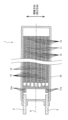
- FIG. 1 is a top view of an all-solid-state battery according to a first embodiment of the invention.
- FIG. 2 is a structural cross-sectional view of a battery cell according to the first embodiment of the present invention.
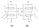
- FIG. 3 is a diagram comparing before and after expansion of a battery cell according to a comparative example.
- FIG. 4 is a diagram comparing before and after expansion of the battery cell according to the first embodiment of the present invention.
- FIG. 5 is a structural cross-sectional view of a battery cell according to a modification of the first embodiment of the present invention.
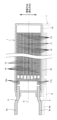
- FIG. 6 is a side view of an all-solid-state battery according to a second embodiment of the invention.
- FIG. 7 is a structural diagram of a battery cell according to the second embodiment of the present invention.
- FIG. 1 is a top view of the all-solid-state battery 100 of the first embodiment.
- FIG. 2 is a structural sectional view of the battery cell 1. As shown in FIG.
- the all-solid-state battery 100 of this embodiment is a secondary battery that can be charged and discharged multiple times.
- an all-solid-state battery 100 will be described as an example of a secondary battery.
- a semi-solid battery or one using an organic solvent (electrolytic solution) as an electrolyte may be used.
- the all-solid-state battery 100 includes a plurality of battery modules M provided in a housing (not shown) and configured by stacking a plurality of battery cells 1, and a battery module M in the stacking direction of the battery cells 1.
- the other end of the plate is fixed, and when the battery cell 1 expands and contracts, a second plate 4 that can move along with the battery cell 1 and an external device (not shown) attached to the first plate 2 are electrically connected. and a second terminal 9 attached to the second plate 4 and electrically connected to an external device.
- the battery module M is fixed within the housing by fixing the first plate 2 to the housing (not shown).
- the plurality of stacked battery cells 1 are held in a state of being stacked between the first plate 2 and the second plate 4 and pressed by an elastic band (not shown) or the like.
- four guide rods 3 are provided to support the second plate 4 movably in the stacking direction of the battery cells 1 .
- the battery cell 1 of this embodiment is formed in a substantially rectangular shape in plan view (see FIG. 1).
- the electrode structure of the battery cell 1 shown in FIG. 2 is a so-called non-bipolar type (internal parallel connection type), but may be a bipolar type (internal series connection type).
- the shape of the battery cell 1 is not limited to a rectangular shape, and may be circular, elliptical, or any other shape.
- the battery cell 1 includes a positive electrode current collector 11 and a negative electrode current collector 12 that are alternately stacked, and a power generating element portion provided between the positive electrode current collector 11 and the negative electrode current collector 12 that are adjacent to each other in the stacking direction. , and a laminate material 10 that is a battery exterior material covering these.
- the power generation element section includes a positive electrode layer 13 , a solid electrolyte layer 14 and a negative electrode layer 15 .
- the battery cell 1 is configured by stacking a plurality of laminated structures in which a positive electrode current collector 11, a positive electrode layer 13, a solid electrolyte layer 14, a negative electrode layer 15, and a negative electrode current collector 12 are stacked. .
- the positive electrode current collector 11 and the negative electrode current collector 12 are formed in a rectangular thin plate shape, for example, from a metal material such as aluminum, nickel, iron, stainless steel, titanium, or copper.
- the positive electrode current collector 11 and the negative electrode current collector 12 respectively have flexible extraction electrodes 11a and 12a extending from one side forming an outer edge.
- the lead electrodes 11a and 12a are provided so as to protrude in the same direction in a direction orthogonal to the stacking direction of the battery cells 1 (height direction when the lead electrodes 11a and 12a are oriented vertically).
- a positive electrode tab 5 and a negative electrode tab 6 serving as rigid terminals are attached to the tips of the extraction electrodes 11a and 12a, respectively. Thereby, the positive electrode tab 5 and the negative electrode tab 6 are provided so as to protrude in the same direction perpendicular to the stacking direction of the battery cells 1 .
- the positive electrode layer 13 is arranged on both main surfaces of the positive electrode current collector 11 (only the main surface of the positive electrode current collector 11 facing the negative electrode current collector 12 at the end).
- the positive electrode layer 13 contains, as a positive electrode active material, a substance capable of releasing lithium ions during charging and intercalating lithium ions during discharging by utilizing an oxidation-reduction reaction.
- materials for the positive electrode active material include lithium-transition metal composite oxides such as LiMn2O4, LiCoO2, LiNiO2, Li(Ni--Mn--Co)O2 and those in which a portion of these transition metals are replaced with other elements. substances, lithium-transition metal phosphate compounds, lithium-transition metal sulfate compounds, and the like.
- the solid electrolyte layer 14 is a layer containing a solid electrolyte as a main component and interposed between the positive electrode layer 13 and the negative electrode layer 15 .
- solid electrolyte materials include sulfide solid electrolytes and oxide solid electrolytes, and sulfide solid electrolytes are preferred.
- Suitable sulfide solid electrolytes are, for example, LPS-based materials (eg, aldirodite (Li 6 PS 5 Cl)) and LGPS-based materials (eg, Li 10 GeP 2 S 12 ).
- the negative electrode layer 15 is arranged on both main surfaces of the negative electrode current collector 12 (only the surface of the negative electrode current collector 12 facing the positive electrode current collector 11 at the end).
- the negative electrode layer 15 contains at least lithium metal or a substance forming an alloy with lithium as a negative electrode active material.
- the expression that the negative electrode layer 15 contains lithium metal as a negative electrode active material means that a lithium metal foil or lithium metal particles are arranged on the main surface of the negative electrode current collector 12 , a lithium-transition metal composite oxide, a lithium- A case where lithium metal is deposited on the main surface of the negative electrode current collector 12 using a positive electrode containing a positive electrode active material such as a transition metal phosphate compound or a lithium-transition metal sulfate compound is included.
- the fact that the negative electrode layer 15 contains a substance forming an alloy with lithium as an active material means that the negative electrode layer 15 contains at least one substance selected from In, Al, Si and Sn.
- the lead-out electrode 11a of the positive electrode current collector 11 located on the outermost side in the thickness direction is provided on the same plane as the body portion of the lead-out electrode 11a. , and the positive electrode tab 5 is connected to the tip portion thereof.
- the lead electrode 11a of the other positive electrode current collector 11 is bent toward the lead electrode 11a of the outermost positive electrode current collector 11 and connected.
- the lead electrode 12a of the negative electrode current collector 12, which is located on the outermost side in the thickness direction, is provided on the same plane as the body portion of this lead electrode 12a, and the positive electrode tab 5 is connected to the tip portion thereof. Further, the lead-out electrode 12a of the other negative electrode current collector 12 is bent toward the lead-out electrode 12a of the outermost negative electrode current collector 12 and connected.
- the positive electrode tab 5 and the negative electrode tab 6 are provided on opposite sides of the center line O in the thickness direction of the battery cell 1 . Moreover, the positive electrode tab 5 and the negative electrode tab 6 are arranged to be shifted in the width direction of the battery cell 1 (see FIG. 1). Then, as described above, by connecting the positive electrode tab 5 and the negative electrode tab 6 to the outermost positive electrode current collector 11 and the negative electrode current collector 12, the positive electrode tab 5 and the negative electrode tab 6 are connected to the battery cell 1. It can be provided at a position near the end face in the thickness direction.
- positive electrode tabs 5 and negative electrode tabs 6 of adjacent battery cells 1 are arranged to face each other, and are electrically connected via bus bars 7 . connected to The positive electrode tab 5 and the busbar 7, and the negative electrode tab 6 and the busbar 7 are connected by welding or the like.
- the plurality of battery cells 1 are electrically connected in series.
- the positive electrode tab 5 and the negative electrode tab 6 located at both ends of the stacked battery cells 1 are arranged to face the first terminal 8 and the second terminal 9 provided on the first plate 2 and the second plate 4, respectively. , and electrically connected to the first terminal 8 and the second terminal 9 via the bus bar 7 .
- the all-solid-state battery 100 contains at least lithium metal or a substance that forms an alloy with lithium as the negative electrode active material, the battery cells 1 expand and contract in the stacking direction as lithium ions are absorbed and released during charging and discharging. do.
- a change in the distance between the positive electrode tab 5 and the negative electrode tab 6 of the adjacent battery cells 1 when the battery cells 1 expand will be described with reference to FIGS. 3 and 4.
- FIG. 3A shows the battery cell 101 before expansion in the comparative example
- FIG. 3B shows the battery cell 101 after expansion in the comparative example.
- FIG. 4A shows the battery cell 1 before expansion of the battery cell 1 in this embodiment
- FIG. 4B shows the battery cell 1 after expansion in this embodiment.
- the bus-bar 7 is not illustrated for description.
- the distance between the positive electrode tab 5 and the negative electrode tab 6 increases from L1 to L2 when the battery cell 1 expands.
- the difference between the distances L1 and L2 corresponds to the amount of expansion in the region S1 between the positive electrode tabs 5 and the negative electrode tabs 6 of the adjacent battery cells 1 .
- the positive electrode tab 5 and the negative electrode tab 6 are provided on opposite sides of the battery cell 1 with respect to the center line O in the thickness direction. They are arranged to face each other. As a result, as shown in FIG. 4, the distance L (area S) between the positive electrode tabs 5 and the negative electrode tabs 6 in the adjacent battery cells 1 can be shortened. The amount of change in the distance from the negative electrode tab 6 (distance L3 - distance L) can be reduced.
- the battery module M as shown in FIG.
- the positive electrode tab 5 and the negative electrode tab 6 are laminated so as to face each other.
- the amount of change in the distance L between the positive electrode tab 5 and the negative electrode tab 6 can be reduced.
- the stress acting on Therefore according to the all-solid-state battery 100 of the present embodiment, it is possible to prevent damage to the connecting portion between the positive electrode tab 5 and the negative electrode tab 6 of the adjacent battery cells 1 .
- the positive electrode tab 5 and the negative electrode tab 6 are connected via the busbar 7, but the busbar 7 does not necessarily have to be provided.
- the positive electrode tab 5 and the negative electrode tab 6 are bent so that the connection portions 5a and 6a of the positive electrode tab 5 and the negative electrode tab 6 are positioned on the end faces in the stacking direction of the battery cell 1, respectively. You may make it form.
- the connection portion 5a of the positive electrode tab 5 and the connection portion 6a of the negative electrode tab 6 of the adjacent battery cells 1 can be directly connected.
- the cost can be reduced, and the number of connection parts such as welding can be reduced, so that the performance and reliability of the all-solid-state battery 100 (battery module M) are improved. can be made
- the all-solid-state battery 100 according to the first embodiment described above has the following effects.
- the positive electrode tab 5 and the negative electrode tab 6 are provided on opposite sides of the center line O in the thickness direction of the battery cell 1. Further, the positive electrode tabs 5 and the negative electrode tabs 6 of adjacent battery cells 1 are arranged and connected so as to face each other. As a result, when the battery cell 1 expands, the amount of change in the distance between the positive electrode tab 5 and the negative electrode tab 6 can be reduced. Stress can be reduced. As a result, it is possible to prevent the connecting portion between the positive electrode tab 5 and the negative electrode tab 6 from being damaged, thereby preventing the performance and reliability of the all-solid-state battery 100 from deteriorating.
- the positive electrode tab 5 and the negative electrode tab 6 are provided so as to protrude in the same direction perpendicular to the stacking direction of the battery cells 1.
- electrical connections are concentrated on one surface of the all-solid-state battery 100, which facilitates wiring work and maintenance.
- the positive electrode tab 5 and the negative electrode tab 6 located at both ends of the battery module M are connected to the first terminal 8 and the second terminal 9 provided on the first plate 2 and the second plate 4, respectively. are electrically connected via For example, when the positive electrode tab 5 or the negative electrode tab 6 of the battery cell 1 positioned closest to the second plate 4 is connected to the second terminal 9 provided on the first plate 2, all the stacked battery cells 1 The amount of change due to the expansion and contraction of the will act on the connecting portion between them.
- FIG. 6 is a side view of the all-solid-state battery 200 according to the second embodiment.
- FIG. 7 is a structural cross-sectional view of a battery cell 201 according to the second embodiment.
- the positive electrode tab 5 and the negative electrode tab 6 are provided so as to protrude in the same direction perpendicular to the stacking direction of the battery cell 1, whereas in the battery cell 1 according to the second embodiment.
- 201 is different in that the positive electrode tab 5 and the negative electrode tab 6 are provided so as to protrude in opposite directions to the direction orthogonal to the stacking direction of the battery cells 1 .
- the positive electrode tab 5 and the negative electrode tab 6 are provided on opposite sides of the center line O in the thickness direction of the battery cell 1 .
- the positive electrode tab 5 and the negative electrode tab 6 are provided so as to protrude in mutually opposite directions in a direction orthogonal to the stacking direction.
- the extraction electrode 11a of the positive electrode current collector 11 located on the outermost side is provided on the same plane as the body portion of the extraction electrode 11a, and the tip thereof A positive electrode tab 5 is connected to the portion.
- the lead electrode 11a of the other positive electrode current collector 11 is bent toward the lead electrode 11a of the outermost positive electrode current collector 11 and connected.
- the lead-out electrode 12a of the negative electrode current collector 12 located at the outermost side is provided on the same plane as the body portion of the lead-out electrode 12a, and the negative electrode tab 6 is connected to the tip portion thereof. Further, the lead-out electrode 12a of the other negative electrode current collector 12 is bent toward the lead-out electrode 12a of the outermost negative electrode current collector 12 and connected.
- the positive electrode tabs 5 and negative electrode tabs 6 of adjacent battery cells 201 are arranged to face each other and are electrically connected via the busbar 7 . Connected.
- the positive electrode tab 5 and the busbar 7, and the negative electrode tab 6 and the busbar 7 are connected by welding or the like.
- the plurality of battery cells 201 are electrically connected in series.
- the positive electrode tab 5 and the negative electrode tab 6 located at both ends of the stacked battery cells 201 are arranged to face the first terminal 8 and the second terminal 9 provided on the first plate 2 and the second plate 4, respectively. , and electrically connected to the first terminal 8 and the second terminal 9 via the bus bar 7 .
- the positive electrode tab 5 and the negative electrode tab 6 When provided in the center of the direction, the distance between the connecting portions of the positive electrode tab 5 and the negative electrode tab 6 can be increased compared to the all-solid-state battery 100 according to the first embodiment, so that the insulation can be improved. It is effective in that it can be reliably secured.
- the all-solid-state batteries 100 and 200 have been described as examples, but the present invention is not limited to this, and the present invention is not limited to this, and the battery cells expand and contract with charging and discharging, such as semi-solid batteries, specifically. It can be applied to any type of battery as long as it has a battery cell containing lithium metal or a lithium-containing alloy as a negative electrode active material in the negative electrode layer.
- the negative electrode layer 15 may be formed as a deposited layer on the surface facing the battery cell 11 and disappear when the battery cell 1 is discharged. Further, it may be a bipolar all-solid-state battery or semi-solid-state battery.
- the positive electrode tab 5 is connected to the first terminal 8 provided on the first plate 2 on the fixed side
- the negative electrode tab 6 is connected to the second terminal 9 provided on the second plate 4 on the movable side.
- the negative electrode tab 6 may be connected to the first terminal 8 and the positive electrode tab 5 may be connected to the second terminal 9 .
- the all-solid-state battery 100, 200 (secondary battery) has a battery module M configured by stacking a plurality of battery cells 1, 201 containing lithium metal or a lithium-containing alloy as a negative electrode active material in the negative electrode layer.
- the battery cell 1, 201 has a positive electrode tab 5 connected to the positive electrode current collector 11 and exposed to the outside, and a negative electrode tab 6 connected to the negative electrode current collector 12 and exposed to the outside.
- the positive electrode tab 5 and the negative electrode tab 6 are provided on opposite sides of the center line O in the thickness direction of the battery cell 1, 201, and the positive electrode tab 5 and the negative electrode tab 6 of the adjacent battery cells 1, 201 face each other. arranged and connected to
- the positive electrode tab 5 and the negative electrode tab 6 are provided so as to protrude in the same direction perpendicular to the stacking direction of the battery cells 1 .
- the positive electrode tab 5 and the negative electrode tab 6 are provided so as to protrude in opposite directions in the direction orthogonal to the stacking direction of the battery cells 201 .
- the distance between the connection portions of the positive electrode tab 5 and the negative electrode tab 6 is equal to the positive electrode tab 5 and the negative electrode tab 6. , projecting in the same direction perpendicular to the stacking direction of the battery cells 1 . Thereby, the insulation can be ensured more reliably.
- the battery cell 1, 201 includes a laminated positive electrode collector 11, a positive electrode layer 13, a solid electrolyte layer 14 (electrolyte layer), and a negative electrode collector 12 laminated. It is configured by stacking a plurality of laminated structures.
- the positive electrode tab 5 and the negative electrode tab 6 are connected to the positive electrode current collector 11 and the negative electrode current collector 12 positioned on the outermost side in the stacking direction of the battery cells 1 and 201 .
- the positive electrode tab 5 and the negative electrode tab 6 are positioned on the outermost side in the stacking direction of the battery cells 1, 201, so the distance between the positive electrode tab 5 and the negative electrode tab 6 of the adjacent battery cells 1, 201 is can be shortened.
- the battery cells 1, 201 are bipolar battery cells.
- the all-solid-state batteries 100 and 200 (secondary batteries) have a first terminal 8 and a second terminal 9 electrically connected to an external device, and one end of the battery module M in the stacking direction of the battery cells 1 and 201 are fixed. and the other end of the battery module M in the stacking direction of the battery cells 1, 201 are fixed, and when the battery cells 1, 201 expand and contract, they are aligned with the battery cells 1, 201. and a movable second plate 4 .
- the first terminal 8 is provided on the first plate 2 and, among the positive electrode tabs 5 and the negative electrode tabs 6 provided on the plurality of battery cells 1 and 201, the positive electrode tab 5 or the negative electrode tab 5 positioned closest to the first plate 2 side.
- the second terminal 9 connected to the tab 6 is provided on the second plate 4 and positioned closest to the second plate 4 among the positive electrode tabs 5 and negative electrode tabs 6 provided on the plurality of battery cells 1 and 201. connected to the positive electrode tab 5 or the negative electrode tab 6.
- the voltage between the second terminal 9 provided on the second plate 4 on the movable side and the positive electrode tab 5 or the negative electrode tab 6 connected to the second terminal 9 is increased. can reduce the amount of change in the distance of Thereby, the stress acting on the connection portion between the second terminal 9 and the positive electrode tab 5 or the negative electrode tab 6 connected to the second terminal 9 can be reduced. Therefore, the connection portion between the second terminal 9 and the positive electrode tab 5 or the negative electrode tab 6 connected to the second terminal 9 is prevented from being damaged, and the performance and reliability of the all-solid-state battery 100, 200 (secondary battery) are improved. can be prevented from getting worse.
- the positive electrode tab 5 and the negative electrode tab 6 are configured to be connected to the positive electrode current collector 11 and the negative electrode current collector 12 positioned outermost in the stacking direction of the battery cells 1 and 201.
- the positive electrode current collector 11 and the negative electrode current collector 12 located on the outermost side may be connected to the positive electrode current collector 11 and the negative electrode current collector 12 located inside.
Landscapes
- Chemical & Material Sciences (AREA)
- Chemical Kinetics & Catalysis (AREA)
- Electrochemistry (AREA)
- General Chemical & Material Sciences (AREA)
- Engineering & Computer Science (AREA)
- Manufacturing & Machinery (AREA)
- Connection Of Batteries Or Terminals (AREA)
- Battery Mounting, Suspending (AREA)
Priority Applications (5)
| Application Number | Priority Date | Filing Date | Title |
|---|---|---|---|
| PCT/IB2021/000846 WO2023099931A1 (ja) | 2021-12-01 | 2021-12-01 | 二次電池 |
| JP2023564263A JP7806809B2 (ja) | 2021-12-01 | 2021-12-01 | 二次電池 |
| CN202180104645.8A CN118525395A (zh) | 2021-12-01 | 2021-12-01 | 二次电池 |
| EP21966289.7A EP4443582A4 (en) | 2021-12-01 | 2021-12-01 | Secondary battery |
| US18/715,477 US20250030135A1 (en) | 2021-12-01 | 2021-12-01 | Secondary Battery |
Applications Claiming Priority (1)
| Application Number | Priority Date | Filing Date | Title |
|---|---|---|---|
| PCT/IB2021/000846 WO2023099931A1 (ja) | 2021-12-01 | 2021-12-01 | 二次電池 |
Publications (1)
| Publication Number | Publication Date |
|---|---|
| WO2023099931A1 true WO2023099931A1 (ja) | 2023-06-08 |
Family
ID=86611590
Family Applications (1)
| Application Number | Title | Priority Date | Filing Date |
|---|---|---|---|
| PCT/IB2021/000846 Ceased WO2023099931A1 (ja) | 2021-12-01 | 2021-12-01 | 二次電池 |
Country Status (5)
| Country | Link |
|---|---|
| US (1) | US20250030135A1 (https=) |
| EP (1) | EP4443582A4 (https=) |
| JP (1) | JP7806809B2 (https=) |
| CN (1) | CN118525395A (https=) |
| WO (1) | WO2023099931A1 (https=) |
Cited By (1)
| Publication number | Priority date | Publication date | Assignee | Title |
|---|---|---|---|---|
| WO2025069883A1 (ja) * | 2023-09-28 | 2025-04-03 | 日立造船株式会社 | 全固体電池の製造方法 |
Citations (5)
| Publication number | Priority date | Publication date | Assignee | Title |
|---|---|---|---|---|
| JP2004031195A (ja) * | 2002-06-27 | 2004-01-29 | Nissan Motor Co Ltd | ラミネート電池および組電池 |
| JP2011129675A (ja) * | 2009-12-17 | 2011-06-30 | Ud Trucks Corp | 蓄電デバイスおよび蓄電モジュール |
| JP2016515291A (ja) * | 2013-03-14 | 2016-05-26 | エネヴェート・コーポレーション | 電気化学セルスタックのためのクランプ装置 |
| JP2018088333A (ja) * | 2016-11-28 | 2018-06-07 | トヨタ自動車株式会社 | 直列接続用のラミネート型電池、及び組電池 |
| JP2019185976A (ja) | 2018-04-06 | 2019-10-24 | トヨタ自動車株式会社 | 電池システム |
Family Cites Families (5)
| Publication number | Priority date | Publication date | Assignee | Title |
|---|---|---|---|---|
| DE102009011524A1 (de) * | 2009-03-03 | 2010-09-09 | Li-Tec Battery Gmbh | Elektroenergie-Speicherzelle und Zellblock, Elektroenergie-Speichervorrichtung und Fahrzeug damit |
| JP2018041818A (ja) * | 2016-09-07 | 2018-03-15 | 株式会社フジクラ | 蓄電デバイス、蓄電モジュール、及び、蓄電モジュールの製造方法 |
| US11271243B2 (en) * | 2017-12-18 | 2022-03-08 | Samsung Electronics Co., Ltd. | All-solid secondary battery |
| JP7065600B2 (ja) | 2017-12-28 | 2022-05-12 | 積水化学工業株式会社 | リチウムイオン二次電池 |
| JP7093840B2 (ja) * | 2018-08-31 | 2022-06-30 | シャープ株式会社 | 金属空気電池モジュール |
-
2021
- 2021-12-01 WO PCT/IB2021/000846 patent/WO2023099931A1/ja not_active Ceased
- 2021-12-01 US US18/715,477 patent/US20250030135A1/en active Pending
- 2021-12-01 CN CN202180104645.8A patent/CN118525395A/zh active Pending
- 2021-12-01 JP JP2023564263A patent/JP7806809B2/ja active Active
- 2021-12-01 EP EP21966289.7A patent/EP4443582A4/en active Pending
Patent Citations (5)
| Publication number | Priority date | Publication date | Assignee | Title |
|---|---|---|---|---|
| JP2004031195A (ja) * | 2002-06-27 | 2004-01-29 | Nissan Motor Co Ltd | ラミネート電池および組電池 |
| JP2011129675A (ja) * | 2009-12-17 | 2011-06-30 | Ud Trucks Corp | 蓄電デバイスおよび蓄電モジュール |
| JP2016515291A (ja) * | 2013-03-14 | 2016-05-26 | エネヴェート・コーポレーション | 電気化学セルスタックのためのクランプ装置 |
| JP2018088333A (ja) * | 2016-11-28 | 2018-06-07 | トヨタ自動車株式会社 | 直列接続用のラミネート型電池、及び組電池 |
| JP2019185976A (ja) | 2018-04-06 | 2019-10-24 | トヨタ自動車株式会社 | 電池システム |
Non-Patent Citations (1)
| Title |
|---|
| See also references of EP4443582A4 |
Cited By (1)
| Publication number | Priority date | Publication date | Assignee | Title |
|---|---|---|---|---|
| WO2025069883A1 (ja) * | 2023-09-28 | 2025-04-03 | 日立造船株式会社 | 全固体電池の製造方法 |
Also Published As
| Publication number | Publication date |
|---|---|
| EP4443582A4 (en) | 2024-12-18 |
| CN118525395A (zh) | 2024-08-20 |
| JP7806809B2 (ja) | 2026-01-27 |
| EP4443582A1 (en) | 2024-10-09 |
| JPWO2023099931A1 (https=) | 2023-06-08 |
| US20250030135A1 (en) | 2025-01-23 |
Similar Documents
| Publication | Publication Date | Title |
|---|---|---|
| US8974954B2 (en) | Battery | |
| US20230121494A1 (en) | Electrode assembly for battery and battery | |
| KR101147207B1 (ko) | 전극군과 이를 적용한 이차 전지 | |
| US20130101878A1 (en) | Battery comprising cuboid cells which contain a bipolar electrode | |
| JP7264077B2 (ja) | 全固体電池 | |
| JP5624507B2 (ja) | 組電池 | |
| JP7806809B2 (ja) | 二次電池 | |
| US20240097266A1 (en) | Battery assembly and method therefor | |
| KR101476523B1 (ko) | 2차 전지의 전극 | |
| JP5429304B2 (ja) | 固体電池モジュール | |
| JP7775876B2 (ja) | 電池 | |
| JP2021099949A (ja) | 全固体電池 | |
| JP2023082486A (ja) | 二次電池 | |
| WO2024062777A1 (ja) | 電池およびその製造方法 | |
| JP5093666B2 (ja) | リチウム電池 | |
| JPWO2023099931A5 (https=) | ||
| JP2019192371A (ja) | 積層電池の製造方法 | |
| US20250202074A1 (en) | Battery | |
| US20250385404A1 (en) | Secondary battery | |
| US20240079657A1 (en) | Solid-state battery | |
| US20250149744A1 (en) | Assembled-battery structure and composite assembled-battery structure | |
| US20240332755A1 (en) | Battery module | |
| US20230163364A1 (en) | All-solid-state battery and method for producing it | |
| JP2025077154A (ja) | 電池 | |
| JP2012221688A (ja) | 積層電池 |
Legal Events
| Date | Code | Title | Description |
|---|---|---|---|
| 121 | Ep: the epo has been informed by wipo that ep was designated in this application |
Ref document number: 21966289 Country of ref document: EP Kind code of ref document: A1 |
|
| ENP | Entry into the national phase |
Ref document number: 2023564263 Country of ref document: JP Kind code of ref document: A |
|
| WWE | Wipo information: entry into national phase |
Ref document number: 202180104645.8 Country of ref document: CN Ref document number: 18715477 Country of ref document: US |
|
| NENP | Non-entry into the national phase |
Ref country code: DE |
|
| ENP | Entry into the national phase |
Ref document number: 2021966289 Country of ref document: EP Effective date: 20240701 |