WO2023095747A1 - 着色樹脂粒子及び調光積層体 - Google Patents
着色樹脂粒子及び調光積層体 Download PDFInfo
- Publication number
- WO2023095747A1 WO2023095747A1 PCT/JP2022/043023 JP2022043023W WO2023095747A1 WO 2023095747 A1 WO2023095747 A1 WO 2023095747A1 JP 2022043023 W JP2022043023 W JP 2022043023W WO 2023095747 A1 WO2023095747 A1 WO 2023095747A1
- Authority
- WO
- WIPO (PCT)
- Prior art keywords
- resin particles
- colored resin
- light
- less
- particles
- Prior art date
Links
- 239000002245 particle Substances 0.000 title claims abstract description 395
- 229920005989 resin Polymers 0.000 title claims abstract description 303
- 239000011347 resin Substances 0.000 title claims abstract description 303
- 239000000463 material Substances 0.000 claims abstract description 99
- 239000003086 colorant Substances 0.000 claims abstract description 39
- 239000000049 pigment Substances 0.000 claims description 50
- -1 acrylate compound Chemical class 0.000 claims description 49
- 125000006850 spacer group Chemical group 0.000 claims description 17
- 229910052700 potassium Inorganic materials 0.000 claims description 13
- 239000006229 carbon black Substances 0.000 claims description 9
- RTAQQCXQSZGOHL-UHFFFAOYSA-N Titanium Chemical compound [Ti] RTAQQCXQSZGOHL-UHFFFAOYSA-N 0.000 claims description 8
- 239000010936 titanium Substances 0.000 claims description 8
- 229910052719 titanium Inorganic materials 0.000 claims description 8
- 230000005484 gravity Effects 0.000 claims description 7
- 238000004040 coloring Methods 0.000 claims 1
- 239000002585 base Substances 0.000 description 50
- 239000000758 substrate Substances 0.000 description 47
- 239000004973 liquid crystal related substance Substances 0.000 description 39
- NIXOWILDQLNWCW-UHFFFAOYSA-M Acrylate Chemical compound [O-]C(=O)C=C NIXOWILDQLNWCW-UHFFFAOYSA-M 0.000 description 33
- 238000000034 method Methods 0.000 description 33
- 239000000178 monomer Substances 0.000 description 31
- 239000011230 binding agent Substances 0.000 description 19
- 239000011159 matrix material Substances 0.000 description 18
- 229920001577 copolymer Polymers 0.000 description 17
- 230000005684 electric field Effects 0.000 description 17
- 229920000642 polymer Polymers 0.000 description 16
- 239000004983 Polymer Dispersed Liquid Crystal Substances 0.000 description 15
- 230000000052 comparative effect Effects 0.000 description 15
- 239000011521 glass Substances 0.000 description 15
- 239000000725 suspension Substances 0.000 description 14
- 238000005259 measurement Methods 0.000 description 13
- MYRTYDVEIRVNKP-UHFFFAOYSA-N 1,2-Divinylbenzene Chemical compound C=CC1=CC=CC=C1C=C MYRTYDVEIRVNKP-UHFFFAOYSA-N 0.000 description 10
- 239000002775 capsule Substances 0.000 description 10
- 239000000523 sample Substances 0.000 description 10
- 238000002834 transmittance Methods 0.000 description 10
- PEDCQBHIVMGVHV-UHFFFAOYSA-N Glycerine Chemical compound OCC(O)CO PEDCQBHIVMGVHV-UHFFFAOYSA-N 0.000 description 9
- CQEYYJKEWSMYFG-UHFFFAOYSA-N butyl acrylate Chemical compound CCCCOC(=O)C=C CQEYYJKEWSMYFG-UHFFFAOYSA-N 0.000 description 9
- 239000002612 dispersion medium Substances 0.000 description 9
- 239000000203 mixture Substances 0.000 description 9
- LYCAIKOWRPUZTN-UHFFFAOYSA-N ethylene glycol Natural products OCCO LYCAIKOWRPUZTN-UHFFFAOYSA-N 0.000 description 7
- 238000005192 partition Methods 0.000 description 7
- 230000006378 damage Effects 0.000 description 6
- 239000000975 dye Substances 0.000 description 6
- 239000000126 substance Substances 0.000 description 6
- 239000005357 flat glass Substances 0.000 description 5
- 125000001153 fluoro group Chemical group F* 0.000 description 5
- 125000002887 hydroxy group Chemical group [H]O* 0.000 description 5
- WGCNASOHLSPBMP-UHFFFAOYSA-N hydroxyacetaldehyde Natural products OCC=O WGCNASOHLSPBMP-UHFFFAOYSA-N 0.000 description 5
- 230000000379 polymerizing effect Effects 0.000 description 5
- 230000001629 suppression Effects 0.000 description 5
- TXBCBTDQIULDIA-UHFFFAOYSA-N 2-[[3-hydroxy-2,2-bis(hydroxymethyl)propoxy]methyl]-2-(hydroxymethyl)propane-1,3-diol Chemical compound OCC(CO)(CO)COCC(CO)(CO)CO TXBCBTDQIULDIA-UHFFFAOYSA-N 0.000 description 4
- RRHGJUQNOFWUDK-UHFFFAOYSA-N Isoprene Chemical compound CC(=C)C=C RRHGJUQNOFWUDK-UHFFFAOYSA-N 0.000 description 4
- 239000004988 Nematic liquid crystal Substances 0.000 description 4
- PPBRXRYQALVLMV-UHFFFAOYSA-N Styrene Chemical compound C=CC1=CC=CC=C1 PPBRXRYQALVLMV-UHFFFAOYSA-N 0.000 description 4
- 150000001252 acrylic acid derivatives Chemical class 0.000 description 4
- 238000000149 argon plasma sintering Methods 0.000 description 4
- 239000003795 chemical substances by application Substances 0.000 description 4
- 239000003431 cross linking reagent Substances 0.000 description 4
- ZUOUZKKEUPVFJK-UHFFFAOYSA-N diphenyl Chemical compound C1=CC=CC=C1C1=CC=CC=C1 ZUOUZKKEUPVFJK-UHFFFAOYSA-N 0.000 description 4
- 238000009826 distribution Methods 0.000 description 4
- 239000010954 inorganic particle Substances 0.000 description 4
- 238000006116 polymerization reaction Methods 0.000 description 4
- BBEAQIROQSPTKN-UHFFFAOYSA-N pyrene Chemical compound C1=CC=C2C=CC3=CC=CC4=CC=C1C2=C43 BBEAQIROQSPTKN-UHFFFAOYSA-N 0.000 description 4
- 229920002545 silicone oil Polymers 0.000 description 4
- 239000004925 Acrylic resin Substances 0.000 description 3
- 229920000178 Acrylic resin Polymers 0.000 description 3
- 239000004986 Cholesteric liquid crystals (ChLC) Substances 0.000 description 3
- CERQOIWHTDAKMF-UHFFFAOYSA-N Methacrylic acid Chemical compound CC(=C)C(O)=O CERQOIWHTDAKMF-UHFFFAOYSA-N 0.000 description 3
- 239000004642 Polyimide Substances 0.000 description 3
- 239000002262 Schiff base Substances 0.000 description 3
- 150000004753 Schiff bases Chemical class 0.000 description 3
- NIXOWILDQLNWCW-UHFFFAOYSA-N acrylic acid group Chemical group C(C=C)(=O)O NIXOWILDQLNWCW-UHFFFAOYSA-N 0.000 description 3
- 235000010290 biphenyl Nutrition 0.000 description 3
- 150000001875 compounds Chemical class 0.000 description 3
- 230000003750 conditioning effect Effects 0.000 description 3
- AMGQUBHHOARCQH-UHFFFAOYSA-N indium;oxotin Chemical compound [In].[Sn]=O AMGQUBHHOARCQH-UHFFFAOYSA-N 0.000 description 3
- 239000003999 initiator Substances 0.000 description 3
- 239000007788 liquid Substances 0.000 description 3
- 238000004519 manufacturing process Methods 0.000 description 3
- PXHVJJICTQNCMI-UHFFFAOYSA-N nickel Substances [Ni] PXHVJJICTQNCMI-UHFFFAOYSA-N 0.000 description 3
- 230000003287 optical effect Effects 0.000 description 3
- 239000012860 organic pigment Substances 0.000 description 3
- 229920000139 polyethylene terephthalate Polymers 0.000 description 3
- 239000005020 polyethylene terephthalate Substances 0.000 description 3
- 229920001721 polyimide Polymers 0.000 description 3
- 238000010526 radical polymerization reaction Methods 0.000 description 3
- 229910000077 silane Inorganic materials 0.000 description 3
- 239000002904 solvent Substances 0.000 description 3
- 125000000391 vinyl group Chemical group [H]C([*])=C([H])[H] 0.000 description 3
- DMDRBXCDTZRMHZ-UHFFFAOYSA-N 1,4-bis(2,4,6-trimethylanilino)anthracene-9,10-dione Chemical compound CC1=CC(C)=CC(C)=C1NC(C=1C(=O)C2=CC=CC=C2C(=O)C=11)=CC=C1NC1=C(C)C=C(C)C=C1C DMDRBXCDTZRMHZ-UHFFFAOYSA-N 0.000 description 2
- IBABXJRXGSAJLQ-UHFFFAOYSA-N 1,4-bis(2,6-diethyl-4-methylanilino)anthracene-9,10-dione Chemical compound CCC1=CC(C)=CC(CC)=C1NC(C=1C(=O)C2=CC=CC=C2C(=O)C=11)=CC=C1NC1=C(CC)C=C(C)C=C1CC IBABXJRXGSAJLQ-UHFFFAOYSA-N 0.000 description 2
- MWZJGRDWJVHRDV-UHFFFAOYSA-N 1,4-bis(ethenoxy)butane Chemical compound C=COCCCCOC=C MWZJGRDWJVHRDV-UHFFFAOYSA-N 0.000 description 2
- QTKPMCIBUROOGY-UHFFFAOYSA-N 2,2,2-trifluoroethyl 2-methylprop-2-enoate Chemical compound CC(=C)C(=O)OCC(F)(F)F QTKPMCIBUROOGY-UHFFFAOYSA-N 0.000 description 2
- ALXCWDABTQQKAH-UHFFFAOYSA-N 4-(1-amino-4-hydroxy-9,10-dioxoanthracen-2-yl)oxy-n-(3-ethoxypropyl)benzenesulfonamide Chemical compound C1=CC(S(=O)(=O)NCCCOCC)=CC=C1OC1=CC(O)=C(C(=O)C=2C(=CC=CC=2)C2=O)C2=C1N ALXCWDABTQQKAH-UHFFFAOYSA-N 0.000 description 2
- CSCPPACGZOOCGX-UHFFFAOYSA-N Acetone Chemical compound CC(C)=O CSCPPACGZOOCGX-UHFFFAOYSA-N 0.000 description 2
- 229920002799 BoPET Polymers 0.000 description 2
- 230000005653 Brownian motion process Effects 0.000 description 2
- KAKZBPTYRLMSJV-UHFFFAOYSA-N Butadiene Chemical compound C=CC=C KAKZBPTYRLMSJV-UHFFFAOYSA-N 0.000 description 2
- VTYYLEPIZMXCLO-UHFFFAOYSA-L Calcium carbonate Chemical compound [Ca+2].[O-]C([O-])=O VTYYLEPIZMXCLO-UHFFFAOYSA-L 0.000 description 2
- OKTJSMMVPCPJKN-UHFFFAOYSA-N Carbon Chemical compound [C] OKTJSMMVPCPJKN-UHFFFAOYSA-N 0.000 description 2
- YCKRFDGAMUMZLT-UHFFFAOYSA-N Fluorine atom Chemical compound [F] YCKRFDGAMUMZLT-UHFFFAOYSA-N 0.000 description 2
- XEEYBQQBJWHFJM-UHFFFAOYSA-N Iron Chemical compound [Fe] XEEYBQQBJWHFJM-UHFFFAOYSA-N 0.000 description 2
- UQSXHKLRYXJYBZ-UHFFFAOYSA-N Iron oxide Chemical compound [Fe]=O UQSXHKLRYXJYBZ-UHFFFAOYSA-N 0.000 description 2
- 229920000877 Melamine resin Polymers 0.000 description 2
- 229920003171 Poly (ethylene oxide) Polymers 0.000 description 2
- 239000004952 Polyamide Substances 0.000 description 2
- 239000004743 Polypropylene Substances 0.000 description 2
- 239000004372 Polyvinyl alcohol Substances 0.000 description 2
- 229910004298 SiO 2 Inorganic materials 0.000 description 2
- VYPSYNLAJGMNEJ-UHFFFAOYSA-N Silicium dioxide Chemical compound O=[Si]=O VYPSYNLAJGMNEJ-UHFFFAOYSA-N 0.000 description 2
- XSQUKJJJFZCRTK-UHFFFAOYSA-N Urea Chemical compound NC(N)=O XSQUKJJJFZCRTK-UHFFFAOYSA-N 0.000 description 2
- 229920001807 Urea-formaldehyde Polymers 0.000 description 2
- XLOMVQKBTHCTTD-UHFFFAOYSA-N Zinc monoxide Chemical compound [Zn]=O XLOMVQKBTHCTTD-UHFFFAOYSA-N 0.000 description 2
- 239000000853 adhesive Substances 0.000 description 2
- 230000001070 adhesive effect Effects 0.000 description 2
- 239000002390 adhesive tape Substances 0.000 description 2
- 239000001000 anthraquinone dye Substances 0.000 description 2
- 239000000987 azo dye Substances 0.000 description 2
- AYJRCSIUFZENHW-UHFFFAOYSA-L barium carbonate Chemical compound [Ba+2].[O-]C([O-])=O AYJRCSIUFZENHW-UHFFFAOYSA-L 0.000 description 2
- 230000001588 bifunctional effect Effects 0.000 description 2
- 239000004305 biphenyl Substances 0.000 description 2
- 238000005537 brownian motion Methods 0.000 description 2
- WERYXYBDKMZEQL-UHFFFAOYSA-N butane-1,4-diol Chemical compound OCCCCO WERYXYBDKMZEQL-UHFFFAOYSA-N 0.000 description 2
- 238000004132 cross linking Methods 0.000 description 2
- 238000002845 discoloration Methods 0.000 description 2
- 239000002270 dispersing agent Substances 0.000 description 2
- 238000006073 displacement reaction Methods 0.000 description 2
- 238000002296 dynamic light scattering Methods 0.000 description 2
- 230000002708 enhancing effect Effects 0.000 description 2
- 239000003822 epoxy resin Substances 0.000 description 2
- FJKIXWOMBXYWOQ-UHFFFAOYSA-N ethenoxyethane Chemical compound CCOC=C FJKIXWOMBXYWOQ-UHFFFAOYSA-N 0.000 description 2
- MBGQQKKTDDNCSG-UHFFFAOYSA-N ethenyl-diethoxy-methylsilane Chemical compound CCO[Si](C)(C=C)OCC MBGQQKKTDDNCSG-UHFFFAOYSA-N 0.000 description 2
- ZLNAFSPCNATQPQ-UHFFFAOYSA-N ethenyl-dimethoxy-methylsilane Chemical compound CO[Si](C)(OC)C=C ZLNAFSPCNATQPQ-UHFFFAOYSA-N 0.000 description 2
- GVEPBJHOBDJJJI-UHFFFAOYSA-N fluoranthrene Natural products C1=CC(C2=CC=CC=C22)=C3C2=CC=CC3=C1 GVEPBJHOBDJJJI-UHFFFAOYSA-N 0.000 description 2
- 229910052731 fluorine Inorganic materials 0.000 description 2
- 239000011737 fluorine Substances 0.000 description 2
- LEQAOMBKQFMDFZ-UHFFFAOYSA-N glyoxal Chemical compound O=CC=O LEQAOMBKQFMDFZ-UHFFFAOYSA-N 0.000 description 2
- 229910052736 halogen Inorganic materials 0.000 description 2
- 150000002367 halogens Chemical class 0.000 description 2
- 238000009413 insulation Methods 0.000 description 2
- 229910052751 metal Inorganic materials 0.000 description 2
- 239000002184 metal Substances 0.000 description 2
- 229910052759 nickel Inorganic materials 0.000 description 2
- 229940059574 pentaerithrityl Drugs 0.000 description 2
- WXZMFSXDPGVJKK-UHFFFAOYSA-N pentaerythritol Chemical compound OCC(CO)(CO)CO WXZMFSXDPGVJKK-UHFFFAOYSA-N 0.000 description 2
- 125000002080 perylenyl group Chemical group C1(=CC=C2C=CC=C3C4=CC=CC5=CC=CC(C1=C23)=C45)* 0.000 description 2
- CSHWQDPOILHKBI-UHFFFAOYSA-N peryrene Natural products C1=CC(C2=CC=CC=3C2=C2C=CC=3)=C3C2=CC=CC3=C1 CSHWQDPOILHKBI-UHFFFAOYSA-N 0.000 description 2
- 238000005191 phase separation Methods 0.000 description 2
- IEQIEDJGQAUEQZ-UHFFFAOYSA-N phthalocyanine Chemical compound N1C(N=C2C3=CC=CC=C3C(N=C3C4=CC=CC=C4C(=N4)N3)=N2)=C(C=CC=C2)C2=C1N=C1C2=CC=CC=C2C4=N1 IEQIEDJGQAUEQZ-UHFFFAOYSA-N 0.000 description 2
- 229920002647 polyamide Polymers 0.000 description 2
- 238000006068 polycondensation reaction Methods 0.000 description 2
- 229920000647 polyepoxide Polymers 0.000 description 2
- 239000002861 polymer material Substances 0.000 description 2
- 229920001155 polypropylene Polymers 0.000 description 2
- 229920002451 polyvinyl alcohol Polymers 0.000 description 2
- 239000000843 powder Substances 0.000 description 2
- FYNROBRQIVCIQF-UHFFFAOYSA-N pyrrolo[3,2-b]pyrrole-5,6-dione Chemical compound C1=CN=C2C(=O)C(=O)N=C21 FYNROBRQIVCIQF-UHFFFAOYSA-N 0.000 description 2
- 239000007870 radical polymerization initiator Substances 0.000 description 2
- 239000000565 sealant Substances 0.000 description 2
- LJFWQNJLLOFIJK-UHFFFAOYSA-N solvent violet 13 Chemical compound C1=CC(C)=CC=C1NC1=CC=C(O)C2=C1C(=O)C1=CC=CC=C1C2=O LJFWQNJLLOFIJK-UHFFFAOYSA-N 0.000 description 2
- 238000004611 spectroscopical analysis Methods 0.000 description 2
- VZCYOOQTPOCHFL-UHFFFAOYSA-N trans-butenedioic acid Natural products OC(=O)C=CC(O)=O VZCYOOQTPOCHFL-UHFFFAOYSA-N 0.000 description 2
- AQRLNPVMDITEJU-UHFFFAOYSA-N triethylsilane Chemical compound CC[SiH](CC)CC AQRLNPVMDITEJU-UHFFFAOYSA-N 0.000 description 2
- XLYOFNOQVPJJNP-UHFFFAOYSA-N water Substances O XLYOFNOQVPJJNP-UHFFFAOYSA-N 0.000 description 2
- DTGKSKDOIYIVQL-WEDXCCLWSA-N (+)-borneol Chemical group C1C[C@@]2(C)[C@@H](O)C[C@@H]1C2(C)C DTGKSKDOIYIVQL-WEDXCCLWSA-N 0.000 description 1
- QNODIIQQMGDSEF-UHFFFAOYSA-N (1-hydroxycyclohexyl)-phenylmethanone Chemical compound C=1C=CC=CC=1C(=O)C1(O)CCCCC1 QNODIIQQMGDSEF-UHFFFAOYSA-N 0.000 description 1
- XWZOKATWICIEMU-UHFFFAOYSA-N (3,5-difluoro-4-formylphenyl)boronic acid Chemical compound OB(O)C1=CC(F)=C(C=O)C(F)=C1 XWZOKATWICIEMU-UHFFFAOYSA-N 0.000 description 1
- LTQBNYCMVZQRSD-UHFFFAOYSA-N (4-ethenylphenyl)-trimethoxysilane Chemical compound CO[Si](OC)(OC)C1=CC=C(C=C)C=C1 LTQBNYCMVZQRSD-UHFFFAOYSA-N 0.000 description 1
- QERNPKXJOBLNFM-UHFFFAOYSA-N 1,1,2,2,3,3,4,4-octafluoropentane Chemical compound CC(F)(F)C(F)(F)C(F)(F)C(F)F QERNPKXJOBLNFM-UHFFFAOYSA-N 0.000 description 1
- HIYIGPVBMDKPCR-UHFFFAOYSA-N 1,1-bis(ethenoxymethyl)cyclohexane Chemical compound C=COCC1(COC=C)CCCCC1 HIYIGPVBMDKPCR-UHFFFAOYSA-N 0.000 description 1
- MYWOJODOMFBVCB-UHFFFAOYSA-N 1,2,6-trimethylphenanthrene Chemical compound CC1=CC=C2C3=CC(C)=CC=C3C=CC2=C1C MYWOJODOMFBVCB-UHFFFAOYSA-N 0.000 description 1
- CHRJZRDFSQHIFI-UHFFFAOYSA-N 1,2-bis(ethenyl)benzene;styrene Chemical compound C=CC1=CC=CC=C1.C=CC1=CC=CC=C1C=C CHRJZRDFSQHIFI-UHFFFAOYSA-N 0.000 description 1
- RYHBNJHYFVUHQT-UHFFFAOYSA-N 1,4-Dioxane Chemical compound C1COCCO1 RYHBNJHYFVUHQT-UHFFFAOYSA-N 0.000 description 1
- CKBFYMOTEJMJTP-UHFFFAOYSA-N 1,5-bis(3-methylanilino)anthracene-9,10-dione Chemical compound CC1=CC=CC(NC=2C=3C(=O)C4=CC=CC(NC=5C=C(C)C=CC=5)=C4C(=O)C=3C=CC=2)=C1 CKBFYMOTEJMJTP-UHFFFAOYSA-N 0.000 description 1
- CNRPDCKHCGUKDK-UHFFFAOYSA-N 1,8-bis(phenylsulfanyl)anthracene-9,10-dione Chemical compound C=12C(=O)C3=C(SC=4C=CC=CC=4)C=CC=C3C(=O)C2=CC=CC=1SC1=CC=CC=C1 CNRPDCKHCGUKDK-UHFFFAOYSA-N 0.000 description 1
- UWFRVQVNYNPBEF-UHFFFAOYSA-N 1-(2,4-dimethylphenyl)propan-1-one Chemical compound CCC(=O)C1=CC=C(C)C=C1C UWFRVQVNYNPBEF-UHFFFAOYSA-N 0.000 description 1
- SAMJGBVVQUEMGC-UHFFFAOYSA-N 1-ethenoxy-2-(2-ethenoxyethoxy)ethane Chemical compound C=COCCOCCOC=C SAMJGBVVQUEMGC-UHFFFAOYSA-N 0.000 description 1
- OVGRCEFMXPHEBL-UHFFFAOYSA-N 1-ethenoxypropane Chemical compound CCCOC=C OVGRCEFMXPHEBL-UHFFFAOYSA-N 0.000 description 1
- NIDFGXDXQKPZMA-UHFFFAOYSA-N 14h-benz[4,5]isoquino[2,1-a]perimidin-14-one Chemical compound C1=CC(N2C(=O)C=3C4=C(C2=N2)C=CC=C4C=CC=3)=C3C2=CC=CC3=C1 NIDFGXDXQKPZMA-UHFFFAOYSA-N 0.000 description 1
- ZNJXRXXJPIFFAO-UHFFFAOYSA-N 2,2,3,3,4,4,5,5-octafluoropentyl 2-methylprop-2-enoate Chemical compound CC(=C)C(=O)OCC(F)(F)C(F)(F)C(F)(F)C(F)F ZNJXRXXJPIFFAO-UHFFFAOYSA-N 0.000 description 1
- VHJHZYSXJKREEE-UHFFFAOYSA-N 2,2,3,3-tetrafluoropropyl prop-2-enoate Chemical compound FC(F)C(F)(F)COC(=O)C=C VHJHZYSXJKREEE-UHFFFAOYSA-N 0.000 description 1
- KWVGIHKZDCUPEU-UHFFFAOYSA-N 2,2-dimethoxy-2-phenylacetophenone Chemical compound C=1C=CC=CC=1C(OC)(OC)C(=O)C1=CC=CC=C1 KWVGIHKZDCUPEU-UHFFFAOYSA-N 0.000 description 1
- FXNDIJDIPNCZQJ-UHFFFAOYSA-N 2,4,4-trimethylpent-1-ene Chemical group CC(=C)CC(C)(C)C FXNDIJDIPNCZQJ-UHFFFAOYSA-N 0.000 description 1
- SMZOUWXMTYCWNB-UHFFFAOYSA-N 2-(2-methoxy-5-methylphenyl)ethanamine Chemical compound COC1=CC=C(C)C=C1CCN SMZOUWXMTYCWNB-UHFFFAOYSA-N 0.000 description 1
- FWLHAQYOFMQTHQ-UHFFFAOYSA-N 2-N-[8-[[8-(4-aminoanilino)-10-phenylphenazin-10-ium-2-yl]amino]-10-phenylphenazin-10-ium-2-yl]-8-N,10-diphenylphenazin-10-ium-2,8-diamine hydroxy-oxido-dioxochromium Chemical compound O[Cr]([O-])(=O)=O.O[Cr]([O-])(=O)=O.O[Cr]([O-])(=O)=O.Nc1ccc(Nc2ccc3nc4ccc(Nc5ccc6nc7ccc(Nc8ccc9nc%10ccc(Nc%11ccccc%11)cc%10[n+](-c%10ccccc%10)c9c8)cc7[n+](-c7ccccc7)c6c5)cc4[n+](-c4ccccc4)c3c2)cc1 FWLHAQYOFMQTHQ-UHFFFAOYSA-N 0.000 description 1
- SBYMUDUGTIKLCR-UHFFFAOYSA-N 2-chloroethenylbenzene Chemical compound ClC=CC1=CC=CC=C1 SBYMUDUGTIKLCR-UHFFFAOYSA-N 0.000 description 1
- XMLYCEVDHLAQEL-UHFFFAOYSA-N 2-hydroxy-2-methyl-1-phenylpropan-1-one Chemical compound CC(C)(O)C(=O)C1=CC=CC=C1 XMLYCEVDHLAQEL-UHFFFAOYSA-N 0.000 description 1
- 125000000954 2-hydroxyethyl group Chemical group [H]C([*])([H])C([H])([H])O[H] 0.000 description 1
- GWZMWHWAWHPNHN-UHFFFAOYSA-N 2-hydroxypropyl prop-2-enoate Chemical compound CC(O)COC(=O)C=C GWZMWHWAWHPNHN-UHFFFAOYSA-N 0.000 description 1
- KXGFMDJXCMQABM-UHFFFAOYSA-N 2-methoxy-6-methylphenol Chemical compound [CH]OC1=CC=CC([CH])=C1O KXGFMDJXCMQABM-UHFFFAOYSA-N 0.000 description 1
- WLPATYNQCGVFFH-UHFFFAOYSA-N 2-phenylbenzonitrile Chemical group N#CC1=CC=CC=C1C1=CC=CC=C1 WLPATYNQCGVFFH-UHFFFAOYSA-N 0.000 description 1
- 125000003903 2-propenyl group Chemical group [H]C([*])([H])C([H])=C([H])[H] 0.000 description 1
- UBZVRROHBDDCQY-UHFFFAOYSA-N 20749-68-2 Chemical compound C1=CC(N2C(=O)C3=C(C(=C(Cl)C(Cl)=C3C2=N2)Cl)Cl)=C3C2=CC=CC3=C1 UBZVRROHBDDCQY-UHFFFAOYSA-N 0.000 description 1
- DOYKFSOCSXVQAN-UHFFFAOYSA-N 3-[diethoxy(methyl)silyl]propyl 2-methylprop-2-enoate Chemical compound CCO[Si](C)(OCC)CCCOC(=O)C(C)=C DOYKFSOCSXVQAN-UHFFFAOYSA-N 0.000 description 1
- LZMNXXQIQIHFGC-UHFFFAOYSA-N 3-[dimethoxy(methyl)silyl]propyl 2-methylprop-2-enoate Chemical compound CO[Si](C)(OC)CCCOC(=O)C(C)=C LZMNXXQIQIHFGC-UHFFFAOYSA-N 0.000 description 1
- ATVJXMYDOSMEPO-UHFFFAOYSA-N 3-prop-2-enoxyprop-1-ene Chemical compound C=CCOCC=C ATVJXMYDOSMEPO-UHFFFAOYSA-N 0.000 description 1
- URDOJQUSEUXVRP-UHFFFAOYSA-N 3-triethoxysilylpropyl 2-methylprop-2-enoate Chemical compound CCO[Si](OCC)(OCC)CCCOC(=O)C(C)=C URDOJQUSEUXVRP-UHFFFAOYSA-N 0.000 description 1
- XDLMVUHYZWKMMD-UHFFFAOYSA-N 3-trimethoxysilylpropyl 2-methylprop-2-enoate Chemical compound CO[Si](OC)(OC)CCCOC(=O)C(C)=C XDLMVUHYZWKMMD-UHFFFAOYSA-N 0.000 description 1
- KBQVDAIIQCXKPI-UHFFFAOYSA-N 3-trimethoxysilylpropyl prop-2-enoate Chemical compound CO[Si](OC)(OC)CCCOC(=O)C=C KBQVDAIIQCXKPI-UHFFFAOYSA-N 0.000 description 1
- YNWJPOVPFGCGLE-UHFFFAOYSA-N 4,4-diethoxybut-1-enylsilane Chemical compound C(C)OC(CC=C[SiH3])OCC YNWJPOVPFGCGLE-UHFFFAOYSA-N 0.000 description 1
- MZZPECHJKDVTOI-UHFFFAOYSA-N 4,4-dimethoxybut-1-enylsilane Chemical compound COC(CC=C[SiH3])OC MZZPECHJKDVTOI-UHFFFAOYSA-N 0.000 description 1
- QPQKUYVSJWQSDY-UHFFFAOYSA-N 4-phenyldiazenylaniline Chemical compound C1=CC(N)=CC=C1N=NC1=CC=CC=C1 QPQKUYVSJWQSDY-UHFFFAOYSA-N 0.000 description 1
- ZLQGITSKRNWIOT-UHFFFAOYSA-N 5-(dimethylamino)furan-2-carbaldehyde Chemical compound CN(C)C1=CC=C(C=O)O1 ZLQGITSKRNWIOT-UHFFFAOYSA-N 0.000 description 1
- FQLZTPSAVDHUKS-UHFFFAOYSA-N 6-amino-2-(2,4-dimethylphenyl)benzo[de]isoquinoline-1,3-dione Chemical compound CC1=CC(C)=CC=C1N(C1=O)C(=O)C2=C3C1=CC=CC3=C(N)C=C2 FQLZTPSAVDHUKS-UHFFFAOYSA-N 0.000 description 1
- GZVHEAJQGPRDLQ-UHFFFAOYSA-N 6-phenyl-1,3,5-triazine-2,4-diamine Chemical compound NC1=NC(N)=NC(C=2C=CC=CC=2)=N1 GZVHEAJQGPRDLQ-UHFFFAOYSA-N 0.000 description 1
- NLHHRLWOUZZQLW-UHFFFAOYSA-N Acrylonitrile Chemical compound C=CC#N NLHHRLWOUZZQLW-UHFFFAOYSA-N 0.000 description 1
- 239000005995 Aluminium silicate Substances 0.000 description 1
- 238000012935 Averaging Methods 0.000 description 1
- NOWKCMXCCJGMRR-UHFFFAOYSA-N Aziridine Chemical compound C1CN1 NOWKCMXCCJGMRR-UHFFFAOYSA-N 0.000 description 1
- LSNNMFCWUKXFEE-UHFFFAOYSA-M Bisulfite Chemical compound OS([O-])=O LSNNMFCWUKXFEE-UHFFFAOYSA-M 0.000 description 1
- BVKZGUZCCUSVTD-UHFFFAOYSA-L Carbonate Chemical compound [O-]C([O-])=O BVKZGUZCCUSVTD-UHFFFAOYSA-L 0.000 description 1
- VYZAMTAEIAYCRO-UHFFFAOYSA-N Chromium Chemical compound [Cr] VYZAMTAEIAYCRO-UHFFFAOYSA-N 0.000 description 1
- RYGMFSIKBFXOCR-UHFFFAOYSA-N Copper Chemical compound [Cu] RYGMFSIKBFXOCR-UHFFFAOYSA-N 0.000 description 1
- XDTMQSROBMDMFD-UHFFFAOYSA-N Cyclohexane Chemical compound C1CCCCC1 XDTMQSROBMDMFD-UHFFFAOYSA-N 0.000 description 1
- XMSXQFUHVRWGNA-UHFFFAOYSA-N Decamethylcyclopentasiloxane Chemical compound C[Si]1(C)O[Si](C)(C)O[Si](C)(C)O[Si](C)(C)O[Si](C)(C)O1 XMSXQFUHVRWGNA-UHFFFAOYSA-N 0.000 description 1
- 239000004641 Diallyl-phthalate Substances 0.000 description 1
- BRLQWZUYTZBJKN-UHFFFAOYSA-N Epichlorohydrin Chemical compound ClCC1CO1 BRLQWZUYTZBJKN-UHFFFAOYSA-N 0.000 description 1
- VGGSQFUCUMXWEO-UHFFFAOYSA-N Ethene Chemical compound C=C VGGSQFUCUMXWEO-UHFFFAOYSA-N 0.000 description 1
- 239000005977 Ethylene Substances 0.000 description 1
- VZCYOOQTPOCHFL-OWOJBTEDSA-N Fumaric acid Natural products OC(=O)\C=C\C(O)=O VZCYOOQTPOCHFL-OWOJBTEDSA-N 0.000 description 1
- 108010010803 Gelatin Proteins 0.000 description 1
- SXRSQZLOMIGNAQ-UHFFFAOYSA-N Glutaraldehyde Chemical compound O=CCCCC=O SXRSQZLOMIGNAQ-UHFFFAOYSA-N 0.000 description 1
- 235000000177 Indigofera tinctoria Nutrition 0.000 description 1
- SIKJAQJRHWYJAI-UHFFFAOYSA-N Indole Chemical compound C1=CC=C2NC=CC2=C1 SIKJAQJRHWYJAI-UHFFFAOYSA-N 0.000 description 1
- VQTUBCCKSQIDNK-UHFFFAOYSA-N Isobutene Chemical group CC(C)=C VQTUBCCKSQIDNK-UHFFFAOYSA-N 0.000 description 1
- FYYHWMGAXLPEAU-UHFFFAOYSA-N Magnesium Chemical compound [Mg] FYYHWMGAXLPEAU-UHFFFAOYSA-N 0.000 description 1
- 239000004640 Melamine resin Substances 0.000 description 1
- CERQOIWHTDAKMF-UHFFFAOYSA-M Methacrylate Chemical compound CC(=C)C([O-])=O CERQOIWHTDAKMF-UHFFFAOYSA-M 0.000 description 1
- 239000004696 Poly ether ether ketone Substances 0.000 description 1
- 229920002845 Poly(methacrylic acid) Polymers 0.000 description 1
- 229920002319 Poly(methyl acrylate) Polymers 0.000 description 1
- 229930182556 Polyacetal Natural products 0.000 description 1
- 239000004962 Polyamide-imide Substances 0.000 description 1
- 239000005062 Polybutadiene Substances 0.000 description 1
- 239000004695 Polyether sulfone Substances 0.000 description 1
- 239000004698 Polyethylene Substances 0.000 description 1
- 239000002202 Polyethylene glycol Substances 0.000 description 1
- 229920002367 Polyisobutene Polymers 0.000 description 1
- 239000004721 Polyphenylene oxide Substances 0.000 description 1
- 239000004793 Polystyrene Substances 0.000 description 1
- 229920001328 Polyvinylidene chloride Polymers 0.000 description 1
- OFOBLEOULBTSOW-UHFFFAOYSA-N Propanedioic acid Natural products OC(=O)CC(O)=O OFOBLEOULBTSOW-UHFFFAOYSA-N 0.000 description 1
- NRCMAYZCPIVABH-UHFFFAOYSA-N Quinacridone Chemical compound N1C2=CC=CC=C2C(=O)C2=C1C=C1C(=O)C3=CC=CC=C3NC1=C2 NRCMAYZCPIVABH-UHFFFAOYSA-N 0.000 description 1
- 229910052581 Si3N4 Inorganic materials 0.000 description 1
- BLRPTPMANUNPDV-UHFFFAOYSA-N Silane Chemical compound [SiH4] BLRPTPMANUNPDV-UHFFFAOYSA-N 0.000 description 1
- XUIMIQQOPSSXEZ-UHFFFAOYSA-N Silicon Chemical compound [Si] XUIMIQQOPSSXEZ-UHFFFAOYSA-N 0.000 description 1
- 239000004990 Smectic liquid crystal Substances 0.000 description 1
- 229910006404 SnO 2 Inorganic materials 0.000 description 1
- 229920002125 Sokalan® Polymers 0.000 description 1
- 229910000831 Steel Inorganic materials 0.000 description 1
- PJANXHGTPQOBST-VAWYXSNFSA-N Stilbene Natural products C=1C=CC=CC=1/C=C/C1=CC=CC=C1 PJANXHGTPQOBST-VAWYXSNFSA-N 0.000 description 1
- BOTDANWDWHJENH-UHFFFAOYSA-N Tetraethyl orthosilicate Chemical compound CCO[Si](OCC)(OCC)OCC BOTDANWDWHJENH-UHFFFAOYSA-N 0.000 description 1
- GWEVSGVZZGPLCZ-UHFFFAOYSA-N Titan oxide Chemical compound O=[Ti]=O GWEVSGVZZGPLCZ-UHFFFAOYSA-N 0.000 description 1
- NRTOMJZYCJJWKI-UHFFFAOYSA-N Titanium nitride Chemical compound [Ti]#N NRTOMJZYCJJWKI-UHFFFAOYSA-N 0.000 description 1
- ZJCCRDAZUWHFQH-UHFFFAOYSA-N Trimethylolpropane Chemical compound CCC(CO)(CO)CO ZJCCRDAZUWHFQH-UHFFFAOYSA-N 0.000 description 1
- XTXRWKRVRITETP-UHFFFAOYSA-N Vinyl acetate Chemical compound CC(=O)OC=C XTXRWKRVRITETP-UHFFFAOYSA-N 0.000 description 1
- BZHJMEDXRYGGRV-UHFFFAOYSA-N Vinyl chloride Chemical compound ClC=C BZHJMEDXRYGGRV-UHFFFAOYSA-N 0.000 description 1
- QYKIQEUNHZKYBP-UHFFFAOYSA-N Vinyl ether Chemical class C=COC=C QYKIQEUNHZKYBP-UHFFFAOYSA-N 0.000 description 1
- IWQPVKKGSBGBBS-UHFFFAOYSA-N [O]CC1CO1 Chemical group [O]CC1CO1 IWQPVKKGSBGBBS-UHFFFAOYSA-N 0.000 description 1
- RMKZLFMHXZAGTM-UHFFFAOYSA-N [dimethoxy(propyl)silyl]oxymethyl prop-2-enoate Chemical compound CCC[Si](OC)(OC)OCOC(=O)C=C RMKZLFMHXZAGTM-UHFFFAOYSA-N 0.000 description 1
- GUCYFKSBFREPBC-UHFFFAOYSA-N [phenyl-(2,4,6-trimethylbenzoyl)phosphoryl]-(2,4,6-trimethylphenyl)methanone Chemical compound CC1=CC(C)=CC(C)=C1C(=O)P(=O)(C=1C=CC=CC=1)C(=O)C1=C(C)C=C(C)C=C1C GUCYFKSBFREPBC-UHFFFAOYSA-N 0.000 description 1
- IKHGUXGNUITLKF-XPULMUKRSA-N acetaldehyde Chemical compound [14CH]([14CH3])=O IKHGUXGNUITLKF-XPULMUKRSA-N 0.000 description 1
- 239000002253 acid Substances 0.000 description 1
- 239000011149 active material Substances 0.000 description 1
- 239000000654 additive Substances 0.000 description 1
- IBVAQQYNSHJXBV-UHFFFAOYSA-N adipic acid dihydrazide Chemical compound NNC(=O)CCCCC(=O)NN IBVAQQYNSHJXBV-UHFFFAOYSA-N 0.000 description 1
- GZCGUPFRVQAUEE-SLPGGIOYSA-N aldehydo-D-glucose Chemical compound OC[C@@H](O)[C@@H](O)[C@H](O)[C@@H](O)C=O GZCGUPFRVQAUEE-SLPGGIOYSA-N 0.000 description 1
- 125000003342 alkenyl group Chemical group 0.000 description 1
- 125000000217 alkyl group Chemical group 0.000 description 1
- XYLMUPLGERFSHI-UHFFFAOYSA-N alpha-Methylstyrene Chemical compound CC(=C)C1=CC=CC=C1 XYLMUPLGERFSHI-UHFFFAOYSA-N 0.000 description 1
- 229910052782 aluminium Inorganic materials 0.000 description 1
- XAGFODPZIPBFFR-UHFFFAOYSA-N aluminium Chemical compound [Al] XAGFODPZIPBFFR-UHFFFAOYSA-N 0.000 description 1
- WNROFYMDJYEPJX-UHFFFAOYSA-K aluminium hydroxide Chemical compound [OH-].[OH-].[OH-].[Al+3] WNROFYMDJYEPJX-UHFFFAOYSA-K 0.000 description 1
- PNEYBMLMFCGWSK-UHFFFAOYSA-N aluminium oxide Inorganic materials [O-2].[O-2].[O-2].[Al+3].[Al+3] PNEYBMLMFCGWSK-UHFFFAOYSA-N 0.000 description 1
- 235000011126 aluminium potassium sulphate Nutrition 0.000 description 1
- 235000012211 aluminium silicate Nutrition 0.000 description 1
- PGEHNUUBUQTUJB-UHFFFAOYSA-N anthanthrone Chemical compound C1=CC=C2C(=O)C3=CC=C4C=CC=C5C(=O)C6=CC=C1C2=C6C3=C54 PGEHNUUBUQTUJB-UHFFFAOYSA-N 0.000 description 1
- PYKYMHQGRFAEBM-UHFFFAOYSA-N anthraquinone Natural products CCC(=O)c1c(O)c2C(=O)C3C(C=CC=C3O)C(=O)c2cc1CC(=O)OC PYKYMHQGRFAEBM-UHFFFAOYSA-N 0.000 description 1
- 150000004056 anthraquinones Chemical class 0.000 description 1
- 239000003963 antioxidant agent Substances 0.000 description 1
- 230000003078 antioxidant effect Effects 0.000 description 1
- 239000007864 aqueous solution Substances 0.000 description 1
- 125000004429 atom Chemical group 0.000 description 1
- 125000005337 azoxy group Chemical group [N+]([O-])(=N*)* 0.000 description 1
- GAUZCKBSTZFWCT-UHFFFAOYSA-N azoxybenzene Chemical compound C=1C=CC=CC=1[N+]([O-])=NC1=CC=CC=C1 GAUZCKBSTZFWCT-UHFFFAOYSA-N 0.000 description 1
- TZCXTZWJZNENPQ-UHFFFAOYSA-L barium sulfate Chemical compound [Ba+2].[O-]S([O-])(=O)=O TZCXTZWJZNENPQ-UHFFFAOYSA-L 0.000 description 1
- 239000010428 baryte Substances 0.000 description 1
- 229910052601 baryte Inorganic materials 0.000 description 1
- 239000011324 bead Substances 0.000 description 1
- 150000001558 benzoic acid derivatives Chemical class 0.000 description 1
- JRXXLCKWQFKACW-UHFFFAOYSA-N biphenylacetylene Chemical compound C1=CC=CC=C1C#CC1=CC=CC=C1 JRXXLCKWQFKACW-UHFFFAOYSA-N 0.000 description 1
- 150000004074 biphenyls Chemical class 0.000 description 1
- YLNJGHNUXCVDIX-UHFFFAOYSA-N bis(2-methylpropyl) perylene-3,9-dicarboxylate Chemical compound C=12C3=CC=CC2=C(C(=O)OCC(C)C)C=CC=1C1=CC=CC2=C1C3=CC=C2C(=O)OCC(C)C YLNJGHNUXCVDIX-UHFFFAOYSA-N 0.000 description 1
- BXLNNBFOYDZVGN-UHFFFAOYSA-N bis(ethenyl)-ethyl-methylsilane Chemical compound CC[Si](C)(C=C)C=C BXLNNBFOYDZVGN-UHFFFAOYSA-N 0.000 description 1
- QUDWYFHPNIMBFC-UHFFFAOYSA-N bis(prop-2-enyl) benzene-1,2-dicarboxylate Chemical compound C=CCOC(=O)C1=CC=CC=C1C(=O)OCC=C QUDWYFHPNIMBFC-UHFFFAOYSA-N 0.000 description 1
- 239000001055 blue pigment Substances 0.000 description 1
- 239000005388 borosilicate glass Substances 0.000 description 1
- ZXYULJCZWBKBCX-UHFFFAOYSA-N but-1-enyl(diethoxy)silane Chemical compound C(C)C=C[SiH](OCC)OCC ZXYULJCZWBKBCX-UHFFFAOYSA-N 0.000 description 1
- LKZYQDVVGTXQTR-UHFFFAOYSA-N but-1-enyl(dimethoxy)silane Chemical compound CCC=C[SiH](OC)OC LKZYQDVVGTXQTR-UHFFFAOYSA-N 0.000 description 1
- 125000000484 butyl group Chemical group [H]C([*])([H])C([H])([H])C([H])([H])C([H])([H])[H] 0.000 description 1
- 229910000019 calcium carbonate Inorganic materials 0.000 description 1
- 239000000378 calcium silicate Substances 0.000 description 1
- 229910052918 calcium silicate Inorganic materials 0.000 description 1
- OYACROKNLOSFPA-UHFFFAOYSA-N calcium;dioxido(oxo)silane Chemical compound [Ca+2].[O-][Si]([O-])=O OYACROKNLOSFPA-UHFFFAOYSA-N 0.000 description 1
- 239000002041 carbon nanotube Substances 0.000 description 1
- 229910021393 carbon nanotube Inorganic materials 0.000 description 1
- 239000003575 carbonaceous material Substances 0.000 description 1
- 125000003178 carboxy group Chemical group [H]OC(*)=O 0.000 description 1
- 239000001913 cellulose Substances 0.000 description 1
- 229920002678 cellulose Polymers 0.000 description 1
- XRPLBRIHZGVJIC-UHFFFAOYSA-L chembl3182776 Chemical compound [Na+].[Na+].NC1=CC(N)=CC=C1N=NC1=CC=C(C=2C=CC(=CC=2)N=NC=2C(=CC3=CC(=C(N=NC=4C=CC=CC=4)C(O)=C3C=2N)S([O-])(=O)=O)S([O-])(=O)=O)C=C1 XRPLBRIHZGVJIC-UHFFFAOYSA-L 0.000 description 1
- 238000005229 chemical vapour deposition Methods 0.000 description 1
- 150000001841 cholesterols Chemical class 0.000 description 1
- 229910052804 chromium Inorganic materials 0.000 description 1
- 239000011651 chromium Substances 0.000 description 1
- 239000004927 clay Substances 0.000 description 1
- 229910017052 cobalt Inorganic materials 0.000 description 1
- 239000010941 cobalt Substances 0.000 description 1
- GUTLYIVDDKVIGB-UHFFFAOYSA-N cobalt atom Chemical compound [Co] GUTLYIVDDKVIGB-UHFFFAOYSA-N 0.000 description 1
- 230000006835 compression Effects 0.000 description 1
- 238000007906 compression Methods 0.000 description 1
- 238000009833 condensation Methods 0.000 description 1
- 230000005494 condensation Effects 0.000 description 1
- 238000010276 construction Methods 0.000 description 1
- 150000004696 coordination complex Chemical class 0.000 description 1
- 229910052802 copper Inorganic materials 0.000 description 1
- 239000010949 copper Substances 0.000 description 1
- NZNMSOFKMUBTKW-UHFFFAOYSA-N cyclohexanecarboxylic acid Chemical class OC(=O)C1CCCCC1 NZNMSOFKMUBTKW-UHFFFAOYSA-N 0.000 description 1
- 125000000113 cyclohexyl group Chemical group [H]C1([H])C([H])([H])C([H])([H])C([H])(*)C([H])([H])C1([H])[H] 0.000 description 1
- MEWFSXFFGFDHGV-UHFFFAOYSA-N cyclohexyl(trimethoxy)silane Chemical compound CO[Si](OC)(OC)C1CCCCC1 MEWFSXFFGFDHGV-UHFFFAOYSA-N 0.000 description 1
- IGARGHRYKHJQSM-UHFFFAOYSA-N cyclohexylbenzene Chemical class C1CCCCC1C1=CC=CC=C1 IGARGHRYKHJQSM-UHFFFAOYSA-N 0.000 description 1
- KQAHMVLQCSALSX-UHFFFAOYSA-N decyl(trimethoxy)silane Chemical compound CCCCCCCCCC[Si](OC)(OC)OC KQAHMVLQCSALSX-UHFFFAOYSA-N 0.000 description 1
- 239000010432 diamond Substances 0.000 description 1
- 229910003460 diamond Inorganic materials 0.000 description 1
- JJQZDUKDJDQPMQ-UHFFFAOYSA-N dimethoxy(dimethyl)silane Chemical compound CO[Si](C)(C)OC JJQZDUKDJDQPMQ-UHFFFAOYSA-N 0.000 description 1
- AHUXYBVKTIBBJW-UHFFFAOYSA-N dimethoxy(diphenyl)silane Chemical compound C=1C=CC=CC=1[Si](OC)(OC)C1=CC=CC=C1 AHUXYBVKTIBBJW-UHFFFAOYSA-N 0.000 description 1
- VHPUZTHRFWIGAW-UHFFFAOYSA-N dimethoxy-di(propan-2-yl)silane Chemical compound CO[Si](OC)(C(C)C)C(C)C VHPUZTHRFWIGAW-UHFFFAOYSA-N 0.000 description 1
- CVQVSVBUMVSJES-UHFFFAOYSA-N dimethoxy-methyl-phenylsilane Chemical compound CO[Si](C)(OC)C1=CC=CC=C1 CVQVSVBUMVSJES-UHFFFAOYSA-N 0.000 description 1
- YQGOWXYZDLJBFL-UHFFFAOYSA-N dimethoxysilane Chemical compound CO[SiH2]OC YQGOWXYZDLJBFL-UHFFFAOYSA-N 0.000 description 1
- YYLGKUPAFFKGRQ-UHFFFAOYSA-N dimethyldiethoxysilane Chemical compound CCO[Si](C)(C)OCC YYLGKUPAFFKGRQ-UHFFFAOYSA-N 0.000 description 1
- PPSZHCXTGRHULJ-UHFFFAOYSA-N dioxazine Chemical compound O1ON=CC=C1 PPSZHCXTGRHULJ-UHFFFAOYSA-N 0.000 description 1
- 238000012674 dispersion polymerization Methods 0.000 description 1
- AFOSIXZFDONLBT-UHFFFAOYSA-N divinyl sulfone Chemical compound C=CS(=O)(=O)C=C AFOSIXZFDONLBT-UHFFFAOYSA-N 0.000 description 1
- 125000003438 dodecyl group Chemical group [H]C([H])([H])C([H])([H])C([H])([H])C([H])([H])C([H])([H])C([H])([H])C([H])([H])C([H])([H])C([H])([H])C([H])([H])C([H])([H])C([H])([H])* 0.000 description 1
- 230000000694 effects Effects 0.000 description 1
- 238000010894 electron beam technology Methods 0.000 description 1
- 239000000839 emulsion Substances 0.000 description 1
- 150000002148 esters Chemical class 0.000 description 1
- MEGHWIAOTJPCHQ-UHFFFAOYSA-N ethenyl butanoate Chemical compound CCCC(=O)OC=C MEGHWIAOTJPCHQ-UHFFFAOYSA-N 0.000 description 1
- GLVVKKSPKXTQRB-UHFFFAOYSA-N ethenyl dodecanoate Chemical compound CCCCCCCCCCCC(=O)OC=C GLVVKKSPKXTQRB-UHFFFAOYSA-N 0.000 description 1
- AFSIMBWBBOJPJG-UHFFFAOYSA-N ethenyl octadecanoate Chemical compound CCCCCCCCCCCCCCCCCC(=O)OC=C AFSIMBWBBOJPJG-UHFFFAOYSA-N 0.000 description 1
- FWDBOZPQNFPOLF-UHFFFAOYSA-N ethenyl(triethoxy)silane Chemical compound CCO[Si](OCC)(OCC)C=C FWDBOZPQNFPOLF-UHFFFAOYSA-N 0.000 description 1
- NKSJNEHGWDZZQF-UHFFFAOYSA-N ethenyl(trimethoxy)silane Chemical compound CO[Si](OC)(OC)C=C NKSJNEHGWDZZQF-UHFFFAOYSA-N 0.000 description 1
- BITPLIXHRASDQB-UHFFFAOYSA-N ethenyl-[ethenyl(dimethyl)silyl]oxy-dimethylsilane Chemical compound C=C[Si](C)(C)O[Si](C)(C)C=C BITPLIXHRASDQB-UHFFFAOYSA-N 0.000 description 1
- 125000001495 ethyl group Chemical group [H]C([H])([H])C([H])([H])* 0.000 description 1
- SBRXLTRZCJVAPH-UHFFFAOYSA-N ethyl(trimethoxy)silane Chemical compound CC[Si](OC)(OC)OC SBRXLTRZCJVAPH-UHFFFAOYSA-N 0.000 description 1
- IIEWJVIFRVWJOD-UHFFFAOYSA-N ethylcyclohexane Chemical compound CCC1CCCCC1 IIEWJVIFRVWJOD-UHFFFAOYSA-N 0.000 description 1
- 238000011156 evaluation Methods 0.000 description 1
- 230000001747 exhibiting effect Effects 0.000 description 1
- 239000010433 feldspar Substances 0.000 description 1
- 239000010419 fine particle Substances 0.000 description 1
- 239000012530 fluid Substances 0.000 description 1
- XUCNUKMRBVNAPB-UHFFFAOYSA-N fluoroethene Chemical compound FC=C XUCNUKMRBVNAPB-UHFFFAOYSA-N 0.000 description 1
- IVJISJACKSSFGE-UHFFFAOYSA-N formaldehyde;1,3,5-triazine-2,4,6-triamine Chemical compound O=C.NC1=NC(N)=NC(N)=N1 IVJISJACKSSFGE-UHFFFAOYSA-N 0.000 description 1
- MSYLJRIXVZCQHW-UHFFFAOYSA-N formaldehyde;6-phenyl-1,3,5-triazine-2,4-diamine Chemical compound O=C.NC1=NC(N)=NC(C=2C=CC=CC=2)=N1 MSYLJRIXVZCQHW-UHFFFAOYSA-N 0.000 description 1
- 239000001530 fumaric acid Substances 0.000 description 1
- 125000000524 functional group Chemical group 0.000 description 1
- 229920000159 gelatin Polymers 0.000 description 1
- 239000008273 gelatin Substances 0.000 description 1
- 235000019322 gelatine Nutrition 0.000 description 1
- 235000011852 gelatine desserts Nutrition 0.000 description 1
- 229960000587 glutaral Drugs 0.000 description 1
- 229940015043 glyoxal Drugs 0.000 description 1
- 229910021389 graphene Inorganic materials 0.000 description 1
- CZWLNMOIEMTDJY-UHFFFAOYSA-N hexyl(trimethoxy)silane Chemical compound CCCCCC[Si](OC)(OC)OC CZWLNMOIEMTDJY-UHFFFAOYSA-N 0.000 description 1
- XLYOFNOQVPJJNP-UHFFFAOYSA-M hydroxide Chemical compound [OH-] XLYOFNOQVPJJNP-UHFFFAOYSA-M 0.000 description 1
- 238000010191 image analysis Methods 0.000 description 1
- 238000003384 imaging method Methods 0.000 description 1
- 235000019239 indanthrene blue RS Nutrition 0.000 description 1
- UHOKSCJSTAHBSO-UHFFFAOYSA-N indanthrone blue Chemical compound C1=CC=C2C(=O)C3=CC=C4NC5=C6C(=O)C7=CC=CC=C7C(=O)C6=CC=C5NC4=C3C(=O)C2=C1 UHOKSCJSTAHBSO-UHFFFAOYSA-N 0.000 description 1
- 229940097275 indigo Drugs 0.000 description 1
- COHYTHOBJLSHDF-UHFFFAOYSA-N indigo powder Natural products N1C2=CC=CC=C2C(=O)C1=C1C(=O)C2=CC=CC=C2N1 COHYTHOBJLSHDF-UHFFFAOYSA-N 0.000 description 1
- 239000004615 ingredient Substances 0.000 description 1
- 230000005764 inhibitory process Effects 0.000 description 1
- 238000002347 injection Methods 0.000 description 1
- 239000007924 injection Substances 0.000 description 1
- 150000002484 inorganic compounds Chemical class 0.000 description 1
- 229910010272 inorganic material Inorganic materials 0.000 description 1
- 239000001023 inorganic pigment Substances 0.000 description 1
- 238000012690 ionic polymerization Methods 0.000 description 1
- 229910052742 iron Inorganic materials 0.000 description 1
- 230000001678 irradiating effect Effects 0.000 description 1
- ZFSLODLOARCGLH-UHFFFAOYSA-N isocyanuric acid Chemical compound OC1=NC(O)=NC(O)=N1 ZFSLODLOARCGLH-UHFFFAOYSA-N 0.000 description 1
- PXZQEOJJUGGUIB-UHFFFAOYSA-N isoindolin-1-one Chemical compound C1=CC=C2C(=O)NCC2=C1 PXZQEOJJUGGUIB-UHFFFAOYSA-N 0.000 description 1
- GWVMLCQWXVFZCN-UHFFFAOYSA-N isoindoline Chemical compound C1=CC=C2CNCC2=C1 GWVMLCQWXVFZCN-UHFFFAOYSA-N 0.000 description 1
- NLYAJNPCOHFWQQ-UHFFFAOYSA-N kaolin Chemical compound O.O.O=[Al]O[Si](=O)O[Si](=O)O[Al]=O NLYAJNPCOHFWQQ-UHFFFAOYSA-N 0.000 description 1
- 238000002356 laser light scattering Methods 0.000 description 1
- 239000005355 lead glass Substances 0.000 description 1
- 238000010550 living polymerization reaction Methods 0.000 description 1
- 229910052749 magnesium Inorganic materials 0.000 description 1
- 239000011777 magnesium Substances 0.000 description 1
- ZLNQQNXFFQJAID-UHFFFAOYSA-L magnesium carbonate Chemical compound [Mg+2].[O-]C([O-])=O ZLNQQNXFFQJAID-UHFFFAOYSA-L 0.000 description 1
- 239000001095 magnesium carbonate Substances 0.000 description 1
- 229910000021 magnesium carbonate Inorganic materials 0.000 description 1
- 239000000395 magnesium oxide Substances 0.000 description 1
- CPLXHLVBOLITMK-UHFFFAOYSA-N magnesium oxide Inorganic materials [Mg]=O CPLXHLVBOLITMK-UHFFFAOYSA-N 0.000 description 1
- AXZKOIWUVFPNLO-UHFFFAOYSA-N magnesium;oxygen(2-) Chemical compound [O-2].[Mg+2] AXZKOIWUVFPNLO-UHFFFAOYSA-N 0.000 description 1
- VZCYOOQTPOCHFL-UPHRSURJSA-N maleic acid Chemical compound OC(=O)\C=C/C(O)=O VZCYOOQTPOCHFL-UPHRSURJSA-N 0.000 description 1
- 239000011976 maleic acid Substances 0.000 description 1
- FPYJFEHAWHCUMM-UHFFFAOYSA-N maleic anhydride Chemical compound O=C1OC(=O)C=C1 FPYJFEHAWHCUMM-UHFFFAOYSA-N 0.000 description 1
- 239000007769 metal material Substances 0.000 description 1
- 125000005395 methacrylic acid group Chemical group 0.000 description 1
- 125000002496 methyl group Chemical group [H]C([H])([H])* 0.000 description 1
- XJRBAMWJDBPFIM-UHFFFAOYSA-N methyl vinyl ether Chemical compound COC=C XJRBAMWJDBPFIM-UHFFFAOYSA-N 0.000 description 1
- BFXIKLCIZHOAAZ-UHFFFAOYSA-N methyltrimethoxysilane Chemical compound CO[Si](C)(OC)OC BFXIKLCIZHOAAZ-UHFFFAOYSA-N 0.000 description 1
- 239000010445 mica Substances 0.000 description 1
- 229910052618 mica group Inorganic materials 0.000 description 1
- 239000011259 mixed solution Substances 0.000 description 1
- OBJNZHVOCNPSCS-UHFFFAOYSA-N naphtho[2,3-f]quinazoline Chemical compound C1=NC=C2C3=CC4=CC=CC=C4C=C3C=CC2=N1 OBJNZHVOCNPSCS-UHFFFAOYSA-N 0.000 description 1
- 150000002825 nitriles Chemical class 0.000 description 1
- MSRJTTSHWYDFIU-UHFFFAOYSA-N octyltriethoxysilane Chemical compound CCCCCCCC[Si](OCC)(OCC)OCC MSRJTTSHWYDFIU-UHFFFAOYSA-N 0.000 description 1
- JRZJOMJEPLMPRA-UHFFFAOYSA-N olefin Natural products CCCCCCCC=C JRZJOMJEPLMPRA-UHFFFAOYSA-N 0.000 description 1
- TWNQGVIAIRXVLR-UHFFFAOYSA-N oxo(oxoalumanyloxy)alumane Chemical compound O=[Al]O[Al]=O TWNQGVIAIRXVLR-UHFFFAOYSA-N 0.000 description 1
- 125000000913 palmityl group Chemical group [H]C([*])([H])C([H])([H])C([H])([H])C([H])([H])C([H])([H])C([H])([H])C([H])([H])C([H])([H])C([H])([H])C([H])([H])C([H])([H])C([H])([H])C([H])([H])C([H])([H])C([H])([H])C([H])([H])[H] 0.000 description 1
- 125000006340 pentafluoro ethyl group Chemical group FC(F)(F)C(F)(F)* 0.000 description 1
- DGBWPZSGHAXYGK-UHFFFAOYSA-N perinone Chemical compound C12=NC3=CC=CC=C3N2C(=O)C2=CC=C3C4=C2C1=CC=C4C(=O)N1C2=CC=CC=C2N=C13 DGBWPZSGHAXYGK-UHFFFAOYSA-N 0.000 description 1
- 230000002093 peripheral effect Effects 0.000 description 1
- 229920001568 phenolic resin Polymers 0.000 description 1
- 239000005011 phenolic resin Substances 0.000 description 1
- 230000010287 polarization Effects 0.000 description 1
- 229920003229 poly(methyl methacrylate) Polymers 0.000 description 1
- 229920001467 poly(styrenesulfonates) Polymers 0.000 description 1
- 229920002492 poly(sulfone) Polymers 0.000 description 1
- 229920002401 polyacrylamide Polymers 0.000 description 1
- 239000004584 polyacrylic acid Substances 0.000 description 1
- 229920002312 polyamide-imide Polymers 0.000 description 1
- 229920000767 polyaniline Polymers 0.000 description 1
- 229920002857 polybutadiene Polymers 0.000 description 1
- 238000012643 polycondensation polymerization Methods 0.000 description 1
- 125000003367 polycyclic group Chemical group 0.000 description 1
- 229920006267 polyester film Polymers 0.000 description 1
- 229920001225 polyester resin Polymers 0.000 description 1
- 239000004645 polyester resin Substances 0.000 description 1
- 229920006393 polyether sulfone Polymers 0.000 description 1
- 229920002530 polyetherether ketone Polymers 0.000 description 1
- 229920000573 polyethylene Polymers 0.000 description 1
- 229920001223 polyethylene glycol Polymers 0.000 description 1
- 239000003505 polymerization initiator Substances 0.000 description 1
- 239000004926 polymethyl methacrylate Substances 0.000 description 1
- 229920000098 polyolefin Polymers 0.000 description 1
- 229920005672 polyolefin resin Polymers 0.000 description 1
- 229920006324 polyoxymethylene Polymers 0.000 description 1
- 229920006380 polyphenylene oxide Polymers 0.000 description 1
- 229920001451 polypropylene glycol Polymers 0.000 description 1
- 229920002223 polystyrene Polymers 0.000 description 1
- 229960002796 polystyrene sulfonate Drugs 0.000 description 1
- 239000011970 polystyrene sulfonate Substances 0.000 description 1
- 239000004800 polyvinyl chloride Substances 0.000 description 1
- 229920000915 polyvinyl chloride Polymers 0.000 description 1
- 239000005033 polyvinylidene chloride Substances 0.000 description 1
- 239000011148 porous material Substances 0.000 description 1
- 229940050271 potassium alum Drugs 0.000 description 1
- GRLPQNLYRHEGIJ-UHFFFAOYSA-J potassium aluminium sulfate Chemical compound [Al+3].[K+].[O-]S([O-])(=O)=O.[O-]S([O-])(=O)=O GRLPQNLYRHEGIJ-UHFFFAOYSA-J 0.000 description 1
- 238000002360 preparation method Methods 0.000 description 1
- 239000001294 propane Substances 0.000 description 1
- 125000001436 propyl group Chemical group [H]C([*])([H])C([H])([H])C([H])([H])[H] 0.000 description 1
- QQONPFPTGQHPMA-UHFFFAOYSA-N propylene Natural products CC=C QQONPFPTGQHPMA-UHFFFAOYSA-N 0.000 description 1
- 125000004805 propylene group Chemical group [H]C([H])([H])C([H])([*:1])C([H])([H])[*:2] 0.000 description 1
- KXXXUIKPSVVSAW-UHFFFAOYSA-K pyranine Chemical compound [Na+].[Na+].[Na+].C1=C2C(O)=CC(S([O-])(=O)=O)=C(C=C3)C2=C2C3=C(S([O-])(=O)=O)C=C(S([O-])(=O)=O)C2=C1 KXXXUIKPSVVSAW-UHFFFAOYSA-K 0.000 description 1
- 150000003230 pyrimidines Chemical class 0.000 description 1
- IZMJMCDDWKSTTK-UHFFFAOYSA-N quinoline yellow Chemical compound C1=CC=CC2=NC(C3C(C4=CC=CC=C4C3=O)=O)=CC=C21 IZMJMCDDWKSTTK-UHFFFAOYSA-N 0.000 description 1
- 239000001054 red pigment Substances 0.000 description 1
- 229920006395 saturated elastomer Polymers 0.000 description 1
- 238000007789 sealing Methods 0.000 description 1
- 150000004756 silanes Chemical class 0.000 description 1
- 229910052710 silicon Inorganic materials 0.000 description 1
- 239000010703 silicon Substances 0.000 description 1
- HQVNEWCFYHHQES-UHFFFAOYSA-N silicon nitride Chemical compound N12[Si]34N5[Si]62N3[Si]51N64 HQVNEWCFYHHQES-UHFFFAOYSA-N 0.000 description 1
- 229920002050 silicone resin Polymers 0.000 description 1
- 239000005361 soda-lime glass Substances 0.000 description 1
- 238000004528 spin coating Methods 0.000 description 1
- 238000004544 sputter deposition Methods 0.000 description 1
- 125000004079 stearyl group Chemical group [H]C([*])([H])C([H])([H])C([H])([H])C([H])([H])C([H])([H])C([H])([H])C([H])([H])C([H])([H])C([H])([H])C([H])([H])C([H])([H])C([H])([H])C([H])([H])C([H])([H])C([H])([H])C([H])([H])C([H])([H])C([H])([H])[H] 0.000 description 1
- 239000010959 steel Substances 0.000 description 1
- 230000003637 steroidlike Effects 0.000 description 1
- PJANXHGTPQOBST-UHFFFAOYSA-N stilbene Chemical compound C=1C=CC=CC=1C=CC1=CC=CC=C1 PJANXHGTPQOBST-UHFFFAOYSA-N 0.000 description 1
- 235000021286 stilbenes Nutrition 0.000 description 1
- 239000004094 surface-active agent Substances 0.000 description 1
- 238000010557 suspension polymerization reaction Methods 0.000 description 1
- 230000008961 swelling Effects 0.000 description 1
- 239000000454 talc Substances 0.000 description 1
- 229910052623 talc Inorganic materials 0.000 description 1
- 150000001911 terphenyls Chemical class 0.000 description 1
- ILMRJRBKQSSXGY-UHFFFAOYSA-N tert-butyl(dimethyl)silicon Chemical compound C[Si](C)C(C)(C)C ILMRJRBKQSSXGY-UHFFFAOYSA-N 0.000 description 1
- 238000012360 testing method Methods 0.000 description 1
- LFQCEHFDDXELDD-UHFFFAOYSA-N tetramethyl orthosilicate Chemical compound CO[Si](OC)(OC)OC LFQCEHFDDXELDD-UHFFFAOYSA-N 0.000 description 1
- 229920002803 thermoplastic polyurethane Polymers 0.000 description 1
- 229920005992 thermoplastic resin Polymers 0.000 description 1
- JOUDBUYBGJYFFP-FOCLMDBBSA-N thioindigo Chemical compound S\1C2=CC=CC=C2C(=O)C/1=C1/C(=O)C2=CC=CC=C2S1 JOUDBUYBGJYFFP-FOCLMDBBSA-N 0.000 description 1
- OGIDPMRJRNCKJF-UHFFFAOYSA-N titanium oxide Inorganic materials [Ti]=O OGIDPMRJRNCKJF-UHFFFAOYSA-N 0.000 description 1
- 239000005341 toughened glass Substances 0.000 description 1
- DENFJSAFJTVPJR-UHFFFAOYSA-N triethoxy(ethyl)silane Chemical compound CCO[Si](CC)(OCC)OCC DENFJSAFJTVPJR-UHFFFAOYSA-N 0.000 description 1
- CPUDPFPXCZDNGI-UHFFFAOYSA-N triethoxy(methyl)silane Chemical compound CCO[Si](C)(OCC)OCC CPUDPFPXCZDNGI-UHFFFAOYSA-N 0.000 description 1
- 125000002023 trifluoromethyl group Chemical group FC(F)(F)* 0.000 description 1
- XYJRNCYWTVGEEG-UHFFFAOYSA-N trimethoxy(2-methylpropyl)silane Chemical compound CO[Si](OC)(OC)CC(C)C XYJRNCYWTVGEEG-UHFFFAOYSA-N 0.000 description 1
- JRSJRHKJPOJTMS-UHFFFAOYSA-N trimethoxy(2-phenylethenyl)silane Chemical compound CO[Si](OC)(OC)C=CC1=CC=CC=C1 JRSJRHKJPOJTMS-UHFFFAOYSA-N 0.000 description 1
- ZNOCGWVLWPVKAO-UHFFFAOYSA-N trimethoxy(phenyl)silane Chemical compound CO[Si](OC)(OC)C1=CC=CC=C1 ZNOCGWVLWPVKAO-UHFFFAOYSA-N 0.000 description 1
- LGROXJWYRXANBB-UHFFFAOYSA-N trimethoxy(propan-2-yl)silane Chemical compound CO[Si](OC)(OC)C(C)C LGROXJWYRXANBB-UHFFFAOYSA-N 0.000 description 1
- GRPURDFRFHUDSP-UHFFFAOYSA-N tris(prop-2-enyl) benzene-1,2,4-tricarboxylate Chemical compound C=CCOC(=O)C1=CC=C(C(=O)OCC=C)C(C(=O)OCC=C)=C1 GRPURDFRFHUDSP-UHFFFAOYSA-N 0.000 description 1
- 229920006337 unsaturated polyester resin Polymers 0.000 description 1
- 229920001567 vinyl ester resin Polymers 0.000 description 1
- 229920002554 vinyl polymer Polymers 0.000 description 1
- 229920003169 water-soluble polymer Polymers 0.000 description 1
- 239000001052 yellow pigment Substances 0.000 description 1
- 239000011787 zinc oxide Substances 0.000 description 1
- 239000004711 α-olefin Substances 0.000 description 1
Images


Classifications
-
- G—PHYSICS
- G02—OPTICS
- G02F—OPTICAL DEVICES OR ARRANGEMENTS FOR THE CONTROL OF LIGHT BY MODIFICATION OF THE OPTICAL PROPERTIES OF THE MEDIA OF THE ELEMENTS INVOLVED THEREIN; NON-LINEAR OPTICS; FREQUENCY-CHANGING OF LIGHT; OPTICAL LOGIC ELEMENTS; OPTICAL ANALOGUE/DIGITAL CONVERTERS
- G02F1/00—Devices or arrangements for the control of the intensity, colour, phase, polarisation or direction of light arriving from an independent light source, e.g. switching, gating or modulating; Non-linear optics
- G02F1/01—Devices or arrangements for the control of the intensity, colour, phase, polarisation or direction of light arriving from an independent light source, e.g. switching, gating or modulating; Non-linear optics for the control of the intensity, phase, polarisation or colour
- G02F1/13—Devices or arrangements for the control of the intensity, colour, phase, polarisation or direction of light arriving from an independent light source, e.g. switching, gating or modulating; Non-linear optics for the control of the intensity, phase, polarisation or colour based on liquid crystals, e.g. single liquid crystal display cells
- G02F1/133—Constructional arrangements; Operation of liquid crystal cells; Circuit arrangements
- G02F1/1333—Constructional arrangements; Manufacturing methods
- G02F1/1339—Gaskets; Spacers; Sealing of cells
-
- G—PHYSICS
- G02—OPTICS
- G02F—OPTICAL DEVICES OR ARRANGEMENTS FOR THE CONTROL OF LIGHT BY MODIFICATION OF THE OPTICAL PROPERTIES OF THE MEDIA OF THE ELEMENTS INVOLVED THEREIN; NON-LINEAR OPTICS; FREQUENCY-CHANGING OF LIGHT; OPTICAL LOGIC ELEMENTS; OPTICAL ANALOGUE/DIGITAL CONVERTERS
- G02F1/00—Devices or arrangements for the control of the intensity, colour, phase, polarisation or direction of light arriving from an independent light source, e.g. switching, gating or modulating; Non-linear optics
- G02F1/01—Devices or arrangements for the control of the intensity, colour, phase, polarisation or direction of light arriving from an independent light source, e.g. switching, gating or modulating; Non-linear optics for the control of the intensity, phase, polarisation or colour
- G02F1/165—Devices or arrangements for the control of the intensity, colour, phase, polarisation or direction of light arriving from an independent light source, e.g. switching, gating or modulating; Non-linear optics for the control of the intensity, phase, polarisation or colour based on translational movement of particles in a fluid under the influence of an applied field
- G02F1/1675—Constructional details
- G02F1/1679—Gaskets; Spacers; Sealing of cells; Filling or closing of cells
-
- G—PHYSICS
- G02—OPTICS
- G02F—OPTICAL DEVICES OR ARRANGEMENTS FOR THE CONTROL OF LIGHT BY MODIFICATION OF THE OPTICAL PROPERTIES OF THE MEDIA OF THE ELEMENTS INVOLVED THEREIN; NON-LINEAR OPTICS; FREQUENCY-CHANGING OF LIGHT; OPTICAL LOGIC ELEMENTS; OPTICAL ANALOGUE/DIGITAL CONVERTERS
- G02F1/00—Devices or arrangements for the control of the intensity, colour, phase, polarisation or direction of light arriving from an independent light source, e.g. switching, gating or modulating; Non-linear optics
- G02F1/01—Devices or arrangements for the control of the intensity, colour, phase, polarisation or direction of light arriving from an independent light source, e.g. switching, gating or modulating; Non-linear optics for the control of the intensity, phase, polarisation or colour
- G02F1/19—Devices or arrangements for the control of the intensity, colour, phase, polarisation or direction of light arriving from an independent light source, e.g. switching, gating or modulating; Non-linear optics for the control of the intensity, phase, polarisation or colour based on variable-reflection or variable-refraction elements not provided for in groups G02F1/015 - G02F1/169
Definitions
- the present invention relates to colored resin particles and a light control laminate using the colored resin particles.
- Light control materials such as light control glass and light control film have the property that the light transmittance changes depending on the presence or absence of the application of an electric field, making it possible to adjust the amount of incident light.
- the method of the light modulating material is roughly classified into the SPD (Suspended Particle Device) method and the PDLC (Polymer Dispersed Liquid Crystal) method.
- the SPD method is a method of dispersing a light control suspension in a resin matrix.
- the light conditioning suspension contains light conditioning particles.
- Light modulating particles are responsive to an electric field.
- the light-adjusting particles dispersed in the light-adjusting suspension absorb, scatter, or reflect light by Brownian motion. does not pass through
- the light modulating particles polarize and align in a direction parallel to the electric field, causing incident light to pass through the light modulating material.
- the light transmittance can be adjusted by utilizing the polarization orientation of the light adjusting particles.
- the PDLC method is a method in which liquid crystal is dispersed in a resin matrix.
- Examples of the form of the PDLC system include a form in which a liquid crystal and a resin matrix are dispersed as a continuous phase, and a form in which a liquid crystal is dispersed as a liquid crystal capsule in a resin matrix.
- the light transmittance is adjusted by utilizing the molecular orientation of the liquid crystal.
- a spacer is sometimes used to control the gap between two substrates when producing a light modulating laminate using a light modulating material.
- the spacer include resin particles.
- resin particles As an example of such resin particles, Patent Document 1 below discloses fine particles (resin particles) in which particles containing a crosslinkable polymer material are coated with a fluororesin or silicon resin.
- connection resistance of the resin particles may decrease due to the coloring agent.
- the resin particles are used as spacers, there is a problem that the conduction reliability of the obtained light control laminate is lowered.
- a broad aspect of the present invention provides colored resin particles containing resin particles and a colorant and having a volume resistivity of 1.0 ⁇ 10 10 ⁇ cm or more.
- the 20% K value is 100 N/mm 2 or more and 5000 N/mm 2 or less.
- the colored resin particles before light irradiation and the colored resin particles after light irradiation with an integrated light amount of 540 MJ/m 2 are measured according to JIS Z8781-4.
- Colored resin particles before light irradiation have a lightness L 0 * of 0 or more and 60 or less when the lightness is measured in the L*a*b* color system according to :2013. to the lightness L 540 * of the colored resin particles after light irradiation is 0.1 or more.
- the average particle size is 1 ⁇ m or more and 150 ⁇ m or less.
- the colored resin particles do not contain particles having a particle size of 1.2 times or more the average particle size, or have a particle size of 1.2 times or more of the average particle size. Contains less than 1000 ppm of particles.
- the CV value of the particle diameter is 10% or less.
- the coloring agent contains an organic black pigment, titanium black particles, or carbon black particles.
- the colored resin particles contain the coloring agent in a content of 20% by weight or less based on 100% by weight of the colored resin particles.
- the specific gravity is 1.5 or less.
- the colored resin particles contain a component derived from a polyfunctional (meth)acrylate compound.
- the colored resin particles contain 50% by weight or more of a component derived from a polyfunctional (meth)acrylate compound in 100% by weight of the colored resin particles.
- the colored resin particles are used as spacers.
- the colored resin particles are used as spacers in the light control laminate.
- a light-modulating laminate comprising a first substrate, a second substrate, and a light control layer disposed between the first substrate and the second substrate, A light-modulating laminate is provided in which the light-modulating layer contains the colored resin particles described above.
- the colored resin particles according to the present invention contain resin particles and a coloring agent, and have a volume resistivity of 1.0 ⁇ 10 10 ⁇ cm or more. In addition, it is possible to improve the conduction reliability of the obtained light control laminate.
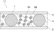
- FIG. 1 is a cross-sectional view schematically showing colored resin particles according to the first embodiment of the present invention.
- FIG. 2 is a cross-sectional view schematically showing a PDLC-type light control laminate containing colored resin particles according to the first embodiment of the present invention.
- FIG. 3 is a cross-sectional view schematically showing an SPD-type light control laminate containing colored resin particles according to the first embodiment of the present invention.
- (meth)acrylate means one or both of “acrylate” and “methacrylate”
- (meth)acryl means one or both of "acrylic” and “methacrylic”. means both.
- the colored resin particles according to the present invention contain resin particles and a colorant.
- the colored resin particles according to the present invention have a volume resistivity of 1.0 ⁇ 10 10 ⁇ cm or more.
- the colored resin particles according to the present invention have the above configuration, the gap between the base materials can be controlled with high accuracy.
- the colored resin particles according to the present invention are provided with the above configuration, even if the colored resin particles are broken and the coloring agent inside flows out when used as a spacer, a short circuit occurs. can be suppressed. As a result, it is possible to improve the conduction reliability of the obtained light control laminate.
- the colored resin particles according to the present invention can suppress light leakage.
- a spherical shape is not limited to a true spherical shape, but includes a substantially spherical shape, and includes, for example, a shape having an aspect ratio (major axis/minor axis) of 1.5 or less.
- the volume resistivity of the colored resin particles is preferably 1.0 ⁇ 10 11 ⁇ cm or more, more preferably 1.0 ⁇ 10 12 ⁇ cm or more, and still more preferably 1.0 ⁇ 10 13 ⁇ cm or more. is.
- the upper limit of the volume resistivity of the colored resin particles is not particularly limited.
- the volume resistivity of the colored resin particles may be 1.0 ⁇ 10 20 ⁇ cm or less, or 1.0 ⁇ 10 18 ⁇ cm or less.
- the volume resistivity of the colored resin particles can be measured as follows. Using a powder resistance measurement system (for example, "Powder resistance measurement system MCP-PD51 type” manufactured by Mitsubishi Chemical Analytech Co., Ltd.), the colored resin particles filled in the probe are measured from 0 kN to 20 kN in increments of 4 kN with a hydraulic pump. load with . The volume resistivity of the colored resin particles under each load (0 kN, 4 kN, 8 kN, 12 kN, 16 kN, and 20 kN) is measured, and the lowest value is taken as the volume resistivity of the colored resin particles.
- a powder resistance measurement system for example, "Powder resistance measurement system MCP-PD51 type” manufactured by Mitsubishi Chemical Analytech Co., Ltd.
- Examples of a method for easily controlling the volume resistivity of the colored resin particles within a suitable range include a method for adjusting the type and content of the coloring agent.
- the 20% K value of the colored resin particles is preferably 100 N/mm 2 or more, more preferably 700 N/mm 2 or more, still more preferably 1000 N/mm 2 or more, preferably 5000 N/mm 2 or less, more preferably It is 4000 N/mm 2 or less, more preferably 3000 N/mm 2 or less.
- the 20% K value of the colored resin particles is equal to or higher than the lower limit and equal to or lower than the upper limit, the gap between the substrates can be controlled with higher accuracy, and the substrate can be prevented from being damaged.
- the 20% K value of the colored resin particles is equal to or more than the lower limit and equal to or less than the upper limit, it is possible to suppress destruction of the colored resin particles, thereby suppressing outflow of the colorant in the colored resin particles. It is possible to suppress the occurrence of a short circuit. As a result, it is possible to improve the conduction reliability of the obtained light control laminate.
- the 20% K value of the colored resin particles can be measured as follows. Using a microcompression tester, the colored resin particles are compressed at 25° C. with a smooth indenter end surface of a cylinder (diameter 50 ⁇ m, made of diamond) under conditions of applying a maximum test load of 20 mN for 60 seconds. The load value (N) and compression displacement (mm) at this time are measured. The 20% K value can be obtained from the obtained measured values by the following formula. As the microcompression tester, for example, "Fischer Scope H-100" manufactured by Fisher Co., Ltd. is used.
- Methods for easily controlling the 20% K value of the colored resin particles within a suitable range include adjusting the number of polymerizable functional groups and the molecular weight of the material (polymerizable monomer) for forming the resin particles, Examples include a method of adjusting the crosslink density of the colored resin particles by adjusting the type and content of the coloring agent.
- the average particle size of the colored resin particles is preferably 1 ⁇ m or more, more preferably 3 ⁇ m or more, and still more preferably 10 ⁇ m or more. , preferably 150 ⁇ m or less, more preferably 100 ⁇ m or less, still more preferably 50 ⁇ m or less.
- the particle diameter of the colored resin particles means the diameter when the colored resin particles are spherical, and when the colored resin particles have a shape other than a spherical shape, it is assumed to be a true sphere corresponding to the volume. means the diameter when The particle size of the colored resin particles is preferably an average particle size, more preferably a number average particle size.
- the particle size of the colored resin particles can be measured by any particle size distribution analyzer. For example, it can be measured using a particle size distribution measuring apparatus using the principle of laser light scattering, electrical resistance value change, image analysis after imaging, or the like.
- a particle size distribution measuring device (“Multisizer 4" manufactured by Beckman Coulter) is used to measure the particle size of about 100,000 colored resin particles, and the average value is A method of calculating is exemplified.
- the colored resin particles do not contain particles (colored resin particles) having a particle diameter of 1.2 times or more the average particle diameter, or It is preferable to contain particles (colored resin particles) having a particle diameter of 1.2 times or more the average particle diameter at 1000 ppm or less.
- the content of particles (colored resin particles) having a particle diameter of 1.2 times or more the average particle diameter is preferably 1000 ppm or less. It is more preferably 500 ppm or less, still more preferably 100 ppm or less, and particularly preferably 50 ppm or less.
- the content of particles (colored resin particles) having a particle diameter 1.2 times or more the average particle diameter should be 0 ppm (not contained). is most preferred.
- the content of particles (colored resin particles) having a particle diameter 1.2 times or more the average particle diameter can be measured as follows.
- the colored resin particles are filtered through a filter having a pore size 1.15 times the average particle diameter, the colored resin particles remaining on the filter are observed with an optical microscope, and the colored resin particles 1.2 times or more the average particle diameter are counted. do.
- the content of particles (colored resin particles) having a particle diameter 1.2 times or more the average particle diameter is calculated.
- the CV value of the particle diameter of the colored resin particles is preferably 2.0% or more, more preferably 2.5% or more, and preferably It is 10% or less, more preferably 8.0% or less.
- the CV value (variation coefficient) of the particle diameter of the colored resin particles can be measured as follows.
- CV value (%) ( ⁇ /Dn) ⁇ 100 ⁇ : standard deviation of the particle size of the colored resin particles Dn: average value of the particle size of the colored resin particles
- the aspect ratio of the colored resin particles is preferably 1.5 or less, more preferably 1.3 or less, from the viewpoint of controlling the gap between the substrates with higher accuracy.
- the above aspect ratio indicates major axis/minor axis.
- the aspect ratio is obtained by observing 10 arbitrary colored resin particles with an electron microscope or an optical microscope, taking the maximum diameter and the minimum diameter as the major diameter and the minor diameter, respectively, and averaging the major diameter / minor diameter of each spherical colored resin particle. It is preferable to obtain by calculating the value.
- the lower limit of the aspect ratio of the colored resin particles is not particularly limited.
- the aspect ratio of the colored resin particles may be 1.0 or more, or 1.1 or more.
- the specific gravity of the colored resin particles is preferably 1.5 or less, more preferably 1.4 or less, and still more preferably 1.3. It is below.
- the lower limit of the specific gravity of the colored resin particles is not particularly limited.
- the specific gravity of the colored resin particles may be 1.0 or more, or 1.1 or more.
- JIS Z8781-4 was used for each of the colored resin particles before light irradiation and the colored resin particles after light irradiation with an integrated light amount of 540 MJ/m 2 .
- the color resin particles have a lightness L 0 * of 0 or more and 60 or less before light irradiation, when the lightness is measured in the L*a*b* color system according to :2013.
- the lightness L 0 * of the colored resin particles before light irradiation is preferably 0 or more, more preferably 1 or more, and still more preferably 3 or more. , preferably 60 or less, more preferably 40 or less, and still more preferably 30 or less.
- the lightness L 540 * of the colored resin particles after light irradiation is preferably 1 or more, more preferably 3 or more, and still more preferably 4 or more. , preferably 60 or less, more preferably 50 or less, and still more preferably 40 or less.
- the ratio of the lightness L 0 * of the colored resin particles before light irradiation to the lightness L 540 * of the colored resin particles after light irradiation is preferably 0.1 or more, more preferably 0.3 or more, still more preferably 0.4 or more, particularly preferably 0.6 or more, and most preferably 0.8 or more.
- the upper limit of the ratio (L 0 */L 540 *) is not particularly limited.
- the ratio (L 0 */L 540 *) may be 1.0 or less.
- the lightness L 0 * of the colored resin particles before light irradiation is 0 or more and 60 or less, and the colored resin before light irradiation It is particularly preferable that the ratio of the lightness L 0 * of the particles to the lightness L 540 * of the colored resin particles after light irradiation (L 0 */L 540 *) is 0.1 or more.
- the lightness L 0 * of the colored resin particles before light irradiation and the lightness L 540 * of the colored resin particles after light irradiation can be measured as follows.
- a plate-like sample having the same composition as the colored resin particles is prepared.
- the plate-shaped sample is irradiated with light at an illuminance of 255 W/m 2 for 588 hours (accumulated light quantity: 540 MJ/m 2 ).
- the sample before light irradiation and the sample after light irradiation were measured for arbitrary 10 points using a color difference meter, and the lightness was measured using a circular measurement range of 8 mm in diameter .
- Examples of the color difference meter include "TES-3250" manufactured by SATOTECH.
- the lightness L 0 * of the colored resin particles before light irradiation and the lightness L 540 * of the colored resin particles after light irradiation may be measured for each colored resin particle.
- the colored resin particles before and after light irradiation are carried on an adhesive tape, and the lightness is measured using a color difference meter for arbitrary 10 points of the colored resin particles, with the measurement range being a circle with a diameter of 8 mm. , the respective average values are defined as lightness L 0 * and lightness L 540 *.
- Examples of the color difference meter include "TES-3250" manufactured by SATOTECH.
- the colored resin particles after light irradiation are obtained by irradiating the colored resin particles with light at an illuminance of 255 W/m 2 for 588 hours (accumulated light quantity: 540 MJ/m 2 ).
- the visible light transmittance of the colored resin particles is preferably 40% or less, more preferably 20% or less, and even more preferably 10% or less.
- the visible light transmittance of the colored resin particles can be measured as follows. A plate-shaped sample having the same composition as that of the colored resin particles is prepared, spectrometry or the like is performed, and the visible light transmittance can be measured according to ISO13837:2008. It can also be measured by a method conforming to the JIS K6714 standard.
- the colored resin particles according to the present invention are preferably used as spacers.
- the colored resin particles according to the present invention are particularly suitable for use as a spacer in a light control laminate.
- the colored resin particles may be used as a spacer for a light control glass, or may be used as a spacer for a light control film.
- the colored resin particles are preferably used as a spacer for a light control glass or a spacer for a light control film.
- the colored resin particles contain resin particles.
- the colored resin particles and the resin particles contain a resin.
- the colored resin particles and the resin particles preferably contain a polymer.
- the above polymer is obtained by polymerizing the polymerizable components.
- the colored resin particles and the resin particles preferably contain a component derived from a polymer component.
- the colored resin particles and the resin particles preferably contain a polymer as a polymer component.
- resins for forming the resin particles include polyolefin resins such as polyethylene, polypropylene, polystyrene, polyvinyl chloride, polyvinylidene chloride, polyisobutylene, and polybutadiene; acrylic resins such as polymethyl methacrylate and polymethyl acrylate; , polyamide, phenol formaldehyde resin, melamine formaldehyde resin, benzoguanamine formaldehyde resin, urea formaldehyde resin, phenol resin, melamine resin, benzoguanamine resin, urea resin, epoxy resin, unsaturated polyester resin, saturated polyester resin, polyethylene terephthalate, polysulfone, polyphenylene oxide , polyacetal, polyimide, polyamideimide, polyetheretherketone, polyethersulfone, and divinylbenzene polymer.
- polyolefin resins such as polyethylene, polypropylene, polystyrene, polyvinyl chloride, polyviny
- the divinylbenzene polymer may be a divinylbenzene copolymer.
- examples of the divinylbenzene copolymer and the like include a divinylbenzene-styrene copolymer and a divinylbenzene-(meth)acrylate copolymer.
- the resin for forming the resin particles contains one or more polymerizable monomers (polymerization components) having an ethylenically unsaturated group. It is preferably a polymer obtained by polymerizing two or more kinds.
- the polymerizable monomer having an ethylenically unsaturated group includes a non-crosslinkable monomer and a crosslinkable monomer. and a monomer of
- non-crosslinkable monomers examples include vinyl compounds such as styrene monomers such as styrene, ⁇ -methylstyrene, and chlorostyrene; methyl vinyl ether, ethyl vinyl ether, propyl vinyl ether, 1,4-butanediol divinyl ether; , cyclohexanedimethanol divinyl ether, diethylene glycol divinyl ether and other vinyl ether compounds; vinyl acetate, vinyl butyrate, vinyl laurate, vinyl stearate and other acid vinyl ester compounds; vinyl chloride, vinyl fluoride and other halogen-containing monomers; meth) acrylic compounds, methyl (meth) acrylate, ethyl (meth) acrylate, propyl (meth) acrylate, butyl (meth) acrylate, 2-ethylhexyl (meth) acrylate, lauryl (meth) acrylate, cetyl (meth) acryl
- crosslinkable monomers examples include vinyl monomers such as divinylbenzene, 1,4-divinyloxybutane and divinylsulfone as vinyl compounds; ) acrylate, polytetramethylene glycol diacrylate, tetramethylolmethane tri(meth)acrylate, tetramethylolmethane di(meth)acrylate, trimethylolpropane tri(meth)acrylate, dipentaerythritol tetra(meth)acrylate, dipentaerythritol hexa (meth)acrylate, dipentaerythritol penta(meth)acrylate, glycerol tri(meth)acrylate, glycerol di(meth)acrylate, polyethylene glycol di(meth)acrylate, polypropylene glycol di(meth)acrylate, polytetramethylene glycol di( Polyfunctional (meth)acrylate compounds such as meth)acrylate and 1,4-butan
- Heavy bond-containing silane alkoxides such as decamethylcyclopentasiloxane
- Cyclic siloxanes such as decamethylcyclopentasiloxane
- Modified (reactive) silicone oils such as one-end modified silicone oil, both-end silicone oil, and side-chain silicone oil
- (meth)acrylic acid, maleic acid and carboxyl group-containing monomers such as maleic anhydride.
- the resin particles can be obtained by polymerizing the polymerizable monomer having the ethylenically unsaturated group.
- the above polymerization method is not particularly limited, and polymerization can be carried out by known methods such as radical polymerization, ionic polymerization, polycondensation (condensation polymerization, polycondensation), addition condensation, living polymerization, and living radical polymerization.
- the resin particles can be easily obtained by performing radical polymerization or the like using the polymerizable monomer having the ethylenically unsaturated group.
- a method of suspension polymerization in the presence of a radical polymerization initiator, a seed polymerization method and a dispersion polymerization method which are methods of polymerizing by swelling a monomer together with a radical polymerization initiator using non-crosslinked seed particles, and the like. can be obtained by
- the polymer component contains a polyfunctional (meth)acrylate compound. That is, from the viewpoint of controlling the gap between substrates with higher accuracy, it is preferable that the colored resin particles and the resin particles contain a component derived from a polyfunctional (meth)acrylate compound.
- the polyfunctional (meth)acrylate compound may be a bifunctional (meth)acrylate compound, a trifunctional (meth)acrylate compound, or a trifunctional or higher (meth)acrylate compound. , a tetrafunctional (meth)acrylate compound, or a tetrafunctional or higher (meth)acrylate compound. Only one kind of the polyfunctional (meth)acrylate compound may be used, or two or more kinds thereof may be used in combination.
- the colored resin particles and the resin particles contain a bifunctional (meth)acrylate compound or a trifunctional (meth)acrylate compound. is preferred.
- the polyfunctional (meth)acrylate compound is preferably polytetramethylene glycol di(meth)acrylate or dipentaerythritol tetra(meth)acrylate.
- the content of the component derived from the polyfunctional (meth)acrylate compound in 100% by weight of the colored resin particles is preferably 10% by weight or more, more preferably 50% by weight or more, still more preferably 55% by weight or more, and particularly preferably is 60% by weight or more, preferably 95% by weight or less, more preferably 90% by weight or less, and even more preferably 80% by weight or less.
- the gap between the substrates can be controlled with even higher accuracy.
- the colored resin particles contain 50% by weight or more of a component derived from a polyfunctional (meth)acrylate compound in 100% by weight of the colored resin particles. It is preferably included in quantity.
- the content of the component derived from the polyfunctional (meth)acrylate compound in 100% by weight of the resin particles is preferably 10% by weight or more, more preferably 50% by weight or more, still more preferably 60% by weight or more, and particularly preferably It is 65% by weight or more, preferably 95% by weight or less, more preferably 90% by weight or less, and even more preferably 80% by weight or less.
- the content of the component derived from the polyfunctional (meth)acrylate compound is equal to or more than the lower limit and equal to or less than the upper limit, the gap between the substrates can be controlled with even higher accuracy.
- the colored resin particles contain a colorant.
- the coloring agent may be arranged in the resin particles, or may be arranged on the surface of the resin particles. From the viewpoint of enhancing the conduction reliability of the obtained light control laminate, the colorant is preferably arranged in the resin particles. The colorant is preferably contained in the resin particles.
- coloring agent examples include inorganic particles, dyes and pigments. Only one kind of the coloring agent may be used, or two or more kinds thereof may be used in combination.
- the inorganic particles include carbon black particles, carbon nanotube particles, titanium black particles, graphene particles, iron oxide particles, zinc oxide particles, calcium carbonate particles, alumina particles, kaolin clay particles, calcium silicate particles, magnesium oxide particles, hydroxide
- examples thereof include magnesium particles, aluminum hydroxide particles, magnesium carbonate particles, talc particles, feldspar particles, mica particles, barite particles, barium carbonate particles, titanium oxide particles, silica particles and glass beads.
- the inorganic particles are preferably carbon black particles or titanium black particles.
- the average particle size of the inorganic particles is preferably 0.01 ⁇ m or more, more preferably 0.5 ⁇ m or more, preferably 100 ⁇ m or less, more preferably 50 ⁇ m or less, and even more preferably 10 ⁇ m or less.
- the above average particle size indicates a weight average particle size.
- the average particle size can be measured by a dynamic light scattering method using a light scattering measurement device with a laser as a light source. Examples of the light scattering measurement device include "DLS-6000AL" manufactured by Otsuka Electronics Co., Ltd., and the like.
- the dyes include pyrene dyes, aminoketone dyes, anthraquinone dyes, and azo dyes.
- Examples of the pyrene dye include Solvent Green 5 (CAS79869-59-3) and Solvent Green 7 (CAS6358-69-6).
- aminoketone dyes examples include Solvent Yellow 98 (CAS 12671-74-8), Solvent Yellow 85 (CAS 12271-01-1) and Solvent Red 179 (CAS 8910-94-5), and Solvent Red 135 (CAS 71902-17-5). be done.
- anthraquinone dye examples include Solvent Yellow 163 (CAS 13676091-0), Solvent Red 207 (CAS 15958-69-6), Disperse Red 92 (CAS 12236-11-2), Solvent Violet 13 (CAS 81-48-1), Disperse Violet 31 (CAS6408- 72-6), Solvent Blue 97 (CAS 61969-44-6), Solvent Blue 45 (CAS 37229-23-5), Solvent Blue 104 (CAS 116-75-6) and Disperse Blue 214 (CAS 104491-84-1).
- azo dyes examples include Solvent Yellow 30 (CAS3321-10-4), Solvent Red164 (CAS70956-30-8), and Disperse Blue146 (CAS88650-91-3).
- the coloring agent preferably contains a pigment.
- a pigment when the colored resin particles are used as spacers, even if the colored resin particles are damaged and the coloring agent inside flows out, it is possible to suppress the occurrence of a short circuit. As a result, it is possible to further improve the conduction reliability of the obtained light control laminate.
- the pigment may be an organic pigment or an inorganic pigment.
- the organic pigment may or may not have a metal atom.
- the pigment may be a red pigment, a blue pigment, a yellow pigment, or a black pigment. Only one type of the pigment may be used, or two or more types may be used in combination.
- the pigment is more preferably an organic pigment. Pigments are more preferred, and organic black pigments are even more preferred.
- organic black pigment examples include anthraquinone-based pigments, anthanthrone-based pigments, dianthraquinonyl-based pigments, anthrapyrimidine-based pigments, flavanthrone-based pigments, diketopyrrolopyrrole-based pigments, quinacridone-based pigments, and diketopyrrolopyrrole-based pigments.
- indigo/thioindigo pigments perinone pigments, perylene pigments, phthalocyanine pigments, halogenated phthalocyanine pigments, indoline pigments, isoindoline pigments, isoindolinone pigments, indanthrone pigments, dioxazine pigments
- examples include quinophthalone pigments, nickel azo pigments, metal complex pigments, azo pigments (insoluble azo pigments, soluble azo pigments, high molecular weight azo pigments and azomethine azo black pigments), and aniline black pigments.
- the colorant is an organic black pigment, titanium black particles, or It preferably contains carbon black particles, more preferably contains an organic black pigment, and further preferably contains an azo pigment or a perylene pigment.
- the coloring agent preferably contains an azo pigment, titanium black particles, or carbon black particles.
- the average particle size of the organic black pigment is preferably 1 nm or more, more preferably 10 nm or more, preferably 500 nm or less, more preferably 300 nm or less, and still more preferably 100 nm or less.
- the above average particle size indicates a weight average particle size.
- the average particle size can be measured by a dynamic light scattering method using a light scattering measurement device with a laser as a light source. Examples of the light scattering measurement device include "DLS-6000AL" manufactured by Otsuka Electronics Co., Ltd., and the like.
- the colored resin particles preferably contain 20% by weight or less of the coloring agent in 100% by weight of the colored resin particles.
- the content of the coloring agent in 100% by weight of the colored resin particles is preferably 0.5% by weight or more, more preferably 1.0% by weight or more, and still more preferably 3.0% by weight or more. It is 20% by weight or less, more preferably 15% by weight or less, and even more preferably 10% by weight or less.
- the content of the coloring agent is at least the lower limit, it is possible to more effectively suppress light leakage.
- the content of the coloring agent is equal to or less than the upper limit, the insulation reliability of the colored resin particles can be further improved, and as a result, the conduction reliability of the obtained light control laminate can be further improved.
- the content of the colorant means the total content of the plurality of colorants.
- the colored resin particles may contain other components, if necessary.
- the other components include polymerization initiators, pigment dispersants, resin particle dispersants, surfactants, and the like. Only one of the other components may be used, or two or more thereof may be used in combination.
- a light control laminate according to the present invention includes a first base material, a second base material, and a light control layer disposed between the first base material and the second base material. .
- the light control layer contains the colored resin particles.
- the light control laminate according to the present invention has the above configuration, it is possible to control the gap between the base materials with high precision and to improve the conduction reliability of the obtained light control laminate.
- the light control layered product may be a PDLC (Polymer Dispersed Liquid Crystal) type light control layered product or an SPD (Suspended Particle Device) type light control layered product.
- the light control layered product is preferably an SPD type or PDLC type light control layered product. From the viewpoint of exhibiting the effect of the present invention more effectively, it is more preferable that the light control layered body is a PDLC type light control layered body.
- the light control laminate may not be a liquid crystal display device.
- the light control laminate may or may not have a curved surface portion.
- the light modulating laminate preferably has a curved surface portion.
- the light modulating laminate may have a folded or curved shape.
- the light modulating laminate preferably has a folded or curved shape, and is preferably used in a folded or curved shape.
- the light modulating laminate may have a bent portion or a curved portion. It is preferable that the light modulating laminate, the first base material, and the second base material have flexibility so that they can have a folded shape or a curved shape.
- the curvature of the curved surface portion of the light control laminate is preferably 300R or more and 1800R or less.
- the adhesive particles according to the present invention can The conduction reliability can be sufficiently improved over the entire dimming laminate.
- the light control laminate is preferably used for vehicle window glass, partitions, or the like.
- Examples of the vehicle include vehicles, ships, aircraft, and the like.
- the light control laminate is preferably used for window glass of vehicles such as vehicles, ships, and aircraft, partitions, and the like.
- the light control laminate is preferably a window glass or a partition, and more preferably a window glass or a partition for vehicles such as vehicles, ships, and aircraft.
- the light control laminate may be a window glass of a vehicle such as a vehicle, a ship, an aircraft, or the like, or may be a partition.
- the vehicle is a transportation vehicle.
- the partition may be a member that is arranged between the seats of the vehicle and partitions the seats.
- FIG. 1 is a cross-sectional view schematically showing colored resin particles according to the first embodiment of the present invention.
- the colored resin particles 1 contain resin particles and a colorant.
- the colored resin particles 1 have a volume resistivity of 1.0 ⁇ 10 10 ⁇ cm or more.
- FIG. 2 is a cross-sectional view schematically showing a PDLC-type light control laminate containing colored resin particles according to the first embodiment of the present invention.
- FIG. 3 is a cross-sectional view schematically showing an SPD-type light control laminate containing colored resin particles according to the first embodiment of the present invention.
- the size, thickness, shape and amount of addition of the light modulating layer and the colored resin particles are appropriately changed from the actual size and shape for convenience of illustration.
- the light modulating layer 4 is sandwiched between the first base material 2 and the second base material 3 .
- the light control layer 4 is arranged between the first base material 2 and the second base material 3 .
- a sealant may be arranged around the light control layer 4 .
- the light control layer 4 includes colored resin particles 1, liquid crystal capsules 4A, and a binder 4B.
- the liquid crystal capsule 4A is a liquid crystal material.
- the liquid crystal capsules 4A are dispersed in the binder 4B.
- the liquid crystal capsule 4A is held in a capsule shape in the binder 4B.
- the liquid crystal material may be encapsulated and dispersed in the binder, or the liquid crystal material may be dispersed in the binder as a continuous phase.
- the colored resin particles 1 are in contact with the first base material 2 and the second base material 3 . Colored resin particles 1 control the gap between first substrate 2 and second substrate 3 .
- Electrodes are formed on the surface of the first base material 2 and on the surface of the second base material 3 (not shown). Examples of materials for the electrodes include indium tin oxide (ITO). The electrodes are preferably transparent electrodes.
- the orientation of the liquid crystal molecules in the liquid crystal capsule 4A is not uniform. It scatters in the binder 4B and becomes opaque.
- the liquid crystal molecules in the liquid crystal capsule 4A are aligned in a direction parallel to the electric field.
- the binder 4B and the liquid crystal material have the same refractive index, light can be transmitted therethrough, resulting in a transparent state.
- the light modulating layer 5 is sandwiched between the first substrate 2 and the second substrate 3 .
- the light control layer 5 is arranged between the first base material 2 and the second base material 3 .
- the light control layer 5 includes colored resin particles 1, droplets 5A of light control suspension, and a resin matrix 5B. Droplets 5A of light conditioning suspension are dispersed in a resin matrix 5B. The droplets 5A of the light control suspension are held in a droplet state in the resin matrix 5B.
- the droplets 5A of the light adjusting suspension contain the dispersion medium 5Aa and the light adjusting particles 5Ab.
- the light adjusting particles 5Ab are dispersed in the dispersion medium 5Aa.
- the colored resin particles 1 are in contact with the first base material 2 and the second base material 3 . Colored resin particles 1 control the gap between first substrate 2 and second substrate 3 .
- Electrodes are formed on the surface of the first base material 2 and on the surface of the second base material 3 (not shown). Examples of materials for the electrodes include indium tin oxide (ITO). The electrodes are preferably transparent electrodes.
- the incident light is caused by the Brownian motion of the light control particles 5Ab dispersed in the dispersion medium 5Aa forming the liquid droplets 5A of the light control suspension. is absorbed, scattered, or reflected by the light control particles 5Ab, and the incident light cannot pass through the light control layer 5.
- the light adjustment particles 5Ab are arranged in a direction parallel to the electric field. Therefore, the incident light can pass between the arranged light adjusting particles 5Ab and can be transmitted through the light adjusting layer 5.
- the light control layer preferably has light control properties. Dimmability is a property that the visible light transmittance changes depending on whether or not an electric field is applied, and the amount of incident light can be adjusted.
- the light control layer contains the colored resin particles.
- the light modulating layer preferably further includes a binder and a liquid crystal material dispersed in the binder.
- the liquid crystal material is not particularly limited, and may be any liquid crystal material as long as it has the property of changing its orientation when an electric field is applied.
- the liquid crystal material may be dispersed in the binder as a continuous phase, or may be dispersed in the binder in the form of liquid crystal drops or liquid crystal capsules.
- Examples of the liquid crystal material include nematic liquid crystal and cholesteric liquid crystal.
- Examples of materials for the nematic liquid crystal include cyanobiphenyl, phenyl ester, azoxybenzene, fluorine-containing biphenyl, carbonate, and Schiff base materials. Only one kind of the nematic liquid crystal material may be used, or two or more kinds thereof may be used in combination.
- Materials for the cholesteric liquid crystal include steroidal cholesterol derivatives, Schiff bases, azos, azoxys, benzoates, biphenyls, terphenyls, cyclohexylcarboxylates, phenylcyclohexanes, biphenylcyclohexanes, and pyrimidines.
- cholesteric liquid crystal material Only one kind of the cholesteric liquid crystal material may be used, or two or more kinds thereof may be used in combination.
- the binder holds the liquid crystal material and suppresses the flow of the liquid crystal material.
- the binder is not particularly limited as long as it does not dissolve in the liquid crystal material, has strength to withstand external force, and has high transparency to reflected light and incident light.
- the binder material include water-soluble polymer materials such as gelatin, polyvinyl alcohol, cellulose derivatives, polyacrylic acid-based polymers, ethyleneimine, polyethylene oxide, polyacrylamide, polystyrene sulfonate, polyamidine, isoprene-based sulfonic acid polymers, and materials capable of forming an aqueous emulsion such as fluorine resin, silicone resin, acrylic resin, urethane resin, and epoxy resin. Only one kind of the binder material may be used, or two or more kinds thereof may be used in combination.
- the binder is preferably crosslinked with a crosslinking agent.
- the cross-linking agent is not particularly limited as long as it forms cross-links between the binders and hardens the binder, makes it insoluble, or makes it insoluble.
- Examples of the cross-linking agent include acetaldehyde, glutaraldehyde, glyoxal, potassium alum hydrate of a polyvalent metal salt compound, adipic acid dihydrazide, melamine formalin oligomer, ethylene glycol diglycidyl ether, polyamide epichlorohydrin, and polycarbodiimide. mentioned. Only one kind of the crosslinking agent may be used, or two or more kinds thereof may be used in combination.
- the light control layer further comprises a resin matrix and a light control suspension dispersed in the resin matrix.
- the light control suspension contains a dispersion medium and light control particles dispersed in the dispersion medium.
- the light adjusting particles include carbon-based materials such as polyiodide and carbon black, metal materials such as copper, nickel, iron, cobalt, chromium, titanium, and aluminum, and inorganic compound materials such as silicon nitride, titanium nitride, and aluminum oxide. etc. Also, these materials may be particles coated with a polymer. Only one type of the light adjusting particles may be used, or two or more types may be used in combination.
- the dispersion medium disperses the light adjustment particles in a fluid state.
- the dispersion medium selectively adheres to the light control particles, coats the light control particles, and causes the light control particles to migrate to the phase-separated droplet phase upon phase separation from the resin matrix.
- It is preferably a material that is functional, non-electrically conductive, and incompatible with the resin matrix.
- the dispersion medium is preferably a liquid copolymer having a refractive index similar to that of the resin matrix when the light control laminate is formed.
- a (meth)acrylic ester oligomer having a fluoro group or a hydroxyl group is preferable, and a (meth)acrylic ester oligomer having a fluoro group and a hydroxyl group is more preferable.
- the fluoro or hydroxyl monomer units are oriented toward the light modulating particles and the remaining monomer units stabilize the droplets of the light modulating suspension in the resin matrix. Therefore, the light control particles are easily dispersed in the light control suspension, and the light control particles are easily guided into the phase-separated droplets during phase separation from the resin matrix.
- Examples of the (meth)acrylic acid ester oligomer having a fluoro group or a hydroxyl group include 2,2,2-trifluoroethyl methacrylate/butyl acrylate/2-hydroxyethyl acrylate copolymer, and 3,5,5 acrylic acid.
- the weight average molecular weight of the (meth)acrylate oligomer is preferably 1000 or more, more preferably 2000 or more, and preferably 20000 or less, more preferably 10000 or less.
- the light control layer can be produced using the resin material for forming the resin matrix and the light control suspension.
- the resin material is preferably a resin material that cures when irradiated with energy rays.
- the resin material that is cured by irradiation with energy rays includes a polymer composition containing a photopolymerization initiator and a polymer compound that is cured by energy rays such as ultraviolet rays, visible rays, and electron beams.
- Examples of the polymer composition include a polymer composition containing a polymerizable monomer having an ethylenically unsaturated group and a photopolymerization initiator.
- Examples of the polymerizable monomer having an ethylenically unsaturated group include non-crosslinkable monomers and crosslinkable monomers.
- non-crosslinking monomer examples include the non-crosslinking monomers described above.
- crosslinkable monomer examples include the above-described crosslinkable monomers.
- photopolymerization initiator examples include 2,2-dimethoxy-1,2-diphenylethan-1-one, 1-(4-(2-hydroxyethoxy)phenyl)-2-hydroxy-2-methyl-1-propane -1-one, bis(2,4,6-trimethylbenzoyl)phenylphosphine oxide, 2-hydroxy-2-methyl-1-phenylpropan-1-one, and (1-hydroxycyclohexyl)phenylketone. be done.
- the resin material may contain organic solvent-soluble resin, thermoplastic resin, poly(meth)acrylic acid, and the like.
- the resin material may contain various additives such as an anti-coloring agent, an antioxidant, and an adhesion imparting agent, and may contain a solvent.
- the first substrate is preferably a transparent substrate.
- the second base material is preferably a transparent base material.
- the transparent substrate is, for example, a substrate having optical transparency (light transmissive substrate). For example, light is transmitted from one side of the transparent substrate to the other side through the transparent substrate. For example, when viewing a substance on the other side through the transparent substrate from one side of the transparent substrate, the substance can be visually recognized. Transparency also includes translucence, for example.
- the transparent substrate may be colorless and transparent, or may be colored and transparent.
- the materials of the first base material and the second base material are not particularly limited.
- the material of the first base material and the material of the second base material may be the same or different.
- materials for the first base material and the second base material include glass and resin films.
- the glass includes soda lime glass, lead glass, borosilicate glass for general construction, and glasses of various compositions for other applications, as well as functional glasses such as heat reflecting glass, heat absorbing glass, and tempered glass.
- the resin film include polyester films such as polyethylene terephthalate, polyolefin films such as polypropylene, and resin films such as acrylic resin films.
- the first substrate and the second substrate are preferably resin substrates, more preferably resin films, because they are excellent in transparency, moldability, adhesiveness, processability, and the like. , more preferably a polyethylene terephthalate film.
- the first base material and the second base material preferably include a base body and a conductive film formed on the surface of the base body so that an electric field for dimming can be applied.
- Examples of the conductive film include indium tin oxide (ITO), SnO 2 and In 2 O 3 .
- the conductive film is preferably a transparent conductive film.
- the visible light transmittance of the first base material and the second base material is preferably 75% or more, more preferably 80% or more.
- the visible light transmittance of the first base material and the second base material can be measured in accordance with ISO13837:2008 by carrying out spectrometry or the like.
- colorant Carbon black (inorganic black pigment) Titanium black (inorganic black pigment) Azo pigment (organic black pigment)
- Example 1 Preparation of colored resin particles (Example 1) To 30 parts by weight of divinylbenzene and 70 parts by weight of polytetramethylene glycol diacrylate, 5 parts by weight of carbon black was added and stirred to obtain a monomer mixture. 2000 parts by weight of a 2.5% by weight aqueous solution prepared by dissolving polyvinyl alcohol having a molecular weight of about 2000 in pure water was put into a reactor. The obtained monomer mixed solution was put into this and stirred to adjust the particle size so that the droplets of the monomer had a predetermined particle size. Next, the mixture was heated at 90° C. for 9 hours to polymerize the monomer droplets to obtain particles. After the obtained particles were washed several times with hot water and acetone respectively, a classification operation was performed to recover the colored resin particles.
- Example 2 to 14 and Comparative Example 2 Colored resin particles were produced in the same manner as in Example 1, except that the materials and contents (% by weight) of the colorants and resin particles were changed as shown in Tables 1-4.
- Comparative example 1 Resin particles were produced in the same manner as in Example 1, except that the material and content (% by weight) of the resin particles were changed as shown in Table 4. In Comparative Example 1, no coloring agent was used.
- PDLC type dimming laminate A known PDLC layer except that 5% by weight of the obtained colored resin particles or the resin particles of Comparative Example 1 was dispersed was placed between two PET films on which transparent and conductive ITO was deposited. A light control film was produced. A PDLC type light control laminate was produced by sandwiching a light control film between two sheets of transparent glass.
- a TN type liquid crystal display element was produced by the following method.
- a SiO 2 film was vapor-deposited on one surface of the first and second transparent substrates (transparent glass plate, 150 mm ⁇ 150 mm) by the CVD method, and then an ITO film was formed on the entire surface of the SiO 2 film by sputtering. Thereafter, a polyimide alignment film (“SE-7210” manufactured by Nissan Chemical Industries, Ltd.) was placed by spin coating, and baked at 280° C. for 90 minutes to form a polyimide alignment film. Next, after performing a rubbing treatment, the resulting colored resin particles were applied to the orientation film side of the first transparent substrate using a dry sprayer (“DISPA- ⁇ R” manufactured by Nisshin Engineering Co., Ltd.) at 20 per 1 mm 2 .
- DISPA- ⁇ R dry sprayer
- the resulting TN-type liquid crystal display element was sandwiched between polarizing films arranged in crossed Nicols so as to be in a normally white display mode, and a digital microscope ("VHX-2000" manufactured by Keyence Corporation) was observed while applying a voltage of 7 V. was used to observe the state of light leakage of the colored resin particles.
- the image magnification was set to 200 times, and the ratio of the number of colored resin particles through which light escaped was calculated in arbitrary 5 fields of view.
- the resin particles of Comparative Example 1 were also calculated in the same manner.
- the light leakage suppression property was judged according to the following criteria.
- the conduction reliability of the light control laminate was determined according to the following criteria.
- Connection resistance is 1.0 ⁇ 10 10 ⁇ / ⁇ or more ⁇ : Connection resistance is 1.0 ⁇ 10 9 ⁇ / ⁇ or more and less than 1.0 ⁇ 10 10 ⁇ / ⁇ ⁇ 1: Connection resistance is , 1.0 ⁇ 10 8 ⁇ / ⁇ or more and less than 1.0 ⁇ 10 9 ⁇ / ⁇ ⁇ 2: Connection resistance is 1.0 ⁇ 10 7 ⁇ / ⁇ or more and less than 1.0 ⁇ 10 8 ⁇ / ⁇ ⁇ : Connection resistance is less than 1.0 ⁇ 10 7 ⁇ / ⁇ / ⁇
- Gap controllability For the obtained light control laminate, the maximum value and minimum value of the distance between the substrates (transparent glass) were measured. Gap controllability was judged according to the following criteria.
- composition and results of the colored resin particles are shown in Tables 1 to 4 below.
Landscapes
- Physics & Mathematics (AREA)
- Nonlinear Science (AREA)
- General Physics & Mathematics (AREA)
- Optics & Photonics (AREA)
- Mathematical Physics (AREA)
- Chemical & Material Sciences (AREA)
- Crystallography & Structural Chemistry (AREA)
- Compositions Of Macromolecular Compounds (AREA)
- Laminated Bodies (AREA)
- Processes Of Treating Macromolecular Substances (AREA)
Abstract
Description
本発明に係る着色樹脂粒子は、樹脂粒子と、着色剤とを含む。本発明に係る着色樹脂粒子では、体積抵抗率が、1.0×10¹⁰Ω・cm以上である。
F:着色樹脂粒子が20%圧縮変形したときの荷重値(N)
S:着色樹脂粒子が20%圧縮変形したときの圧縮変位(mm)
R:着色樹脂粒子の半径(mm)
ρ:上記着色樹脂粒子の粒子径の標準偏差
Dn:上記着色樹脂粒子の粒子径の平均値
上記着色樹脂粒子は、樹脂粒子を含む。上記着色樹脂粒子及び上記樹脂粒子は、樹脂を含む。上記着色樹脂粒子及び上記樹脂粒子は、重合体を含むことが好ましい。上記重合体は、重合成分を重合させることにより得られる。上記着色樹脂粒子及び上記樹脂粒子は、重合成分に由来する成分を含むことが好ましい。上記着色樹脂粒子及び上記樹脂粒子は、重合成分の重合体を含むことが好ましい。
上記着色樹脂粒子は、着色剤を含む。上記着色剤は、上記樹脂粒子中に配置されていてもよく、上記樹脂粒子の表面上に配置されていてもよい。得られる調光積層体の導通信頼性を高める観点からは、上記着色剤は、上記樹脂粒子中に配置されていることが好ましい。上記着色剤は、上記樹脂粒子中に含まれることが好ましい。
上記着色樹脂粒子は、必要に応じて、他の成分を含んでいてもよい。上記他の成分としては、重合開始剤、顔料分散剤、樹脂粒子分散剤、及び界面活性剤等が挙げられる。上記他の成分は、1種のみが用いられてもよく、2種以上が併用されてもよい。
本発明に係る調光積層体は、第1の基材と、第2の基材と、上記第1の基材と上記第2の基材との間に配置された調光層とを備える。本発明に係る調光積層体は、上記調光層が、上記着色樹脂粒子を含む。
上記調光層は、調光性を有していることが好ましい。調光性とは、電界の印加の有無により可視光透過率が変化し、入射光量を調整することができる性質である。上記調光層は、上記着色樹脂粒子を含む。
上記調光層は、バインダーと、上記バインダー中に分散している液晶材料とをさらに含むことが好ましい。
上記調光層は、樹脂マトリックスと、上記樹脂マトリックス中に分散している光調整懸濁液とをさらに含むことが好ましい。
上記第1の基材は、透明基材であることが好ましい。上記第2の基材は、透明基材であることが好ましい。上記透明基材は、例えば、光透過性を有する基材(光透過性基材)である。例えば、透明基材の一方側から、透明基材を介して他方側に光が透過する。例えば、透明基材の一方側から、透明基材を介して他方側にある物質を目視したときに、物質を視認可能である。透明には、例えば半透明も含まれる。透明基材は、無色透明であってもよく、有色透明であってもよい。
カーボンブラック(無機黒色顔料)
チタンブラック(無機黒色顔料)
アゾ系顔料(有機黒色顔料)
スチレン
ジビニルベンゼン(純度96重量%、日鉄ケミカル&マテリアル社製「DVB960」)
ポリテトラメチレングリコールジアクリレート(多官能(メタ)アクリレート化合物、共栄社化学社製「PTMGA250」)
ペンタエリスリトールテトラアクリレート(多官能(メタ)アクリレート化合物、新中村化学工業社製「A-TMMT」)
(実施例1)
ジビニルベンゼン30重量部とポリテトラメチレングリコールジアクリレート70重量部とに、カーボンブラック5重量部を加えて撹拌し、モノマー混合液を得た。分子量約2000のポリビニルアルコールを純水に溶解させた2.5重量%水溶液2000重量部を、反応釜に入れた。この中に、得られたモノマー混合液を入れ、撹拌することで、モノマーの液滴が所定の粒径になるように、粒径を調整した。次に、90℃で9時間加熱し、モノマー液滴の重合反応を行って、粒子を得た。得られた粒子を熱水及びアセトンのそれぞれにて数回洗浄した後、分級操作を行って着色樹脂粒子を回収した。
着色剤、及び樹脂粒子の材料及び含有量(重量%)を表1~4に示すように変更したこと以外は、実施例1と同様にして、着色樹脂粒子を作製した。
樹脂粒子の材料及び含有量(重量%)を表4に示すように変更したこと以外は実施例1と同様にして、樹脂粒子を作製した。比較例1では、着色剤を用いなかった。
SPD方式の調光積層体:
透明かつ導電性を有するITOが蒸着されたPETフィルム2枚の間に、得られた着色樹脂粒子又は比較例1の樹脂粒子を5重量%分散させたこと以外は公知のSPD層が配置された調光フィルムを作製した。2枚の透明ガラスに調光フィルムを挟みこむことで、SPD方式の調光積層体を作製した。
透明かつ導電性を有するITOが蒸着されたPETフィルム2枚の間に、得られた着色樹脂粒子又は比較例1の樹脂粒子を5重量%分散させたこと以外は公知のPDLC層が配置された調光フィルムを作製した。2枚の透明ガラスに調光フィルムを挟みこむことで、PDLC方式の調光積層体を作製した。
(1)平均粒子径
得られた着色樹脂粒子及び比較例1の樹脂粒子について、粒度分布測定装置(ベックマンコールター社製「Multisizer4」)を用いて、約100000個の粒径を測定し、平均粒子径及び標準偏差を測定した。また、上述した方法で、平均粒子径の1.2倍以上の粒子径を有する粒子(着色樹脂粒子又は樹脂粒子)の含有量(ppm)を測定した。
得られた着色樹脂粒子及び比較例1の樹脂粒子について、上述した方法で、粒子径のCV値を算出した。
得られた着色樹脂粒子及び比較例1の樹脂粒子について、島津製作所社製「アキュピックII 1345 シリーズ」を用いて、比重を測定した。
得られた着色樹脂粒子及び比較例1の樹脂粒子100mgを、スライドガラスに貼りつけた粘着性テープ(長さ75mm、横幅15mm)上に薄く広げ、エアブローを30秒間行い、着色樹脂粒子を担持したサンプルを作製した。該サンプルに、255W/m2の照度で588時間(積算光量:540MJ/m2)、光を照射した。光照射前の該サンプルと、光照射後の該サンプルの任意の10点について、色彩色差計(SATOTECH社製「TES-3250」)を用いて、測定範囲を直径8mmの円形として明度を測定し、各平均値を明度L0*、明度L540*とした。また、比(L0*/L540*)を求めた。
得られた着色樹脂粒子及び比較例1の樹脂粒子について、フィッシャー社製「フィッシャースコープH-100」を用いて、上述した方法で、20%K値を測定した。
得られた着色樹脂粒子をTN(ツイステッドネマチック)型液晶表示素子用スペーサとして用いて、以下の方法でTN型液晶表示素子を作製した。
○○:光抜けしている着色樹脂粒子の個数の割合が1%未満
○:光抜けしている着色樹脂粒子の個数の割合が1%以上、3%未満
△:光抜けしている着色樹脂粒子の個数の割合が3%以上、5%未満
×:光抜けしている着色樹脂粒子の個数の割合が5%以上
得られた調光積層体において、2kg/cm2で10分間加圧した後、デジタルマイクロスコープ(キーエンス社製「VHX-2000」)を用いて観察し、破壊されている着色樹脂粒子の個数の割合を計測した。着色樹脂粒子の破壊抑制性を、以下の基準で判定した。
○○:破壊されている着色樹脂粒子の個数の割合が0.01%未満
○:破壊されている着色樹脂粒子の個数の割合が0.01%以上、0.1%未満
△1:破壊されている着色樹脂粒子の個数の割合が0.1%以上、0.5%未満
△2:破壊されている着色樹脂粒子の個数の割合が0.5%以上、1.0%未満
×:破壊されている着色樹脂粒子の個数の割合が1.0%以上
得られた調光積層体において、4端子法により上下の電極間の接続抵抗を測定し、接続抵抗の平均値を算出した。なお、電圧=電流×抵抗の関係から、一定の電流を流した時の電圧を測定することにより接続抵抗を求めることができる。調光積層体の導通信頼性を、以下の基準で判定した。
○○:接続抵抗が、1.0×10¹⁰Ω/□以上
○:接続抵抗が、1.0×10⁹Ω/□以上、1.0×1010Ω/□未満
△1:接続抵抗が、1.0×10⁸Ω/□以上、1.0×109Ω/□未満
△2:接続抵抗が、1.0×10⁷Ω/□以上、1.0×108Ω/□未満
×:接続抵抗が、1.0×10⁷Ω/□未満
得られた調光積層体について、基材(透明ガラス)間の距離の最大値及び最小値を測定した。ギャップ制御性を、以下の基準で判定した。
○○:基材間の距離の最大値が、最小値の1.05倍未満
○:基材間の距離の最大値が、最小値の1.05倍以上、1.10倍未満
△1:基材間の距離の最大値が、最小値の1.10倍以上、1.15倍未満
△2:基材間の距離の最大値が、最小値の1.15倍以上、1.20倍未満
×:基材間の距離の最大値が、最小値の1.20倍以上


2…第1の基材
3…第2の基材
4,5…調光層
4A…液晶カプセル
4B…バインダー
5A…光調整懸濁液の液滴
5Aa…分散媒
5Ab…光調整粒子
5B…樹脂マトリックス
11…PDLC方式の調光積層体
21…SPD方式の調光積層体
Claims (14)
- 樹脂粒子と、着色剤とを含み、
体積抵抗率が、1.0×10¹⁰Ω・cm以上である、着色樹脂粒子。 - 20%K値が、100N/mm2以上5000N/mm2以下である、請求項1に記載の着色樹脂粒子。
- 光照射前の着色樹脂粒子と540MJ/m2の積算光量で光を照射した光照射後の着色樹脂粒子とのそれぞれについて、JIS Z8781-4:2013に準拠したL*a*b*表色系における明度を測定したときに、
光照射前の着色樹脂粒子の明度L0*が、0以上60以下であり、
光照射前の着色樹脂粒子の明度L0*の、光照射後の着色樹脂粒子の明度L540*に対する比が、0.1以上である、請求項1又は2に記載の着色樹脂粒子。 - 平均粒子径が、1μm以上150μm以下である、請求項1~3のいずれか1項に記載の着色樹脂粒子。
- 平均粒子径の1.2倍以上の粒子径を有する粒子を含まないか、又は、平均粒子径の1.2倍以上の粒子径を有する粒子を1000ppm以下で含む、請求項1~4のいずれか1項に記載の着色樹脂粒子。
- 粒子径のCV値が、10%以下である、請求項1~5のいずれか1項に記載の着色樹脂粒子。
- 前記着色剤が、有機黒色顔料、チタンブラック粒子、又はカーボンブラック粒子を含む、請求項1~6のいずれか1項に記載の着色樹脂粒子。
- 着色樹脂粒子が、該着色樹脂粒子100重量%中、前記着色剤を20重量%以下の含有量で含む、請求項1~7のいずれか1項に記載の着色樹脂粒子。
- 比重が1.5以下である、請求項1~8のいずれか1項に記載の着色樹脂粒子。
- 着色樹脂粒子が、多官能(メタ)アクリレート化合物に由来する成分を含む、請求項1~9のいずれか1項に記載の着色樹脂粒子。
- 着色樹脂粒子が、該着色樹脂粒子100重量%中、多官能(メタ)アクリレート化合物に由来する成分を50重量%以上の含有量で含む、請求項1~10のいずれか1項に記載の着色樹脂粒子。
- スペーサとして用いられる、請求項1~11のいずれか1項に記載の着色樹脂粒子。
- 調光積層体において、スペーサとして用いられる、請求項12に記載の着色樹脂粒子。
- 第1の基材と、第2の基材と、前記第1の基材と前記第2の基材との間に配置された調光層とを備え、
前記調光層が、請求項1~13のいずれか1項に記載の着色樹脂粒子を含む、調光積層体。
Priority Applications (4)
| Application Number | Priority Date | Filing Date | Title |
|---|---|---|---|
| KR1020247016031A KR20240112274A (ko) | 2021-11-26 | 2022-11-21 | 착색 수지 입자 및 조광 적층체 |
| EP22898530.5A EP4439163A1 (en) | 2021-11-26 | 2022-11-21 | Colored resin particles and dimming laminate |
| JP2022573496A JPWO2023095747A1 (ja) | 2021-11-26 | 2022-11-21 | |
| CN202280071178.8A CN118202300A (zh) | 2021-11-26 | 2022-11-21 | 着色树脂粒子和调光叠层体 |
Applications Claiming Priority (2)
| Application Number | Priority Date | Filing Date | Title |
|---|---|---|---|
| JP2021191843 | 2021-11-26 | ||
| JP2021-191843 | 2021-11-26 |
Publications (1)
| Publication Number | Publication Date |
|---|---|
| WO2023095747A1 true WO2023095747A1 (ja) | 2023-06-01 |
Family
ID=86539486
Family Applications (1)
| Application Number | Title | Priority Date | Filing Date |
|---|---|---|---|
| PCT/JP2022/043023 WO2023095747A1 (ja) | 2021-11-26 | 2022-11-21 | 着色樹脂粒子及び調光積層体 |
Country Status (6)
| Country | Link |
|---|---|
| EP (1) | EP4439163A1 (ja) |
| JP (1) | JPWO2023095747A1 (ja) |
| KR (1) | KR20240112274A (ja) |
| CN (1) | CN118202300A (ja) |
| TW (1) | TW202336105A (ja) |
| WO (1) | WO2023095747A1 (ja) |
Cited By (1)
| Publication number | Priority date | Publication date | Assignee | Title |
|---|---|---|---|---|
| CN116360169A (zh) * | 2023-06-02 | 2023-06-30 | 合肥精卓光电有限责任公司 | 一种近黑色调光器件及其制备方法 |
Citations (3)
| Publication number | Priority date | Publication date | Assignee | Title |
|---|---|---|---|---|
| JPH1010540A (ja) | 1996-06-21 | 1998-01-16 | Hayakawa Rubber Co Ltd | 微粒子、スペーサー、微粒子の製造方法及び電気光学パネル |
| JP2000319529A (ja) * | 1999-05-12 | 2000-11-21 | Hayakawa Rubber Co Ltd | 合成樹脂系微粒子、電気光学パネル用スペーサ、合わせガラス用スペーサ及び塗料用充填材 |
| JP2002038048A (ja) * | 2000-06-07 | 2002-02-06 | Dmc 2 Degussa Metals Catalysts Cerdec Ag | 希土類酸化マンガンを含む顔料、該顔料を含有するコーティング組成物又はエナメル組成物、コーティングされた製品、該顔料の製造法及び製品の着色法 |
-
2022
- 2022-11-21 KR KR1020247016031A patent/KR20240112274A/ko unknown
- 2022-11-21 WO PCT/JP2022/043023 patent/WO2023095747A1/ja active Application Filing
- 2022-11-21 CN CN202280071178.8A patent/CN118202300A/zh active Pending
- 2022-11-21 JP JP2022573496A patent/JPWO2023095747A1/ja active Pending
- 2022-11-21 EP EP22898530.5A patent/EP4439163A1/en active Pending
- 2022-11-25 TW TW111145195A patent/TW202336105A/zh unknown
Patent Citations (3)
| Publication number | Priority date | Publication date | Assignee | Title |
|---|---|---|---|---|
| JPH1010540A (ja) | 1996-06-21 | 1998-01-16 | Hayakawa Rubber Co Ltd | 微粒子、スペーサー、微粒子の製造方法及び電気光学パネル |
| JP2000319529A (ja) * | 1999-05-12 | 2000-11-21 | Hayakawa Rubber Co Ltd | 合成樹脂系微粒子、電気光学パネル用スペーサ、合わせガラス用スペーサ及び塗料用充填材 |
| JP2002038048A (ja) * | 2000-06-07 | 2002-02-06 | Dmc 2 Degussa Metals Catalysts Cerdec Ag | 希土類酸化マンガンを含む顔料、該顔料を含有するコーティング組成物又はエナメル組成物、コーティングされた製品、該顔料の製造法及び製品の着色法 |
Non-Patent Citations (1)
| Title |
|---|
| no. 1 5 9 5 8 - 6 9 - 6 |
Cited By (2)
| Publication number | Priority date | Publication date | Assignee | Title |
|---|---|---|---|---|
| CN116360169A (zh) * | 2023-06-02 | 2023-06-30 | 合肥精卓光电有限责任公司 | 一种近黑色调光器件及其制备方法 |
| CN116360169B (zh) * | 2023-06-02 | 2023-10-24 | 合肥精卓光电有限责任公司 | 一种近黑色调光器件及其制备方法 |
Also Published As
| Publication number | Publication date |
|---|---|
| CN118202300A (zh) | 2024-06-14 |
| KR20240112274A (ko) | 2024-07-18 |
| JPWO2023095747A1 (ja) | 2023-06-01 |
| TW202336105A (zh) | 2023-09-16 |
| EP4439163A1 (en) | 2024-10-02 |
Similar Documents
| Publication | Publication Date | Title |
|---|---|---|
| TWI832804B (zh) | 調光積層體及調光積層體用樹脂間隔件 | |
| US12072583B2 (en) | Dimming laminate and resin spacer for dimming laminate | |
| WO2023095747A1 (ja) | 着色樹脂粒子及び調光積層体 | |
| WO2023095748A1 (ja) | 着色樹脂粒子及び調光積層体 | |
| WO2022131319A1 (ja) | 接着性粒子、接着剤及び調光積層体 | |
| JP7198668B2 (ja) | 複合粒子、複合粒子粉体及び調光材 | |
| WO2024135711A1 (ja) | シリコーン粒子及び調光積層体 | |
| WO2023090457A1 (ja) | 接着性粒子及び積層体 | |
| WO2023090456A1 (ja) | 接着性粒子及び積層体 | |
| CN116583407A (zh) | 粘接性粒子、粘接剂和调光叠层体 |
Legal Events
| Date | Code | Title | Description |
|---|---|---|---|
| WWE | Wipo information: entry into national phase |
Ref document number: 2022573496 Country of ref document: JP |
|
| 121 | Ep: the epo has been informed by wipo that ep was designated in this application |
Ref document number: 22898530 Country of ref document: EP Kind code of ref document: A1 |
|
| WWE | Wipo information: entry into national phase |
Ref document number: 202280071178.8 Country of ref document: CN |
|
| WWE | Wipo information: entry into national phase |
Ref document number: 2022898530 Country of ref document: EP |
|
| NENP | Non-entry into the national phase |
Ref country code: DE |
|
| ENP | Entry into the national phase |
Ref document number: 2022898530 Country of ref document: EP Effective date: 20240626 |