WO2023095649A1 - ボールねじ機構、型締装置、および射出成形機 - Google Patents
ボールねじ機構、型締装置、および射出成形機 Download PDFInfo
- Publication number
- WO2023095649A1 WO2023095649A1 PCT/JP2022/042151 JP2022042151W WO2023095649A1 WO 2023095649 A1 WO2023095649 A1 WO 2023095649A1 JP 2022042151 W JP2022042151 W JP 2022042151W WO 2023095649 A1 WO2023095649 A1 WO 2023095649A1
- Authority
- WO
- WIPO (PCT)
- Prior art keywords
- ball screw
- lock nut
- contact end
- injection molding
- molding machine
- Prior art date
- Legal status (The legal status is an assumption and is not a legal conclusion. Google has not performed a legal analysis and makes no representation as to the accuracy of the status listed.)
- Ceased
Links
Images


Classifications
-
- B—PERFORMING OPERATIONS; TRANSPORTING
- B29—WORKING OF PLASTICS; WORKING OF SUBSTANCES IN A PLASTIC STATE IN GENERAL
- B29C—SHAPING OR JOINING OF PLASTICS; SHAPING OF MATERIAL IN A PLASTIC STATE, NOT OTHERWISE PROVIDED FOR; AFTER-TREATMENT OF THE SHAPED PRODUCTS, e.g. REPAIRING
- B29C45/00—Injection moulding, i.e. forcing the required volume of moulding material through a nozzle into a closed mould; Apparatus therefor
- B29C45/03—Injection moulding apparatus
-
- B—PERFORMING OPERATIONS; TRANSPORTING
- B29—WORKING OF PLASTICS; WORKING OF SUBSTANCES IN A PLASTIC STATE IN GENERAL
- B29C—SHAPING OR JOINING OF PLASTICS; SHAPING OF MATERIAL IN A PLASTIC STATE, NOT OTHERWISE PROVIDED FOR; AFTER-TREATMENT OF THE SHAPED PRODUCTS, e.g. REPAIRING
- B29C45/00—Injection moulding, i.e. forcing the required volume of moulding material through a nozzle into a closed mould; Apparatus therefor
- B29C45/17—Component parts, details or accessories; Auxiliary operations
-
- B—PERFORMING OPERATIONS; TRANSPORTING
- B29—WORKING OF PLASTICS; WORKING OF SUBSTANCES IN A PLASTIC STATE IN GENERAL
- B29C—SHAPING OR JOINING OF PLASTICS; SHAPING OF MATERIAL IN A PLASTIC STATE, NOT OTHERWISE PROVIDED FOR; AFTER-TREATMENT OF THE SHAPED PRODUCTS, e.g. REPAIRING
- B29C45/00—Injection moulding, i.e. forcing the required volume of moulding material through a nozzle into a closed mould; Apparatus therefor
- B29C45/17—Component parts, details or accessories; Auxiliary operations
- B29C45/64—Mould opening, closing or clamping devices
Definitions
- the present invention relates to a ball screw mechanism, a mold clamping device, and an injection molding machine provided in an industrial machine.
- Patent Literature 1 describes a mold clamping device provided in an injection molding machine or a press.
- This mold clamping device is composed of a fixed platen, a movable platen, four sets of ball screw mechanisms connecting the fixed platen and the movable platen, and four servo motors provided in each ball screw mechanism. ing.
- the four servomotors are driven, the four sets of ball screw mechanisms are driven to slide the movable platen relative to the fixed platen. That is, the mold is opened and closed.
- the ball screw mechanism consists of a ball screw and a ball nut that the ball screw is screwed on.
- a ball screw is rotatably provided with respect to a member of an industrial machine.
- the ball screw is connected to the stationary platen via a bearing mechanism.
- a bearing retainer is provided on the stationary platen side, and a male screw is formed on the ball screw and a lock nut is provided.
- the bearing mechanism is sandwiched between a bearing retainer on the stationary platen side and a lock nut on the ball screw side. In this manner, the ball screw is rotatably connected to the stationary platen.
- the ball screw receives a thrust load from the members of the industrial machinery.
- a thrust load also acts on the lock nut.
- the lock nut has a contact end surface that contacts the bearing mechanism, and this contact end surface and the internal thread receive the thrust load.
- a large lock nut must be selected so as to withstand this load.
- a large load acts on the lock nut during mold clamping. Therefore, a large lock nut must be provided.
- a large space is required in order to provide the ball screw in the stationary platen. In other words, if the lock nut becomes larger, the space occupied by the ball screw mechanism in the member of the industrial machine becomes larger, and the layout of the ball screw mechanism and the size and shape of the member are restricted.
- the present disclosure provides a ball screw mechanism, a mold clamping device, and an injection molding machine equipped with a lock nut that can withstand a large load without increasing the size.
- the present disclosure configures a ball screw mechanism for industrial machines as follows.
- the ball screw mechanism is composed of a ball screw, a ball nut, a lock nut provided on a male screw formed on a part of the ball screw, a bearing mechanism that rotatably supports the ball screw, and a bearing retainer. It is The bearing mechanism is sandwiched between the bearing retainer and the locknut. That is, the lock nut has a contact end face, which is in contact with the bearing mechanism.
- the lock nut is provided with a load concentration relief portion that relieves the load acting on each thread of the internal thread formed therein from being concentrated on the thread near the contact end face.
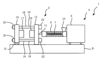
- FIG. 1 is a front view showing an injection molding machine according to this embodiment.
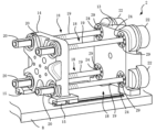
- FIG. 2 is a perspective view showing the mold clamping device according to this embodiment.
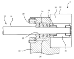
- FIG. 3 is a front cross-sectional view showing part of the mold clamping device according to this embodiment.
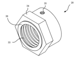
- FIG. 4 is a perspective view showing a lock nut provided in the ball screw mechanism according to this embodiment.
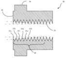
- FIG. 5 is a front cross-sectional view showing a lock nut provided in the ball screw mechanism according to this embodiment.
- FIG. 6 is a graph showing the load acting on each crest of the internal thread of the lock nut.
- FIG. 7 is a front cross-sectional view showing a lock nut according to the second embodiment.
- the ball screw mechanism according to this embodiment is A ball screw mechanism for industrial machinery, a ball screw; a ball nut screwed onto the ball screw; a lock nut provided on a male screw formed on a part of the ball screw; a bearing mechanism that rotatably supports the ball screw; a bearing retainer for sandwiching the bearing mechanism between the lock nut;
- the lock nut has a contact end surface in contact with the bearing mechanism, and has a load concentration relief portion that relieves the load acting on each crest of the internal thread from being concentrated on crests near the contact end surface.
- the industrial machine according to the present embodiment is an injection molding machine, and is preferably provided in a mold clamping device that constitutes the injection molding machine.
- the industrial machine according to the present embodiment is an injection molding machine, and is provided in a screw driving device that drives a screw of an injection device that constitutes the injection molding machine.
- the mold clamping device is first and second mold plates; and four sets of ball screw mechanisms that connect the first and second mold plates,
- the ball screw mechanism includes a ball screw, a ball nut screwed onto the ball screw; a lock nut provided on a male screw formed on a part of the ball screw; a bearing mechanism that rotatably supports the ball screw; a bearing retainer for sandwiching the bearing mechanism between the lock nut;
- the lock nut has a contact end surface in contact with the bearing mechanism, and has a load concentration relief portion that relieves the load acting on each crest of the internal thread from being concentrated on crests near the contact end surface.
- the injection molding machine is a mold clamping device for clamping the mold; and an injection device for injecting the injection material
- the mold clamping device includes first and second mold plates, and four sets of ball screw mechanisms that connect the first and second mold plates,
- the ball screw mechanism includes a ball screw, a ball nut screwed onto the ball screw; a lock nut provided on a male screw formed on a part of the ball screw; a bearing mechanism that rotatably supports the ball screw; a bearing retainer for sandwiching the bearing mechanism between the lock nut;
- the lock nut has a contact end surface in contact with the bearing mechanism, and has a load concentration relief portion that relieves the load acting on each crest of the internal thread from being concentrated on crests near the contact end surface.
- An injection molding machine 1 according to the present embodiment comprises a mold clamping device 2 provided on a bed B and an injection device 4, as shown in FIG.
- the injection device 4 comprises a heating cylinder 6 , a screw 7 inserted in the heating cylinder 6 , and a screw driving device 8 for driving the screw 7 .
- the heating cylinder 6 is provided with a hopper 10 and an injection nozzle 11 at its tip.
- the injection material is fed from the hopper 10 and the screw 7 is rotated to melt the injection material, which is weighed at the tip of the screw 7 .
- the screw 7 is driven in the axial direction, the injection material is injected.
- the mold clamping device 2 consists of a so-called two-platen mold clamping device. That is, the mold clamping device 2 includes first and second mold plates 13 and 14, that is, a fixed platen 13 and a movable platen 14, as shown in FIG.
- the stationary platen 13 is fixed on the bed B, and the movable platen 14 is placed on linear guides 15, 15 provided on the bed B.
- the movable platen 14 is slidable in directions toward and away from the fixed platen 13 .
- a fixed side mold 16 is attached to the stationary platen 13, and a movable side mold 17 is attached to the movable platen 14, respectively.
- the mold clamping device 2 is characterized in that the stationary platen 13 and the movable platen 14 are connected by four sets of ball screw mechanisms 18, 18, .
- Each of the ball screw mechanisms 18, 18, . . . includes ball screws 19, 19, .
- the movable platen 14 has through holes, and ball nuts 20, 20, . . . are fixed to the through holes. That is, the ball screws 19, 19, . . . are connected to the movable platen 14 via ball nuts 20, 20, . On the other hand, the ball screws 19, 19, .
- the fixed platen 13 is provided with servo motors 22, 22, . . . which are connected to ball screws 19, 19, . Therefore, when the servomotors 22, 22, . . . are driven, the ball screws 19, 19, . That is, the molds 16 and 17 (see FIG. 1) are opened and closed.
- the stationary platen 13 has a through hole 24, and the ball screw 19 is inserted into the through hole 24.
- the ball screw 19 is formed with a stepped portion 25 having a smaller outer diameter, and a bearing mechanism 26 is inserted in the stepped portion 25 .
- a male thread is formed in a part of the stepped portion 25, and a lock nut 28 according to the present embodiment described below is screwed onto this male thread.
- An annular bearing retainer 29 is fixed to the stationary platen 13 , and the bearing mechanism 26 is sandwiched between the bearing retainer 29 on the stationary platen 13 side and the lock nut 28 on the ball screw 19 side.
- the ball screw 19 is rotatably attached to the stationary platen 13 via the bearing mechanism 26 .
- the servomotor 22 consists of a stator 30 and a rotor 31 , and the rotor 31 is fixed to the end of the ball screw 19 .
- the lock nut 28 is similar in appearance to a conventional lock nut. That is, the lock nut 28 has a female thread 33 formed on its inner peripheral surface and a hexagonal nut portion 34 formed on its outer peripheral surface.
- the lock nut 28 is formed with a small-diameter screw hole 35 on its outer peripheral surface, but this screw hole 35 is for inserting a set screw or the like as appropriate for the purpose of preventing rotation, and is not essential. .
- the lock nut 28 is formed with a contact end surface 38 that contacts the bearing mechanism 26 (see FIG. 3).
- a strong thrust load acts between the contact end face 38 and the bearing mechanism 26 .
- a load acts on each crest of the internal thread 33 , but the load concentrates on crests near the contact end surface 38 . In other words, load bias occurs.
- the lock nut 28 according to the present embodiment is characterized in that it has a load concentration alleviating portion for alleviating load concentration on a portion of the ridges of the internal thread 33 and uneven load.
- the load concentration alleviating portion 39 in this embodiment is formed in a partial range of the internal thread 33 .
- FIG. 5 shows a front cross-sectional view of the lock nut 28 according to this embodiment, with the female thread 33 emphasized.
- the internal thread 33 is composed of a plurality of ridges when viewed in cross section. Among these ridges 37a, 37b, . . . , the ridges near the contact end face 38 are cut little by little at their apexes to form a tapered shape as a whole.
- the height of the crest is the lowest in the vicinity of the contact end surface 38 . That is, the first peak 37a closest to the contact end surface 38 has the lowest height. Next, the second peak 37b is slightly higher, and the third peak 37c, fourth peak 37d, .
- a thrust load acts on the lock nut 28 according to the present embodiment from the bearing mechanism 26 (see FIG. 3) and the ball screw 19 . At this time, among the ridges 37a, 37b, . As a result, even a relatively small lock nut 28 can withstand a sufficiently large load. I will explain this.
- Fig. 6 shows the share of the load acting on each thread of the female screw (thread load share (%)) for a conventional lock nut.
- the total load is distributed over each thread as shown in graph 40 . That is, 23% of the total load acts on the first crest, and 19%, 16%, 14%, 13%, and 16% of the total load acts on the second to sixth crests, respectively.
- the load sharing rate is the largest at the first peak, and decreases as the second and third peaks are reached.
- the share is slightly larger at the last mountain.
- the lock nut 28 (see FIG. 5) according to the present embodiment has a load concentration relief portion 39 . That is, the apexes of each of the ridges 37a, 37b, . . . Because of this configuration, the load acting on the first peak 37a is inevitably small. That is, the load sharing ratio is suppressed. Regarding the second peak 37b, the load sharing rate is suppressed, but the rate of suppression is reduced. The ratio of suppression of the load sharing ratio decreases as the third, fourth, and so on, the peaks 37c, . . . . . of the female thread of the lock nut 28 according to the present embodiment is as shown in the graph 45 of FIG.
- the lock nut 28 according to the present embodiment can withstand a large load. Therefore, the effect that the lock nut 28 can be miniaturized can be obtained.
- the load concentration alleviating portion among the threads of the female thread formed in the lock nut, at least a plurality of threads in the vicinity of the contact end face has a low top height. is preferably gradually lowered toward the contact end face.
- FIG. 7 shows a locknut 28' according to a second embodiment.
- each thread 37a', 37b', . . . That is, the heights of the tops of the respective ridges 37a', 37b', .
- this lock nut 28' has an outer peripheral surface 48 formed in a tapered shape. That is, the outer diameter of the lock nut 28' is formed to decrease as it approaches the one end surface 38'.
- the outer peripheral surface 48 tapered in this manner serves as a load concentration relief portion 39' that disperses the load of the female thread 33'.
- it is preferable that at least a part of the outer peripheral surface of the lock nut is tapered in the load concentration alleviating portion, and the outer diameter of the lock nut is reduced in the vicinity of the contact end surface.
- the load concentration relief portion 39 has been described as being formed in a partial range of the internal thread 33 .
- the entire range of the internal thread 33 can be used as the load concentration relief portion 39 .
- the ball screw mechanism 18 according to the present embodiment can also be applied to a conventional mold clamping device that has three mold plates and opens and closes molds with a toggle mechanism.
- the ball screw mechanism 18 according to the present embodiment can be applied to a ball screw mechanism that drives the crosshead of the toggle mechanism.
- the ball screw mechanism 18 according to this embodiment can also be applied to the screw driving device 8 of the injection device 4 .
- the ball screw mechanism 18 according to this embodiment can be applied not only to injection molding machines but also to other industrial machines such as press machines and machine tools.
Landscapes
- Engineering & Computer Science (AREA)
- Manufacturing & Machinery (AREA)
- Mechanical Engineering (AREA)
- Moulds For Moulding Plastics Or The Like (AREA)
- Injection Moulding Of Plastics Or The Like (AREA)
Abstract
ボールねじ機構(18)は、ボールねじ(19)と、ボールナット(20)と、ボールねじ(19)の一部に形成された雄ねじに設けられているロックナット(28)と、ボールねじ(19)を回転可能に支持する軸受機構(26)と、軸受押さえ(29)と、から構成されている。軸受機構(26)は軸受押さえ(29)とロックナット(28)との間に挟み込まれている。本開示は、ロックナット(28)に対して、その内部に形成されている雌ねじ(33)の各山(37a、37b、…)に作用する荷重の集中・偏りを緩和する荷重集中緩和部(39)を形成するようにする。
Description
本発明は、産業用機械に設けられているボールねじ機構、および型締装置、ならびに射出成形機に関するものである。
産業機械には、射出成形機、プレス機、工作機械等、色々な種類があり、これらにはモータの回転力を直線方向への駆動力に変換するボールねじ機構が設けられている。例えば、特許文献1には射出成形機もしくはプレス機に設けられる型締装置が記載されている。この型締装置は、固定盤と可動盤と、これら固定盤と可動盤とを連結する4組のボールねじ機構と、それぞれのボールねじ機構に設けられている4個のサーボモータとから構成されている。4個のサーボモータを駆動すると4組のボールねじ機構が駆動されて、可動盤が固定盤に対してスライドする。すなわち型開閉することになる。
ボールねじ機構は、ボールねじと、このボールねじが螺合しているボールナットとから構成されている。ボールねじは産業機械の部材に対して回転自在に設けられている。例えば、特許文献1の型締装置において示されているように、ボールねじは固定盤に対して軸受機構を介して接続されている。特許文献1には詳しく説明されていないが、固定盤側には軸受押さえが設けられ、ボールねじには雄ねじが形成されてロックナットが設けられている。軸受機構は、固定盤側の軸受押さえとボールねじ側のロックナットとによって挟み込まれている。このようにしてボールねじが固定盤に対して回転可能に接続されている。
ところで、ボールねじには産業機械の部材からスラスト荷重を受ける。スラスト荷重はロックナットにも作用する。ロックナットには軸受機構と接する接触端面が形成されており、この接触端面と、雌ねじとにおいて、このスラスト荷重を受けることになる。ロックナットはこの荷重に耐えるように、大型のものを選定しなければならないという問題がある。例えば特許文献1に記載の型締装置の場合には、型締め時においてロックナットに大きな荷重が作用する。したがって大型のロックナットを設けなければならない。しかしながらロックナットが大型化すると、固定盤においてボールねじを設けるために大きなスペースが必要になってしまう。つまり、ロックナットが大型化すれば、産業機械の部材におけるボールねじ機構が専有するスペースが大きくなり、ボールねじ機構の配置や部材の大きさ、形状等の設計において制約が生じてしまう。
以上のような問題を鑑み、本開示において、大型化することなく大きな荷重でも十分に耐えることができるロックナットを備えたボールねじ機構、型締装置および射出成形機を提供する。
その他の課題と新規な特徴は、本明細書の記述及び添付図面から明らかになるであろう。
本発明者らは、以下のような構成とすることにより上記課題を解決できることを見出した。
本開示は、産業機械用のボールねじ機構を次のように構成する。ボールねじ機構は、ボールねじと、ボールナットと、ボールねじの一部に形成された雄ねじに設けられているロックナットと、ボールねじを回転可能に支持する軸受機構と、軸受押さえと、から構成されている。軸受機構は軸受押さえとロックナットとの間に挟み込まれている。つまりロックナットは接触端面を備え、この接触端面が軸受機構と接している。本開示は、ロックナットに対して、その内部に形成されている雌ねじの各山に作用する荷重が、接触端面近傍の山に集中するのを緩和する荷重集中緩和部を設けるようにする。
本開示は、産業機械用のボールねじ機構を次のように構成する。ボールねじ機構は、ボールねじと、ボールナットと、ボールねじの一部に形成された雄ねじに設けられているロックナットと、ボールねじを回転可能に支持する軸受機構と、軸受押さえと、から構成されている。軸受機構は軸受押さえとロックナットとの間に挟み込まれている。つまりロックナットは接触端面を備え、この接触端面が軸受機構と接している。本開示は、ロックナットに対して、その内部に形成されている雌ねじの各山に作用する荷重が、接触端面近傍の山に集中するのを緩和する荷重集中緩和部を設けるようにする。
大型化することなく大きな荷重でも十分に耐えることができるロックナットを備えたボールねじ機構、型締装置および射出成形機を提供することができる。
以下、具体的な実施の形態について、図面を参照しながら詳細に説明する。ただし、以下の実施の形態に限定される訳ではない。説明を明確にするため、以下の記載及び図面は、適宜簡略化されている。各図面において、同一の要素には同一の符号が付されており、必要に応じて重複説明は省略されている。また、図面が煩雑にならないように、ハッチングが省略されている部分がある。
本実施の形態を説明する。
本実施の形態に係るボールねじ機構は、
産業機械用のボールねじ機構であって、
ボールねじと、
該ボールねじに螺合しているボールナットと、
前記ボールねじの一部に形成された雄ねじに設けられているロックナットと、
前記ボールねじを回転可能に支持する軸受機構と、
前記ロックナットとの間で前記軸受機構を挟み込むための軸受押さえと、を備え、
前記ロックナットは、前記軸受機構と接する接触端面を備え、内部に形成されている雌ねじの各山に作用する荷重が、前記接触端面近傍の山に集中するのを緩和する荷重集中緩和部を有する。
本実施の形態に係る産業機械は射出成形機であり、前記射出成形機を構成している型締装置に設けられていることが好ましい。
また、本実施の形態に係る産業機械は射出成形機であり、前記射出成形機を構成している射出装置のスクリュを駆動するスクリュ駆動装置に設けられていることが好ましい。
本実施の形態に係るボールねじ機構は、
産業機械用のボールねじ機構であって、
ボールねじと、
該ボールねじに螺合しているボールナットと、
前記ボールねじの一部に形成された雄ねじに設けられているロックナットと、
前記ボールねじを回転可能に支持する軸受機構と、
前記ロックナットとの間で前記軸受機構を挟み込むための軸受押さえと、を備え、
前記ロックナットは、前記軸受機構と接する接触端面を備え、内部に形成されている雌ねじの各山に作用する荷重が、前記接触端面近傍の山に集中するのを緩和する荷重集中緩和部を有する。
本実施の形態に係る産業機械は射出成形機であり、前記射出成形機を構成している型締装置に設けられていることが好ましい。
また、本実施の形態に係る産業機械は射出成形機であり、前記射出成形機を構成している射出装置のスクリュを駆動するスクリュ駆動装置に設けられていることが好ましい。
また、本実施の形態に係る型締装置は、
第1、2の型盤と、
前記第1、2の型盤を連結する4組のボールねじ機構と、を備え、
前記ボールねじ機構は、ボールねじと、
該ボールねじに螺合しているボールナットと、
前記ボールねじの一部に形成された雄ねじに設けられているロックナットと、
前記ボールねじを回転可能に支持する軸受機構と、
前記ロックナットとの間で前記軸受機構を挟み込むための軸受押さえと、を備え、
前記ロックナットは、前記軸受機構と接する接触端面を備え、内部に形成されている雌ねじの各山に作用する荷重が、前記接触端面近傍の山に集中するのを緩和する荷重集中緩和部を有する。
第1、2の型盤と、
前記第1、2の型盤を連結する4組のボールねじ機構と、を備え、
前記ボールねじ機構は、ボールねじと、
該ボールねじに螺合しているボールナットと、
前記ボールねじの一部に形成された雄ねじに設けられているロックナットと、
前記ボールねじを回転可能に支持する軸受機構と、
前記ロックナットとの間で前記軸受機構を挟み込むための軸受押さえと、を備え、
前記ロックナットは、前記軸受機構と接する接触端面を備え、内部に形成されている雌ねじの各山に作用する荷重が、前記接触端面近傍の山に集中するのを緩和する荷重集中緩和部を有する。
また、本実施の形態に係る射出成形機は、
金型を型締めする型締装置と、
射出材料を射出する射出装置とからなり、
前記型締装置は、第1、2の型盤と、
前記第1、2の型盤を連結する4組のボールねじ機構と、を備え、
前記ボールねじ機構は、ボールねじと、
該ボールねじに螺合しているボールナットと、
前記ボールねじの一部に形成された雄ねじに設けられているロックナットと、
前記ボールねじを回転可能に支持する軸受機構と、
前記ロックナットとの間で前記軸受機構を挟み込むための軸受押さえと、を備え、
前記ロックナットは、前記軸受機構と接する接触端面を備え、内部に形成されている雌ねじの各山に作用する荷重が、前記接触端面近傍の山に集中するのを緩和する荷重集中緩和部を有する。
金型を型締めする型締装置と、
射出材料を射出する射出装置とからなり、
前記型締装置は、第1、2の型盤と、
前記第1、2の型盤を連結する4組のボールねじ機構と、を備え、
前記ボールねじ機構は、ボールねじと、
該ボールねじに螺合しているボールナットと、
前記ボールねじの一部に形成された雄ねじに設けられているロックナットと、
前記ボールねじを回転可能に支持する軸受機構と、
前記ロックナットとの間で前記軸受機構を挟み込むための軸受押さえと、を備え、
前記ロックナットは、前記軸受機構と接する接触端面を備え、内部に形成されている雌ねじの各山に作用する荷重が、前記接触端面近傍の山に集中するのを緩和する荷重集中緩和部を有する。
<本実施の形態に係る射出成形機>
本実施の形態に係る射出成形機1は、図1に示されているように、ベッドBに設けられている型締装置2と、射出装置4とから構成されている。
本実施の形態に係る射出成形機1は、図1に示されているように、ベッドBに設けられている型締装置2と、射出装置4とから構成されている。
<射出装置>
最初に射出装置4を説明する。射出装置4は加熱シリンダ6と、この加熱シリンダ6に入れられているスクリュ7と、スクリュ7を駆動するスクリュ駆動装置8とから構成されている。加熱シリンダ6にはホッパ10が設けられ、そして先端に射出ノズル11が設けられている。ホッパ10から射出材料が投入され、そしてスクリュ7を回転して射出材料を溶融するとスクリュ7の先端に計量される。スクリュ7を軸方向に駆動すると射出材料が射出されるようになっている。
最初に射出装置4を説明する。射出装置4は加熱シリンダ6と、この加熱シリンダ6に入れられているスクリュ7と、スクリュ7を駆動するスクリュ駆動装置8とから構成されている。加熱シリンダ6にはホッパ10が設けられ、そして先端に射出ノズル11が設けられている。ホッパ10から射出材料が投入され、そしてスクリュ7を回転して射出材料を溶融するとスクリュ7の先端に計量される。スクリュ7を軸方向に駆動すると射出材料が射出されるようになっている。
<型締装置>
本実施の形態に係る型締装置2は、いわゆる2プラテンの型締装置からなる。すなわち型締装置2は、図2に示されているように、第1、2の型盤13、14、つまり固定盤13と可動盤14とを備えている。固定盤13はベッドB上に固定されており、可動盤14はベッドB上に設けられたリニアガイド15、15に載せられている。すなわち可動盤14は固定盤13に接近・離間する方向にスライド自在になっている。固定盤13には固定側金型16が、そして可動盤14には可動側金型17がそれぞれ取り付けられている。
本実施の形態に係る型締装置2は、いわゆる2プラテンの型締装置からなる。すなわち型締装置2は、図2に示されているように、第1、2の型盤13、14、つまり固定盤13と可動盤14とを備えている。固定盤13はベッドB上に固定されており、可動盤14はベッドB上に設けられたリニアガイド15、15に載せられている。すなわち可動盤14は固定盤13に接近・離間する方向にスライド自在になっている。固定盤13には固定側金型16が、そして可動盤14には可動側金型17がそれぞれ取り付けられている。
本実施の形態に係る型締装置2は、固定盤13と可動盤14とが4組のボールねじ機構18、18、…によって連結されている点に特徴がある。それぞれのボールねじ機構18、18、…は、ボールねじ19、19、…と、ボールねじ19、19、…が螺合するボールナット20、20、…とを備えている。
図2には示されていないが、可動盤14には貫通孔が開けられており、この貫通孔にボールナット20、20、…が固着されている。つまりボールねじ19、19、…はボールナット20、20、…を介して可動盤14に接続されている。一方、ボールねじ19、19、…は、次に詳しく説明するように固定盤13を貫通し、固定盤13に対して回転可能に支持されている。固定盤13にはサーボモータ22、22、…が設けられ、ボールねじ19、19、…と接続されている。したがって、サーボモータ22、22、…を駆動するとボールねじ19、19、…が回転し、可動盤14がスライドすることになる。すなわち金型16、17(図1参照)が型開閉される。
ボールねじ19、19、…と、固定盤13との接続について説明する。図3に示されているように、固定盤13には貫通孔24が開けられており、ボールねじ19はこの貫通孔24に入れられている。ボールねじ19には、外径が小さくなっている段部25が形成されており、この段部25に軸受機構26が入れられている。段部25には、一部の範囲に雄ねじが形成されており、次に説明する本実施の形態に係るロックナット28がこの雄ねじに螺合している。固定盤13には環状の軸受押さえ29が固定されており、軸受機構26は固定盤13側の軸受押さえ29と、ボールねじ19側のロックナット28とによって挟み込まれている。このようにしてボールねじ19は、軸受機構26を介して固定盤13に回転可能に取り付けられている。サーボモータ22はステータ30とロータ31とからなり、ボールねじ19の端部にロータ31が固定されている。
<ロックナット>
本実施の形態に係るロックナット28は、図4に示されているように、その外観は従来のロックナットに類似している。つまりロックナット28は、内周面に雌ねじ33が形成されており、その外周面には六角ナット部34が形成されている。なお、このロックナット28には、その外周面に小径のネジ穴35が形成されているが、このネジ穴35は回り止めを目的として適宜イモネジ等を挿入するためのものであり、必須ではない。
本実施の形態に係るロックナット28は、図4に示されているように、その外観は従来のロックナットに類似している。つまりロックナット28は、内周面に雌ねじ33が形成されており、その外周面には六角ナット部34が形成されている。なお、このロックナット28には、その外周面に小径のネジ穴35が形成されているが、このネジ穴35は回り止めを目的として適宜イモネジ等を挿入するためのものであり、必須ではない。
ロックナット28には、軸受機構26(図3参照)と接触する接触端面38が形成されている。この接触端面38において軸受機構26との間に強いスラスト荷重が作用することになる。雌ねじ33の各山にはそれぞれ荷重が作用するが、接触端面38の近傍の山において荷重が集中する。つまり荷重の偏りが発生する。
本実施の形態に係るロックナット28は、雌ねじ33の一部の山に荷重が集中し、荷重が偏ることを緩和するための、荷重集中緩和部を備えている点に特徴がある。本実施の形態における荷重集中緩和部39は、雌ねじ33の一部の範囲に形成されている。図5には、本実施の形態に係るロックナット28の正面断面図が示され、雌ねじ33が強調して示されている。雌ねじ33は断面図で見ると複数の山から構成されている。これらの各山37a、37b、…のうち、接触端面38近傍の山について頂部が少しずつカットされ、全体としてテーパ状になっている。これによって山の高さは接触端面38近傍で一番低い。つまり接触端面38に一番近い1個目の山37aにおいてその高さが最も低い。次いで、2個目の山37bにおいてわずかに高くなり、3個目の山37c、4個目の山37d、…と内部に向かうに従って、その高さが高くなっている。
<ロックナットの作用>
本実施の形態に係るロックナット28は、軸受機構26(図3参照)とボールねじ19とからスラスト荷重が作用する。このとき、雌ねじ33(図5参照)を構成している各山37a、37b、…のうち、接触端面38近傍の山に集中的に作用する荷重が緩和されるようになっている。これによって比較的小型のロックナット28であっても、十分に大きな荷重に耐えることができるようになっている。これを説明する。
本実施の形態に係るロックナット28は、軸受機構26(図3参照)とボールねじ19とからスラスト荷重が作用する。このとき、雌ねじ33(図5参照)を構成している各山37a、37b、…のうち、接触端面38近傍の山に集中的に作用する荷重が緩和されるようになっている。これによって比較的小型のロックナット28であっても、十分に大きな荷重に耐えることができるようになっている。これを説明する。
図6には、従来のロックナットについて、雌ねじの各山に作用する荷重の分担率(ねじ山荷重分担率(%))が示されている。例えば、雌ねじの山数が6個のロックナットについて、グラフ40で示されているように、全体荷重が各山に分散している。つまり1個目の山において全体荷重の23%が、2個目~6個目の山においてそれぞれ19%、16%、14%、13%、16%が作用している。つまり、荷重の分担率は1個目の山で最も大きく、2個目、3個目になるに従って低下する。ただし、最後の山において分担率は若干大きくなっている。同様に、グラフ41、42、43で示されているように、雌ねじの山数が8個、10個、12個のそれぞれのロックナットについても、最初の1個目の山で荷重の分担率が最も大きく、2個目、3個目になるに従って分担率が低下し、最後の山で若干大きくなっている。このようになっているので従来のロックナットは接触端面の近傍の1個目の山に集中的に大きな荷重が作用する。
これに対して本実施の形態に係るロックナット28(図5参照)は、荷重集中緩和部39を備えている。つまり雌ねじ33の各山37a、37b、…についてその頂部がカットされ、全体としてテーパ状になっている。このようになっているので、1個目の山37aに作用する荷重は、必然的に小さくなる。つまり荷重分担率は抑制される。2個目の山37bについては荷重分担率が抑制されるが抑制の割合は低下する。3個目、4個目の山37c、…にいくに従って荷重分担率の抑制の割合は低下することになる。このようになるので、本実施の形態に係るロックナット28の雌ねじの各山37a、37b、…における荷重分担率は、図6のグラフ45のようになる。このように荷重分担率が平均化することによって本実施の形態に係るロックナット28は大きな荷重に耐えることができる。従って、ロックナット28を小型化することができる、という効果が得られる。
本実施の形態において、荷重集中緩和部では、ロックナットに形成されている雌ねじの各山のうち、少なくとも前記接触端面近傍の複数の山について頂部の高さが低くなっており、頂部の高さは前記接触端面に近づくにつれて徐々に低くなることが好ましい。
本実施の形態において、荷重集中緩和部では、ロックナットに形成されている雌ねじの各山のうち、少なくとも前記接触端面近傍の複数の山について頂部の高さが低くなっており、頂部の高さは前記接触端面に近づくにつれて徐々に低くなることが好ましい。
<第2の実施の形態に係るロックナット>
本実施の形態は色々な変形が可能である。例えばロックナット28について変形することができ、図7には、第2の実施の形態に係るロックナット28’が示されている。このロックナット28’は、雌ねじ33’についての各山37a’、37b’、…は格別に加工が施されていない。すなわち各山37a’、37b’、…の頂部の高さは一定になっており、この点において従来のロックナットの雌ねじと同様になっている。しかしながら、このロックナット28’は、その外周面48がテーパ状に形成されている。つまり一方の端面38’に近づくにつれてロックナット28’の外径が小さくなるように、形成されている。このようにテーパ状に形成されている外周面48が、雌ねじ33’の荷重を分散する荷重集中緩和部39’になっている。
本実施の形態において、記荷重集中緩和部では、ロックナットの外周面の少なくとも一部がテーパ状で、ロックナットの外径が接触端面近傍で小さくなっていることが好ましい。
本実施の形態は色々な変形が可能である。例えばロックナット28について変形することができ、図7には、第2の実施の形態に係るロックナット28’が示されている。このロックナット28’は、雌ねじ33’についての各山37a’、37b’、…は格別に加工が施されていない。すなわち各山37a’、37b’、…の頂部の高さは一定になっており、この点において従来のロックナットの雌ねじと同様になっている。しかしながら、このロックナット28’は、その外周面48がテーパ状に形成されている。つまり一方の端面38’に近づくにつれてロックナット28’の外径が小さくなるように、形成されている。このようにテーパ状に形成されている外周面48が、雌ねじ33’の荷重を分散する荷重集中緩和部39’になっている。
本実施の形態において、記荷重集中緩和部では、ロックナットの外周面の少なくとも一部がテーパ状で、ロックナットの外径が接触端面近傍で小さくなっていることが好ましい。
第1の実施の形態に係るロックナット28(図5参照)に関して説明したように、ボールねじ19(図3参照)にスラスト荷重が作用すると、雌ねじ33のうち、接触端面38’に近い山37a’において最大の荷重が作用する。そして次の山37b’、その次の山37c’、…になるに従って順次荷重が低下する。この第2の実施の形態に係るロックナット28’においても同様になるが、荷重集中緩和部39’では外周面48がテーパ状になっていることにより各山37a’、37b’、37c’、…の荷重の集中が緩和される。なぜならば、より荷重が作用する37a’において外径が小さくなっているので、肉厚が薄くわずかに弾性変形しやすいからである。山37a’、次の山37b’、その次の山37c’、…になるに従って、肉厚が少しずつ厚くなり、それぞれ許容される弾性変形がわずかになっていく。このように弾性変形の許容度を変化させることによって、各山37a’、37b’、37c’、…の荷重の集中が緩和される。
<他の変形例>
第1の実施の形態に係るロックナット28(図5参照)において、荷重集中緩和部39は雌ねじ33の一部の範囲に形成されているように説明した。しかしながら、雌ねじ33の全ての範囲の山37a、37b、…についてそれらの頂部をカットして全体としてテーパ状にしてもよい。つまり雌ねじ33の全範囲を荷重集中緩和部39とすることもできる。
第1の実施の形態に係るロックナット28(図5参照)において、荷重集中緩和部39は雌ねじ33の一部の範囲に形成されているように説明した。しかしながら、雌ねじ33の全ての範囲の山37a、37b、…についてそれらの頂部をカットして全体としてテーパ状にしてもよい。つまり雌ねじ33の全範囲を荷重集中緩和部39とすることもできる。
本実施の形態に係るボールねじ機構18は、3個の型盤を備えトグル機構によって型開閉される従来の型締装置に対しても、適用することができる。トグル機構のクロスヘッドを駆動するボールねじ機構に本実施の形態に係るボールねじ機構18を適用することができる。さらには、射出装置4のスクリュ駆動装置8に本実施の形態に係るボールねじ機構18を適用することもできる。射出成形機だけでなく、他の産業機械、例えばプレス機、工作機械等に対しても本実施の形態に係るボールねじ機構18を適用することができる。
以上、本発明者によってなされた発明を実施の形態に基づき具体的に説明したが、本発明は既に述べた実施の形態に限定されるものではなく、その要旨を逸脱しない範囲において種々の変更が可能であることはいうまでもない。以上で説明した複数の例は、適宜組み合わせて実施されることもできる。
本開示によれば、大型化することなく大きな荷重でも十分に耐えることができるロックナットを備えたボールねじ機構、型締装置および射出成形機を提供することができる。
本発明を詳細にまた特定の実施態様を参照して説明したが、本発明の精神と範囲を逸脱することなく様々な変更や修正を加えることができることは当業者にとって明らかである。
本出願は、2021年11月25日出願の日本特許出願(特願2021-190687)に基づくものであり、その内容はここに参照として取り込まれる。
本出願は、2021年11月25日出願の日本特許出願(特願2021-190687)に基づくものであり、その内容はここに参照として取り込まれる。
1 射出成形機 2 型締装置
4 射出装置 6 加熱シリンダ
7 スクリュ 8 スクリュ駆動装置
10 ホッパ 11 射出ノズル
13 固定盤 14 可動盤
15 リニアガイド 16 固定側金型
17 可動側金型 18 ボールねじ機構
19 ボールねじ 20 ボールナット
22 サーボモータ 24 貫通孔
25 段部 26 軸受機構
28、28’ ロックナット 29 軸受押さえ
30 ステータ 31 ロータ
33、33’ 雌ねじ 34 六角ナット部
37a、37a’、37b、37b’、37c、37c’、37d 山
38、38’ 接触端面
39、39’ 荷重集中緩和部
40、41、42、43、45 グラフ 48 外周面
B ベッド
4 射出装置 6 加熱シリンダ
7 スクリュ 8 スクリュ駆動装置
10 ホッパ 11 射出ノズル
13 固定盤 14 可動盤
15 リニアガイド 16 固定側金型
17 可動側金型 18 ボールねじ機構
19 ボールねじ 20 ボールナット
22 サーボモータ 24 貫通孔
25 段部 26 軸受機構
28、28’ ロックナット 29 軸受押さえ
30 ステータ 31 ロータ
33、33’ 雌ねじ 34 六角ナット部
37a、37a’、37b、37b’、37c、37c’、37d 山
38、38’ 接触端面
39、39’ 荷重集中緩和部
40、41、42、43、45 グラフ 48 外周面
B ベッド
Claims (11)
- 産業機械用のボールねじ機構であって、
ボールねじと、
該ボールねじに螺合しているボールナットと、
前記ボールねじの一部に形成された雄ねじに設けられているロックナットと、
前記ボールねじを回転可能に支持する軸受機構と、
前記ロックナットとの間で前記軸受機構を挟み込むための軸受押さえと、を備え、
前記ロックナットは、前記軸受機構と接する接触端面を備え、内部に形成されている雌ねじの各山に作用する荷重が、前記接触端面近傍の山に集中するのを緩和する荷重集中緩和部を有する、ボールねじ機構。 - 前記荷重集中緩和部では、前記ロックナットに形成されている前記雌ねじの各山のうち、少なくとも前記接触端面近傍の複数の山について頂部の高さが低くなっており、前記頂部の高さは前記接触端面に近づくにつれて徐々に低くなる、請求項1に記載のボールねじ機構。
- 前記荷重集中緩和部では、前記ロックナットの外周面の少なくとも一部がテーパ状で、前記ロックナットの外径が前記接触端面近傍で小さくなっている、請求項1または2に記載のボールねじ機構。
- 前記産業機械は射出成形機であり、前記射出成形機を構成している型締装置に設けられている、請求項1~3のいずれか1項に記載のボールねじ機構。
- 前記産業機械は射出成形機であり、前記射出成形機を構成している射出装置のスクリュを駆動するスクリュ駆動装置に設けられている、請求項1~3のいずれか1項に記載のボールねじ機構。
- 第1、2の型盤と、
前記第1、2の型盤を連結する4組のボールねじ機構と、を備え、
前記ボールねじ機構は、ボールねじと、
該ボールねじに螺合しているボールナットと、
前記ボールねじの一部に形成された雄ねじに設けられているロックナットと、
前記ボールねじを回転可能に支持する軸受機構と、
前記ロックナットとの間で前記軸受機構を挟み込むための軸受押さえと、を備え、
前記ロックナットは、前記軸受機構と接する接触端面を備え、内部に形成されている雌ねじの各山に作用する荷重が、前記接触端面近傍の山に集中するのを緩和する荷重集中緩和部を有する、型締装置。 - 前記荷重集中緩和部では、前記ロックナットに形成されている前記雌ねじの各山のうち、少なくとも前記接触端面近傍の複数の山について頂部の高さが低くなっており、前記頂部の高さは前記接触端面に近づくにつれて徐々に低くなる、請求項6に記載の型締装置。
- 前記荷重集中緩和部では、前記ロックナットの外周面の少なくとも一部がテーパ状で、前記ロックナットの外径が前記接触端面近傍で小さくなっている、請求項6または7に記載の型締装置。
- 金型を型締めする型締装置と、
射出材料を射出する射出装置とからなり、
前記型締装置は、第1、2の型盤と、
前記第1、2の型盤を連結する4組のボールねじ機構と、を備え、
前記ボールねじ機構は、ボールねじと、
該ボールねじに螺合しているボールナットと、
前記ボールねじの一部に形成された雄ねじに設けられているロックナットと、
前記ボールねじを回転可能に支持する軸受機構と、
前記ロックナットとの間で前記軸受機構を挟み込むための軸受押さえと、を備え、
前記ロックナットは、前記軸受機構と接する接触端面を備え、内部に形成されている雌ねじの各山に作用する荷重が、前記接触端面近傍の山に集中するのを緩和する荷重集中緩和部を有する、射出成形機。 - 前記荷重集中緩和部では、前記ロックナットに形成されている前記雌ねじの各山のうち、少なくとも前記接触端面近傍の複数の山について頂部の高さが低くなっており、前記頂部の高さは前記接触端面に近づくにつれて徐々に低くなる、請求項9に記載の射出成形機。
- 前記荷重集中緩和部では、前記ロックナットの外周面の少なくとも一部がテーパ状で、前記ロックナットの外径が前記接触端面近傍で小さくなっている、請求項9または10に記載の射出成形機。
Applications Claiming Priority (2)
| Application Number | Priority Date | Filing Date | Title |
|---|---|---|---|
| JP2021190687A JP7576017B2 (ja) | 2021-11-25 | 2021-11-25 | ボールねじ機構、型締装置、および射出成形機 |
| JP2021-190687 | 2021-11-25 |
Publications (1)
| Publication Number | Publication Date |
|---|---|
| WO2023095649A1 true WO2023095649A1 (ja) | 2023-06-01 |
Family
ID=86539516
Family Applications (1)
| Application Number | Title | Priority Date | Filing Date |
|---|---|---|---|
| PCT/JP2022/042151 Ceased WO2023095649A1 (ja) | 2021-11-25 | 2022-11-11 | ボールねじ機構、型締装置、および射出成形機 |
Country Status (2)
| Country | Link |
|---|---|
| JP (1) | JP7576017B2 (ja) |
| WO (1) | WO2023095649A1 (ja) |
Citations (3)
| Publication number | Priority date | Publication date | Assignee | Title |
|---|---|---|---|---|
| US20150290856A1 (en) * | 2013-05-14 | 2015-10-15 | Athena Automation Ltd. | Lock member for an injection molding machine |
| CN205167439U (zh) * | 2015-10-14 | 2016-04-20 | 张家港市乐余百润塑料模具厂 | 斜滑块内侧抽芯脱螺纹模具 |
| CN213117050U (zh) * | 2020-08-25 | 2021-05-04 | 浙江华鼎机械有限公司 | 一种用于注塑机上的定位螺母 |
-
2021
- 2021-11-25 JP JP2021190687A patent/JP7576017B2/ja active Active
-
2022
- 2022-11-11 WO PCT/JP2022/042151 patent/WO2023095649A1/ja not_active Ceased
Patent Citations (3)
| Publication number | Priority date | Publication date | Assignee | Title |
|---|---|---|---|---|
| US20150290856A1 (en) * | 2013-05-14 | 2015-10-15 | Athena Automation Ltd. | Lock member for an injection molding machine |
| CN205167439U (zh) * | 2015-10-14 | 2016-04-20 | 张家港市乐余百润塑料模具厂 | 斜滑块内侧抽芯脱螺纹模具 |
| CN213117050U (zh) * | 2020-08-25 | 2021-05-04 | 浙江华鼎机械有限公司 | 一种用于注塑机上的定位螺母 |
Also Published As
| Publication number | Publication date |
|---|---|
| JP7576017B2 (ja) | 2024-10-30 |
| JP2023077448A (ja) | 2023-06-06 |
Similar Documents
| Publication | Publication Date | Title |
|---|---|---|
| US20020160076A1 (en) | Ball screw device and injection molding machine incorporating the same | |
| JP3398998B2 (ja) | ねじ装置における予圧機構 | |
| CN103765047B (zh) | 单轴致动器 | |
| US6926515B2 (en) | Injection molding machine with improved traction transmitting securing mechanism | |
| CN110062688A (zh) | 压板、合模装置、注射成形机 | |
| WO2023095649A1 (ja) | ボールねじ機構、型締装置、および射出成形機 | |
| US5129817A (en) | Gripper bushing assembly for an apparatus for making plastic articles | |
| US7182590B2 (en) | Mold clamping mechanism of injection molding machine | |
| JP6031812B2 (ja) | 多列組合せ玉軸受 | |
| JP2008162103A (ja) | 型締装置と、この型締装置を備えた射出成形機 | |
| US6554606B1 (en) | Mold clamping apparatus of injection molding machine | |
| JP7603364B2 (ja) | ボールねじ機構、型締装置、および射出成形機 | |
| JP6769285B2 (ja) | プレス金型 | |
| US20040182190A1 (en) | Electric power steering apparatus | |
| JP5204147B2 (ja) | 押出成形用フラットダイ | |
| KR102945967B1 (ko) | 형체결 장치 | |
| JP4875342B2 (ja) | ボールねじ、射出成形機 | |
| JP5233718B2 (ja) | シール部材、シール部材の取り付け方法及びシール部材を備えたボールねじ | |
| JP7576018B2 (ja) | 型締装置、および射出成形機 | |
| JP3220716U (ja) | 防塵ユニットを備えたボールねじ | |
| JP4144610B2 (ja) | ボールねじ装置及び電動射出成形機 | |
| JP3783214B2 (ja) | 型締装置のタイバー及び型締装置 | |
| JP3438399B2 (ja) | ボールねじ | |
| CA2432412A1 (en) | Threaded drive | |
| JP2007211925A (ja) | ねじ送り装置 |
Legal Events
| Date | Code | Title | Description |
|---|---|---|---|
| 121 | Ep: the epo has been informed by wipo that ep was designated in this application |
Ref document number: 22898433 Country of ref document: EP Kind code of ref document: A1 |
|
| NENP | Non-entry into the national phase |
Ref country code: DE |
|
| 122 | Ep: pct application non-entry in european phase |
Ref document number: 22898433 Country of ref document: EP Kind code of ref document: A1 |