WO2023095412A1 - 鞍乗り型車両 - Google Patents
鞍乗り型車両 Download PDFInfo
- Publication number
- WO2023095412A1 WO2023095412A1 PCT/JP2022/033310 JP2022033310W WO2023095412A1 WO 2023095412 A1 WO2023095412 A1 WO 2023095412A1 JP 2022033310 W JP2022033310 W JP 2022033310W WO 2023095412 A1 WO2023095412 A1 WO 2023095412A1
- Authority
- WO
- WIPO (PCT)
- Prior art keywords
- control mode
- control
- vehicle
- control device
- detection means
- Prior art date
- Legal status (The legal status is an assumption and is not a legal conclusion. Google has not performed a legal analysis and makes no representation as to the accuracy of the status listed.)
- Ceased
Links
Images





Classifications
-
- B—PERFORMING OPERATIONS; TRANSPORTING
- B62—LAND VEHICLES FOR TRAVELLING OTHERWISE THAN ON RAILS
- B62K—CYCLES; CYCLE FRAMES; CYCLE STEERING DEVICES; RIDER-OPERATED TERMINAL CONTROLS SPECIALLY ADAPTED FOR CYCLES; CYCLE AXLE SUSPENSIONS; CYCLE SIDECARS, FORECARS, OR THE LIKE
- B62K21/00—Steering devices
-
- B—PERFORMING OPERATIONS; TRANSPORTING
- B60—VEHICLES IN GENERAL
- B60W—CONJOINT CONTROL OF VEHICLE SUB-UNITS OF DIFFERENT TYPE OR DIFFERENT FUNCTION; CONTROL SYSTEMS SPECIALLY ADAPTED FOR HYBRID VEHICLES; ROAD VEHICLE DRIVE CONTROL SYSTEMS FOR PURPOSES NOT RELATED TO THE CONTROL OF A PARTICULAR SUB-UNIT
- B60W30/00—Purposes of road vehicle drive control systems not related to the control of a particular sub-unit, e.g. of systems using conjoint control of vehicle sub-units
- B60W30/02—Control of vehicle driving stability
- B60W30/045—Improving turning performance
-
- B—PERFORMING OPERATIONS; TRANSPORTING
- B60—VEHICLES IN GENERAL
- B60W—CONJOINT CONTROL OF VEHICLE SUB-UNITS OF DIFFERENT TYPE OR DIFFERENT FUNCTION; CONTROL SYSTEMS SPECIALLY ADAPTED FOR HYBRID VEHICLES; ROAD VEHICLE DRIVE CONTROL SYSTEMS FOR PURPOSES NOT RELATED TO THE CONTROL OF A PARTICULAR SUB-UNIT
- B60W10/00—Conjoint control of vehicle sub-units of different type or different function
- B60W10/20—Conjoint control of vehicle sub-units of different type or different function including control of steering systems
-
- B—PERFORMING OPERATIONS; TRANSPORTING
- B60—VEHICLES IN GENERAL
- B60W—CONJOINT CONTROL OF VEHICLE SUB-UNITS OF DIFFERENT TYPE OR DIFFERENT FUNCTION; CONTROL SYSTEMS SPECIALLY ADAPTED FOR HYBRID VEHICLES; ROAD VEHICLE DRIVE CONTROL SYSTEMS FOR PURPOSES NOT RELATED TO THE CONTROL OF A PARTICULAR SUB-UNIT
- B60W10/00—Conjoint control of vehicle sub-units of different type or different function
- B60W10/22—Conjoint control of vehicle sub-units of different type or different function including control of suspension systems
-
- B—PERFORMING OPERATIONS; TRANSPORTING
- B62—LAND VEHICLES FOR TRAVELLING OTHERWISE THAN ON RAILS
- B62J—CYCLE SADDLES OR SEATS; AUXILIARY DEVICES OR ACCESSORIES SPECIALLY ADAPTED TO CYCLES AND NOT OTHERWISE PROVIDED FOR, e.g. ARTICLE CARRIERS OR CYCLE PROTECTORS
- B62J45/00—Electrical equipment arrangements specially adapted for use as accessories on cycles, not otherwise provided for
- B62J45/40—Sensor arrangements; Mounting thereof
- B62J45/41—Sensor arrangements; Mounting thereof characterised by the type of sensor
- B62J45/412—Speed sensors
-
- B—PERFORMING OPERATIONS; TRANSPORTING
- B62—LAND VEHICLES FOR TRAVELLING OTHERWISE THAN ON RAILS
- B62J—CYCLE SADDLES OR SEATS; AUXILIARY DEVICES OR ACCESSORIES SPECIALLY ADAPTED TO CYCLES AND NOT OTHERWISE PROVIDED FOR, e.g. ARTICLE CARRIERS OR CYCLE PROTECTORS
- B62J45/00—Electrical equipment arrangements specially adapted for use as accessories on cycles, not otherwise provided for
- B62J45/40—Sensor arrangements; Mounting thereof
- B62J45/41—Sensor arrangements; Mounting thereof characterised by the type of sensor
- B62J45/415—Inclination sensors
- B62J45/4151—Inclination sensors for sensing lateral inclination of the cycle
-
- B—PERFORMING OPERATIONS; TRANSPORTING
- B60—VEHICLES IN GENERAL
- B60W—CONJOINT CONTROL OF VEHICLE SUB-UNITS OF DIFFERENT TYPE OR DIFFERENT FUNCTION; CONTROL SYSTEMS SPECIALLY ADAPTED FOR HYBRID VEHICLES; ROAD VEHICLE DRIVE CONTROL SYSTEMS FOR PURPOSES NOT RELATED TO THE CONTROL OF A PARTICULAR SUB-UNIT
- B60W2300/00—Indexing codes relating to the type of vehicle
- B60W2300/36—Cycles; Motorcycles; Scooters
-
- B—PERFORMING OPERATIONS; TRANSPORTING
- B60—VEHICLES IN GENERAL
- B60W—CONJOINT CONTROL OF VEHICLE SUB-UNITS OF DIFFERENT TYPE OR DIFFERENT FUNCTION; CONTROL SYSTEMS SPECIALLY ADAPTED FOR HYBRID VEHICLES; ROAD VEHICLE DRIVE CONTROL SYSTEMS FOR PURPOSES NOT RELATED TO THE CONTROL OF A PARTICULAR SUB-UNIT
- B60W2520/00—Input parameters relating to overall vehicle dynamics
- B60W2520/10—Longitudinal speed
-
- B—PERFORMING OPERATIONS; TRANSPORTING
- B60—VEHICLES IN GENERAL
- B60W—CONJOINT CONTROL OF VEHICLE SUB-UNITS OF DIFFERENT TYPE OR DIFFERENT FUNCTION; CONTROL SYSTEMS SPECIALLY ADAPTED FOR HYBRID VEHICLES; ROAD VEHICLE DRIVE CONTROL SYSTEMS FOR PURPOSES NOT RELATED TO THE CONTROL OF A PARTICULAR SUB-UNIT
- B60W2520/00—Input parameters relating to overall vehicle dynamics
- B60W2520/18—Roll
-
- B—PERFORMING OPERATIONS; TRANSPORTING
- B60—VEHICLES IN GENERAL
- B60W—CONJOINT CONTROL OF VEHICLE SUB-UNITS OF DIFFERENT TYPE OR DIFFERENT FUNCTION; CONTROL SYSTEMS SPECIALLY ADAPTED FOR HYBRID VEHICLES; ROAD VEHICLE DRIVE CONTROL SYSTEMS FOR PURPOSES NOT RELATED TO THE CONTROL OF A PARTICULAR SUB-UNIT
- B60W2540/00—Input parameters relating to occupants
- B60W2540/20—Direction indicator values
Definitions
- the present invention relates to a saddle-ride type vehicle.
- Patent Document 1 (see Japanese Patent Laid-Open No. 2021-54328) describes a steering assist device for a saddle-ride type vehicle that can enhance the effect of stabilizing the vehicle body even in a situation where tires tend to slip.
- One aspect of the present invention is a straddle-type vehicle, comprising: a steering actuator that applies torque in a steering direction to a suspension device that supports steering wheels; first detection means that detects a roll angular velocity of the vehicle; a control device that controls the steering actuator to apply the torque to the suspension system based on the roll angular velocity detected by the detection means, wherein the control device changes the control mode to: A first control mode in which control is performed to apply a predetermined first steering torque, and a second control mode in which control is performed to apply a second steering torque smaller than the first steering torque, and a predetermined condition is satisfied. is switched between the first control mode and the second control mode.
- This specification includes all the contents of Japanese Patent Application/Japanese Patent Application No. 2021-192347 filed on November 26, 2021.
- FIG. 1 is a side view of a saddle-ride type vehicle.
- FIG. 2 is a block diagram showing the configuration of the control system.
- FIG. 3 is a flow chart of control processing in a saddle type vehicle.
- FIG. 4 is a conceptual diagram illustrating an example of the relationship between blinker operation and control mode.
- FIG. 5 is an explanatory diagram comparing the control shown in FIG. 4 and the movement of the vehicle.
- FIG. 6 is a graph illustrating the relationship between steering torque and roll angular velocity.
- FIG. 7 is a block diagram showing the configuration of a control system in a saddle-ride type vehicle according to the second embodiment.
- FIG. 8 is a flowchart of control processing in a saddle-ride type vehicle according to the second embodiment.
- FIG. 9 is a conceptual diagram illustrating the relationship between shift operations and control modes.
- FIG. 1 is a side view of a straddle-type vehicle 10 according to an embodiment of the invention.
- a straddle-type vehicle 10 includes a body frame 11, a power unit 12 supported by the body frame 11, a front fork 14 supporting a front wheel 13 in a steerable manner, a swing arm 16 supporting a rear wheel 15, and a passenger seat.
- the vehicle includes a seat 17 .
- the saddle-ride type vehicle 10 is a vehicle in which an occupant sits astride a seat 17 .
- the seat 17 is provided above the rear portion of the body frame 11 .
- the body frame 11 includes a head pipe 18 provided at the front end of the body frame 11 , a front frame 19 positioned behind the head pipe 18 , and a rear frame 20 positioned behind the front frame 19 .
- a front end portion of the front frame 19 is connected to the head pipe 18 .
- Seat 17 is supported by rear frame 20 .
- the front fork 14 is supported by a head pipe 18 so as to be steerable left and right.
- the front wheel 13 is supported by an axle 13 a provided at the lower end of the front fork 14 .
- a steering handle 21 gripped by a passenger is attached to the upper end of the front fork 14 .
- the swing arm 16 is supported by a pivot shaft 22 supported by the vehicle body frame 11 .
- the pivot shaft 22 is a shaft extending horizontally in the vehicle width direction.
- a pivot shaft 22 is inserted through the front end of the swing arm 16 .
- the swing arm 16 swings up and down around the pivot shaft 22 .
- the rear wheel 15 is supported by an axle 15 a provided at the rear end of the swing arm 16 .
- Power unit 12 is arranged between front wheel 13 and rear wheel 15 and supported by body frame 11 .
- Power unit 12 is an internal combustion engine.
- the power unit 12 includes a crankcase 23 and a cylinder portion 24 that houses reciprocating pistons.
- An exhaust device 25 is connected to an exhaust port of the cylinder portion 24 .
- the output of power unit 12 is transmitted to rear wheels 15 by a driving force transmission member that connects power unit 12 and rear wheels 15 .
- the straddle-type vehicle 10 also includes a front fender 26 that covers the front wheels 13 from above, a rear fender 27 that covers the rear wheels 15 from above, a step 28 on which the passenger puts his or her feet, and a fuel for storing the fuel used by the power unit 12. and a tank 29 .
- a front fender 26 is attached to the front fork 14 .
- the rear fender 27 and step 28 are provided below the seat 17 .
- the fuel tank 29 is supported by the vehicle body frame 11 .
- a vehicle speed sensor 36 is provided on the front face F of the saddle-ride type vehicle 10 as vehicle speed detection means.
- a millimeter wave radar may be used as the vehicle speed sensor 36 .
- the vehicle speed sensor 36 is provided in the vicinity of the headlights in front of the vehicle 10 and detects the vehicle speed of the vehicle 10 by emitting millimeter wave radio waves obliquely in front of the vehicle 10 and receiving reflected waves.
- a method of detecting the vehicle speed may be, for example, a method of detecting with microwaves or laser light. Alternatively, the vehicle speed may be calculated by detecting the wheel speed.
- the vehicle 10 includes vehicle behavior detection means 32 that detects behavior information of the vehicle 10 .
- the behavior information of the vehicle 10 includes roll angle, roll angular velocity (roll rate), yaw angle, yaw angular velocity (yaw rate), pitch angle, pitch angular velocity (pitch rate), acceleration, angular acceleration, etc. of the vehicle 10.
- the vehicle behavior detection means 32 is, for example, an inertial measurement unit (IMU) that detects translational motion and rotational motion in a plurality of mutually orthogonal directions.
- the vehicle behavior detection means 32 includes first detection means 56 for detecting the roll angular velocity and second detection means 57 for detecting the roll angle.
- the control device 34 includes a CPU (Central Processing Unit), RAM (Random Access Memory), ROM (Read Only Memory), etc., and executes various controls.
- a CPU is a central processing unit, and implements various functions by executing various programs.
- the RAM is used as a work area and storage area for the CPU, and the ROM stores an operating system and programs executed by the CPU.
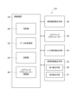
- FIG. 2 is a block diagram showing the configuration of the control system 1 in the saddle-ride type vehicle 10 according to this embodiment.
- the control device 34 includes a vehicle speed sensor 36 that detects the speed of the vehicle 10, a steering actuator 30, a vehicle behavior detection means 32 that detects the behavior of the vehicle 10, and a turn signal operation detection means 54 that detects the turn signal operation performed by the occupant U. , are connected via the data transmission/reception unit 42 .
- the winker operation includes a winker lighting operation and a winker extinguishing operation.
- the control device 34 has a data transmission/reception section 42 including an interface circuit for transferring data between the CPU and other devices, and a storage section 44 for storing data.
- a storage device included in the storage unit 44 may be, for example, an SSD (Solid State Device).
- the control device 34 operates in a first control mode in which a predetermined steering torque is applied to the suspension device 31 according to the roll angular velocity detected by the first detection means 56, and a second steering torque smaller than the first steering torque. parameters and control programs for each control are stored in the storage unit 44 .
- the control device 34 also has a determination unit 40 that determines whether or not a predetermined condition for switching between the first control mode and the second control mode is satisfied.
- the CPU implements the functions of the determination unit 40 by executing the programs stored in the storage unit 44 .
- the determination unit 40 determines that the predetermined condition is satisfied when the vehicle behavior detection means 32 detects a physical quantity that satisfies the predetermined condition. Details of the determination process will be described later. Further, the CPU executes the program stored in the storage unit 44 to realize the function of the actuator control unit 46 that controls the steering actuator 30 that applies torque in the steering direction to the suspension device 31 that supports the steering wheel 21. do.
- FIG. 3 is a flow chart of control processing in the saddle-ride type vehicle 10 according to the present embodiment.
- the control device 34 performs control to apply a predetermined first steering torque to the suspension device 31 according to the roll angular velocity detected by the first detection means 56 while the vehicle is running.
- the control device 34 performs control to apply a predetermined second steering torque that is smaller than the first steering torque (see FIG. 6, which will be described later).
- control device 34 performs control according to the first control mode (step SA1). Specifically, the control device 34 performs attitude stabilization control, and performs steering assist to keep the vehicle upright with respect to the road surface.
- the control device 34 calculates the vehicle speed from the information detected using the vehicle speed sensor 36, and acquires the roll angular speed using the first detection means 56 (step SA2). Of course, the roll angular velocity may be calculated by the controller 34 calculating the roll angle detected by the second detection means 57 .
- the control device 34 detects the turn-on and turn-off operations of the winkers by the occupant U (step SA3).
- the determination unit 40 determines whether or not the vehicle speed is less than a predetermined first threshold (step SA4).
- the first threshold is pre-stored in the storage unit 44 . For the first threshold value, a value corresponding to the roll angular velocity may be stored in the storage unit 44 in the form of a lookup table.
- the control device 34 switches control from the first control mode to the second control mode based on the vehicle speed and the roll angle of the vehicle. Specifically, when it is detected that the turn signals are turned on, the control device 34 switches the vehicle control from the first control mode to the second control mode when a predetermined condition is satisfied.
- the predetermined condition is a condition that the blinker lighting operation is performed when turning operations in mutually different directions are continuously performed.
- the fact that turning operations in mutually different directions are continuously performed means that when two turning operations are performed, the first turning operation and the second turning operation are continuously performed.
- a brief operation may be included between one turning operation and a second turning operation.
- Another operation is a steering operation that is performed in a shorter time than the first turning operation and the second turning operation. etc.
- a turning operation is a steering operation that changes the direction in which the vehicle travels, such as a left turn operation or a right turn operation.
- the first threshold is, for example, 10 km/h.
- step SA4 determines that the vehicle speed is greater than or equal to the first threshold
- step SA5 determines that the roll angular velocity has not reversed in polarity
- step SA6 determines that the blinker lighting operation is not performed
- the determination section 40 determines whether or not the blinker has been turned off (step SA8). Specifically, the control device 34 detects a winker operation from the winker operation detection means 54, and the determination unit 40 makes a determination. If the blinker has not been turned off (step SA8: NO), the determination unit 40 determines whether or not the vehicle speed is equal to or higher than the second threshold (step SA9). Specifically, the control device 34 calculates the vehicle speed from information detected using the vehicle speed sensor 36, and determines whether or not the vehicle speed is equal to or higher than the second threshold. When the determination unit 40 determines that the vehicle speed is equal to or higher than the second threshold (step SA9: YES), the control device 34 switches control to the first control mode (SA10) and returns to step SA2.
- the second threshold is, for example, 20 km/h.
- the second threshold is stored in the storage unit 44 in advance.
- step SA8 determines that the blinker has been turned off
- step SA10 the control device 34 switches the vehicle control to the first control mode (SA10) and returns to step SA2.
- the determination unit 40 may detect the control result of automatically turning off the winkers and make the above determination.
- step SA9 NO
- the process returns to step SA8.
- control device 34 switches the vehicle control from the second control mode to the first control mode when it detects that the turn signals are turned off. Further, when the turn signal is turned off and the vehicle speed is equal to or higher than the predetermined second threshold, the control device 34 switches from the second control mode to the first control mode.
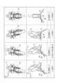
- FIG. 4 is a conceptual diagram illustrating an example of the relationship between turn signal lighting operation, turning off operation, and control mode.
- the top row is a front view of the saddle-ride type vehicle 10, and simply shows the steering wheel operation by the passenger U and the behavior of the vehicle 10 associated therewith.
- the second line is a top view of the front portion of the saddle-ride type vehicle 10 .
- a steering wheel operation by an occupant U, and an operation of turning on and off the winkers are shown.
- the vehicle 10 is running under the control in the first control mode, it is assumed that the occupant U turns on the turn signal in the direction of the arrow when turning left ((1) when turning left).
- the steering wheel 21 is steered leftward and the weight of the occupant U shifts, causing the vehicle to roll leftward and the occupant U to turn on the left winker.
- the occupant U operates the turn signal so that the right turn signal lights up, and the occupant U starts steering operation, that is, turning back to right turn ((2) During turning back to right turn) case).
- the control device 34 switches the control mode from the first control mode to the second control mode when a predetermined condition is satisfied. While the vehicle is turning right and turning right ((3) right turning), the control device 34 continues control in the second control mode. Then, when the right turn is completed, the occupant U turns off the winkers, and the vehicle speed exceeds a predetermined speed, the control device 34 performs control in the first control mode ((4) Right turn completion). case).
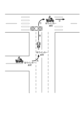
- FIG. 5 is an explanatory diagram comparing the control by the control device 34 shown in FIG. 4 and the movement of the vehicle 10.
- the passenger U causes the vehicle 10 to turn left.
- the occupant U turns on the left winker, and the controller 34 controls the vehicle 10 in the first control mode (area A).
- the control device 34 switches the control mode from the first control mode to the second control mode to control the vehicle 10 in the second control mode (area B).
- the vehicle 10 would be more upright than the occupant U thinks, and there is a possibility that the occupant U would feel uncomfortable.
- the right blinker is turned off (area C).
- the control device 34 switches the control mode from the second control mode to the first control mode, and controls the vehicle 10 in the first control mode (area D).
- FIG. 6 is a graph illustrating the relationship between steering torque and roll angular velocity.
- the vertical axis is the magnitude of the steering torque applied to the suspension device 31 by the steering actuator 30, and the horizontal axis is the roll angular velocity detected by the first detection means 56.
- the control device 34 controls the vehicle 10 in the second control mode. small. Assuming that the occupant U loosens the force for holding the steering angle by operating the blinker, the steering control is weakened so as not to cause the vehicle body to be raised too much so that the vehicle cannot be steered.
- the control that weakens the steering control includes control that does not apply the steering torque in some cases.
- the relationship between the applied steering torque and roll angular velocity dependence can be set variously depending on the type of vehicle and desired performance. Further, the control device 34 may perform control to change the roll angular velocity dependence of the steering torque to be applied based on the vehicle speed or the roll angle, for example.
- FIG. 7 is a block diagram showing the configuration of control system 101 in saddle-ride type vehicle 10 according to the second embodiment.
- the configuration of the saddle-ride type vehicle 10 according to the second embodiment is the same as that of the above-described embodiment (hereinafter referred to as the first embodiment), so detailed description thereof will be omitted.
- the control system 101 includes shift operation detection means 60 for detecting a shift operation performed by the passenger U. Specifically, the shift operation includes the disengaging operation and connecting operation of the clutch performed by the passenger U.
- the shift operation detection means 60 is connected to the control device 34 via the data transmission/reception section 42 .
- the detected shift operation is used for determination by the determination unit 40 (see FIG. 8, which will be described later).
- the control device 34 has a shift operation timing recording section (not shown) that records the timing of each shift operation.
- Other configurations of the control system 101 are the same as those of the control system 1 according to the first embodiment, so description thereof is omitted.
- FIG. 8 is a flow chart of control processing in the saddle-ride type vehicle 10 according to the second embodiment.
- the control modes of the control performed by the control device 34 of the saddle-ride type vehicle 10 according to the present embodiment during travel include a predetermined first control mode and a predetermined second control mode.
- the control device 34 performs the first control of applying a predetermined steering torque to the suspension device 31 according to the roll angular velocity detected by the first detection means 56 while the vehicle is running.
- the control device 34 performs the second control to apply the second steering torque smaller than the first steering torque (see FIG. 6 described above).
- control device 34 performs vehicle control in the first control mode (step SB1). At this time, the control device 34 performs posture stabilization control and performs steering assist to keep the vehicle in an upright state with respect to the road surface.
- the control device 34 calculates the vehicle speed from information detected using the vehicle speed sensor 36, and acquires the roll angle using the second detection means 57 (step SB2).
- the roll angle may be calculated by the control device 34 from the roll angular velocity and the like detected by the first detection means 56 .
- the control device 34 detects the shift operation by the passenger U (step SB3).
- the determination unit 40 determines whether or not the occupant U has performed an operation to disengage the clutch using a clutch lever 62, which is shift operation means, which will be described later (SB4).
- the determination unit 40 determines whether the vehicle speed is less than a predetermined third threshold (step SA4).
- the third threshold is pre-stored in the storage unit 44 .
- a value corresponding to the roll angle may be stored in the storage unit 44 in the form of a lookup table.
- step SB6 determines whether the roll angle detected by the first detection means 56 is equal to or greater than a predetermined angle.
- step SB6 determines whether the roll angle detected by the first detection means 56 is equal to or greater than a predetermined angle.
- step SB7 determines whether the roll angle detected by the first detection means 56 is equal to or greater than a predetermined angle.
- the saddle-ride type vehicle 10 includes shift operation detection means 60 for detecting that a shift operation has been performed, and the shift operation detection means (60) detects that a shift operation has been performed.
- the control device 34 switches from the first control mode to the second control mode when the vehicle 10 satisfies a predetermined condition. Specifically, the control device 34 switches from the first control mode to the second control mode based on the vehicle speed and the roll angle.
- the predetermined condition is, for example, when turning operations in mutually different directions are continuously performed, the vehicle speed becomes lower than the predetermined speed, and the roll angle becomes equal to or greater than the predetermined angle.
- the condition is that U has operated the clutch lever 62 to disengage the clutch.
- the third threshold is, for example, 30 km/h.
- the predetermined angle for the roll angle is, for example, 15 degrees.
- step SB8 YES
- the control device 34 switches the control mode from the second control mode to the first control mode, and after performing the first control of the vehicle (step SB10 ) and return to step SB2. If the determination unit 40 determines that the predetermined time has passed since the most recent shift operation (step SB9: NO), the process returns to step SB8.
- the control device 34 when the shift operation detection means 60 detects that the shift operation has ended, switches from the second control mode to the first control mode. switch to Further, when a predetermined time has passed since the shift operation, the control device 34 switches from the second control mode to the first control mode.
- the predetermined time is, for example, 2 seconds.
- the predetermined time is stored in the storage unit 44 in advance.
- FIG. 9 is a conceptual diagram illustrating the relationship between shift operations and control modes.
- the top row is a front view of the saddle-ride type vehicle 10, and simply shows the steering wheel operation by the passenger U and the behavior of the vehicle 10 associated therewith.
- the second line is a top view of the front portion of the saddle-ride type vehicle 10 .
- a steering wheel operation by an occupant U, and an operation of turning on and off the winkers are shown. Assume that the vehicle 10 turns left while it is traveling under the control of the first control mode ((1) when turning left). At this time, the steering wheel 21 is steered leftward and the weight of the occupant U shifts, causing the vehicle to roll leftward.
- the control device 34 switches the vehicle control from the first control mode to the second control mode.
- predetermined conditions such as when the clutch lever 62 is opened and the clutch is engaged while turning right and turning right ((3) Right turn, clutch engagement)
- the control device 34 switches from the second control mode to the first control mode, and controls the vehicle 10 in the first control mode.
- a steering actuator that applies torque in a steering direction to a suspension device that supports steered wheels, first detection means that detects the roll angular velocity of the vehicle, and the roll angular velocity detected by the first detection means and a control device that controls the steering actuator to apply the torque to the suspension device, wherein the control device controls the control mode to apply a predetermined first steering torque. and a second control mode in which control is performed to apply a second steering torque smaller than the first steering torque, and when a predetermined condition is satisfied, the first control mode and the and the second control mode.
- the steering assist when the predetermined condition is satisfied, the steering assist can be performed with a smaller torque than the steering torque for the posture stabilization control during normal running. For this reason, it is possible to prevent the occupant from feeling uncomfortable when continuously performing turning operations in mutually different directions.
- (Arrangement 2) A second detection means for detecting the roll angle of the vehicle, and a vehicle speed detection means for detecting the speed of the vehicle, wherein the predetermined condition is the roll angle, the roll angular velocity, or the A saddle-riding vehicle as set forth in claim 1, including at least one of vehicle speeds.
- the vehicle speed is slow, it may be difficult for the occupant to stabilize the posture.
- the roll angle is large or when the roll angular velocity is large, it may be difficult for the occupant to stabilize the posture.
- the control of the steering torque to be applied can be changed according to the magnitude of the vehicle speed, the magnitude of the roll angle, or the magnitude of the roll angular velocity.
- a saddle-ride type vehicle that can easily maintain a straight posture is realized.
- the control device can switch from the first control mode with large steering torque, which is normal posture stabilization control, to the second control mode accompanied by steering assist with small steering torque during the turn signal lighting operation. can.
- a saddle-riding type vehicle is realized in which it is easy to maintain a stable posture without causing discomfort to the occupant during travel.
- (Configuration 4) The control device switches from the second control mode to the first control mode when the winker operation detection means detects that the winker is turned off. 3.
- Configuration 5 Any one of configurations 2 to 4, wherein the control device switches from the second control mode to the first control mode when the vehicle speed exceeds a predetermined speed.
- a saddle-riding vehicle as described. When the speed of the vehicle exceeds a certain level, the attitude of the vehicle becomes more stable. According to such a configuration, the control device can switch from the second control mode with small steering torque to the first control mode with steering assist with large steering torque according to the vehicle speed. As a result, a saddle-riding type vehicle is realized in which it is easy to maintain a stable posture without causing discomfort to the occupant during travel.
- a shift operation detection means for detecting a shift operation is provided, and when the shift operation detection means detects that the predetermined condition is satisfied and the shift operation is started, the control device , the straddle-type vehicle according to configuration 2, wherein the first control mode is switched to the second control mode.
- the shift operation detection means detects that the predetermined condition is satisfied and the shift operation is started, the control device , the straddle-type vehicle according to configuration 2, wherein the first control mode is switched to the second control mode.
- the control device can switch from the first control mode with large steering torque, which is normal posture stabilization control, to the second control mode with steering assist with small steering torque during the shift operation. .
- a saddle-riding type vehicle is realized in which it is easy to maintain a stable posture without causing discomfort to the occupant during travel.
- the processing of the control device 34 can be divided into more processing units according to the processing content, or can be divided so that one processing unit includes more processing. Also, the processing order of the above flowchart is not limited to the illustrated example.
Landscapes
- Engineering & Computer Science (AREA)
- Mechanical Engineering (AREA)
- Transportation (AREA)
- Chemical & Material Sciences (AREA)
- Combustion & Propulsion (AREA)
- Automation & Control Theory (AREA)
- Steering Control In Accordance With Driving Conditions (AREA)
- Automatic Cycles, And Cycles In General (AREA)
Abstract
Description
本発明は、上述した事情を鑑みてなされたものであり、互いに異なる方向への旋回操作を連続して行う際の違和感を抑えることができる鞍乗り型車両を提供することを目的とする。
なお、この明細書には、2021年11月26日に出願された日本国特許出願・特願2021-192347号の全ての内容が含まれるものとする。
図1は、本発明の実施の形態に係る鞍乗り型車両10の側面図である。
鞍乗り型車両10は、車体フレーム11と、車体フレーム11に支持されるパワーユニット12と、前輪13を操舵自在に支持するフロントフォーク14と、後輪15を支持するスイングアーム16と、乗員用のシート17とを備える車両である。
鞍乗り型車両10は、乗員がシート17に跨るようにして着座する車両である。シート17は、車体フレーム11の後部の上方に設けられる。
シート17は、リアフレーム20に支持される。
後輪15は、スイングアーム16の後端部に設けられる車軸15aに支持される。
パワーユニット12は、内燃機関である。パワーユニット12は、クランクケース23と、往復運動するピストンを収容するシリンダー部24とを備える。シリンダー部24の排気ポートには、排気装置25が接続される。
パワーユニット12の出力は、パワーユニット12と後輪15とを接続する駆動力伝達部材によって後輪15に伝達される。
フロントフェンダー26は、フロントフォーク14に取り付けられる。リアフェンダー27及びステップ28は、シート17よりも下方に設けられる。燃料タンク29は、車体フレーム11に支持される。
車両速度を検出する方法としては、例えばマイクロ波やレーザー光で検出する方法等であってよい。また車輪速度を検出して車両速度を算出してもよい。
なお、ウィンカー操作にはウィンカー点灯操作及びウィンカー消灯操作が含まれる。
制御装置34は、第1検出手段56によって検出されたロール角速度に応じて懸架装置31に所定の操舵トルクを付与する制御を行う第1制御モードと、第1操舵トルクよりも小さい第2操舵トルクを付与する制御を行う第2制御モードとを有し、それぞれの制御のためのパラメーターや制御プログラムは記憶部44に記憶される。また制御装置34は、第1制御モードと第2制御モードとを切り替える所定の条件を満たしたか否かを判定する判定部40を有する。
また、CPUは、記憶部44に記憶されたプログラムを実行することで、ハンドル21を支持する懸架装置31に操舵方向のトルクを付与するステアリングアクチュエーター30の制御を行うアクチュエーター制御部46の機能を実現する。
なお本明細書において旋回操作とは左折操作又は右折操作といったように、車両が進行する方向を変えるハンドル操作のことである。
判定部40が、車両速度は第2閾値未満であると判定した場合(ステップSA9:NO)、ステップSA8に戻る。
車両10が第1制御モードで制御をされて走行している場合、左折したときに、乗員Uがウィンカーを矢印方向に操作する点灯操作をしたとする((1)左折中の場合)。このときハンドル21が左方に転舵され、且つ、乗員Uが体重移動することで車両は左方向にロールし、左方のウィンカーが点灯するように乗員Uが操作する。続けて右折のために乗員Uがウィンカーを右方のウィンカーが点灯するように操作をして、乗員Uが転舵動作、すなわち右折への切り返しを開始する((2)右折への切り返し中の場合)。このとき制御装置34は、所定の条件が満たされている場合制御モードを第1制御モードから第2制御モードに切り替える。右旋回をして右折している間((3)右折中の場合)、制御装置34は第2制御モードで制御を続ける。そして右折が終了して乗員Uがウィンカーの消灯操作を行い、且つ、車両が所定の速度以上になったならば、制御装置34は第1制御モードでの制御を行う((4)右折終了の場合)。
なお各制御モードについて、付与される操舵トルクとロール角速度依存の関係は、車両の種類や求める性能で様々に設定し得る。また例えば車両速度やロール角に基づいて、付与される操舵トルクのロール角速度依存性を変更させる制御を制御装置34が行ってもよい。
図7は、実施の形態2に係る鞍乗り型車両10における制御システム101の構成を示すブロック図である。本実施の形態2に係る鞍乗り型車両10の構成は、上述の実施の形態(以下、実施の形態1と呼ぶ)の構成と同様なので詳細な記載を省略する。
制御システム101は、乗員Uが行うシフト操作を検出するシフト操作検出手段60を備える。具体的にシフト操作は、乗員Uが行うクラッチの切断動作及び接続動作を含む。シフト操作検出手段60は、データ送受信部42を介して制御装置34に接続される。検出されたシフト操作は、判定部40での判定に用いられる(後述する図8参照)。制御装置34は、それぞれのシフト操作がされたタイミングを記録するシフト操作タイミング記録部(不図示)を有する。
なお制御システム101のその他の構成は、実施の形態1に係る制御システム1と同様なので記載を省略する。
クラッチは切断されていないと判定部40が判定した場合(ステップSB4:NO)、ステップSB2に戻る。また判定部40が車両速度は第3閾値以上であると判定した場合(ステップSB5:NO)、ステップSB2に戻る。判定部40がロール角は所定の角度未満であると判定した場合(ステップSB6:NO)、ステップSB2に戻る。
クラッチが接続されていると判定部40が判定した場合(ステップSB8:YES)、制御装置34は制御モードを第2制御モードから第1制御モードに切替え、車両を第1制御した後(ステップSB10)、ステップSB2に戻る。また直近のシフト操作から所定の時間が経過したと、判定部40が判定した場合(ステップSB9:NO)、ステップSB8に戻る。
車両10が第1制御モードで制御されて走行している場合に左折したとする((1)左折中の場合)。このときハンドル21が左方に転舵され、且つ、乗員Uが体重移動することで車両は左方向にロールする。続けてシフト操作のために乗員Uがクラッチレバー62を閉じる操作をして、乗員Uが転舵動作、すなわち右折への切り替えしを開始する((2)右折への切返し中、クラッチ切断の場合)。このとき制御装置34は、所定の条件が満たされている場合、車両制御を第1制御モードから第2制御に切り替える。右旋回をして右折している間((3)右折中、クラッチ接続の場合)、クラッチレバー62が開かれてクラッチが接続された場合等、所定の条件が満たされたとき、制御装置34は、第2制御モードから第1制御モードに切り替えて、第1制御モードで車両10の制御を行う。
上記実施の形態は、以下の構成をサポートする。
互いに異なる方向への旋回操作が連続して行われる場合、直立状態を維持しようとする操舵アシストが行われると、乗員に違和感を持たせる虞がある。このような構成によれば、所定の条件が満たされる場合には、通常走行中の姿勢安定制御のための操舵トルクよりも小さなトルクで操舵アシストを行うことができる。このため、乗員に互いに異なる方向への旋回操作を連続して行う際の違和感を抑えることができる。
車両速度が遅い場合には、乗員による姿勢安定は難しくなる可能性がある。またロール角が大きい場合や、ロール角速度が大きい場合にも、乗員による姿勢安定は難しい可能性がある。このような構成によれば、車両速度の高低、ロール角の大小、又はロール角速度の大小に応じて付与する操舵トルクの制御を変えられるので、乗員に走行上の違和感を生じさせることなく、安定した姿勢を保ちやすい鞍乗り型車両が実現される。
ウィンカーの点灯操作を行う際には、乗員がハンドルを把持する力が低下するため、ハンドルの舵角を保ち難くなる。そのため旋回操作する場合、ウィンカーの点灯操作を行うときに、通常走行中と同じ姿勢安定制御のための操舵アシストがなされるとき、乗員に走行上の違和感を生じさせる虞がある。このような構成によれば、ウィンカー点灯操作中に制御装置が、通常の姿勢安定制御である操舵トルクの大きな第1制御モードから、操舵トルクの小さな操舵アシストを伴う第2制御モードに切り替えることができる。このため乗員に走行上の違和感を生じさせることなく、安定した姿勢を保ちやすい鞍乗り型車両が実現される。
ウィンカーの消灯操作がされた後には、乗員がハンドルを把持する力が回復する。その場合、通常走行中と同じ姿勢安定制御のための操舵アシストがなされる方が好ましい。このような構成によれば、制御装置は、操舵トルクの小さな第2制御モードから、操舵トルクの大きな操舵アシストを伴う第1制御モードに切り替えることができる。このため乗員に走行上の違和感を生じさせることなく、安定した姿勢を保ちやすい鞍乗り型車両が実現される。
車両の速度がある程度以上になれば、車両の姿勢は安定しやすくなる。このような構成によれば、制御装置は、車両速度に応じて、操舵トルクの小さな第2制御モードから、操舵トルクの大きな操舵アシストを伴う第1制御モードに切り替えることができる。このため乗員に走行上の違和感を生じさせることなく、安定した姿勢を保ちやすい鞍乗り型車両が実現される。
シフト操作、具体的にはクラッチレバーの開閉を行う際には、乗員がハンドルを把持する力が低下するため、ハンドルの舵角を保ち難くなる。そのため旋回中に通常走行中と同じ姿勢安定制御のための操舵アシストがなされると、乗員に走行上の違和感を生じさせる虞がある。このような構成によれば、シフト操作中に制御装置が、通常の姿勢安定制御である操舵トルクの大きな第1制御モードから、操舵トルクの小さな操舵アシストを伴う第2制御モードに切り替えることができる。このため乗員に走行上の違和感を生じさせることなく、安定した姿勢を保ちやすい鞍乗り型車両が実現される。
シフト操作開始からある程度の時間が経過すれば、シフトショックの影響はなくなると考えられる。このような構成によれば、シフト操作開始後、所定の時間が経過したときに、制御装置は操舵トルクの小さな第2制御モードから、操舵トルクの大きな操舵アシストを伴う第1制御モードに切り替えることができる。このため乗員に走行上の違和感を生じさせることなく、安定した姿勢を保ちやすい鞍乗り型車両が実現される。
シフト操作が終了、すなわちクラッチが接続された場合には、クラッチレバーの開閉操作が終了して、乗員がハンドルを把持する力は回復する。したがって姿勢安定制御のための操舵アシストがなされても問題なく対応ができるようになる可能性が高い。その場合、通常走行中と同じ姿勢安定制御のための操舵アシストがなされる方が好ましい。このような構成によれば、制御装置は、操舵トルクの小さな第2制御モードから、操舵トルクの大きな操舵アシストを伴う第1制御モードに切り替えることができる。このため乗員に走行上の違和感を生じさせることなく、安定した姿勢を保ちやすい鞍乗り型車両が実現される。
また図3、及び図8に示すフローチャートの処理単位は、制御装置34の処理を理解容易にするために、主な処理内容に応じて分割したものであり、処理単位の分割の仕方や名称によって本開示が制限されることはない。
13 前輪(操舵輪)
30 ステアリングアクチュエーター
31 懸架装置
34 制御装置
36 車両速度センサー(車両速度検出手段)
40 判定部
46 ステアリングアクチュエーター制御部
54 ウィンカー操作検出手段
56 第1検出手段
57 第2検出手段
60 シフト操作検出手段
Claims (8)
- 操舵輪(13)を支持する懸架装置(31)に操舵方向のトルクを付与するステアリングアクチュエーター(30)と、
車両(10)のロール角速度を検出する第1検出手段(56)と、
前記第1検出手段(56)によって検出された前記ロール角速度に基づいて、前記ステアリングアクチュエーター(30)を制御して前記トルクを前記懸架装置(31)に付与する制御を行う制御装置(34)と、
を備え、
前記制御装置(34)は、
前記制御のモードに、所定の第1操舵トルクを付与する制御を行う第1制御モードと、前記第1操舵トルクよりも小さい第2操舵トルクを付与する制御を行う第2制御モードと、を含み、
所定の条件が満たされた場合に、前記第1制御モードと、前記第2制御モードとを切り替えることを特徴とする鞍乗り型車両。 - 前記車両のロール角を検出する第2検出手段(56)と、
前記車両(10)の速度を検出する車両速度検出手段(36)と、
を備え、
前記所定の条件は、前記ロール角、前記ロール角速度、又は前記車両速度のうちの少なくとも一つを含むことを特徴とする請求項1に記載の鞍乗り型車両。 - ウィンカーの点灯操作及び消灯操作を検出するウィンカー操作検出手段(54)を備え、
前記所定の条件が満たされ、
且つ、
前記ウィンカー操作検出手段(54)が、ウィンカーの点灯操作がなされたことを検出した場合に、
前記制御装置(34)は、前記第1制御モードから前記第2制御モードに切り替えることを特徴とする請求項2に記載の鞍乗り型車両。 - 前記ウィンカー操作検出手段(54)が、前記ウィンカーの消灯操作がなされたことを検出した場合に、前記制御装置(34)は、前記第2制御モードから前記第1制御モードに切り替えることを特徴とする請求項3に記載の鞍乗り型車両。
- 前記車両速度が所定の速度以上となった場合に、前記制御装置(34)は、前記第2制御モードから前記第1制御モードに切り替えることを特徴とする請求項2乃至請求項4のいずれかに記載の鞍乗り型車両。
- シフト操作を検出するシフト操作検出手段(60)を備え、
前記所定の条件が満たされ、
且つ、
前記シフト操作が開始されたことを、前記シフト操作検出手段(60)が検出した場合、
前記制御装置(34)は、前記第1制御モードから前記第2制御モードに切り替えることを特徴とする請求項2に記載の鞍乗り型車両。 - 前記制御装置(34)は、前記シフト操作が開始されたことを、前記シフト操作検出手段(60)が検出した場合、所定の時間が経過したときに、前記第2制御モードから前記第1制御モードに切り替えることを特徴とする請求項6に記載の鞍乗り型車両。
- 前記シフト操作が終了されたことを、前記シフト操作検出手段(60)が検出した場合、前記制御装置(34)は、前記第2制御モードから前記第1制御モードに切り替えることを特徴とする請求項6又は請求項7に記載の鞍乗り型車両。
Priority Applications (2)
| Application Number | Priority Date | Filing Date | Title |
|---|---|---|---|
| US18/712,033 US12491864B2 (en) | 2021-11-26 | 2022-09-05 | Saddle ride type vehicle |
| DE212022000332.2U DE212022000332U1 (de) | 2021-11-26 | 2022-09-05 | Sattelaufsitzart-Fahrzeug |
Applications Claiming Priority (2)
| Application Number | Priority Date | Filing Date | Title |
|---|---|---|---|
| JP2021-192347 | 2021-11-26 | ||
| JP2021192347 | 2021-11-26 |
Publications (1)
| Publication Number | Publication Date |
|---|---|
| WO2023095412A1 true WO2023095412A1 (ja) | 2023-06-01 |
Family
ID=86539138
Family Applications (1)
| Application Number | Title | Priority Date | Filing Date |
|---|---|---|---|
| PCT/JP2022/033310 Ceased WO2023095412A1 (ja) | 2021-11-26 | 2022-09-05 | 鞍乗り型車両 |
Country Status (3)
| Country | Link |
|---|---|
| US (1) | US12491864B2 (ja) |
| DE (1) | DE212022000332U1 (ja) |
| WO (1) | WO2023095412A1 (ja) |
Cited By (2)
| Publication number | Priority date | Publication date | Assignee | Title |
|---|---|---|---|---|
| JP2025064657A (ja) * | 2023-10-06 | 2025-04-17 | ヤマハ発動機株式会社 | 二輪車両のステアリング制御システム |
| JP2025064656A (ja) * | 2023-10-06 | 2025-04-17 | ヤマハ発動機株式会社 | 二輪車両のステアリング制御システム |
Citations (4)
| Publication number | Priority date | Publication date | Assignee | Title |
|---|---|---|---|---|
| JP2019119446A (ja) * | 2018-01-05 | 2019-07-22 | ヤマハ発動機株式会社 | 車両 |
| JP6646682B2 (ja) * | 2015-11-20 | 2020-02-14 | ヤマハ発動機株式会社 | リーン車両 |
| JP2020158067A (ja) * | 2019-03-28 | 2020-10-01 | 本田技研工業株式会社 | 鞍乗り型車両の姿勢制御装置 |
| WO2021065780A1 (ja) * | 2019-09-30 | 2021-04-08 | 本田技研工業株式会社 | 鞍乗り型車両の操舵アシスト装置 |
Family Cites Families (4)
| Publication number | Priority date | Publication date | Assignee | Title |
|---|---|---|---|---|
| JP5405969B2 (ja) * | 2009-09-30 | 2014-02-05 | 本田技研工業株式会社 | 自動二輪車の操舵装置 |
| EP3666634B1 (en) * | 2017-11-01 | 2022-03-30 | Yamaha Hatsudoki Kabushiki Kaisha | Leaning vehicle |
| JP7014760B2 (ja) | 2019-09-30 | 2022-02-01 | 本田技研工業株式会社 | 鞍乗り型車両の操舵アシスト装置 |
| JP7592983B2 (ja) | 2020-06-05 | 2024-12-03 | 株式会社Gsユアサ | 蓄電素子の製造方法、及び、蓄電素子 |
-
2022
- 2022-09-05 US US18/712,033 patent/US12491864B2/en active Active
- 2022-09-05 DE DE212022000332.2U patent/DE212022000332U1/de active Active
- 2022-09-05 WO PCT/JP2022/033310 patent/WO2023095412A1/ja not_active Ceased
Patent Citations (4)
| Publication number | Priority date | Publication date | Assignee | Title |
|---|---|---|---|---|
| JP6646682B2 (ja) * | 2015-11-20 | 2020-02-14 | ヤマハ発動機株式会社 | リーン車両 |
| JP2019119446A (ja) * | 2018-01-05 | 2019-07-22 | ヤマハ発動機株式会社 | 車両 |
| JP2020158067A (ja) * | 2019-03-28 | 2020-10-01 | 本田技研工業株式会社 | 鞍乗り型車両の姿勢制御装置 |
| WO2021065780A1 (ja) * | 2019-09-30 | 2021-04-08 | 本田技研工業株式会社 | 鞍乗り型車両の操舵アシスト装置 |
Cited By (4)
| Publication number | Priority date | Publication date | Assignee | Title |
|---|---|---|---|---|
| JP2025064657A (ja) * | 2023-10-06 | 2025-04-17 | ヤマハ発動機株式会社 | 二輪車両のステアリング制御システム |
| JP2025064656A (ja) * | 2023-10-06 | 2025-04-17 | ヤマハ発動機株式会社 | 二輪車両のステアリング制御システム |
| JP7742387B2 (ja) | 2023-10-06 | 2025-09-19 | ヤマハ発動機株式会社 | 二輪車両のステアリング制御システム |
| JP7742388B2 (ja) | 2023-10-06 | 2025-09-19 | ヤマハ発動機株式会社 | 二輪車両のステアリング制御システム |
Also Published As
| Publication number | Publication date |
|---|---|
| US12491864B2 (en) | 2025-12-09 |
| US20250018929A1 (en) | 2025-01-16 |
| DE212022000332U1 (de) | 2024-09-02 |
Similar Documents
| Publication | Publication Date | Title |
|---|---|---|
| JP7285673B2 (ja) | 鞍乗り型車両の姿勢制御装置 | |
| JP6099600B2 (ja) | 車両用操舵装置 | |
| JP6213904B1 (ja) | 車両用挙動制御装置 | |
| CN106553690B (zh) | 车辆用转向装置 | |
| CN114450217B (zh) | 跨骑型车辆的转向辅助装置 | |
| JP4333729B2 (ja) | 車両挙動制御装置 | |
| JP7253422B2 (ja) | 鞍乗り型車両の自動制御装置 | |
| US11654893B2 (en) | Controller and control method | |
| WO2023095412A1 (ja) | 鞍乗り型車両 | |
| JP2005193788A (ja) | 雪上車の電動パワーステアリング装置 | |
| JP7414838B2 (ja) | 鞍乗り型車両 | |
| TWI832423B (zh) | 傾斜控制裝置及傾斜車輛 | |
| US20220203979A1 (en) | Controller and control method | |
| JP4188740B2 (ja) | 自動車運転支援装置 | |
| JP6754466B2 (ja) | 車両用操舵装置 | |
| JP7262603B2 (ja) | 鞍乗り型車両の操舵アシスト装置 | |
| JP6388259B2 (ja) | 車両用挙動制御装置 | |
| JP4442270B2 (ja) | 車両用操舵装置 | |
| WO2022137819A1 (ja) | 車両 | |
| JP7621525B2 (ja) | 鞍乗り型車両及び触覚刺激システム | |
| JP6521496B1 (ja) | 車両の挙動制御装置 | |
| WO2024203085A1 (ja) | 車両制御システム、及び鞍乗型車両 | |
| JP2007038941A (ja) | 車両用パワーステアリング装置 | |
| JP5119691B2 (ja) | 操舵制御装置 | |
| JP2017001415A (ja) | 車両制御装置 |
Legal Events
| Date | Code | Title | Description |
|---|---|---|---|
| 121 | Ep: the epo has been informed by wipo that ep was designated in this application |
Ref document number: 22898197 Country of ref document: EP Kind code of ref document: A1 |
|
| WWE | Wipo information: entry into national phase |
Ref document number: 18712033 Country of ref document: US |
|
| WWE | Wipo information: entry into national phase |
Ref document number: 212022000332 Country of ref document: DE |
|
| 122 | Ep: pct application non-entry in european phase |
Ref document number: 22898197 Country of ref document: EP Kind code of ref document: A1 |
|
| NENP | Non-entry into the national phase |
Ref country code: JP |