WO2023095256A1 - 無停電電源装置 - Google Patents
無停電電源装置 Download PDFInfo
- Publication number
- WO2023095256A1 WO2023095256A1 PCT/JP2021/043240 JP2021043240W WO2023095256A1 WO 2023095256 A1 WO2023095256 A1 WO 2023095256A1 JP 2021043240 W JP2021043240 W JP 2021043240W WO 2023095256 A1 WO2023095256 A1 WO 2023095256A1
- Authority
- WO
- WIPO (PCT)
- Prior art keywords
- current
- fan
- cooling fan
- inverter
- power supply
- Prior art date
- Legal status (The legal status is an assumption and is not a legal conclusion. Google has not performed a legal analysis and makes no representation as to the accuracy of the status listed.)
- Ceased
Links
Images



Classifications
-
- H—ELECTRICITY
- H02—GENERATION; CONVERSION OR DISTRIBUTION OF ELECTRIC POWER
- H02J—ELECTRIC POWER NETWORKS; CIRCUIT ARRANGEMENTS OR SYSTEMS FOR SUPPLYING OR DISTRIBUTING ELECTRIC POWER; SYSTEMS FOR STORING ELECTRIC ENERGY
- H02J9/00—Circuit arrangements for emergency or stand-by power supply, e.g. for emergency lighting
- H02J9/04—Circuit arrangements for emergency or stand-by power supply, e.g. for emergency lighting in which the distribution system is disconnected from the normal source and connected to a standby source
- H02J9/06—Circuit arrangements for emergency or stand-by power supply, e.g. for emergency lighting in which the distribution system is disconnected from the normal source and connected to a standby source with automatic change-over, e.g. UPS systems
Definitions
- the present disclosure relates to an uninterruptible power supply.
- An uninterruptible power supply generally consists of a converter that converts commercial AC power to DC power, a power storage device such as a battery, and DC power generated by the converter or converted to AC power from the power storage device. and an inverter that supplies the load with a power supply.
- An uninterruptible power supply may also include a chopper that converts the DC power of the power storage device.
- the uninterruptible power supply includes a cooling fan for cooling the inside of the housing in which the main body of the uninterruptible power supply is housed.
- Patent Document 1 discloses a FAN current detection unit that converts a current flowing through a FAN into a voltage signal and outputs the voltage signal, and converts a voltage signal waveform detected by the FAN current detection unit into a signal waveform suitable for detecting the FAN rotation speed.
- a waveform shaping section and a FAN state diagnosis section for diagnosing the operating state of the FAN based on the signal waveform output from the waveform shaping section are provided.
- Patent Document 1 diagnoses cooling fans whose rotation speed changes according to deterioration, and cannot diagnose deterioration of cooling fans that always rotate at the rated rotation speed.
- an object of the present disclosure is to provide an uninterruptible power supply capable of diagnosing deterioration of a cooling fan that always rotates at the rated speed.
- An uninterruptible power supply provided in a housing of the present disclosure includes a converter that converts first AC power from a commercial AC power supply into DC power, and DC power generated by the converter or DC supplied from a power storage device.
- An inverter that converts electric power into a second AC power and supplies it to the load, a cooling fan that always rotates at the rated speed to lower the temperature inside the enclosure, and a cooling fan during the initial operation of the uninterruptible power supply.
- the uninterruptible power supply of the present disclosure it is possible to diagnose deterioration of the cooling fan that always rotates at the rated speed.
- FIG. 1 is a circuit block diagram showing the configuration of an uninterruptible power supply 1 according to Embodiment 1;
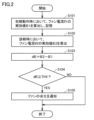
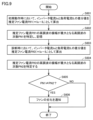
- FIG. 5 is a flow chart showing a procedure for diagnosing deterioration of cooling fan 51 in the first embodiment.
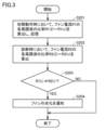
- FIG. 10 is a flow chart showing a procedure for diagnosing deterioration of cooling fan 51 in Embodiment 2.
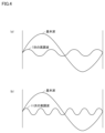
- FIG. (a) is a diagram showing the fundamental wave of the fan current If1 at the time of initial operation and the harmonic wave with the maximum amplitude.
- (b) is a diagram showing the fundamental wave of the fan current If2 at the time of diagnosis and the harmonic wave with the maximum amplitude.
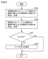
- 11 is a flow chart showing a procedure for diagnosing deterioration of cooling fan 51 according to the third embodiment.
- FIG. 11 is a circuit block diagram showing the configuration of an uninterruptible power supply 1 according to Embodiment 4;
- FIG. 11 is a flow chart showing a procedure for diagnosing deterioration of cooling fan 51 in Embodiment 4.
- FIG. 19 is a flow chart showing a procedure for diagnosing deterioration of cooling fan 51 according to Embodiment 5.
- FIG. 12 is a flow chart showing a procedure for diagnosing deterioration of cooling fan 51 in Embodiment 6.
- FIG. 1 is a circuit block diagram showing the configuration of an uninterruptible power supply 1 according to Embodiment 1.
- the uninterruptible power supply 1 once converts three-phase AC power supplied from a commercial AC power supply 21 into DC power, converts the DC power into three-phase AC power, and supplies the load 24 with the three-phase AC power.
- U phase, V phase, W phase for example, U phase
- this uninterruptible power supply 1 includes an AC input terminal T1, a bypass input terminal T2, a battery terminal T3, and an AC output terminal T4.
- AC input terminal T ⁇ b>1 receives AC power of commercial frequency from commercial AC power supply 21 .
- a bypass input terminal T2 receives commercial-frequency AC power from a bypass AC power supply 22 .
- the bypass AC power supply 22 may be a commercial AC power supply or a generator.
- the battery terminal T3 is connected to a battery (power storage device) 23.
- Battery 23 stores DC power.
- a capacitor may be connected instead of the battery 23 .
- the AC output terminal T4 is connected to the load 24.
- the load 24 is driven by AC power.
- the uninterruptible power supply 1 further includes magnetic contactors 2, 8, 14, 17, current detectors 3, 11, 15, capacitors 4, 9, 13, reactors 5, 12, a converter 6, a bidirectional chopper 7, an inverter 10 , a semiconductor switch 16 , an operation unit 18 and a control device 19 .
- the first terminal of the electromagnetic contactor 2 is connected to the AC input terminal T1, and the second terminal (node ND1) of the electromagnetic contactor 2 is connected to the first terminal of the reactor 5.
- a second terminal of reactor 5 is connected to AC terminal 6 a of converter 6 .
- Capacitor 4 is connected between node ND1 and neutral point NP.
- Neutral point NP receives, for example, a ground voltage.
- the electromagnetic contactor 2 is turned on when the uninterruptible power supply 1 is used, and turned off during maintenance of the uninterruptible power supply 1, for example.
- the instantaneous value of the AC input voltage Vi appearing at the node ND1 is detected by the control device 19. Based on the instantaneous value of the AC input voltage Vi, it is determined whether or not a power failure has occurred.
- Current detector 3 detects AC input current Ii flowing to node ND1 and provides control device 19 with a signal indicating the detected value.
- the capacitor 4 and the reactor 5 constitute an AC filter F1, which allows AC power of commercial frequency to pass through and prevents switching frequency current generated in the converter 6 from passing to the commercial AC power supply 21.
- the converter 6 is controlled by the control device 19, and when AC power is normally supplied from the commercial AC power supply 21 (when the commercial AC power supply 21 is healthy), the AC power is converted into DC power and supplied to the DC line L1. output to When AC power is no longer supplied normally from commercial AC power supply 21 (at the time of power failure of commercial AC power supply 21), operation of converter 6 is stopped. The output voltage of converter 6 can be controlled to a desired value.
- the capacitor 9 is connected to the DC line L1 and smoothes the voltage of the DC line L1.
- the instantaneous value of the DC voltage VDC appearing on the DC line L1 is detected by the controller 19 .
- the DC line L1 is connected to the high voltage side node of the bidirectional chopper 7, and the low voltage side node of the bidirectional chopper 7 is connected via the electromagnetic contactor 8 to the battery terminal T3.
- the electromagnetic contactor 8 is turned on when the uninterruptible power supply 1 is used, and turned off during maintenance of the uninterruptible power supply 1 and the battery 23, for example.
- the instantaneous value of the terminal voltage VB of battery 23 appearing at battery terminal T3 is detected by control device 19 .
- the bidirectional chopper 7 is controlled by the control device 19, stores the DC power generated by the converter 6 in the battery 23 when the commercial AC power supply 21 is healthy, and converts the DC power of the battery 23 into a DC power supply when the commercial AC power supply 21 fails. It is supplied to inverter 10 via line L1.
- the bi-directional chopper 7 steps down the DC voltage VDC of the DC line L ⁇ b>1 and supplies it to the battery 23 .
- bidirectional chopper 7 boosts voltage VB across terminals of battery 23 and outputs the boosted voltage to DC line L1.
- DC line L ⁇ b>1 is connected to an input node of inverter 10 .
- the inverter 10 is controlled by the control device 19, converts the DC power supplied from the converter 6 or the bidirectional chopper 7 through the DC line L1 into AC power of commercial frequency, and outputs the AC power. That is, the inverter 10 converts the DC power supplied from the converter 6 via the DC line L1 into AC power when the commercial AC power supply 21 is normal, and converts the DC power from the battery 23 to the bidirectional chopper 7 when the commercial AC power supply 21 is out of power. converts the DC power supplied through the to AC power.
- the output voltage of inverter 10 can be controlled to a desired value.
- the AC terminal 10a of the inverter 10 is connected to the first terminal of the reactor 12, the second terminal (node ND2) of the reactor 12 is connected to the first terminal of the magnetic contactor 14, and the second terminal of the magnetic contactor 14 is connected. (node ND3) is connected to AC output terminal T4.
- Capacitor 13 is connected between node ND2 and neutral point NP.
- Neutral point NP receives, for example, a ground voltage.
- the current detector 11 detects the instantaneous value of the output current (AC output current, inverter current) Io of the inverter 10 and gives the controller 19 a signal indicating the detected value.
- the instantaneous value of AC output voltage Vo appearing at node ND2 is detected by controller 19 .
- the reactor 12 and the capacitor 13 constitute an AC filter F2, pass the AC power of the commercial frequency generated by the inverter 10 to the AC output terminal T4, and pass the current of the switching frequency generated by the inverter 10 to the AC output terminal T4. to prevent
- the electromagnetic contactor 14 is controlled by the control device 19, is turned on in the inverter power supply mode in which the AC power generated by the inverter 10 is supplied to the load 24, and is bypass power supply in which the AC power from the bypass AC power supply 22 is supplied to the load 24. turned off in mode.
- Current detector 15 detects an instantaneous value of load current IL flowing between node ND3 and AC output terminal T4, and provides controller 19 with a signal indicating the detected value.
- the semiconductor switch 16 includes a pair of thyristors connected in antiparallel to each other, and is connected between the bypass input terminal T2 and the node ND3.
- the electromagnetic contactor 17 is connected in parallel with the semiconductor switch 16 .
- the semiconductor switch 16 is controlled by the control device 19 and is normally turned off. When the inverter 10 fails, the semiconductor switch 16 is turned on instantaneously to supply AC power from the bypass AC power supply 22 to the load 24 . The semiconductor switch 16 is turned off after a predetermined time has passed since it was turned on.
- the electromagnetic contactor 17 is turned off in the inverter power supply mode in which the AC power generated by the inverter 10 is supplied to the load 24, and is turned on in the bypass power supply mode in which the AC power from the bypass AC power supply 22 is supplied to the load 24.
- the electromagnetic contactor 17 is turned on when the inverter 10 fails, and supplies AC power from the bypass AC power supply 22 to the load 24 . That is, when the inverter 10 fails, the semiconductor switch 16 is instantaneously turned on for a predetermined time and the electromagnetic contactor 17 is turned on. This is to prevent the semiconductor switch 16 from being overheated and damaged.
- the operation unit 18 includes a plurality of buttons operated by the user of the uninterruptible power supply 1. By operating the operation unit 18, the user can turn on and off the power of the uninterruptible power supply 1, or select one of the bypass power supply mode and the inverter power supply mode. Become.
- the control device 19 receives a signal from the operation unit 18, an AC input voltage Vi, an AC input current Ii, a DC voltage VDC, a voltage VB between terminals of the battery 23, an output current Io of the inverter 10, an AC output voltage Vo, and a load current IL and the like to control the entire uninterruptible power supply 1 . That is, control device 19 detects whether or not a power failure has occurred based on the detected value of AC input voltage Vi, and controls converter 6 and inverter 10 in synchronization with the phase of AC input voltage Vi.
- the control device 19 controls the converter 6 based on the AC input voltage Vi, the AC input current Ii, and the DC voltage VDC.
- the controller 19 controls the converter 6 so that the DC voltage VDC becomes a desired target voltage VDCT when the commercial AC power supply 21 is healthy, and stops the operation of the converter 6 when the commercial AC power supply 21 fails.
- the control device 19 controls the bidirectional chopper 7 based on the DC voltage VDC and the voltage VB across the terminals of the battery 23 .
- the control device 19 controls the bidirectional chopper 7 so that the voltage VB across the terminals of the battery 23 becomes a desired target voltage VBT across the terminals when the commercial AC power supply 21 is healthy, and when the commercial AC power supply 21 fails, the DC voltage
- the bi-directional chopper 7 is controlled so that VDC becomes the desired target voltage VDCT.
- the control device 19 controls the inverter 10 based on the AC output current Io and the AC output voltage Vo so that the AC output voltage Vo becomes the desired target voltage VoT. Controller 19 constantly monitors load current IL, and protects uninterruptible power supply 1 by turning off magnetic contactors 14 and 17 and semiconductor switch 16, for example, when load current IL becomes excessive.
- the uninterruptible power supply 1 further includes a cooling fan 51, an electromagnetic contactor 20, a current detector 52, and a display device 53.
- a first terminal of the electromagnetic contactor 20 is connected to the node ND3, and a second terminal of the electromagnetic contactor 20 is connected to the cooling fan 51.
- the cooling fan 51 receives AC power supplied from the inverter 10 when the electromagnetic contactor 20 is turned on.
- the cooling fan 51 operates using this AC power to lower the temperature inside the housing in which the uninterruptible power supply 1 is accommodated.
- the current detector 52 detects the instantaneous value of the current (hereinafter referred to as "fan current”) If flowing through the cooling fan 51 and provides the controller 19 with a signal indicating the detected value.
- a constant voltage is always input to the cooling fan 51, and it always rotates at the rated speed. Therefore, as the cooling fan 51 deteriorates, the fan current If increases in order to maintain the rotation speed of the cooling fan 51 .
- the control device 19 diagnoses deterioration of the cooling fan 51 by monitoring the fan current If1 during initial operation of the uninterruptible power supply 1 and the fan current If2 during diagnosis. It is assumed that the cooling fan 51 has not deteriorated during the initial operation of the uninterruptible power supply 1 .
- control device 19 calculates effective value IE1 of fan current If1 detected by current detector 52 during initial operation from effective value IE2 of fan current If2 detected by current detector 52 during diagnosis.
- IE1 of fan current If1 detected by current detector 52 is calculated from effective value IE2 of fan current If2 detected by current detector 52 during diagnosis.
- FIG. 2 is a flow chart showing a procedure for diagnosing deterioration of cooling fan 51 according to the first embodiment.
- control device 19 receives a signal representing the magnitude of current (fan current) If1 flowing through cooling fan 51 output from current detector 52, and detects fan current If1 at the time of initial operation. is calculated and stored.
- control device 19 receives a signal representing the magnitude of current (fan current) If2 flowing in cooling fan 51 output from current detector 52, and determines the effectiveness of fan current If2 at the time of diagnosis. Calculate the value IE2.
- step S103 the control device 19 subtracts the effective value IE1 of the fan current If1 during initial operation from the effective value IE2 of the fan current If2 during diagnosis to calculate a difference value dIE.
- step S104 when the difference value dIE is equal to or greater than the threshold THX, the process proceeds to step S105.
- step S105 the control device 19 notifies the user of the uninterruptible power supply 1 through the display device 53 that the cooling fan 51 has deteriorated.
- deterioration of the cooling fan can be easily diagnosed by monitoring the current flowing through the cooling fan.
- FIG. 3 is a flow chart showing the procedure for diagnosing deterioration of the cooling fan 51 according to the second embodiment.
- control device 19 receives a signal representing the magnitude of current (fan current) If1 flowing through cooling fan 51 output from current detector 52, and receives fan current If1 at the time of initial operation.
- the ratios R1(2) to R1(n) of the 2nd to nth order harmonics of are calculated and stored.
- control device 19 receives a signal representing the magnitude of current (fan current) If2 flowing in cooling fan 51 output from current detector 52, and determines whether fan current If2 at the time of diagnosis is 2 Calculate the ratios R2(2) to R2(n) of the harmonics of order n.
- step S203 when the ratio R1(i) of the i-th harmonic of the fan current If1 during the initial operation is different from the ratio R2(i) of the i-th harmonic of the fan current If2 during the diagnosis, the process goes to step S204.
- i any of 2 to n.
- step S204 the control device 19 notifies the user of the uninterruptible power supply 1 through the display device 53 that the cooling fan 51 has deteriorated.
- control device 19 determines, at the time of diagnosis, the order N2 of the harmonic having the maximum amplitude of the fan current If2 detected by the current detector 52 and When the amplitude of the fan current If1 is different from the maximum harmonic order N1, it is diagnosed that the cooling fan 51 is deteriorated.
- FIG. 4(a) is a diagram showing the fundamental wave of the fan current If1 during the initial operation and the harmonic wave with the maximum amplitude.
- FIG. 4(b) is a diagram showing the fundamental wave of the fan current If2 at the time of diagnosis and the harmonic wave with the maximum amplitude.
- the order of the harmonic with the maximum amplitude of the fan current If1 at the time of initial operation is "7".
- the order of the harmonic with the maximum amplitude of the fan current If2 at the time of diagnosis is "11".
- FIG. 5 is a flow chart showing the procedure for diagnosing deterioration of the cooling fan 51 according to the third embodiment.
- control device 19 receives a signal representing the magnitude of current (fan current) If1 flowing through cooling fan 51 output from current detector 52, and receives fan current If1 at the time of initial operation. is obtained and stored.
- control device 19 receives a signal representing the magnitude of current (fan current) If2 flowing through cooling fan 51 output from current detector 52, and determines the amplitude of fan current If2 at the time of diagnosis. is the maximum harmonic order N2.
- step S503 when the order N2 of the harmonic with the maximum amplitude of the fan current If2 at the time of diagnosis is different from the order N1 of the harmonic with the maximum amplitude of the fan current If1 during the initial operation, the control device 19 , the process proceeds to step S504.
- step S504 the control device 19 notifies the user of the uninterruptible power supply 1 through the display device 53 that the cooling fan 51 has deteriorated.
- FIG. 6 is a circuit block diagram showing the configuration of an uninterruptible power supply 1 according to Embodiment 4. As shown in FIG.
- the uninterruptible power supply 1 of Embodiment 4 differs from the uninterruptible power supply 1 of Embodiments 1 to 3 in that the uninterruptible power supply 1 of Embodiment 4 does not include the current detector 52. is. Thereby, in Embodiment 4, the structure of the uninterruptible power supply 1 can be simplified.
- control device 19 estimates the result of subtracting the load current IL detected by the current detector 15 from the inverter current Io detected by the current detector 11 as the fan current during initial operation. At the time of diagnosis, control device 19 estimates the result of subtracting load current IL detected by current detector 15 from inverter current Io detected by current detector 11 as the fan current at the time of diagnosis.
- the control device 19 When the result dPIE obtained by subtracting the estimated effective value PIE1 of the fan current PIf1 at the time of initial operation from the estimated effective value PIE2 of the fan current PIf2 at the time of diagnosis, the control device 19 operates the cooling fan 51 is diagnosed as deteriorating.
- FIG. 7 is a flowchart showing the procedure for diagnosing deterioration of the cooling fan 51 according to the fourth embodiment.
- step S302 the control device 19 calculates and stores the effective value PIE1 of the estimated fan current PIf1 during the initial operation.
- step S304 the control device 19 calculates the effective value PIE2 of the estimated fan current PIf2 at the time of diagnosis.
- step S305 the control device 19 subtracts the effective value PIE1 of the estimated fan current during the initial operation from the effective value PIE2 of the estimated fan current during diagnosis to calculate the difference value dPIE.
- step S306 when the difference value dPIE is equal to or greater than the threshold THZ, the process proceeds to step S307.
- step S307 the control device 19 notifies the user of the uninterruptible power supply 1 through the display device 53 that the cooling fan 51 has deteriorated.
- deterioration of the cooling fan can be easily diagnosed without providing a sensor for detecting the current flowing through the cooling fan.
- control device 19 estimates the result of subtracting the load current IL detected by the current detector 15 from the inverter current Io detected by the current detector 11 as the fan current during initial operation. At the time of diagnosis, control device 19 estimates the result of subtracting load current IL detected by current detector 15 from inverter current Io detected by current detector 11 as the fan current at the time of diagnosis.
- the control device 19 sets a ratio PR2(i) of the i-th order harmonic component of the fan current PIf2 estimated at the time of diagnosis and a ratio PR1(i) of the i-th order harmonic component of the fan current PIf1 estimated at the time of initial operation.
- (i) is different, it is diagnosed that the cooling fan 51 is deteriorated.
- i 2 to n.
- n is the highest order of the harmonic component of the fan current.
- FIG. 8 is a flow chart showing the procedure for diagnosing deterioration of the cooling fan according to the fifth embodiment.
- step S402 the control device 19 calculates and stores the ratios PR1(2) to PR1(n) of the 2nd to nth order harmonics of the estimated fan current PIf1 during the initial operation.
- step S404 the control device 19 calculates the ratios PR2(2) to PR2(n) of the 2nd to n-order harmonics of the estimated fan current PIf2 at the time of diagnosis.
- step S405 when the ratio PR1(i) of the i-th harmonic of the estimated fan current PIf1 at the time of initial operation differs from the ratio PR2(i) of the i-th harmonic of the estimated fan current PIf2 at the time of diagnosis , the process proceeds to step S406.
- i any of 2 to n.
- step S406 the control device 19 notifies the user of the uninterruptible power supply 1 through the display device 53 that the cooling fan 51 has deteriorated.
- control device 19 estimates the result of subtracting the load current IL detected by the current detector 15 from the inverter current Io detected by the current detector 11 as the fan current during initial operation. At the time of diagnosis, control device 19 estimates the result of subtracting load current IL detected by current detector 15 from inverter current Io detected by current detector 11 as the fan current at the time of diagnosis.
- the control device 19 determines that the estimated harmonic order PN2 of the maximum amplitude of the fan current PIf2 at the time of diagnosis and the estimated harmonic order PN1 of the maximum amplitude of the fan current PIf1 during the initial operation are different. Sometimes, it is diagnosed that the cooling fan 51 is deteriorated.
- FIG. 9 is a flow chart showing the procedure for diagnosing deterioration of the cooling fan according to the sixth embodiment.
- step S602 the control device 19 identifies and stores the order PN1 of the harmonics having the maximum amplitude of the estimated fan current PIf1 during the initial operation.
- step S604 the control device 19 identifies the order PN2 of the harmonic with the maximum amplitude of the estimated fan current PIf2 at the time of diagnosis.
- step S605 when the order PN2 of the harmonic with the maximum amplitude of the estimated fan current PIf2 at the time of diagnosis is different from the order PN1 of the harmonic with the maximum amplitude of the estimated fan current PIf1 at the time of initial operation, the process is executed. Proceed to S606.
- step S606 the control device 19 notifies the user of the uninterruptible power supply 1 through the display device 53 that the cooling fan 51 has deteriorated.
- the control device may calculate the effective value of the fan current, the ratio of harmonics, and the order of the highest amplitude harmonic a plurality of times during the initial operation, and use the average value thereof.
- Degree of deterioration The controller determines the magnitude of the difference between dIE and THX, the magnitude of the difference between dPIE and THZ, the magnitude of the difference between R1(i) and R2(i), PR1 (i) the magnitude of the difference between PR2(i), the number of i that R1(i) differs from R2(i), the number of i that PR1(i) differs from PR2(i) , the difference between N1 and N2, and the difference between PN1 and PN2, the greater the degree of deterioration of the cooling fan 51 may be determined.
- Combination of Embodiments Embodiments 1 to 6 may be used in combination.
- the control device may notify the deterioration of the fan.
- the control device may notify deterioration of the fan.
Landscapes
- Business, Economics & Management (AREA)
- Emergency Management (AREA)
- Engineering & Computer Science (AREA)
- Power Engineering (AREA)
- Stand-By Power Supply Arrangements (AREA)
- Inverter Devices (AREA)
Abstract
筐体内に設けられた無停電電源装置は、商用交流電源(21)からの第1の交流電力を直流電力に変換するコンバータ(6)と、コンバータ(6)によって生成された直流電力または電力貯蔵装置(23)から供給される直流電力を第2の交流電力に変換して負荷(24)に供給するインバータ(10)と、常時定格回転数で回転して、筐体内の温度を下げるための冷却ファン(51)と、無停電電源装置の初期動作時の冷却ファン(51)に流れるファン電流と、診断時の冷却ファン(51)に流れる電流とに基づいて、冷却ファン(51)の劣化を診断する制御装置(19)とを備える。
Description
本開示は、無停電電源装置に関する。
従来から、コンピュータシステムなど重要な負荷に対して電力を安定的に供給するために無停電電源が用いられている。無停電電源装置は、一般的に、商用交流電力を直流電力に変換するコンバータと、バッテリなどの電力貯蔵装置と、コンバータから生成した直流電力あるいは電力貯蔵装置からの直流電力を交流電力に変換して負荷に供給するインバータとを備える。無停電電源装置が電力貯蔵装置の直流電力を変換するチョッパをさらに備えていることもある。無停電電源装置は、無停電電源装置の本体部が収納された筐体内を冷却するための冷却ファンを備える。
冷却ファンの劣化を診断する機能を有する無停電電源装置が知られている。たとえば、特許文献1には、FANに流れる電流を電圧信号に変換して出力するFAN電流検出部、FAN電流検出部が検出した電圧信号波形をFAN回転数の検出に適した信号波形に変換する波形成形部、および波形成形部から出力される信号波形に基づいてFANの動作状態を診断するFAN状態診断部を備える。
しかしながら、特許文献1に記載の無停電電源装置は、劣化に応じて回転数が変化する冷却ファンを診断の対象としており、常時定格回転数で回転する冷却ファンの劣化を診断することができない。
それゆえに、本開示の目的は、常時定格回転数で回転する冷却ファンの劣化を診断することができる無停電電源装置を提供することである。
本開示の筐体内に設けられた無停電電源装置は、商用交流電源からの第1の交流電力を直流電力に変換するコンバータと、コンバータによって生成された直流電力または電力貯蔵装置から供給される直流電力を第2の交流電力に変換して負荷に供給するインバータと、常時定格回転数で回転して、筐体内の温度を下げるための冷却ファンと、無停電電源装置の初期動作時の冷却ファンに流れるファン電流と、診断時の冷却ファンに流れる電流とに基づいて、冷却ファンの劣化を診断する制御装置とを備える。
本開示の無停電電源装置によれば、常時定格回転数で回転する冷却ファンの劣化を診断することができる。
以下、実施の形態について図面を参照して説明する。
[実施の形態1]
図1は、実施の形態1による無停電電源装置1の構成を示す回路ブロック図である。無停電電源装置1は、商用交流電源21から供給される三相交流電力を直流電力に一旦変換し、その直流電力を三相交流電力に変換して負荷24に供給するものである。図1では、図面および説明の簡単化のため、三相(U相、V相、W相)のうちの一相(たとえばU相)に対応する部分の回路のみが示されている。
[実施の形態1]
図1は、実施の形態1による無停電電源装置1の構成を示す回路ブロック図である。無停電電源装置1は、商用交流電源21から供給される三相交流電力を直流電力に一旦変換し、その直流電力を三相交流電力に変換して負荷24に供給するものである。図1では、図面および説明の簡単化のため、三相(U相、V相、W相)のうちの一相(たとえばU相)に対応する部分の回路のみが示されている。
図1において、この無停電電源装置1は、交流入力端子T1、バイパス入力端子T2、バッテリ端子T3、および交流出力端子T4を備える。
交流入力端子T1は、商用交流電源21から商用周波数の交流電力を受ける。
バイパス入力端子T2は、バイパス交流電源22から商用周波数の交流電力を受ける。バイパス交流電源22は、商用交流電源であってもよいし、発電機であっても構わない。
バイパス入力端子T2は、バイパス交流電源22から商用周波数の交流電力を受ける。バイパス交流電源22は、商用交流電源であってもよいし、発電機であっても構わない。
バッテリ端子T3は、バッテリ(電力貯蔵装置)23に接続される。バッテリ23は、直流電力を蓄える。バッテリ23の代わりにコンデンサが接続されていても構わない。
交流出力端子T4は、負荷24に接続される。負荷24は、交流電力によって駆動される。
無停電電源装置1は、さらに、電磁接触器2,8,14,17、電流検出器3,11,15、コンデンサ4,9,13、リアクトル5,12、コンバータ6、双方向チョッパ7、インバータ10、半導体スイッチ16、操作部18、および制御装置19を備える。
電磁接触器2の第1端子は交流入力端子T1に接続され、電磁接触器2の第2端子(ノードND1)はリアクトル5の第1端子に接続される。リアクトル5の第2端子はコンバータ6の交流端子6aに接続される。コンデンサ4は、ノードND1と中性点NPとの間に接続される。中性点NPは、たとえば接地電圧を受ける。電磁接触器2は、無停電電源装置1の使用時にオンされ、たとえば無停電電源装置1のメンテナンス時にオフされる。
ノードND1に現れる交流入力電圧Viの瞬時値は、制御装置19によって検出される。交流入力電圧Viの瞬時値に基づいて、停電の発生の有無などが判別される。電流検出器3は、ノードND1に流れる交流入力電流Iiを検出し、その検出値を示す信号を制御装置19に与える。
コンデンサ4およびリアクトル5は、交流フィルタF1を構成し、商用周波数の交流電力を通過させるとともに、コンバータ6で発生するスイッチング周波数の電流が商用交流電源21に通過することを防止する。
コンバータ6は、制御装置19によって制御され、商用交流電源21から交流電力が正常に供給されている場合(商用交流電源21の健全時)には、交流電力を直流電力に変換して直流ラインL1に出力する。商用交流電源21から交流電力が正常に供給されなくなった場合(商用交流電源21の停電時)には、コンバータ6の運転は停止される。コンバータ6の出力電圧は、所望の値に制御可能になっている。
コンデンサ9は、直流ラインL1に接続され、直流ラインL1の電圧を平滑化させる。直流ラインL1に現れる直流電圧VDCの瞬時値は、制御装置19によって検出される。直流ラインL1は双方向チョッパ7の高電圧側ノードに接続され、双方向チョッパ7の低電圧側ノードは電磁接触器8を介してバッテリ端子T3に接続される。
電磁接触器8は、無停電電源装置1の使用時はオンされ、たとえば無停電電源装置1およびバッテリ23のメンテナンス時にオフされる。バッテリ端子T3に現れるバッテリ23の端子間電圧VBの瞬時値は、制御装置19によって検出される。
双方向チョッパ7は、制御装置19によって制御され、商用交流電源21の健全時には、コンバータ6によって生成された直流電力をバッテリ23に蓄え、商用交流電源21の停電時には、バッテリ23の直流電力を直流ラインL1を介してインバータ10に供給する。
双方向チョッパ7は、直流電力をバッテリ23に蓄える場合には、直流ラインL1の直流電圧VDCを降圧してバッテリ23に与える。双方向チョッパ7は、バッテリ23の直流電力をインバータ10に供給する場合には、バッテリ23の端子間電圧VBを昇圧して直流ラインL1に出力する。直流ラインL1は、インバータ10の入力ノードに接続されている。
インバータ10は、制御装置19によって制御され、コンバータ6または双方向チョッパ7から直流ラインL1を介して供給される直流電力を商用周波数の交流電力に変換して出力する。すなわち、インバータ10は、商用交流電源21の健全時には、コンバータ6から直流ラインL1を介して供給される直流電力を交流電力に変換し、商用交流電源21の停電時には、バッテリ23から双方向チョッパ7を介して供給される直流電力を交流電力に変換する。インバータ10の出力電圧は、所望の値に制御可能になっている。
インバータ10の交流端子10aは、リアクトル12の第1端子に接続され、リアクトル12の第2端子(ノードND2)は、電磁接触器14の第1端子に接続され、電磁接触器14の第2端子(ノードND3)は交流出力端子T4に接続される。コンデンサ13は、ノードND2と中性点NPとの間に接続される。中性点NPは、たとえば接地電圧を受ける。
電流検出器11は、インバータ10の出力電流(交流出力電流、インバータ電流)Ioの瞬時値を検出し、その検出値を示す信号を制御装置19に与える。ノードND2に現れる交流出力電圧Voの瞬時値は、制御装置19によって検出される。
リアクトル12およびコンデンサ13は、交流フィルタF2を構成し、インバータ10で生成される商用周波数の交流電力を交流出力端子T4に通過させ、インバータ10で発生するスイッチング周波数の電流が交流出力端子T4に通過することを防止する。
電磁接触器14は、制御装置19によって制御され、インバータ10によって生成された交流電力を負荷24に供給するインバータ給電モード時にはオンされ、バイパス交流電源22からの交流電力を負荷24に供給するバイパス給電モード時にはオフされる。電流検出器15は、ノードND3と交流出力端子T4との間に流れる負荷電流ILの瞬時値を検出し、その検出値を示す信号を制御装置19に与える。
半導体スイッチ16は、互いに逆並列に接続された一対のサイリスタを含み、バイパス入力端子T2とノードND3との間に接続される。電磁接触器17は、半導体スイッチ16に並列接続される。半導体スイッチ16は、制御装置19によって制御され、通常はオフされ、インバータ10が故障した場合には瞬時にオンし、バイパス交流電源22からの交流電力を負荷24に供給する。半導体スイッチ16は、オンしてから所定時間経過後にオフする。
電磁接触器17は、インバータ10によって生成された交流電力を負荷24に供給するインバータ給電モード時にはオフされ、バイパス交流電源22からの交流電力を負荷24に供給するバイパス給電モード時にはオンされる。
電磁接触器17は、インバータ10が故障した場合にオンし、バイパス交流電源22からの交流電力を負荷24に供給する。つまり、インバータ10が故障した場合には、半導体スイッチ16が瞬時に所定時間だけオンするとともに電磁接触器17がオンする。これは、半導体スイッチ16が過熱されて破損するのを防止するためである。
操作部18は、無停電電源装置1の使用者によって操作される複数のボタンを含む。使用者が操作部18を操作することにより、無停電電源装置1の電源をオンおよびオフしたり、バイパス給電モードおよびインバータ給電モードのうちのいずれか一方のモードを選択したりすることが可能となる。
制御装置19は、操作部18からの信号、交流入力電圧Vi、交流入力電流Ii、直流電圧VDC、バッテリ23の端子間電圧VB、インバータ10の出力電流Io、交流出力電圧Vo、および負荷電流ILなどに基づいて無停電電源装置1全体を制御する。すなわち、制御装置19は、交流入力電圧Viの検出値に基づいて停電が発生したか否かを検出し、交流入力電圧Viの位相に同期してコンバータ6およびインバータ10を制御する。
制御装置19は、交流入力電圧Vi、交流入力電流Ii、および直流電圧VDCに基づいてコンバータ6を制御する。制御装置19は、商用交流電源21の健全時には、直流電圧VDCが所望の目標電圧VDCTになるようにコンバータ6を制御し、商用交流電源21の停電時には、コンバータ6の運転を停止させる。
制御装置19は、直流電圧VDCおよびバッテリ23の端子間電圧VBに基づいて双方向チョッパ7を制御する。制御装置19は、商用交流電源21の健全時には、バッテリ23の端子間電圧VBが所望の目標端子間電圧VBTになるように双方向チョッパ7を制御し、商用交流電源21の停電時には、直流電圧VDCが所望の目標電圧VDCTになるように双方向チョッパ7を制御する。
制御装置19は、交流出力電流Ioおよび交流出力電圧Voに基づいて、交流出力電圧Voが所望の目標電圧VoTになるようにインバータ10を制御する。制御装置19は、負荷電流ILを常時監視し、たとえば負荷電流ILが過大になった場合には電磁接触器14,17および半導体スイッチ16をオフさせて無停電電源装置1を保護する。
無停電電源装置1は、さらに、冷却ファン51と、電磁接触器20と、電流検出器52と、表示装置53を備える。
電磁接触器20の第1端子はノードND3に接続され、電磁接触器20の第2端子は、冷却ファン51に接続される。
冷却ファン51は、電磁接触器20がオンすることにより、インバータ10から供給される交流電力を受ける。冷却ファン51は、この交流電力を用いて動作して、無停電電源装置1が収容される筐体の内部の温度を下げる。
電流検出器52は、冷却ファン51に流れる電流(以下、ファン電流)Ifの瞬時値を検出し、その検出値を示す信号を制御装置19に与える。
冷却ファン51には、常時一定電圧が入力され、常時定格回転数で回転する。そのため、冷却ファン51の劣化が進むと、冷却ファン51の回転数を維持するため、ファン電流Ifが増加する。
制御装置19は、無停電電源装置1の初期動作時のファン電流If1と、診断時のファン電流If2とを監視することによって、冷却ファン51の劣化を診断する。無停電電源装置1の初期動作時において、冷却ファン51は劣化していないことを前提としている。
本実施の形態では、制御装置19は、診断時において電流検出器52によって検出されたファン電流If2の実効値IE2から初期動作時において電流検出器52によって検出されたファン電流If1の実効値IE1を減算した結果dIEが、閾値以上のときに、冷却ファン51が劣化していると診断する。
表示装置53は、冷却ファン51の劣化の有無などを通知する。
図2は、実施の形態1における冷却ファン51の劣化診断の手順を表わすフローチャートである。
図2は、実施の形態1における冷却ファン51の劣化診断の手順を表わすフローチャートである。
ステップS101において、初期動作時において、制御装置19は、電流検出器52から出力される冷却ファン51に流れる電流(ファン電流)If1の大きさを表わす信号を受けて、初期動作時のファン電流If1の実効値IE1を算出し、記憶する。
ステップS102において、診断時において、制御装置19は、電流検出器52から出力される冷却ファン51に流れる電流(ファン電流)If2の大きさを表わす信号を受けて、診断時のファン電流If2の実効値IE2を算出する。
ステップS103において、制御装置19は、診断時のファン電流If2の実効値IE2から初期動作時のファン電流If1の実効値IE1を減算して、差分値dIEを算出する。
ステップS104において、差分値dIEが閾値THX以上のときには、処理がステップS105に進む。
ステップS105において、制御装置19は、冷却ファン51の劣化したことを表示装置53を通じて無停電電源装置1の使用者に通知する。
以上のように、本実施の形態によれば、冷却ファンに流れる電流を監視することによって、冷却ファンの劣化を簡易に診断することができる。
[実施の形態2]
実施の形態2の無停電電源装置1の構成は、実施の形態1の無停電電源装置1の構成と同様である。
実施の形態2の無停電電源装置1の構成は、実施の形態1の無停電電源装置1の構成と同様である。
本実施の形態では、制御装置19は、診断時において、電流検出器52によって検出されたファン電流If2のi次の高調波成分の比率R2(i)と、初期動作時において電流検出器52によって検出されたファン電流If1のi次の高調波成分の比率R1(i)とが相違するときに、冷却ファン51が劣化していると診断する。i=2~nのいずれかである。nはファン電流の高調波成分の最大の次数である。たとえば、初期動作時の7次の高調波の比率R1(7)が20%であるのに対して、診断時の7次の高調波の比率R2(7)が30%のときに、冷却ファン51が劣化していると診断される。
図3は、実施の形態2における冷却ファン51の劣化診断の手順を表わすフローチャートである。
ステップS201において、初期動作時において、制御装置19は、電流検出器52から出力される冷却ファン51に流れる電流(ファン電流)If1の大きさを表わす信号を受けて、初期動作時のファン電流If1の2~n次の高調波の比率R1(2)~R1(n)を算出して、記憶する。
ステップS202において、診断時において、制御装置19は、電流検出器52から出力される冷却ファン51に流れる電流(ファン電流)If2の大きさを表わす信号を受けて、診断時のファン電流If2の2~n次の高調波の比率R2(2)~R2(n)を算出する。
ステップS203において、初期動作時のファン電流If1のi次の高調波の比率R1(i)と診断時のファン電流If2のi次の高調波の比率R2(i)とが相違するときに、処理がステップS204に進む。ここで、i=2~nのいずれかである。
ステップS204において、制御装置19は、冷却ファン51の劣化したことを表示装置53を通じて無停電電源装置1の使用者に通知する。
[実施の形態3]
実施の形態3の無停電電源装置1の構成は、実施の形態1の無停電電源装置1の構成と同様である。
実施の形態3の無停電電源装置1の構成は、実施の形態1の無停電電源装置1の構成と同様である。
本実施の形態では、制御装置19は、診断時において、電流検出器52によって検出されたファン電流If2の振幅が最大の高調波の次数N2と、初期動作時において電流検出器52によって検出されたファン電流If1の振幅が最大の高調波の次数N1とが相違するときに、冷却ファン51が劣化していると診断する。
図4(a)は、初期動作時のファン電流If1の基本波、および振幅が最大の高調波を表わす図である。図4(b)は、診断時のファン電流If2の基本波、および振幅が最大の高調波を表わす図である。図4(a)に示すように、初期動作時においてファン電流If1の振幅が最大の高調波の次数は「7」である。図4(b)に示すように、診断時においてファン電流If2の振幅が最大の高調波の次数は「11」である。
図5は、実施の形態3における冷却ファン51の劣化診断の手順を表わすフローチャートである。
ステップS501において、初期動作時において、制御装置19は、電流検出器52から出力される冷却ファン51に流れる電流(ファン電流)If1の大きさを表わす信号を受けて、初期動作時のファン電流If1の振幅が最大の高調波の次数N1を求めて、記憶する。
ステップS502において、診断時において、制御装置19は、電流検出器52から出力される冷却ファン51に流れる電流(ファン電流)If2の大きさを表わす信号を受けて、診断時のファン電流If2の振幅が最大の高調波の次数N2を求める。
ステップS503において、制御装置19は、診断時のファン電流If2の振幅が最大の高調波の次数N2と、初期動作時のファン電流If1の振幅が最大の高調波の次数N1とが相違するときに、処理がステップS504に進む。
ステップS504において、制御装置19は、冷却ファン51の劣化したことを表示装置53を通じて無停電電源装置1の使用者に通知する。
[実施の形態4]
図6は、実施の形態4による無停電電源装置1の構成を示す回路ブロック図である。
図6は、実施の形態4による無停電電源装置1の構成を示す回路ブロック図である。
実施の形態4の無停電電源装置1は、実施の形態1~3の無停電電源装置1と相違する点は、実施の形態4の無停電電源装置1は、電流検出器52を備えない点である。これにより、実施の形態4では、無停電電源装置1の構成を簡易化できる。
制御装置19は、初期動作時において、電流検出器11によって検出されたインバータ電流Ioから電流検出器15によって検出された負荷電流ILを減算した結果を初期動作時のファン電流として推定する。制御装置19は、診断時において、電流検出器11によって検出されたインバータ電流Ioから電流検出器15によって検出された負荷電流ILを減算した結果を診断時のファン電流として推定する。
制御装置19は、推定された診断時のファン電流PIf2の実効値PIE2から、推定された初期動作時のファン電流PIf1の実効値PIE1を減算した結果dPIEが、閾値以上のときに、冷却ファン51が劣化していると診断する。
図7は、実施の形態4における冷却ファン51の劣化診断の手順を表わすフローチャートである。
ステップS301において、初期動作時において、制御装置19は、電流検出器11から出力されるインバータ電流Ioの大きさを表わす信号と電流検出器15から出力される負荷電流ILの大きさを表わす信号とを受けて、インバータ電流Ioと負荷電流ILの差分値を初期動作時の推定ファン電流PIf1(=Io-IL)として算出する。
ステップS302において、制御装置19は、初期動作時の推定ファン電流PIf1の実効値PIE1を算出して、記憶する。
ステップS303において、診断時において、制御装置19は、電流検出器11から出力されるインバータ電流Ioの大きさを表わす信号と電流検出器15から出力される負荷電流ILの大きさを表わす信号とを受けて、インバータ電流Ioと負荷電流ILの差分値を診断時の推定ファン電流PIf2(=Io-IL)として算出する。
ステップS304において、制御装置19は、診断時の推定ファン電流PIf2の実効値PIE2を算出する。
ステップS305において、制御装置19は、診断時の推定ファン電流の実効値PIE2から初期動作時の推定ファン電流の実効値PIE1を減算して、差分値dPIEを算出する。
ステップS306において、差分値dPIEが閾値THZ以上のときには、処理がステップS307に進む。
ステップS307において、制御装置19は、冷却ファン51の劣化したことを表示装置53を通じて無停電電源装置1の使用者に通知する。
以上のように、本実施の形態によれば、冷却ファンに流れる電流を検出するためのセンサを設けることなく、冷却ファンの劣化を簡易に診断することができる。
[実施の形態5]
実施の形態5の無停電電源装置1の構成は、実施の形態4の無停電電源装置1の構成と同様である。
実施の形態5の無停電電源装置1の構成は、実施の形態4の無停電電源装置1の構成と同様である。
制御装置19は、初期動作時において、電流検出器11によって検出されたインバータ電流Ioから電流検出器15によって検出された負荷電流ILを減算した結果を初期動作時のファン電流として推定する。制御装置19は、診断時において、電流検出器11によって検出されたインバータ電流Ioから電流検出器15によって検出された負荷電流ILを減算した結果を診断時のファン電流として推定する。
制御装置19は、診断時において、推定されたファン電流PIf2のi次の高調波成分の比率PR2(i)と、初期動作時において推定されたファン電流PIf1のi次の高調波成分の比率PR1(i)とが相違するときに、冷却ファン51が劣化していると診断する。i=2~nのいずれかである。nはファン電流の高調波成分の最大の次数である。
図8は、実施の形態5における冷却ファンの劣化診断の手順を表わすフローチャートである。
ステップS401において、初期動作時において、制御装置19は、電流検出器11から出力されるインバータ電流Ioの大きさを表わす信号と電流検出器15から出力される負荷電流ILの大きさを表わす信号とを受けて、インバータ電流Ioと負荷電流ILの差分値を初期動作時の推定ファン電流PIf1(=Io-IL)として算出する。
ステップS402において、制御装置19は、初期動作時の推定ファン電流PIf1の2~n次の高調波の比率PR1(2)~PR1(n)を算出して、記憶する。
ステップS403において、診断時において、制御装置19は、電流検出器11から出力されるインバータ電流Ioの大きさを表わす信号と電流検出器15から出力される負荷電流ILの大きさを表わす信号とを受けて、インバータ電流Ioと負荷電流ILの差分値を診断時の推定ファン電流PIf2(=Io-IL)として算出する。
ステップS404において、制御装置19は、診断時の推定ファン電流PIf2の2~n次の高調波の比率PR2(2)~PR2(n)を算出する。
ステップS405において、初期動作時の推定ファン電流PIf1のi次の高調波の比率PR1(i)と診断時の推定ファン電流PIf2のi次の高調波の比率PR2(i)とが相違するときに、処理がステップS406に進む。ここで、i=2~nのいずれかである。
ステップS406において、制御装置19は、冷却ファン51の劣化したことを表示装置53を通じて無停電電源装置1の使用者に通知する。
[実施の形態6]
実施の形態6の無停電電源装置1の構成は、実施の形態4の無停電電源装置1の構成と同様である。
実施の形態6の無停電電源装置1の構成は、実施の形態4の無停電電源装置1の構成と同様である。
制御装置19は、初期動作時において、電流検出器11によって検出されたインバータ電流Ioから電流検出器15によって検出された負荷電流ILを減算した結果を初期動作時のファン電流として推定する。制御装置19は、診断時において、電流検出器11によって検出されたインバータ電流Ioから電流検出器15によって検出された負荷電流ILを減算した結果を診断時のファン電流として推定する。
制御装置19は、推定された診断時のファン電流PIf2の振幅が最大の高調波の次数PN2と、推定された初期動作時のファン電流PIf1の振幅が最大の高調波の次数PN1とが相違するときに、冷却ファン51が劣化していると診断する。
図9は、実施の形態6における冷却ファンの劣化診断の手順を表わすフローチャートである。
ステップS601において、初期動作時において、制御装置19は、電流検出器11から出力されるインバータ電流Ioの大きさを表わす信号と電流検出器15から出力される負荷電流ILの大きさを表わす信号とを受けて、インバータ電流Ioと負荷電流ILの差分値を初期動作時の推定ファン電流PIf1(=Io-IL)として算出する。
ステップS602において、制御装置19は、初期動作時の推定ファン電流PIf1の振幅が最大の高調波の次数PN1を特定して、記憶する。
ステップS603において、診断時において、制御装置19は、電流検出器11から出力されるインバータ電流Ioの大きさを表わす信号と電流検出器15から出力される負荷電流ILの大きさを表わす信号とを受けて、インバータ電流Ioと負荷電流ILの差分値を診断時の推定ファン電流PIf2(=Io-IL)として算出する。
ステップS604において、制御装置19は、診断時の推定ファン電流PIf2の振幅が最大の高調波の次数PN2を特定する。
ステップS605において、診断時の推定ファン電流PIf2の振幅が最大の高調波の次数PN2と、初期動作時の推定ファン電流PIf1の振幅が最大の高調波の次数PN1とが相違するときに、処理がS606に進む。
ステップS606において、制御装置19は、冷却ファン51の劣化したことを表示装置53を通じて無停電電源装置1の使用者に通知する。
変形例.
(1)平均値
制御装置は、初期動作時におけるファン電流の実効値、高調波の比率、振幅が最大の高調波の次数を複数回算出して、それらの平均値を用いるものとしてもよい。
(2)劣化度
制御装置は、dIEとTHXの間の差の大きさ、dPIEとTHZの間の差の大きさ、R1(i)とR2(i)との間の差の大きさ、PR1(i)とPR2(i)との間の差の大きさ、R1(i)とR2(i)とが相違するiの数、PR1(i)とPR2(i)とが相違するiの数、N1とN2との間の差の大きさ、PN1とPN2との間の差の大きさが大きいほど、冷却ファン51の劣化度が大きいと判断するものとしてもよい。
(3)実施の形態の組み合わせ
実施の形態1~6を組み合わせて用いてもよい。たとえば、S104においてYES、S203においてYES、およびS503においてYESとなるときに、制御装置は、ファンの劣化を通知するものとしてもよい。また、S306においてYES、S405にいてYES、S605においてYESとなるときに、制御装置は、ファンの劣化を通知するものとしてもよい。
(1)平均値
制御装置は、初期動作時におけるファン電流の実効値、高調波の比率、振幅が最大の高調波の次数を複数回算出して、それらの平均値を用いるものとしてもよい。
(2)劣化度
制御装置は、dIEとTHXの間の差の大きさ、dPIEとTHZの間の差の大きさ、R1(i)とR2(i)との間の差の大きさ、PR1(i)とPR2(i)との間の差の大きさ、R1(i)とR2(i)とが相違するiの数、PR1(i)とPR2(i)とが相違するiの数、N1とN2との間の差の大きさ、PN1とPN2との間の差の大きさが大きいほど、冷却ファン51の劣化度が大きいと判断するものとしてもよい。
(3)実施の形態の組み合わせ
実施の形態1~6を組み合わせて用いてもよい。たとえば、S104においてYES、S203においてYES、およびS503においてYESとなるときに、制御装置は、ファンの劣化を通知するものとしてもよい。また、S306においてYES、S405にいてYES、S605においてYESとなるときに、制御装置は、ファンの劣化を通知するものとしてもよい。
今回開示された実施の形態はすべての点で例示であって制限的なものではないと考えられるべきである。本開示の範囲は上記した説明ではなくて請求の範囲によって示され、請求の範囲と均等の意味および範囲内でのすべての変更が含まれることが意図される。
1 無停電電源装置、2,8,14,17,20 電磁接触器、3,11,15,52 電流検出器、4,9,13 コンデンサ、5,12 リアクトル、6 コンバータ、6a,10a 交流端子、7 双方向チョッパ、10 インバータ、16 半導体スイッチ、18 操作部、19 制御装置、21 商用交流電源、22 バイパス交流電源、23 バッテリ、24 負荷、51 冷却ファン、53 表示装置、L1 直流ライン、ND1,ND2,ND3 ノード、NP 中性点、T1 交流入力端子、T2 バイパス入力端子、T3 バッテリ端子、T4 交流出力端子。
Claims (7)
- 筐体内に設けられた無停電電源装置であって、
商用交流電源からの第1の交流電力を直流電力に変換するコンバータと、
前記コンバータによって生成された直流電力または電力貯蔵装置から供給される直流電力を第2の交流電力に変換して負荷に供給するインバータと、
前記インバータの出力電圧が入力されて、常時定格回転数で回転して、前記筐体内の温度を下げるための冷却ファンと、
前記無停電電源装置の初期動作時の前記冷却ファンに流れるファン電流と、診断時の前記冷却ファンに流れる電流とに基づいて、前記冷却ファンの劣化を診断する制御装置と、を備えた無停電電源装置。 - 前記冷却ファンに流れる電流を検出する電流検出器をさらに備え、
前記制御装置は、前記診断時において前記電流検出器によって検出されたファン電流の実効値から前記初期動作時において前記電流検出器によって検出されたファン電流の実効値を減算した結果が閾値以上のときに、前記冷却ファンが劣化していると診断する、請求項1記載の無停電電源装置。 - 前記冷却ファンに流れる電流を検出する電流検出器をさらに備え、
前記制御装置は、前記診断時において前記電流検出器によって検出されたファン電流の高調波成分の比率と、前記初期動作時において前記電流検出器によって検出されたファン電流の前記高調波成分の比率とが相違するときに、前記冷却ファンが劣化していると診断する、請求項1記載の無停電電源装置。 - 前記冷却ファンに流れる電流を検出する電流検出器をさらに備え、
前記制御装置は、前記診断時において前記電流検出器によって検出されたファン電流の振幅が最大の高調波成分の次数と、前記初期動作時において前記電流検出器によって検出されたファン電流の振幅が最大の高調波成分の次数とが相違するときに、前記冷却ファンが劣化していると診断する、請求項1記載の無停電電源装置。 - 前記インバータから出力されるインバータ電流を検出する第1の電流検出器と、
前記負荷に流れる負荷電流を検出する第2の電流検出器と、をさらに備え、
前記制御装置は、前記初期動作時において前記第1の電流検出器によって検出されたインバータ電流から前記第2の電流検出器によって検出された負荷電流を減算した結果を前記初期動作時のファン電流として推定し、前記診断時において前記第1の電流検出器によって検出されたインバータ電流から前記第2の電流検出器によって検出された負荷電流を減算した結果を前記診断時のファン電流として推定し、
前記診断時のファン電流の実効値から前記初期動作時のファン電流の実効値を減算した結果が、閾値以上のときに、前記冷却ファンが劣化していると診断する、請求項1記載の無停電電源装置。 - 前記インバータから出力されるインバータ電流を検出する第1の電流検出器と、
前記負荷に流れる負荷電流を検出する第2の電流検出器と、をさらに備え、
前記制御装置は、前記初期動作時において前記第1の電流検出器によって検出されたインバータ電流から前記第2の電流検出器によって検出された負荷電流を減算した結果を前記初期動作時のファン電流として推定し、前記診断時において前記第1の電流検出器によって検出されたインバータ電流から前記第2の電流検出器によって検出された負荷電流を減算した結果を前記診断時のファン電流として推定し、
前記診断時のファン電流の高調波成分の比率と、前記初期動作時のファン電流の高調波成分の比率とが相違するときに、前記冷却ファンが劣化していると診断する、請求項1記載の無停電電源装置。 - 前記インバータから出力されるインバータ電流を検出する第1の電流検出器と、
前記負荷に流れる負荷電流を検出する第2の電流検出器と、をさらに備え、
前記制御装置は、前記初期動作時において前記第1の電流検出器によって検出されたインバータ電流から前記第2の電流検出器によって検出された負荷電流を減算した結果を前記初期動作時のファン電流として推定し、前記診断時において前記第1の電流検出器によって検出されたインバータ電流から前記第2の電流検出器によって検出された負荷電流を減算した結果を前記診断時のファン電流として推定し、
前記診断時のファン電流の振幅が最大の高調波の次数と、前記初期動作時のファン電流の振幅が最大の高調波の次数とが相違するときに、前記冷却ファンが劣化していると診断する、請求項1記載の無停電電源装置。
Priority Applications (2)
| Application Number | Priority Date | Filing Date | Title |
|---|---|---|---|
| JP2022527114A JP7354442B1 (ja) | 2021-11-25 | 2021-11-25 | 無停電電源装置 |
| PCT/JP2021/043240 WO2023095256A1 (ja) | 2021-11-25 | 2021-11-25 | 無停電電源装置 |
Applications Claiming Priority (1)
| Application Number | Priority Date | Filing Date | Title |
|---|---|---|---|
| PCT/JP2021/043240 WO2023095256A1 (ja) | 2021-11-25 | 2021-11-25 | 無停電電源装置 |
Publications (1)
| Publication Number | Publication Date |
|---|---|
| WO2023095256A1 true WO2023095256A1 (ja) | 2023-06-01 |
Family
ID=86539119
Family Applications (1)
| Application Number | Title | Priority Date | Filing Date |
|---|---|---|---|
| PCT/JP2021/043240 Ceased WO2023095256A1 (ja) | 2021-11-25 | 2021-11-25 | 無停電電源装置 |
Country Status (2)
| Country | Link |
|---|---|
| JP (1) | JP7354442B1 (ja) |
| WO (1) | WO2023095256A1 (ja) |
Citations (4)
| Publication number | Priority date | Publication date | Assignee | Title |
|---|---|---|---|---|
| JP2008210390A (ja) * | 2007-02-01 | 2008-09-11 | Yoshiji Sakamoto | 既設設備機器の余寿命を推定する方法 |
| JP2008271375A (ja) * | 2007-04-24 | 2008-11-06 | Mitsubishi Electric Corp | 電気機器、ネットワークシステム |
| JP2014143789A (ja) * | 2013-01-22 | 2014-08-07 | Toshiba Mitsubishi-Electric Industrial System Corp | 無停電電源装置 |
| JP2019161969A (ja) * | 2018-03-16 | 2019-09-19 | 東芝インフラシステムズ株式会社 | 無停電電源システム、無停電電源用劣化判断装置、無停電電源用劣化判断プログラムおよび無停電電源劣化判断方法 |
Family Cites Families (3)
| Publication number | Priority date | Publication date | Assignee | Title |
|---|---|---|---|---|
| JP3561882B2 (ja) * | 2001-09-03 | 2004-09-02 | エイテック株式会社 | 電気機器の劣化診断法 |
| WO2004070402A1 (ja) * | 2003-02-07 | 2004-08-19 | Atec Co., Ltd. | 電気設備の高調波診断方法 |
| JP2015037762A (ja) * | 2011-12-12 | 2015-02-26 | 株式会社エコファースト | 浄水装置及び浄水装置管理システム |
-
2021
- 2021-11-25 WO PCT/JP2021/043240 patent/WO2023095256A1/ja not_active Ceased
- 2021-11-25 JP JP2022527114A patent/JP7354442B1/ja active Active
Patent Citations (4)
| Publication number | Priority date | Publication date | Assignee | Title |
|---|---|---|---|---|
| JP2008210390A (ja) * | 2007-02-01 | 2008-09-11 | Yoshiji Sakamoto | 既設設備機器の余寿命を推定する方法 |
| JP2008271375A (ja) * | 2007-04-24 | 2008-11-06 | Mitsubishi Electric Corp | 電気機器、ネットワークシステム |
| JP2014143789A (ja) * | 2013-01-22 | 2014-08-07 | Toshiba Mitsubishi-Electric Industrial System Corp | 無停電電源装置 |
| JP2019161969A (ja) * | 2018-03-16 | 2019-09-19 | 東芝インフラシステムズ株式会社 | 無停電電源システム、無停電電源用劣化判断装置、無停電電源用劣化判断プログラムおよび無停電電源劣化判断方法 |
Also Published As
| Publication number | Publication date |
|---|---|
| JP7354442B1 (ja) | 2023-10-02 |
| JPWO2023095256A1 (ja) | 2023-06-01 |
Similar Documents
| Publication | Publication Date | Title |
|---|---|---|
| JP3725015B2 (ja) | 無停電電源装置 | |
| US8319466B2 (en) | Modular line-to-ground fault identification | |
| US10615636B2 (en) | Uninterruptible power supply | |
| JP5947109B2 (ja) | 無停電電源装置、無停電電源装置の制御方法 | |
| JP5917921B2 (ja) | 無停電電源装置 | |
| US9857812B2 (en) | Systems and methods for advanced diagnostic in modular power converters | |
| AU2008343484A1 (en) | Systems for and methods of controlling operation of a UPS | |
| US20150236549A1 (en) | Power quality detector | |
| TWI593213B (zh) | 不斷電電源裝置 | |
| KR100875530B1 (ko) | 초퍼기술을 이용한 트랜스포머레스 전력 변환장치 | |
| JP2019158456A (ja) | 正弦波フィルタのコンデンサ容量判定装置 | |
| JP6494252B2 (ja) | パワーコンディショナ、電力システム、パワーコンディショナの制御方法 | |
| AU2018281528B2 (en) | Power supply system and control device | |
| KR100665540B1 (ko) | 3상 입출력 올 아이지비티 유피에스 시스템 | |
| JP7354442B1 (ja) | 無停電電源装置 | |
| US20210203183A1 (en) | Inverter control strategy for a transient heavy load | |
| JP6396239B2 (ja) | 無停電電源システム | |
| JP7200398B1 (ja) | 無停電電源装置 | |
| US11955908B2 (en) | Auto-configurable energy storage system | |
| JP2006166585A (ja) | 電力変換装置 | |
| JP6825243B2 (ja) | 系統連系制御装置 | |
| JP4886621B2 (ja) | 電力変換装置 | |
| JP2021145518A (ja) | 無停電電源システム | |
| US20230032675A1 (en) | Systems and methods to detect three-phase input power and change-of-phase on three-phase input power | |
| JP5481055B2 (ja) | 電力変換装置 |
Legal Events
| Date | Code | Title | Description |
|---|---|---|---|
| WWE | Wipo information: entry into national phase |
Ref document number: 2022527114 Country of ref document: JP |
|
| 121 | Ep: the epo has been informed by wipo that ep was designated in this application |
Ref document number: 21965628 Country of ref document: EP Kind code of ref document: A1 |
|
| NENP | Non-entry into the national phase |
Ref country code: DE |
|
| 122 | Ep: pct application non-entry in european phase |
Ref document number: 21965628 Country of ref document: EP Kind code of ref document: A1 |