WO2023095214A1 - 点検対象画像送信システム、点検対象画像送信方法及びプログラム - Google Patents
点検対象画像送信システム、点検対象画像送信方法及びプログラム Download PDFInfo
- Publication number
- WO2023095214A1 WO2023095214A1 PCT/JP2021/043028 JP2021043028W WO2023095214A1 WO 2023095214 A1 WO2023095214 A1 WO 2023095214A1 JP 2021043028 W JP2021043028 W JP 2021043028W WO 2023095214 A1 WO2023095214 A1 WO 2023095214A1
- Authority
- WO
- WIPO (PCT)
- Prior art keywords
- camera
- trimming
- image
- inspection
- inspection target
- Prior art date
- Legal status (The legal status is an assumption and is not a legal conclusion. Google has not performed a legal analysis and makes no representation as to the accuracy of the status listed.)
- Ceased
Links
Images






Classifications
-
- H—ELECTRICITY
- H04—ELECTRIC COMMUNICATION TECHNIQUE
- H04N—PICTORIAL COMMUNICATION, e.g. TELEVISION
- H04N7/00—Television systems
- H04N7/18—Closed-circuit television [CCTV] systems, i.e. systems in which the video signal is not broadcast
-
- H—ELECTRICITY
- H04—ELECTRIC COMMUNICATION TECHNIQUE
- H04N—PICTORIAL COMMUNICATION, e.g. TELEVISION
- H04N23/00—Cameras or camera modules comprising electronic image sensors; Control thereof
- H04N23/60—Control of cameras or camera modules
- H04N23/65—Control of camera operation in relation to power supply
- H04N23/651—Control of camera operation in relation to power supply for reducing power consumption by affecting camera operations, e.g. sleep mode, hibernation mode or power off of selective parts of the camera
-
- H—ELECTRICITY
- H04—ELECTRIC COMMUNICATION TECHNIQUE
- H04N—PICTORIAL COMMUNICATION, e.g. TELEVISION
- H04N23/00—Cameras or camera modules comprising electronic image sensors; Control thereof
- H04N23/60—Control of cameras or camera modules
- H04N23/66—Remote control of cameras or camera parts, e.g. by remote control devices
- H04N23/661—Transmitting camera control signals through networks, e.g. control via the Internet
-
- H—ELECTRICITY
- H04—ELECTRIC COMMUNICATION TECHNIQUE
- H04N—PICTORIAL COMMUNICATION, e.g. TELEVISION
- H04N7/00—Television systems
- H04N7/18—Closed-circuit television [CCTV] systems, i.e. systems in which the video signal is not broadcast
- H04N7/183—Closed-circuit television [CCTV] systems, i.e. systems in which the video signal is not broadcast for receiving images from a single remote source
Definitions
- the present invention relates to technology for remote inspection.
- Patent Document 1 in order to further improve the convenience of facility inspection management, the facility name of each facility where facility inspection is performed is arranged in the date column of the calendar corresponding to the day on which the facility inspection is performed, and the camera function Receive the image from the attached mobile terminal, determine whether or not the facility inspection image for each facility name displayed on the calendar has been received, and the display color of the facility name judged to have been received on the monitor technology is provided to change the
- Patent Document 2 when constructing or inspecting a structure in a building, it is easy to visualize the structure in the building in three dimensions and to check the position of the buried object in the wall surface. technology that can be applied to
- the camera for photographing the object to be inspected is made to periodically check whether or not there is a photographing condition instruction and a trimming condition instruction in the place for the photographing condition instruction and the trimming condition instruction, and based on the photographing condition instruction that has been confirmed, Change the shooting conditions to capture an image of the inspection target, and based on the confirmed trimming condition instructions, change the trimming conditions to trim the image of the inspection target captured by the camera, and change the communication method for standby to for transmission. After switching to the communication method, the trimmed image of the inspection object is transmitted, and after the image transmission is completed, the camera is switched from the transmission communication method to the standby communication method and is put on standby. There is a demand for a technology that enables inspection and improves inspection efficiency.
- Patent Literatures 1 and 2 it is periodically confirmed whether or not there is a photographing condition instruction and a trimming condition instruction in a place for a photographing condition instruction and a trimming condition instruction in a camera that photographs an inspection target. Then, based on the confirmed photographing condition instructions, the photographing conditions are changed to photograph an image of the inspection object, and based on the confirmed trimming condition instructions, the trimming conditions are changed and the camera is photographed to photograph the inspection object. After trimming the image and switching from the standby communication method to the transmission communication method, send the trimmed image of the inspection target. Since it is not possible to switch and wait, it was not possible to achieve power saving by enabling remote inspection with power saving and improving inspection efficiency.
- a camera for photographing an object to be inspected periodically checks whether or not there are photographing condition instructions and trimming condition instructions in a place for photographing condition instructions and trimming condition instructions, and confirms the photographing condition instructions. Based on this, change the shooting conditions to shoot an image of the inspection target, and based on the confirmed trimming condition instruction, change the trimming conditions to trim the image of the inspection target taken by the camera, wait communication After switching from the transmission communication method to the transmission communication method, transmitting the trimmed inspection target image, and after the image transmission is completed, the camera switches from the transmission communication method to the standby communication method and waits. It is an object of the present invention to provide an inspection object image transmission system, an inspection object image transmission method, and a program that enable remote inspection with power saving and achieve power saving by improving inspection efficiency.
- the present invention is an inspection target image transmission system for transmitting an image of an inspection target captured by a camera, a confirmation unit for causing the camera to periodically check whether or not there is a photographing condition instruction and a trimming condition instruction in a place for the photographing condition instruction and the trimming condition instruction; a photographing unit that causes the camera to change the photographing conditions based on the confirmed photographing condition instruction and photograph the image of the inspection target; a trimming unit that causes the camera to change the trimming condition based on the confirmed trimming condition instruction, and trims the image of the inspection object captured by the camera; a transmission unit that causes the camera to switch from a standby communication method to a transmission communication method, and then transmits the trimmed image of the inspection target; a standby unit that causes the camera to switch from the communication method for transmission to the communication method for standby after transmission is completed and to wait;
- an inspection object image transmission system for transmitting an image of an object to be inspected photographed by a camera determines whether the camera has a photographing condition instruction and a trimming condition instruction in a place for the photographing condition instruction and the trimming condition instruction. is periodically checked, based on the confirmed photographing condition instructions, the camera is caused to change the photographing conditions to photograph the image of the inspection object, and based on the confirmed trimming condition instructions, the camera trimming the image of the inspection object photographed by the camera by changing the trimming conditions, causing the camera to switch from the standby communication method to the transmission communication method, and then transmitting the trimmed image of the inspection object. After the transmission is completed, the camera is caused to switch from the communication method for transmission to the communication method for standby and stand by.
- FIG. 1 is a diagram illustrating an overview of an inspection target image transmission system 1;
- FIG. 1 is a diagram showing a functional configuration of an inspection target image transmission system 1;
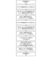
- FIG. This is camera setting processing executed by the inspection target image transmission system 1 .
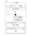
- 4 is a diagram schematically showing an example of setting contents set by the inspection terminal 10.
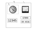
- FIG. 3 is a diagram schematically showing an example of an image of an inspection target 3;
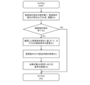
- FIG. This is the first instruction creation process executed by the inspection target image transmission system 1 .
- This is a second instruction creation process executed by the inspection target image transmission system 1 .
- This is the imaging process executed by the inspection target image transmission system 1 .
- This is recording processing executed by the inspection target image transmission system 1 .
- 4 is a diagram showing a flowchart of inspection data transmission processing executed by the inspection target image transmission system 1.
- FIG. 4 is a diagram schematically showing an example of trimming an image 40 captured by a camera 20;
- FIG. 4 is a diagram schematically showing an example of an
- FIG. 1 is a diagram for explaining an outline of an inspection target image transmission system 1.
- the inspection target image transmission system 1 captures an inspection terminal 10 possessed by an inspection worker who performs inspection work, an image of the inspection target 3, and records a sound around the inspection target 3, and transmits the captured image and the recorded voice. to the inspection terminal 10.
- the inspection terminal 10 and the camera 20 are connected for data communication.
- the camera 20 is a device capable of capturing images, such as a visible light camera, an X-ray camera, a magnetic resonance camera, or the like.
- An image is a still image or a moving image.
- the inspection object 3 is a meter (for example, a circular type, rectangular type, Nanasegu type, counter type, bar type, lamp type), and the camera 20 can capture an image of this meter. It is installed in a suitable position. Further, each process executed by the inspection terminal 10 is executed by a predetermined application.
- the camera 20 periodically confirms whether or not there is a photographing condition instruction and a trimming condition instruction in a place for the photographing condition instruction and the trimming condition instruction (step S1).
- the shooting conditions include, for example, shooting schedule, shooting timing, shooting frequency, shooting time, shooting range, resolution, presence/absence of flash, intensity of flash, presence/absence of automatic flash, EV (Exposure Value) value, shutter. These are conditions related to settings of the camera 20 itself, such as speed.
- the photographing condition instruction instructs the camera 20 of these photographing conditions.
- the trimming condition is, for example, a condition relating to the area for trimming the image of the inspection target 3 captured by the camera 20 .
- Trimming in the present invention means cutting out only a specified area, deleting other areas as unnecessary areas, and generating an image of only the specified area.
- the trimming condition instruction instructs the camera 20 on this trimming condition.
- the place is, for example, a cloud computer or the camera 20 itself, and is a physical or virtual place where the shooting condition instructions and the trimming condition instructions are placed.
- the inspection terminal 10 receives input of shooting conditions and trimming conditions, and creates shooting condition instructions and trimming condition instructions based on the accepted shooting conditions and trimming conditions.
- the inspection terminal 10 transmits the photographing condition instruction and the trimming condition instruction to the location of the cloud computer.
- the cloud computer receives the photographing condition instructions and the trimming condition instructions, and stores them in a place set for itself.
- the camera 20 creates shooting condition instructions and trimming condition instructions from the sensing results of a pressure sensor, infrared sensor, etc. attached to itself (for example, detecting pressing of a shooting button, detecting a moving object), and creates shooting. Place the condition instruction and the trimming condition instruction in the place set for yourself. The camera 20 periodically confirms whether or not there is a photographing condition instruction and a trimming condition instruction in this cloud computer or a place set in itself.
- the camera 20 changes the photographing conditions based on the confirmed photographing condition instructions, and photographs the image of the inspection object 3 (step S2).
- the camera 20 changes the photographing conditions by overwriting all or part of the photographing conditions in the confirmed photographing condition instruction on the photographing conditions up to that point.
- the camera 20 captures an image of the inspection object 3 based on the changed capturing conditions.
- the camera 20 trims the photographed image of the inspection object 3 based on the confirmed trimming condition instruction (step S3).
- the camera 20 changes the trimming condition by overwriting all or part of the trimming condition in the confirmed trimming condition instruction on the existing trimming condition.
- the camera 20 trims the image of the inspection target 3 based on the changed trimming conditions.
- the camera 20 cuts out only the area specified in the trimming conditions, and deletes the other areas as unnecessary areas. That is, the camera 20 generates an image of only the area designated by this trimming condition instruction.
- the camera 20 After switching from the standby communication method to the transmission communication method, the camera 20 transmits the trimmed image of the inspection target 3 (step S4).
- the camera 20 switches from a standby communication method, which is a communication method during standby (a state in which images are not being transmitted), to a transmission communication method, which is a communication method for transmission (a state in which images are being transmitted), and performs trimming.
- the image of the object 3 to be inspected is transmitted to the inspection terminal 10 .
- the camera 20 switches from the transmission communication method to the standby communication method and waits (step S5).
- the standby communication method has an average current consumption of 1 mA or less per hour
- the transmission communication method has an average current consumption of more than 1 mA per hour.
- the inspection terminal 10 receives the trimmed image of the inspection target 3 transmitted by the camera 20 .
- the inspection worker performs remote inspection of the inspection object 3 by viewing this image.
- the inspection target image transmission system 1 described above is configured by the inspection terminal 10 and the camera 20.
- the inspection terminal 10 and a computer for example, a computer having a server function or a cloud computer
- the camera 20 may constitute a system.
- the process of creating the shooting condition instructions and the trimming condition instructions, the sending process of the shooting condition instructions and the trimming condition instructions, and the receiving process of the image, which are executed by the inspection terminal 10, are performed via the computer.
- the computer receives various inputs from the inspection terminal 10, executes processing necessary for the received input contents, receives an image from the camera 20, and transmits the image to the inspection terminal 10. display.
- remote inspection can be performed with power saving, and power saving can be achieved by improving inspection efficiency.
- the inspection object image transmission system 1 is composed of an inspection terminal 10 and a camera 20 installed at a predetermined position around the inspection object 3, and is connected via a network 9 such as a public line network so as to be capable of data communication. System.
- the inspection target image transmission system 1 may include other terminals, devices, and the like. In this case, the inspection target image transmission system 1 executes the processing described later by using any one of the inspection terminal 10, the camera 20, other terminals and devices, or a combination thereof.
- the inspection object 3 is the meter of the instrument as described above.
- the inspection target image transmission system 1 may be a system having a personal computer or computer having a server function, or a cloud computer composed of a plurality of computers.
- a cloud computer in this specification is a computer that uses any computer in a scalable manner to perform a specific function, or includes multiple functional modules to realize a certain system, and uses the functions in a free combination. It can be anything.
- the inspection target image transmission system 1 executes each process executed by the inspection terminal 10 described later by this computer, and outputs the result of the process to the inspection terminal 10 or the camera 20, or to the inspection terminal 10.
- the results of processing executed by the terminal 10 are stored on this computer, and are output to the camera 20 in response to requests from the camera 20 .
- the inspection terminal 10 is a mobile terminal such as a smart phone or a tablet terminal possessed by an inspection worker, a computer such as a personal computer, an HMD (Head Mounted Display) such as smart glasses, or the like.
- the inspection terminal 10 includes a CPU (Central Processing Unit), GPU (Graphics Processing Unit), RAM (Random Access Memory), ROM (Read Only Memory), etc.
- a device or the like is provided for enabling communication with the device or the like.
- the inspection terminal 10 includes, as a processing unit, various devices that execute various processes.
- the control unit reads a predetermined program and cooperates with the communication unit to obtain a test image acquisition module, a camera setting content transmission module, an imaging condition instruction transmission module, a recording condition instruction transmission module, and trimming.
- a condition instruction transmission module and an inspection data reception module are realized.
- the control unit reads a predetermined program, and cooperates with the processing unit to perform a shooting schedule setting module, a recording schedule setting module, a resolution setting module, a camera setting module, a communication method setting module, a trimming module, and a A setting module, an imaging condition input reception module, an imaging condition instruction creation module, a recording condition input reception module, a recording condition instruction creation module, a trimming condition input reception module, and a trimming condition instruction creation module are realized.
- the camera 20 is installed at a predetermined position around the inspection object 3, and is a device for taking an image, recording a sound, transmitting an image, and the like.
- the camera 20 includes a CPU (Central Processing Unit), a GPU (Graphics Processing Unit), a RAM (Random Access Memory), a ROM (Read Only Memory), and the like.
- a confirmation unit 21 that periodically confirms whether or not there are a device for enabling communication with , equipment, etc., and a photographing condition instruction and a trimming condition instruction in the storage area.
- a transmission unit 22 or the like for transmitting the trimmed image to the inspection terminal 10 is provided.
- the camera 20 also includes a data storage unit such as a hard disk, a semiconductor memory, a storage medium, or a memory card as a storage unit.
- the camera 20 includes, as a processing unit, a device for executing various processes, a photographing unit 23 for photographing an image of the inspection object 3, a trimming unit 24 for trimming the photographed image, and a transmission communication after the image is transmitted.
- a standby unit 25 or the like that waits after switching from the system to the standby communication system is provided.
- the control unit reads a predetermined program, and cooperates with the communication unit to implement a camera setting content reception module, a sensing result acquisition module, and an inspection data transmission module. Also, in the camera 20, the control unit reads a predetermined program and cooperates with the storage unit to realize a camera setting content storage module, a shooting condition instruction storage module, a sound recording condition instruction storage module, and a trimming condition instruction storage module. do. In the camera 20, the control unit reads a predetermined program, and cooperates with the processing unit to create a shooting condition instruction creation module, a recording condition instruction creation module, a trimming condition instruction creation module, a confirmation module, and a condition instruction presence/absence determination. A module, an imaging condition changing module, an imaging module, a recording condition changing module, a recording module, a trimming condition changing module, a trimming module, and a communication method switching module are realized.
- FIG. 3 is a diagram showing a flowchart of camera setting processing executed by the inspection terminal 10. As shown in FIG. Processing executed by each module described above will be described together with this processing.
- This camera setting process is a process realized by causing each module to execute a process using a predetermined application.
- the imaging schedule setting module sets an imaging schedule for imaging the inspection object 3 (step S10).
- the shooting schedule means the timing at which the camera 20 takes an image of the inspection target 3 .
- the shooting schedule is the number and time of shooting in a day. As described above, the imaging schedule is once a day at a predetermined time, multiple times a day at a plurality of predetermined times, every hour, or the like.
- the shooting schedule setting module accepts inputs of the number of times and time. As a method of accepting the input, there are a method of selecting a schedule desired by the inspection worker from among a plurality of imaging schedules, a method of directly inputting the number of times and a time desired by the inspection worker, and the like.
- the shooting schedule setting module sets the shooting schedule based on the received number of times and time.
- the recording schedule setting module sets a recording schedule for recording sounds around the inspection object 3 (step S11).
- the recording schedule means the timing at which the camera 20 records sounds around the inspection target 3 (around the camera 20).
- the recording schedule is the timing of the shooting schedule, that is, a predetermined time interval before and after the camera 20 takes an image. It is the time interval from before the specified time when the camera 20 captures an image to after the specified time after the capture.
- the recording schedule is 1 second before and after shooting, 5 seconds before and after, 10 seconds before and after shooting, and the like. For example, in the case of 1 second before and after photographing, it is the time interval from 1 second before the camera 20 photographs the image to 1 second after the photographing of the image.
- a recording schedule may be set for time intervals before and after shooting, before shooting, or after shooting.
- the recording scheduling module accepts time inputs.
- the inspection worker selects the recording schedule desired by the inspection worker from among a plurality of recording schedules, or the inspection worker directly inputs the time desired by the inspection worker.
- a recording scheduling module schedules recordings based on the received times.
- the resolution setting module sets the resolution of the image of the inspection object 3 (step S12).
- the resolution designates image quality such as low image quality, high image quality, and standard image quality.
- the resolution setting module accepts input of resolution. As a method of accepting the input, the resolution desired by the inspection worker is selected from a plurality of resolutions, the resolution desired by the inspection worker is directly input, and the like.
- a resolution setting module sets the resolution based on the received resolution.
- the camera setting module sets the settings of the camera 20 that captures the image of the inspection target 3 (step S13).
- the settings of the camera 20 are, for example, presence/absence of flash, intensity of flash, presence/absence of automatic light emission, normal EV value, EV value when illuminance is dark, and shutter speed.
- the camera setting module accepts input of camera 20 settings.
- a method of accepting input there are various methods such as using a preset initial value as it is, selecting a setting desired by an inspection worker from a plurality of settings, and directly inputting a setting desired by an inspection worker. mentioned.
- the camera setting module sets the settings of the camera 20 based on the received settings of the camera 20 .
- the communication method setting module sets the standby communication method and the transmission communication method (step S14).
- the standby communication method means a communication method in which no image is transmitted.
- the transmission communication method means a communication method for transmitting images.
- the standby communication method is a communication method that consumes less current than the transmission communication method, and has an average current consumption of 1 mA or less per hour.
- the communication method for transmission is a communication method having an average current consumption of more than 1 mA per hour and having at least the current consumption required for transmitting the image after trimming by the camera 20 .
- the communication method setting module receives inputs of a standby communication method and a transmission communication method, respectively.
- the inspection worker selects a desired one from a combination of a standby communication method and a transmission communication method with a preset current consumption using a preset initial value of current consumption. , the inspection worker selects the current consumption desired from among a plurality of consumption currents, and the inspection worker directly inputs the consumption current desired by the inspection worker.
- the selected combination can be changed.
- the communication method setting module sets the standby communication method and the transmission communication method based on the received standby communication method and transmission communication method. By reducing the current consumption of the normal standby communication method to 1 mA or less, the effect of power saving is enhanced.
- FIG. 4 shows an example of setting contents set by the inspection terminal 10.
- the figure shows the setting contents of image quality, presence/absence of flash, presence/absence of automatic flash emission, flash intensity, shooting schedule, and recording schedule. Descriptions of other set contents are omitted.
- the inspection terminal 10 has high image quality, flash, automatic flash emission, standard flash intensity, and a shooting schedule of one day. 24 times per hour (every hour), and the recording schedule is set to ⁇ 5 seconds at the time of shooting.
- the trimming setting module sets a region for trimming the image of the inspection object 3 (step S15). Trimming in the present invention means cutting out only a specified area, deleting other areas as unnecessary areas, and generating an image of only the specified area.
- the test image acquisition module acquires an image of the inspection target 3 captured by the camera 20 in advance. The images acquired by the test image acquisition module at this time are images captured when the camera 20 is installed, or images captured by the camera 20 at other timings.
- the trimming setting module sets a trimming area 31 for the acquired image 30 of the inspection target 3 shown in FIG. The trimming setting module receives an input such as a tap operation on this image 30 displayed on its own display unit or the like.
- the trimming setting module accepts the input of the trimming area 31 by enclosing the inspection worker's desired location of the inspection target 3 with a rectangle, circle, or the like, or designating the inspection target 3 location.
- the trimming setting module sets the trimming region 31 that has received this input as the trimming region 31 of the image 30 .
- the trimming area 31 set here is set as the coordinates in the image 30 and the position in the image 30 .
- each of the set areas to be trimmed is cut out and an image of each specified area is generated.
- the camera setting content transmission module transmits the camera setting content to the camera 20 (step S16).
- the camera setting content transmission module transmits the shooting schedule, recording schedule, resolution, camera 20 setting, standby communication method, transmission communication method, and trimming area set by the processing of steps S10-15 described above to the camera setting content. , and is transmitted to the camera 20 .
- the camera setting content reception module receives the camera setting content.
- the camera setting content storage module stores the camera setting content.
- the camera 20 is set by storing the camera setting contents.
- the camera 20 performs the shooting process (recording condition instruction exists, photographing processing and recording processing) and inspection data transmission processing are executed. After the transmission is completed, the camera 20 switches from the transmission communication method to the standby communication method and waits. Since the current consumption of the standby communication method is lower than that of the transmission communication method, power saving is achieved compared to standby with the transmission communication method.
- the above is the camera setting process.
- FIG. 6 is a diagram showing a flowchart of the first instruction creation process executed by the inspection terminal 10. As shown in FIG. Processing executed by each module described above will be described together with this processing.
- This first instruction creation process is a process related to the periodical confirmation process (step S1) as to whether or not there is a photographing condition instruction, and is performed after the camera setting process described above.
- the imaging condition input reception module receives input of imaging conditions for the camera 20 (step S20).
- the shooting conditions include conditions related to shooting such as shooting schedule, shooting timing, shooting frequency, shooting time, shooting range, resolution, presence or absence of flash, flash intensity, presence or absence of automatic light emission, EV value, shutter speed, etc. is a condition related to the setting of the camera 20 of .
- the imaging condition input reception module receives input of imaging conditions. At this time, the imaging condition input reception module may receive input of all items of the imaging conditions described above, or may receive input of some of the items.
- a method of accepting the input there are a method of selecting the photographing conditions desired by the inspection worker, a direct input of the photographing conditions desired by the inspection worker, and the like. Note that the imaging conditions are not limited to the above examples, and may include other items.
- the shooting condition instruction creation module creates shooting condition instructions based on the received shooting conditions of the camera 20 (step S21).
- the photographing condition instruction is for instructing the camera 20 of the photographing conditions.
- the imaging condition instruction creating module creates an imaging condition instruction in a predetermined format based on the imaging conditions.
- the imaging condition instruction transmission module transmits the created imaging condition instruction to the cloud computer (step S22).
- the imaging condition instruction transmission module transmits this imaging condition instruction to the cloud computer, and the cloud computer receives this imaging condition instruction.
- the cloud computer stores the received imaging condition instructions in a preset place.
- a storage area is a physical or virtual location, as described above.
- the cloud computer stores the received photographing condition instructions in a storage unit or the like, thereby keeping the photographing condition instructions in place.
- the recording condition input acceptance module accepts the input of the recording condition of the camera 20 (step S23).
- the recording conditions are, for example, recording schedule, recording time, recording timing, and other conditions related to recording.
- the recording condition input reception module receives input of recording conditions. At this time, the recording condition input receiving module may receive input of all the items of the above-described recording conditions, or may receive input of some of the items.
- the inspection worker selects the desired recording conditions, the inspection worker directly inputs the recording conditions desired, and the like. Recording conditions are not limited to the above examples, and may include other items.
- the recording condition instruction creating module creates a recording condition instruction based on the received recording conditions of the camera 20 (step S24).
- the recording condition instruction is for instructing the camera 20 of the recording condition.
- a recording condition instruction creation module creates a recording condition instruction in a predetermined format based on the recording conditions.
- the recording condition instruction transmission module transmits the created recording condition instruction to the cloud computer (step S25).
- the recording condition instruction transmission module transmits this recording condition instruction to the cloud computer, and the cloud computer receives this recording condition instruction.
- the cloud computer stores the received recording condition instructions in a preset place.
- a storage area is a physical or virtual location, as described above.
- the cloud computer stores the received recording condition instructions in a storage unit or the like, thereby keeping the recording condition instructions in place.
- the trimming condition input reception module receives input of the trimming conditions for the camera 20 (step S26).
- the trimming condition is, as described above, a condition regarding the area for trimming the image of the inspection target 3 captured by the camera 20 .
- the trimming condition input reception module receives input of trimming conditions.
- the input reception method may be the same as the input method for the trimming area 31 in which the trimming setting module in the process of step S15 described above receives the input.
- the trimming condition instruction creating module creates a trimming condition instruction based on the received trimming conditions of the camera 20 (step S27).
- the trimming condition instruction is for instructing the camera 20 of the trimming condition.
- a trimming condition instruction creating module creates a trimming condition instruction in a predetermined format based on this trimming condition.
- the trimming condition instruction transmission module transmits the created trimming condition instruction to the cloud computer (step S28).
- the trimming condition instruction transmission module transmits this trimming condition instruction to the cloud computer, and the cloud computer receives this trimming condition instruction.
- the cloud computer stores the received trimming condition instructions in a preset place.
- a storage area is a physical or virtual location, as described above.
- the cloud computer stores the received trimming condition instructions in a storage unit or the like, thereby keeping the trimming condition instructions in place.
- the inspection terminal 10 does not necessarily have to perform all of the processes of steps S20 to S28 described above, and at least performs the processes related to the photographing conditions (steps S20 to S22) and the processes related to the trimming conditions (steps S26 to S28). Any configuration is fine. Further, the inspection terminal 10 may be configured to simultaneously receive input of photographing conditions, input of recording conditions, and input of trimming conditions. In this case, the inspection terminal 10 may transmit to the cloud computer together the imaging condition instruction, the recording condition instruction, and the trimming condition instruction to be created.
- FIG. 7 is a diagram showing a flowchart of the second instruction creation process executed by the camera 20. As shown in FIG. Processing executed by each module described above will be described together with this processing.
- the second instruction creation process is a process related to the periodical confirmation process (step S1) as to whether or not there is an imaging condition instruction described above, and is performed after the camera setting process described above. Further, either the above-described first instruction creation process or the second instruction creation process may be performed, or both of them may be performed. .
- the sensing result acquisition module acquires the sensing result of the sensor attached to the camera 20 (step S30).
- the sensors attached to the camera 20 are pressure sensors, infrared sensors, etc., as described above.
- the sensing results are, as described above, detection of pressing of the shooting button, detection of a moving object, and the like.
- the sensor transmits the sensing result detected by itself to the camera 20 .
- the sensing result acquisition module acquires the sensing result by receiving this sensing result. Note that the types of sensors and sensing results are not limited to the examples described above, and can be changed as appropriate.
- the imaging condition instruction creating module creates an imaging condition instruction based on the obtained sensing result (step S31).
- the imaging condition instruction creating module creates an imaging condition instruction in a predetermined format based on the obtained sensing result.
- the photographing condition instruction storage module stores the created photographing condition instruction in a place set in advance for itself (step S32).
- a storage location is a physical or virtual location, similar to the storage location in the cloud computer described above.
- the imaging condition instruction storage module stores the created imaging condition instruction in the storage unit or the like, thereby placing the imaging condition instruction in a place.
- the recording condition instruction creating module creates a recording condition instruction based on the obtained sensing result (step S33).
- a recording condition instruction creation module creates a recording condition instruction in a predetermined format based on the obtained sensing result.
- the recording condition instruction storage module stores the created recording condition instruction in a place preset for itself (step S34).
- a storage location is a physical or virtual location, similar to the storage location in the cloud computer described above.
- the recording condition instruction storage module stores the created recording condition instruction in the storage unit or the like, thereby keeping the recording condition instruction in place.
- the trimming condition instruction creating module creates a trimming condition instruction based on the acquired sensing result (step S35).
- a trimming condition instruction creation module creates a trimming condition instruction in a predetermined format based on the obtained sensing result.
- the trimming condition instruction storage module stores the created trimming condition instruction in a place preset for itself (step S36).
- a storage location is a physical or virtual location, similar to the storage location in the cloud computer described above.
- the trimming condition instruction storage module stores the created trimming condition instruction in a storage unit or the like, thereby storing the photographing condition instruction.
- the camera 20 does not necessarily have to perform all of the processes of steps S30 to S36 described above, but at least the process of obtaining sensing results (step S30), the process of photographing conditions (steps S31 and S32), and the process of trimming conditions. (Steps S35 and S36) may be used. Further, the camera 20 may be configured to simultaneously create the shooting condition instructions, the recording condition instructions, and the trimming condition instructions. In this case, the camera 20 should put the created photographing condition instructions, recording condition instructions, and trimming condition instructions together in a place.
- FIG. 8 is a diagram showing a flowchart of photographing processing executed by the camera 20. As shown in FIG. Processing executed by each module described above will be described together with this processing.
- This photographing process is the details of the confirming process for the presence or absence of the photographing condition instruction (step S1) and the photographing process of the image of the inspection target 3 (step S2). This process is performed after the creation process.
- the confirmation module periodically confirms whether or not there is a photographing condition instruction in the place for photographing condition instructions and whether or not there is a trimming condition instruction in the place for trimming condition instructions (step S40).
- the confirmation module periodically confirms the shooting condition instructions placed in the storage area of the cloud computer by the above-described first instruction creation process or the shooting condition instructions placed in the storage area of the camera 20 by the above-described second instruction creation process. .
- the confirmation module periodically confirms the trimming condition instructions placed in the location of the cloud computer by the above-described first instruction creation process or the trimming condition instructions placed in the location of the camera 20 by the second instruction creation process. confirm.
- the confirmation module accesses the cloud computer and confirms the shooting condition instructions and the trimming condition instructions placed in the cloud computer. Alternatively, the confirmation module confirms the photographing condition instructions placed on the place where the camera 20 is placed.
- the condition instruction presence/absence determination module determines whether or not there are photographing condition instructions and trimming condition instructions in the checked storage area (step S41). If the condition instruction presence/absence determination module does not have the photographing condition instruction and the trimming condition instruction in the confirmed place (step S41 NO), the photographing condition confirmation module performs the above-described photographing condition instruction confirmation process (step S40) again. Execute.
- the photographing condition change module changes the camera 20 based on the photographing condition instruction that has been confirmed.
- the photographing conditions are changed (step S42).
- the imaging condition change module changes the resolution (image quality) at which the image is captured.
- the photographing condition change module may be configured to change the resolution of the photographed image. In this case, the imaging condition change module enlarges/reduces the image, changes dpi (dots per inch), compresses the image, etc., and changes the resolution.
- the photographing condition change module similarly changes the photographing conditions at the time of image photographing and the photographing conditions after image photographing for other photographing conditions as well.
- the photographing condition change module changes the camera setting contents set in the camera 20 by the camera setting process described above, based on the photographing conditions included in the photographing condition instruction and the conditions concerning the settings of the camera 20 .
- the photographing condition change module maintains the camera setting contents set in the camera 20 by the camera setting process described above for the conditions not included in the photographing condition instruction.
- the camera setting content storage module stores the changed camera setting content (step S43).
- the camera setting content storage module overwrites the photographing conditions before change with the confirmed photographing conditions.
- the photographing module photographs an image of the inspection object 3 (step S44).
- the capture module captures this image based on the conditions in the changed camera settings.
- the configuration in which the imaging module performs imaging may be any configuration in which a device having a general imaging function is configured to capture an image.
- the above is the shooting process. If the computer 10 confirms the photographing condition instruction again and changes the photographing condition, it overwrites the previously used photographing condition with the newly confirmed photographing condition, and changes the camera settings. do.
- the shooting condition changing module changes the shooting conditions in the camera settings to the regular shooting schedule.
- a configuration is also possible in which images of the inspection target 3 are captured based on a specific image capturing schedule.
- the computer 10 captures an image of the inspection target 3 based on the changed camera setting contents regardless of the above-described presence/absence determination processing of the imaging condition instruction (step S41) at the date and time of the imaging schedule.
- the camera 20 can also be configured to record sounds around the inspection object 3 based on the recording schedule in the camera setting contents in conjunction with this regular shooting schedule.
- FIG. 9 is a diagram showing a flowchart of recording processing executed by the camera 20. As shown in FIG. Processing executed by each module described above will be described together with this processing.
- the main sound recording process is a process related to the above-described photographing process, and is a process performed simultaneously with or after the above-described photographing process.
- the confirmation module confirms whether or not there is a recording condition instruction in the storage for the recording condition instruction (step S50).
- the confirmation module confirms the recording condition instructions placed on the storage of the cloud computer by the above-described first instruction creation process or the recording condition instructions placed on the storage of the camera 20 by the above-described second instruction creation process.
- the validation module accesses the cloud computer and validates the recording condition instructions placed on the cloud computer. Alternatively, the verification module verifies the recording condition instructions placed in the camera 20 storage.
- the condition instruction presence/absence determination module determines whether or not there is a recording condition instruction at the checked storage location (step S51). If the condition instruction presence/absence determination module does not indicate a recording condition instruction in the checked storage area (step S51 NO), the computer 10 terminates this recording process.
- the recording condition change module changes the recording condition of the camera 20 based on the confirmed recording condition instruction. (step S52).
- the recording condition change module changes the camera setting contents set in the camera 20 by the camera setting process described above, based on the conditions related to recording included in the recording condition instruction. At this time, the recording condition change module maintains the camera setting contents set in the camera 20 by the camera setting process described above for conditions not included in the recording condition instruction.
- the camera setting content storage module stores the changed camera setting content (step S53).
- the camera setting content storage module overwrites the recording conditions before change with the confirmed recording conditions.
- the recording module records sounds around the inspection object 3 (step S54).
- the recording module records this sound based on the conditions in the changed camera settings.
- the configuration in which the recording module performs recording may be any configuration in which a device having a general recording function records voice.
- the above is the recording process.
- the computer 10 confirms the recording condition instruction again, and if the recording condition is changed, overwrites the previously used recording condition with the newly confirmed recording condition, and changes the camera settings. do.
- the photographing process and the sound recording process described above are a series of processes, and the computer 10 executes the sound recording process during or after the photographing process is being executed. If the computer 10 cannot confirm the recording condition instruction (step S51 NO) in the recording condition instruction presence/absence determination process (step S51) in the recording process described above, the inspection data transmission process described later determines whether the inspection object 3 If the configuration processing excluding the surrounding voice is performed and the recording condition instruction is confirmed (step S51 YES), the configuration processing including this voice is performed.
- the recording condition change module changes the recording conditions in the camera settings to this regular recording schedule. It is also possible to record the surrounding sounds of the inspection object 3 based on such a recording schedule. At this time, at the timing of the recording schedule, the computer 10 records the surrounding sounds of the inspection object 3 based on the changed camera settings, regardless of the above-described recording condition instruction presence/absence determination processing (step S51). . That is, when the camera 20 changes the shooting conditions to a regular shooting schedule in the shooting process described above and further changes the recording conditions to a regular recording schedule in the main sound recording process, the camera 20 performs an inspection based on these. An image of the object 3 is photographed and sounds around the inspection object 3 are recorded.
- FIG. 10 is a diagram showing a flowchart of inspection data transmission processing executed by the camera 20. As shown in FIG. Processing executed by each module described above will be described together with this processing.
- This inspection data transmission process is the details of the image trimming process (step S3), the image transmission process (step S4), and the standby process (step S5), and is a process performed after the above-described photographing process and sound recording process. be. Note that this inspection data transmission process will be described by taking as an example a case where both the image captured by the image capturing process and the sound recorded by the sound recording process are used.
- the trimming condition change module changes the trimming condition of the camera 20 based on the confirmed trimming condition instruction (step S60). For example, the trimming condition change module enlarges the trimming area of the captured image when changing the trimming condition enlarges the trimming area. In addition, other trimming condition changes such as reduction, change, addition, etc. of the area to be trimmed are similarly reduced, changed, added, etc. to the area to be trimmed.
- the trimming condition change module changes the camera setting contents set in the camera 20 by the camera setting process described above. At this time, the trimming condition change module maintains the camera setting contents set in the camera 20 by the camera setting process described above for conditions not included in the trimming condition instruction.
- the camera setting content storage module stores the changed camera setting content (step S61).
- the camera setting content storage module overwrites the trimming conditions before change with the confirmed trimming conditions.
- the trimming module trims the captured image based on the confirmed trimming condition instruction (step S62).
- the trimming module determines the trimming area 41 in the captured image 40 shown in FIG. 11 based on the confirmed trimming condition instruction.
- the trimming module determines the trimming area 41 in the captured image 40 to be the same location as the confirmed trimming condition instruction.
- the trimming module trims the determined trimming area 41 .
- the trimming module deletes the area other than the trimming area 41 of the image 40 as an unnecessary area.
- the trimming module trims this image 40 to generate a trimmed image 42 (see FIG. 12) of only the region 41 to be trimmed.
- the trimming module trims each trimming region when a plurality of trimming regions are set.
- the trimming module removes unnecessary areas of the image other than each trimmed area.
- the crop module generates an image of each cropped region respectively. That is, when a plurality of trimming areas are set, the trimming module generates an image according to the number of set trimming areas.
- the communication method switching module switches from the standby communication method to the transmission communication method (step S63).
- the standby communication method is, for example, a communication method with an average current consumption of 1 mA or less per hour.
- the transmission communication method is a communication method in which the average current consumption per hour is greater than 1 mA.
- the communication method switching module switches the communication method from the standby communication method to the transmission communication method based on the communication method set by the camera settings. Since the current consumption of the camera 20 increases when the communication method is switched, it becomes possible to transmit the trimmed image 42 to the inspection terminal 10 . After the transmission is completed, the communication system for transmission is switched to the communication system for standby and then waits. Since the current consumption of the standby communication method is lower than that of the transmission communication method, power saving is achieved compared to standby with the transmission communication method.
- the inspection data transmission module transmits the trimmed image 42, the recorded voice, the setting information and the status information as inspection data to the inspection terminal 10 (step S64).
- the setting information is information related to camera settings such as the area to be trimmed, firmware version, exposure adjustment value, flash intensity, and resolution.
- the state information is information about the state of the camera 20 itself, such as the remaining battery level, radio wave intensity, and error log.
- the inspection data transmission module transmits to the inspection terminal 10 inspection data in which the trimmed image 42 , recorded voice, setting information, and state information are associated with each other.
- the inspection data receiving module receives this inspection data.
- the inspection data display module displays this inspection data. An inspection worker can perform remote inspection by viewing this inspection data.
- the communication method switching module switches from the transmission communication method to the standby communication method (step S65).
- the communication method switching module switches the communication method from the transmission communication method to the standby communication method based on the communication method set by the camera settings. By switching the communication method, the camera 20 consumes less current, which makes it possible to save power.
- the communication system for transmission is switched to the communication system for standby, and then the system waits. Since the current consumption of the standby communication method is lower than that of the transmission communication method, power saving is achieved compared to standby with the transmission communication method.
- the above is the inspection data transmission process. If the computer 10 confirms the trimming condition instruction again and changes the trimming condition, it overwrites the previously used trimming condition with the newly confirmed trimming condition, and changes the camera settings. do.
- the inspection target image transmission system 1 can also change the camera setting content set by the camera setting process described above based on the result of the inspection data transmission process described above.
- the inspection terminal 10 changes the previously set camera settings by executing the camera setting process described above again.
- the inspection terminal 10 changes the setting contents of the camera by receiving an input to change the setting from the inspection worker. It should be noted that it is also possible to change the set camera setting contents regardless of the result of the inspection data transmission process described above.
- the inspection terminal 10 changes the photographing schedule by executing the above-described photographing schedule setting process (step S10) again.
- the schedule interval of the imaging schedule is changed so as to be widened, and when the frequency of grasping the state of the inspection object 3 is increased, the schedule interval of the photography schedule is changed so as to be narrowed. Further, when the frequency of grasping the state of the inspection object 3 is to be decreased, the schedule interval of the imaging schedule is changed to be wider.
- the inspection terminal 10 changes the recording schedule by executing the above-described recording schedule setting process (step S11) again. To increase power saving, change the schedule interval of the recording schedule to be narrower.
- the inspection terminal 10 changes the resolution by executing the above-described image resolution setting process (step S12) again.
- the resolution is changed to be higher, and when there is no problem even if the image quality is lowered or when power saving is to be strengthened, the resolution is changed to be lower.
- the inspection terminal 10 changes the setting by executing the setting process (step S13) of the setting of the camera 20 described above again.
- the presence/absence of flash, flash intensity, ON/OFF of automatic flash emission, normal EV value, EV value when illuminance is dark, shutter speed, etc. are changed.
- the inspection terminal 10 changes the communication method by executing the above-described standby communication method and transmission communication method setting process (step S14) again.
- each of the standby communication method and the transmission communication method may be changed, or a combination thereof may be changed.
- the current of each communication method is changed to the combination with the lowest one, and in order to make the image to be transmitted clearer, the current of the communication method for transmission is changed to be increased.
- the inspection terminal 10 changes the setting by executing the trimming region setting process (step S15) again.
- the area to be trimmed is reduced to reduce the image capacity, and when the situation around the inspection object 3 is desired to be grasped, the area to be trimmed is changed to be enlarged.
- the inspection object 3 is explained as a meter of an instrument, but the present invention can be applied even if the inspection object 3 is a container, a street lamp, a river, a trap for catching animals, or the like.
- the inspection target image transmission system 1 executes the inspection data transmission process described above and transmits an image of the inspection target 3, so that the inspection worker can grasp the state of the inspection target 3 based on this image. If the inspection object 3 is a container, the inspection worker will ascertain whether the container is full. If the inspection object 3 is a streetlight, the inspection worker will grasp whether the streetlight is out. When the inspection object 3 is a river, an inspection worker grasps what the water level of the river is. If the inspection object 3 is a trap, the inspector will ascertain whether any animal is caught in the trap. Similarly, when the inspection object 3 is other than the inspection object 3, the inspection operator grasps whether the inspection object 3 has an abnormality.
- the means and functions described above are realized by a computer (including CPU, information processing device, and various terminals) reading and executing a predetermined program.
- the program may be provided, for example, from a computer via a network (SaaS: software as a service) or provided as a cloud service.
- the program may be provided in a form recorded on a computer-readable recording medium.
- the computer reads the program from the recording medium, transfers it to an internal recording device or an external recording device, records it, and executes it.
- the program may be recorded in advance in a recording device (recording medium) and provided from the recording device to the computer via a communication line.
- the present invention is not limited to these embodiments described above.
- the effects described in the embodiments of the present invention are merely enumerations of the most suitable effects resulting from the present invention, and the effects of the present invention are limited to those described in the embodiments of the present invention. isn't it.
- the shooting schedule setting module, the recording schedule setting module, the trimming setting unit 11, the resolution setting module, the camera setting module, the communication method setting module, and the trimming setting module may be included in the camera 20 instead of the inspection terminal 10. .
- An inspection target image transmission system that transmits an image of an inspection target (e.g., instrument meter, container, street lamp, river, animal trap) captured by a camera (e.g., camera 20), a confirmation unit (e.g., confirmation unit 21, confirmation module) that causes the camera to periodically confirm whether or not there is a photographing condition instruction and a trimming condition instruction in a place for the photographing condition instruction and the trimming condition instruction; Based on the confirmed shooting condition instructions, the shooting conditions (for example, shooting schedule, shooting timing, shooting frequency, shooting time, shooting range, resolution, presence/absence of flash, intensity of flash, presence/absence of automatic light emission, EV a photographing unit (for example, a photographing unit 23, a photographing condition changing module, a photographing module) for photographing an image of the inspection object by changing the value, shutter speed); A trimming unit (for example, a trimming unit 24, a trimming condition change module, a trimming module )and, A transmission unit (for example, a transmission unit 22, a communication method switching module, an inspection data transmission module
- power saving is achieved by enabling remote inspection with power saving and improving inspection efficiency.
- the confirmation unit causes the camera to periodically confirm whether or not there is a recording condition instruction in the storage location;
- the photographing unit causes the camera to change the recording condition based on the confirmed recording condition instruction to record the sound around the inspection target,
- the transmission unit transmits the recorded sound around the inspection target,
- the inspection target image transmission system according to (1).
- inspection can be performed not only by images but also by surrounding sounds during inspection. Even if the inspection worker or manager cannot determine the state of the inspection object from the image alone, the surrounding sounds make it easier for the inspection worker or manager to determine the state of the inspection object.
- the standby communication method is a communication method with an average current consumption of 1 mA or less per hour.
- the inspection target image transmission system according to (1) is a communication method with an average current consumption of 1 mA or less per hour.
- the power saving effect is further enhanced.
- the trimming setting unit sets the resolution of the image to be inspected;
- the trimming unit trims the image to be inspected at the set resolution.
- the confirming unit again confirms whether or not there is the photographing condition instruction and the trimming condition instruction; the photographing unit overwrites the previously used photographing conditions with the newly confirmed photographing conditions to photograph the image of the inspection target;
- the trimming unit overwrites the previously used trimming condition with the newly confirmed trimming condition to trim the image to be inspected.
- an imaging schedule changing unit that changes the imaging condition to the periodic imaging schedule when the imaging condition instruction includes a regular imaging schedule; further comprising The imaging unit causes the camera to capture an image of the inspection target based on the changed periodic imaging schedule.
- a camera setting changing unit for example, a photographing condition changing module that changes settings of the camera based on the photographing condition instruction
- selection means e.g., communication method setting module for selecting a combination of a standby communication method for making the camera stand by and a transmission communication method for transmitting the trimmed inspection target image;
- the transmission unit transmits setting information (eg, area to be trimmed, firmware version, exposure adjustment value, flash intensity, resolution) and status information (eg, remaining battery level, radio wave intensity, error log) of the camera. send along with The inspection target image transmission system according to (1).
- setting information eg, area to be trimmed, firmware version, exposure adjustment value, flash intensity, resolution
- status information eg, remaining battery level, radio wave intensity, error log
- An inspection target image transmission method executed by a computer that transmits an inspection target image captured by a camera, causing the camera to periodically check whether or not there is a photographing condition instruction and a trimming condition instruction in a place for the photographing condition instruction and the trimming condition instruction (for example, step S40); a step (for example, steps S42 and S44) of causing the camera to change the photographing conditions and photograph the image of the inspection target based on the confirmed photographing condition instructions; a step (for example, steps S60 and S62) of causing the camera to change the trimming condition based on the confirmed trimming condition instruction and trimming the image of the inspection object captured by the camera; a step of causing the camera to switch from a communication mode for standby to a communication mode for transmission, and then transmitting the trimmed image of the inspection object (for example, steps S63 and S64); a step of causing the camera to wait by switching from the communication method for transmission to the communication method for standby after the transmission is completed (for example, step S65);
- An inspection target image transmission method
- step S40 To the computer that transmits the image of the inspection target taken by the camera, causing the camera to periodically check whether or not there is a photographing condition instruction and a trimming condition instruction in a place for the photographing condition instruction and the trimming condition instruction (for example, step S40); a step of causing the camera to change the photographing conditions and photographing the image of the inspection object based on the confirmed photographing condition instruction (for example, steps SS42 and S44); a step of causing the camera to change the trimming condition based on the confirmed trimming condition instruction and trimming the image of the inspection object captured by the camera (for example, steps S60 and S62); a step of causing the camera to switch from a standby communication method to a transmission communication method and then transmitting the trimmed image of the inspection object (for example, steps S63 and S64); a step of causing the camera to wait by switching from the communication method for transmission to the communication method for standby after the transmission is completed (for example, step S65);
Landscapes
- Engineering & Computer Science (AREA)
- Multimedia (AREA)
- Signal Processing (AREA)
- Studio Devices (AREA)
- Closed-Circuit Television Systems (AREA)
Priority Applications (4)
| Application Number | Priority Date | Filing Date | Title |
|---|---|---|---|
| EP21965588.3A EP4447433A4 (en) | 2021-11-24 | 2021-11-24 | System for transmitting inspection target images, method for transmitting inspection target images and program |
| US18/713,282 US12615436B2 (en) | 2021-11-24 | 2021-11-24 | Inspection-target-image transmission system, inspection-target-image transmission method, and program |
| JP2022514834A JP7169035B1 (ja) | 2021-11-24 | 2021-11-24 | 点検対象画像送信システム、点検対象画像送信方法及びプログラム |
| PCT/JP2021/043028 WO2023095214A1 (ja) | 2021-11-24 | 2021-11-24 | 点検対象画像送信システム、点検対象画像送信方法及びプログラム |
Applications Claiming Priority (1)
| Application Number | Priority Date | Filing Date | Title |
|---|---|---|---|
| PCT/JP2021/043028 WO2023095214A1 (ja) | 2021-11-24 | 2021-11-24 | 点検対象画像送信システム、点検対象画像送信方法及びプログラム |
Publications (1)
| Publication Number | Publication Date |
|---|---|
| WO2023095214A1 true WO2023095214A1 (ja) | 2023-06-01 |
Family
ID=83995270
Family Applications (1)
| Application Number | Title | Priority Date | Filing Date |
|---|---|---|---|
| PCT/JP2021/043028 Ceased WO2023095214A1 (ja) | 2021-11-24 | 2021-11-24 | 点検対象画像送信システム、点検対象画像送信方法及びプログラム |
Country Status (4)
| Country | Link |
|---|---|
| US (1) | US12615436B2 (https=) |
| EP (1) | EP4447433A4 (https=) |
| JP (1) | JP7169035B1 (https=) |
| WO (1) | WO2023095214A1 (https=) |
Cited By (1)
| Publication number | Priority date | Publication date | Assignee | Title |
|---|---|---|---|---|
| JPWO2025177546A1 (https=) * | 2024-02-22 | 2025-08-28 |
Citations (9)
| Publication number | Priority date | Publication date | Assignee | Title |
|---|---|---|---|---|
| JP2007228315A (ja) | 2006-02-24 | 2007-09-06 | Mitsubishi Heavy Ind Ltd | 建屋内における構造物の建設工事及び点検支援装置 |
| JP2008283484A (ja) * | 2007-05-10 | 2008-11-20 | Hitachi Kokusai Electric Inc | 監視カメラシステム |
| JP2009200702A (ja) * | 2008-02-20 | 2009-09-03 | Sharp Corp | ネットワークカメラシステム |
| JP2013062696A (ja) * | 2011-09-14 | 2013-04-04 | Mk Seiko Co Ltd | 遠隔地監視システム |
| WO2013072980A1 (ja) * | 2011-11-14 | 2013-05-23 | キヤノン株式会社 | 撮像装置、制御装置、制御方法、及びプログラム |
| JP2014063378A (ja) | 2012-09-21 | 2014-04-10 | Nippon Bilco Co Ltd | 設備点検システムに用いられる管理サーバ |
| JP2017163300A (ja) * | 2016-03-09 | 2017-09-14 | キヤノン株式会社 | 船舶監視装置 |
| JP2018191051A (ja) * | 2017-04-28 | 2018-11-29 | キヤノン株式会社 | 制御装置、制御方法、及びプログラム |
| WO2019049455A1 (ja) * | 2017-09-05 | 2019-03-14 | ソニー株式会社 | 撮像装置、再生装置、制御方法、および制御システム |
Family Cites Families (5)
| Publication number | Priority date | Publication date | Assignee | Title |
|---|---|---|---|---|
| WO2014144628A2 (en) * | 2013-03-15 | 2014-09-18 | Master Lock Company | Cameras and networked security systems and methods |
| JP6521652B2 (ja) * | 2015-02-04 | 2019-05-29 | キヤノン株式会社 | 通信装置、その制御方法、プログラム |
| JP6915399B2 (ja) * | 2017-06-16 | 2021-08-04 | 富士フイルムビジネスイノベーション株式会社 | 情報処理装置及び情報処理プログラム |
| CN114026842B (zh) * | 2019-06-21 | 2025-01-17 | 佳能株式会社 | 图像提供系统及其控制方法 |
| JP7542976B2 (ja) * | 2020-03-27 | 2024-09-02 | キヤノン株式会社 | 通信装置、その制御方法、プログラム |
-
2021
- 2021-11-24 EP EP21965588.3A patent/EP4447433A4/en active Pending
- 2021-11-24 JP JP2022514834A patent/JP7169035B1/ja active Active
- 2021-11-24 US US18/713,282 patent/US12615436B2/en active Active
- 2021-11-24 WO PCT/JP2021/043028 patent/WO2023095214A1/ja not_active Ceased
Patent Citations (9)
| Publication number | Priority date | Publication date | Assignee | Title |
|---|---|---|---|---|
| JP2007228315A (ja) | 2006-02-24 | 2007-09-06 | Mitsubishi Heavy Ind Ltd | 建屋内における構造物の建設工事及び点検支援装置 |
| JP2008283484A (ja) * | 2007-05-10 | 2008-11-20 | Hitachi Kokusai Electric Inc | 監視カメラシステム |
| JP2009200702A (ja) * | 2008-02-20 | 2009-09-03 | Sharp Corp | ネットワークカメラシステム |
| JP2013062696A (ja) * | 2011-09-14 | 2013-04-04 | Mk Seiko Co Ltd | 遠隔地監視システム |
| WO2013072980A1 (ja) * | 2011-11-14 | 2013-05-23 | キヤノン株式会社 | 撮像装置、制御装置、制御方法、及びプログラム |
| JP2014063378A (ja) | 2012-09-21 | 2014-04-10 | Nippon Bilco Co Ltd | 設備点検システムに用いられる管理サーバ |
| JP2017163300A (ja) * | 2016-03-09 | 2017-09-14 | キヤノン株式会社 | 船舶監視装置 |
| JP2018191051A (ja) * | 2017-04-28 | 2018-11-29 | キヤノン株式会社 | 制御装置、制御方法、及びプログラム |
| WO2019049455A1 (ja) * | 2017-09-05 | 2019-03-14 | ソニー株式会社 | 撮像装置、再生装置、制御方法、および制御システム |
Non-Patent Citations (1)
| Title |
|---|
| See also references of EP4447433A4 |
Cited By (1)
| Publication number | Priority date | Publication date | Assignee | Title |
|---|---|---|---|---|
| JPWO2025177546A1 (https=) * | 2024-02-22 | 2025-08-28 |
Also Published As
| Publication number | Publication date |
|---|---|
| JPWO2023095214A1 (https=) | 2023-06-01 |
| US20250024141A1 (en) | 2025-01-16 |
| US12615436B2 (en) | 2026-04-28 |
| EP4447433A1 (en) | 2024-10-16 |
| JP7169035B1 (ja) | 2022-11-10 |
| EP4447433A4 (en) | 2025-03-19 |
Similar Documents
| Publication | Publication Date | Title |
|---|---|---|
| US11710205B2 (en) | Image capturing method and display method for recognizing a relationship among a plurality of images displayed on a display screen | |
| US9491370B2 (en) | Methods and apparatuses for providing guide information for a camera | |
| US7956891B2 (en) | Camera control apparatus and method, and camera control system | |
| JP4768650B2 (ja) | 撮像装置、撮像方法およびプログラム | |
| JP5975099B2 (ja) | 情報処理装置、システム、および記憶媒体 | |
| CN105320695A (zh) | 图片处理方法及装置 | |
| JP2013074376A (ja) | 撮像ガイド装置、撮像装置、撮像ガイド方法、プログラム | |
| JP7169035B1 (ja) | 点検対象画像送信システム、点検対象画像送信方法及びプログラム | |
| JP2004357126A (ja) | 撮像装置、撮像システム及び撮像方法 | |
| JP5677055B2 (ja) | 監視映像表示装置 | |
| US10021253B2 (en) | Imaging apparatus, imaging system, control method for imaging apparatus, and recording medium storing control program used for controlling imaging apparatus | |
| JP5664285B2 (ja) | 情報処理装置、およびカメラ | |
| JP5019228B2 (ja) | 画像撮影装置及びプログラム | |
| JP2013172312A (ja) | 撮影支援システムおよび撮影支援プログラム | |
| JP2025113174A (ja) | 表示方法、及び、プログラム | |
| US20120249840A1 (en) | Electronic camera | |
| JP2020021437A (ja) | 情報処理装置、情報処理方法、プログラム | |
| JP7371999B2 (ja) | 点検対象画像送信システム、点検対象画像送信方法及びプログラム | |
| US12192632B2 (en) | Installation assistance apparatus, installation assistance method, and non-transitory computer-readable storage medium | |
| JP2011119832A (ja) | 画像表示装置および画像表示方法 | |
| JP5332497B2 (ja) | 撮像装置及び画像転送方法 | |
| JP2012151527A (ja) | 電子カメラ | |
| JP5979205B2 (ja) | 情報処理装置、およびカメラ | |
| JP2009124658A (ja) | 撮影シミュレーションシステム | |
| JP4732141B2 (ja) | 赤外線送信装置および赤外線送信範囲表示方法 |
Legal Events
| Date | Code | Title | Description |
|---|---|---|---|
| WWE | Wipo information: entry into national phase |
Ref document number: 2022514834 Country of ref document: JP |
|
| 121 | Ep: the epo has been informed by wipo that ep was designated in this application |
Ref document number: 21965588 Country of ref document: EP Kind code of ref document: A1 |
|
| WWE | Wipo information: entry into national phase |
Ref document number: 18713282 Country of ref document: US |
|
| WWE | Wipo information: entry into national phase |
Ref document number: 2021965588 Country of ref document: EP |
|
| NENP | Non-entry into the national phase |
Ref country code: DE |
|
| ENP | Entry into the national phase |
Ref document number: 2021965588 Country of ref document: EP Effective date: 20240624 |