WO2023095192A1 - ネットワーク管理装置、端末装置、ネットワーク管理方法、プログラム、および通信システム - Google Patents
ネットワーク管理装置、端末装置、ネットワーク管理方法、プログラム、および通信システム Download PDFInfo
- Publication number
- WO2023095192A1 WO2023095192A1 PCT/JP2021/042943 JP2021042943W WO2023095192A1 WO 2023095192 A1 WO2023095192 A1 WO 2023095192A1 JP 2021042943 W JP2021042943 W JP 2021042943W WO 2023095192 A1 WO2023095192 A1 WO 2023095192A1
- Authority
- WO
- WIPO (PCT)
- Prior art keywords
- terminal device
- call
- unit
- trigger
- network management
- Prior art date
- Legal status (The legal status is an assumption and is not a legal conclusion. Google has not performed a legal analysis and makes no representation as to the accuracy of the status listed.)
- Ceased
Links
Images

Classifications
-
- H—ELECTRICITY
- H04—ELECTRIC COMMUNICATION TECHNIQUE
- H04M—TELEPHONIC COMMUNICATION
- H04M11/00—Telephonic communication systems specially adapted for combination with other electrical systems
- H04M11/04—Telephonic communication systems specially adapted for combination with other electrical systems with alarm systems, e.g. fire, police or burglar alarm systems
Definitions
- the present invention relates to technology for acquiring location information of a terminal device in an emergency.
- a communication carrier as a telecommunications carrier handles emergency calls (e.g., 110, 118, 119 in Japan), it connects to the emergency call receiving agency (PSAP (Public Safety Answering Point) in the jurisdiction and makes a call.
- PSAP Public Safety Answering Point
- an emergency call receiving agency requests the terminal device to transmit location information.
- Patent Document 1 a mechanism is used in which the location information of the terminal device is transmitted to the emergency call receiving agency.
- the terminal device will make a call in order to acquire the location information of the terminal device, so it was sometimes difficult to acquire location information in an emergency.
- the caller cannot operate the terminal device due to a disaster or the like, it is impossible to make a call from the terminal device, and as a result, the receiving institution cannot make a position information transmission request.
- the emergency response agency could not obtain the location information of the terminal device.
- the present invention has been made in view of the above problems, and aims to provide a technique for efficiently acquiring location information of a terminal device in an emergency, regardless of the status of the terminal device.
- one aspect of a network management apparatus includes a generator that generates a trigger for causing a terminal device to make a pseudo emergency call, and a generator that transmits the trigger to the terminal device.
- a first transmission unit a determination unit that determines whether or not a call originated from the terminal device after transmission of the trigger is a pseudo emergency call; and a second transmission unit configured to transmit a request for acquiring location information of the terminal device to the terminal device when the call is determined to be an emergency call.
- another aspect of the network management device includes a generator that generates a trigger for causing a terminal device to simulate an emergency call, and a generator that transmits the trigger to the terminal device.
- a first transmission unit for determining whether the call originated from the terminal device after the transmission of the trigger is a pseudo emergency call, and the determination unit determines whether the call is the pseudo emergency call transmitting a notification to the other device for causing the other device to transmit a request for acquiring the location information of the terminal device to the terminal device when the call is determined to be an urgent emergency call; a transmitter;
- the network management device further includes a relay unit that relays the request received from the other device to the terminal device in response to the notification being transmitted to the other device by the second transmission unit. I can.
- the generating unit may include a setting for making the emergency call multiple times in the trigger.
- the setting may include at least one of a calling period and a calling count.
- the network management device may further include a collection unit that collects multiple times the location information of the terminal device transmitted from the terminal device in response to the transmission of the request to the terminal device.
- the network management device may further include a call control unit that terminates a call made by the terminal device when the location information has been collected at least once by the collection unit.
- the determination unit can determine that the call is the pseudo emergency call when the call is a call originated from an emergency telephone number.
- the determining unit determines that the call is the pseudo emergency call when the signal constituting the call includes information indicating that the call is the pseudo emergency call. sell.
- the determination unit can determine that the call is the pseudo emergency call when the call is a call originated with a uniquely set number.
- one aspect of the terminal device is a first receiving unit that receives a trigger for making a pseudo emergency call from another device, and based on the trigger: a calling unit that makes a call; a second receiving unit that receives a request for acquiring location information of the terminal device from the other device after the call is made by the calling unit; an acquisition unit that acquires the location information of the terminal device in response to reception of the request by the unit; and a transmission unit that transmits the location information acquired by the acquisition unit to the other device.
- the calling unit may make a call using an emergency telephone number. Further, in the terminal device, the calling unit may make a call including information indicating a pseudo emergency call in a signal constituting a call.
- the terminal device may further include a call control unit that terminates the call made by the calling unit when the location information is transmitted to the other device by the transmitting unit.
- one aspect of the network management method includes a generating step of generating a trigger for causing a terminal device to make a pseudo emergency call, and transmitting the trigger to the terminal device. a first transmitting step; a determining step of determining whether the call originated from the terminal device after the transmission of the trigger is a pseudo emergency call; and a second transmitting step of transmitting a request for acquiring location information of the terminal device to the terminal device when the call is determined to be an emergency call.
- another aspect of the network management method includes a generating step of generating a trigger for causing a terminal device to make a pseudo emergency call, and transmitting the trigger to the terminal device.
- an information processing program for causing a computer to execute information processing, the program instructing the computer to receive an emergency call from another device.
- a first receiving process for receiving a trigger for pseudo-calling, a calling process for making a call based on the trigger, and a call made by the calling unit from the other device to the terminal
- a second reception process of receiving a request for acquiring location information of a device
- a transmission process of transmitting the position information acquired from the unit to the other device is an information processing program for causing a computer to execute information processing, the program instructing the computer to receive an emergency call from another device.
- one aspect of a communication system is a communication system having a network management device and a terminal device, wherein the network management device simulates an emergency call to the terminal device.
- a generating unit for generating a trigger for causing a call to occur
- a first transmitting unit for transmitting the trigger to the terminal device
- a call originated from the terminal device after the transmission of the trigger is a pseudo emergency call and a request for acquiring location information of the terminal device to the terminal device when the call is determined to be the pseudo emergency call by the determination unit.
- the terminal device includes a first receiver for receiving the trigger from the network management device; a calling unit for making a call based on the trigger; a second receiving unit that receives the request from a network management device; an obtaining unit that obtains location information of the terminal device in response to the request being received by the second receiving unit; and a third transmission unit configured to transmit the location information to the network management device.
- another aspect of the communication system is a communication system having a network management device and a terminal device, wherein the network management device simulates an emergency call to the terminal device.
- a generating unit for generating a trigger for making a call
- a first transmitting unit for transmitting the trigger to the terminal device
- a call made from the terminal device after transmitting the trigger is a pseudo emergency call.
- a determination unit that determines whether or not there is a request to acquire the location information of the terminal device from another device when the determination unit determines that the call is the pseudo emergency call a second transmission unit that transmits a notification to the other device to cause the terminal device to transmit;
- the terminal device has a first reception unit that receives the trigger from the network management device; a calling unit that makes a call based on the trigger; and a second receiving unit that receives a request for acquiring location information of the terminal device from the other device after the call is made by the calling unit.
- an obtaining unit for obtaining location information of the terminal device in response to the reception of the request by the second receiving unit; and a third receiving unit for transmitting the location information obtained from the obtaining unit to the network management device.
- FIG. 1 shows a configuration example of a communication system according to an embodiment of the present invention.
- FIG. 2 shows an example of the functional configuration of the network management device.
- FIG. 3 shows an example of a functional configuration of a terminal device.
- FIG. 4 shows an example of the hardware configuration of the network management device.
- FIG. 5 shows a sequence diagram of processing of a communication system according to an embodiment of the present invention.
- an emergency call (hereinafter referred to as an emergency call) sent by a terminal device is received by an emergency call receiving agency, and the agency notifies the terminal device of a position information transmission request. Therefore, the terminal device measures the location information of the terminal device and notifies it to the organization concerned.
- the management server manages the network to which the terminal device is connected. controls the terminal so that it can make an emergency call.
- a pseudo emergency response receiving organization is provided that transmits a location information request for requesting the location information of the terminal device in response to an emergency call that is pseudo called by the terminal device. .
- FIG. 1 shows a configuration example of a communication system according to this embodiment.
- the communication system as shown in FIG. 1, comprises a network management device 1, a pseudo-receiving device 2, a base station 3, and a terminal device 4.
- the network management device 1 is a management server that manages the network to which the terminal device 4 connects, and is configured to be able to communicate with the terminal device 4 via the base station 3 .
- the pseudo-receiving device 2 is a pseudo-emergency call responding agency imitating the role of an emergency call receiving agency (PSAP (Public Safety Answering Point)).
- PSAP Public Safety Answering Point
- the network management device 1 and the pseudo-receiving device 2 are configured to be able to communicate with each other. Note that the network management device 1 and the pseudo-receiving device 2 may be logically separate devices, and may be physically one communication device (component) 6 .
- the terminal device 4 is a device located in a position (for example, in a cell 5 formed by the base station 3) that allows wireless connection with the base station 3 managed by the network management device 1. Note that although one terminal device 4 is shown in the cell 5 in FIG. good too.
- the terminal device 4 can be, for example, a mobile phone, a smart device (smartphone or tablet), a PDA (Personal Digital Assistant), or a wearable terminal.
- the network management device 1 generates a trigger for making the terminal device 4 make a pseudo emergency call, transmits it to the terminal device 4 via the base station 3, and after transmitting the trigger, the terminal device It is determined whether the call originated from 4 is a pseudo emergency call. Then, when the call is determined to be a pseudo emergency call, the network management device 1 controls to acquire the location information of the terminal device 4 .
- the control includes the network management device 1 transmitting a notification for acquiring the location information from the pseudo-receiving device 2 to the terminal device 4.
- the pseudo-receiving device 3 receives the notification , a signal for requesting the location information is transmitted to the network management device 1 , and the network management device 1 relays this to the terminal device 4 .
- the control is such that the communication device 6 transmits a signal for requesting the location information to the terminal device 4. including.
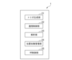
- FIG. 2 shows an example of the functional configuration of the network management device 1.
- the trigger generator 21 generates a trigger (trigger signal) for causing the terminal device 4 to make a pseudo emergency call.
- the trigger may include settings for making a pseudo emergency call multiple times, such as a period for making a pseudo emergency call and/or a setting for the number of times a pseudo emergency call is made. .
- the communication control unit 22 performs transmission processing and reception processing via the base station 3 .
- the communication control unit 22 performs transmission processing and reception processing for wireless data communication with the terminal device 4 .
- the analysis unit 23 analyzes the signal/call received from the terminal device 4 by the communication control unit 22 . For example, the analysis unit 23 determines whether the call originated from the terminal device 4 is a pseudo emergency call.
- the location collection management unit 24 performs control (signal generation and communication) for acquiring the location information of the terminal device 4 with the pseudo receiving device 2 .
- the call control unit 25 performs control for ending the call made by the terminal device 4 .
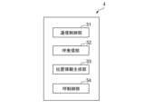
- FIG. 3 shows an example of the functional configuration of the terminal device 4.
- the communication control unit 31 performs transmission processing and reception processing.
- the communication control unit 31 performs transmission processing and reception processing for wireless data communication with the network management device 1 via the base station 3 .
- the call sending unit 32 makes a pseudo emergency call based on the trigger received from the network management device 1 by the communication control unit 31 .
- Call control can be performed according to a predetermined protocol such as SIP (Session Initiation Protocol).
- a call is sent in a signal consisting of a header portion and a body portion.
- the position information generation unit 33 performs positioning calculations based on signals received from GPS (Global Positioning System) satellites (not shown) and the like, and generates information obtained by the calculations as position information. In addition, the position information generation unit 33 returns a GPS acquisition error to the network management device 1 via the communication control unit 31 when the positioning function by GPS is not available. In response to this, the location collection management unit 24 of the network management device 1 can acquire location information (for example, latitude and longitude information) of the serving cell (cell 5 in FIG. 1) of the terminal device 4 . The call control unit 34 performs control for ending the call made by the terminal device 4 .
- GPS Global Positioning System
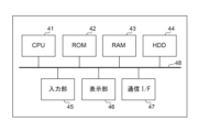
- FIG. 4 shows an example of the hardware configuration of the network management device 1 according to this embodiment.
- the network management device 1 according to this embodiment can be implemented on any computer, mobile device or any other processing platform, single or multiple.
- the multiple computers may be communicatively connected by a wired or wireless network.
- the network management device 1 includes a CPU 41, a ROM 42, a RAM 43, an HDD 44, an input section 45, a display section 46, a communication I/F (interface) 47, and a system bus 48. be prepared.
- the network management device 1 may also comprise an external memory (not shown).
- a CPU (Central Processing Unit) 41 comprehensively controls operations in the network management device 1, and controls each component (reference numbers 42 to 47) via a system bus 48, which is a data transmission line. .
- a ROM (Read Only Memory) 42 is a non-volatile memory that stores control programs necessary for the CPU 41 to execute processing, OS (Operating System) settings, and the like.
- the program may be stored in a non-volatile memory such as a HDD (Hard Disk Drive) 44 or an SSD (Solid State Drive) or an external memory such as a removable storage medium (not shown).
- the OS provides a basic program that provides an API (application interface) for controlling the hardware configuration shown in FIG.
- a RAM (Random Access Memory) 43 is a volatile memory and functions as a main memory, a work area, and the like for the CPU 41 . That is, the CPU 41 loads necessary programs and the like from the ROM 42 to the RAM 43 when executing processing, and executes the programs and the like to realize various functional operations.
- the HDD 44 stores, for example, various data and information necessary for the CPU 41 to perform processing using programs.
- the HDD 44 also stores various data and various information obtained by the CPU 41 performing processing using programs and the like, for example.
- the input unit 45 can be composed of a pointing device such as a keyboard and a mouse.
- the display unit 46 can be configured by a monitor such as a liquid crystal display (LCD).
- the display unit 46 may function as a GUI (Graphical User Interface) by being configured in combination with the input unit 45 .
- the communication I/F 47 is an interface that controls communication between the network management device 1 and external devices.
- a communication I/F 47 provides an interface with a network and executes communication with an external device via the network.
- Various data, various parameters, etc. are transmitted/received to/from an external device via the communication I/F 47 .
- the network may connect each device so as to be able to communicate with each other as long as communication is possible, and the communication standard, scale, and configuration are not limited to the above.
- At least some of the functions of the elements of the network management device 1 shown in FIG. 4 can be implemented by the CPU 41 executing a program. However, at least some of the functions of the elements of the network management device 1 shown in FIG. 4 may operate as dedicated hardware. In this case, the dedicated hardware operates under the control of the CPU 41 .
- the hardware configuration of the terminal device 4 can be the same configuration as the hardware configuration of the network management device 1 shown in FIG. That is, the terminal device 4 can include a CPU 41 , a ROM 42 , a RAM 43 , an HDD 44 , an input section 45 , a display section 46 , a communication I/F 47 and a system bus 48 . Since the function of each component is the same as described above, the description thereof will be omitted.
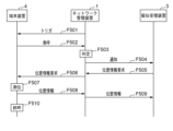
- FIG. 5 shows a sequence diagram of processing of the communication system according to this embodiment.
- the processing shown in FIG. 5 is performed when, for example, an inquiry from the police or the like searching for the user of the terminal device 4 is made to a telecommunications carrier (communication carrier) that manages the network management device 1, the telecommunications carrier It can be started when the called party number is specified and set in the network management device 1 .
- the called party number may be the number of the terminal device 4 (that is, one number), or the number that can communicate within the cell 5 in which the terminal device 4 is located (that is, that can be connected in a specific area). It may be the number of a plurality of terminal devices.
- the terminal device 4 has a predetermined application installed and activated.
- the application is associated with an application interface (API) provided by the OS, and the application allows the terminal device 4 to execute a series of processes via the API.
- API application interface
- the trigger generation unit 21 of the network management device 1 generates a trigger for making the terminal device 4 make a pseudo emergency call, and the communication control unit 22 transmits the set call destination number.
- the trigger may include the setting of the period and/or the number of times of making a pseudo emergency call as a setting for making a plurality of pseudo emergency calls.
- the transmission of the trigger may be performed by SMS (Short Message Service).
- the communication control unit 31 of the terminal device 4 receives the trigger transmitted at F501, and the call originating unit 32 makes a pseudo emergency call based on the trigger.
- the call originating unit 32 of the terminal device 4 can make a pseudo emergency call according to the period and/or number of times based on the settings included in the trigger.
- the terminal device 4 may make a call using an emergency telephone number (for example, 110, 119, and 118 in Japan) as a pseudo emergency call.
- an emergency telephone number for example, 110, 119, and 118 in Japan
- the call is a pseudo-emergency call, that is, it is not an emergency call spontaneously initiated by the terminal device 4, but an emergency call that is pseudo-emerged by a trigger from the network management device 1.
- the call may be made with information indicating that it is pseudonymous in the signals that make up the emergency call.
- the call originating unit 32 of the terminal device 4 can set (include) a flag indicating that the call is pseudo in the header of the signal that constitutes the emergency call.
- the terminal device 4 may make a call using a uniquely set number other than the above-described emergency call telephone number as a pseudo emergency call.
- the uniquely set number is known to a third party, there is a risk of unauthorized use of the number. It can be said that the security is higher when calling directly.
- the network management device 1 determines whether or not the call originated from the terminal device 4 in F502 is a simulated emergency call (F503). For example, when the analysis unit 23 of the network management device 1 confirms that a call has been made using the above-described emergency telephone number, it confirms whether or not there is a flag indicating that the call is pseudo. Then, when the flag is confirmed, the analysis unit 23 can determine that the call originated from the terminal device 4 is a simulated emergency call. Further, when the analysis unit 23 confirms that the call is made with the above-mentioned uniquely set number, the call originated from the terminal device 4 from the number is determined to be a simulated emergency call. can judge.
- F503 simulated emergency call
- the location collection management unit 24 of the network management device 1 sends the location information of the terminal device 4 to the pseudo receiving device 2.
- a predetermined notification is sent to the pseudo-receiving device 2 to cause it to send a requesting signal (positional information request).
- the predetermined notification may be identification information of the cell 5 in which the terminal device 4 is located, or information on an incoming call from the terminal device 4 .
- the pseudo-receiving device 2 receives the predetermined notification notified in F504, and in F505 transmits a location information request indicating a request to acquire the location information of the terminal device 4 to the network management device 1. 1 relays this and transmits it to the terminal device 4 (F506).
- the pseudo-receiving device 2 may transmit the location information request to the terminal device 4 multiple times. , it is possible to grasp the trajectory of the movement.
- the position information generation unit 33 performs positioning calculation in F507 to generate the position information of the terminal device 4.
- FIG. In F508 the communication control unit 31 of the terminal device 4 transmits the generated location information to the network management device 1, and the network management device 1 relays the location information to the pseudo receiving device 2 (F509).
- the call control unit 34 can terminate the call regardless of the setting of the trigger received in F501 (F510).
- the network management device 1 may control the end of the call.
- the pseudo receiving device 2 may transmit an acknowledgment (ACK) to the network management device 1 when it acquires the location information of the terminal device 4 .
- the call control unit 25 of the network management device 1 Upon receiving the ACK, the call control unit 25 of the network management device 1 transmits a signal for terminating the call to the terminal device 4.
- the communication control unit 31 transmits the signal is received and the call control unit 34 can terminate the call.
- the position information generation unit 33 sends the GPS acquisition error to the network management device 1 via the communication control unit 31 as described above. return.
- the location collection management unit 24 of the network management device 1 acquires location information (for example, latitude and longitude information) of the serving cell (cell 5 in FIG. 1) of the terminal device 4, and stores the location information. Send to the pseudo-receiving device 3 .
- the processing of F503 to F505 and F509 can be executed by the communication device 6. Therefore, in this case, when the communication device 6 determines that the received call is a simulated emergency call (F503), it transmits a location information request to the terminal device 4 and acquires location information from the terminal device 4. (F508).
- the terminal device even if the user of the terminal device cannot operate the terminal device in an emergency/emergency such as a disaster, the terminal device receives an emergency call by a trigger from the network management device. can call As a result, the host management device can efficiently acquire the location information of the terminal device, which narrows the search range for disaster relief activities and helps rescue the user.
Landscapes
- Engineering & Computer Science (AREA)
- Signal Processing (AREA)
- Telephonic Communication Services (AREA)
Abstract
ネットワーク管理装置(1)は、端末装置に緊急呼を擬似的に発呼させるためのトリガを生成し、当該トリガを前記端末装置へ送信し、当該トリガの送信の後に当該端末装置から発呼された呼が擬似的な緊急呼であるか否かを判定し、当該呼が当該擬似的な緊急呼であると判定された場合に、当該端末装置の位置情報を取得するための要求を、当該端末装置に送信する。
Description
本発明は、緊急時における端末装置の位置情報を取得するための技術に関する。
電気通信事業者としての通信キャリアが緊急通報(例えば、日本では110番、118番、119番)を扱う際に、管轄の緊急通報受理機関(PSAP(Public Safety Answering Point))に接続し、発信者の位置情報を通知するシステムが存在する。
このようなシステムを無線通信に適用する場合に、端末装置から緊急通報が発信されたことを受けて緊急通報受理機関が当該端末装置に位置情報送信要求を行い、これに応じて、当該端末装置が、当該端末装置の位置情報を当該緊急通報受理機関に送信する仕組みが利用されている(特許文献1)。
このようなシステムを無線通信に適用する場合に、端末装置から緊急通報が発信されたことを受けて緊急通報受理機関が当該端末装置に位置情報送信要求を行い、これに応じて、当該端末装置が、当該端末装置の位置情報を当該緊急通報受理機関に送信する仕組みが利用されている(特許文献1)。
前述のような従来の仕組みでは、端末装置の位置情報取得のために当該端末装置による発信が前提となっているため、緊急時における位置情報の取得が困難な場合があった。例えば、被災等により通報者が端末装置を操作できない状況下では、端末装置からの発信が不可能であり、これにより、受信機関は位置情報送信要求を行うことができない。このような場合には、緊急時にも関わらず、緊急応答機関では当該端末装置の位置情報を取得することができなかった。
本発明は上記課題に鑑みてなされたものであり、端末装置の状況にかかわらず、緊急時における端末装置の位置情報を効率的に取得するための技術を提供することを目的とする。
上記課題を解決するために、本発明によるネットワーク管理装置の一態様は、端末装置に緊急呼を擬似的に発呼させるためのトリガを生成する生成部と、前記トリガを前記端末装置へ送信する第1の送信部と、前記トリガの送信の後に前記端末装置から発呼された呼が擬似的な緊急呼であるか否かを判定する判定部と、前記判定部により前記呼が前記擬似的な緊急呼であると判定された場合に、前記端末装置の位置情報を取得するための要求を、前記端末装置に送信する第2の送信部と、を有する。
上記課題を解決するために、本発明によるネットワーク管理装置の別の態様は、端末装置に緊急呼を擬似的に発呼させるためのトリガを生成する生成部と、前記トリガを前記端末装置へ送信する第1の送信部と、前記トリガの送信の後に前記端末装置から発呼された呼が擬似的な緊急呼であるか否かを判定する判定部と、前記判定部により前記呼が前記擬似的な緊急呼であると判定された場合に、前記端末装置の位置情報を取得するための要求を他の装置から前記端末装置に送信させるための通知を前記他の装置へ送信する第2の送信部と、を有する。
前記ネットワーク管理装置は、前記第2の送信部により前記通知が前記他の装置へ送信されたことに応じて前記他の装置から受信された前記要求を前記端末装置へ中継する中継部をさらに有しうる。
前記ネットワーク管理装置において、前記生成部は、前記緊急呼を擬似的に複数回発呼させるための設定を、前記トリガに含めうる。
前記ネットワーク管理装置において、前記設定は、発呼の周期と発呼の回数の少なくとも一方を含みうる。
前記ネットワーク管理装置は、前記要求が前記端末装置に送信されたことに応じて前記端末装置から送信される前記端末装置の位置情報を複数回収集する収集部をさらに有しうる。
前記ネットワーク管理装置は、前記収集部により前記位置情報が少なくとも1回収集された場合に、前記端末装置による発呼を終了させる呼制御部をさらに有しうる。
前記ネットワーク管理装置において、前記判定部は、前記呼が緊急通報用電話番号で発呼された呼である場合に、前記呼は前記擬似的な緊急呼であると判定しうる。
前記ネットワーク管理装置において、前記判定部は、前記呼を構成する信号に、擬似的な緊急呼であることを示す情報が含まれる場合に、前記呼は前記擬似的な緊急呼であると判定しうる。
前記ネットワーク管理装置において、前記判定部は、前記呼が固有に設定された番号で発呼された呼である場合に、前記呼は前記擬似的な緊急呼であると判定しうる。
上記課題を解決するために、本発明による端末装置の一態様は、他の装置から、緊急呼を擬似的に発呼するためのトリガを受信する第1の受信部と、前記トリガに基づいて発呼する発呼部と、前記発呼部による発呼の後に、前記他の装置から前記端末装置の位置情報を取得するための要求を受信する第2の受信部と、前記第2の受信部による前記要求の受信に応じて、前記端末装置の位置情報を取得する取得部と、前記取得部より取得された前記位置情報を前記他の装置へ送信する送信部と、を有する。
前記端末装置において、前記発呼部は、緊急通報用電話番号で発呼しうる。
また、前記端末装置において、前記発呼部は、呼を構成する信号に、擬似的な緊急呼であることを示す情報を含めて発呼しうる。
また、前記端末装置において、前記発呼部は、呼を構成する信号に、擬似的な緊急呼であることを示す情報を含めて発呼しうる。
前記端末装置は、前記送信部により前記位置情報が前記他の装置へ送信された場合に、前記発呼部による発呼を終了させる呼制御部をさらに有しうる。
上記課題を解決するために、本発明によるネットワーク管理方法の一態様は、端末装置に緊急呼を擬似的に発呼させるためのトリガを生成する生成工程と、前記トリガを前記端末装置へ送信する第1の送信工程と、前記トリガの送信の後に前記端末装置から発呼された呼が擬似的な緊急呼であるか否かを判定する判定工程と、前記判定工程において前記呼が前記擬似的な緊急呼であると判定された場合に、前記端末装置の位置情報を取得するための要求を、前記端末装置に送信する第2の送信工程と、を有する。
上記課題を解決するために、本発明によるネットワーク管理方法の別の態様は、端末装置に緊急呼を擬似的に発呼させるためのトリガを生成する生成工程と、前記トリガを前記端末装置へ送信する第1の送信工程と、前記トリガの送信の後に前記端末装置から発呼された呼が擬似的な緊急呼であるか否かを判定する判定工程と、前記判定工程において前記呼が前記擬似的な緊急呼であると判定された場合に、前記端末装置の位置情報を取得するための要求を他の装置から前記端末装置に送信させるための通知を前記他の装置へ送信する第2の送信工程と、を有する。
上記課題を解決するために、本発明による情報処理プログラムの一態様は、情報処理をコンピュータに実行させるための情報処理プログラムであって、該プログラムは、前記コンピュータに、他の装置から、緊急呼を擬似的に発呼するためのトリガを受信する第1の受信処理と、前記トリガに基づいて発呼する発呼処理と、前記発呼部による発呼の後に、前記他の装置から前記端末装置の位置情報を取得するための要求を受信する第2の受信処理と、前記第2の受信部による前記要求の受信に応じて、前記端末装置の位置情報を取得する取得処理と、前記取得部より取得された前記位置情報を前記他の装置へ送信する送信処理と、を含む処理を実行させるためのものである。
上記課題を解決するために、本発明による通信システムの一態様は、ネットワーク管理装置と端末装置を有する通信システムであって、前記ネットワーク管理装置は、前記端末装置に緊急呼を擬似的に発呼させるためのトリガを生成する生成部と、前記トリガを前記端末装置へ送信する第1の送信部と、前記トリガの送信の後に前記端末装置から発呼された呼が擬似的な緊急呼であるか否かを判定する判定部と、前記判定部により前記呼が前記擬似的な緊急呼であると判定された場合に、前記端末装置の位置情報を取得するための要求を、前記端末装置に送信する第2の送信部と、を有し、前記端末装置は、前記ネットワーク管理装置から、前記トリガを受信する第1の受信部と、前記トリガに基づいて発呼する発呼部と、前記ネットワーク管理装置から前記要求を受信する第2の受信部と、前記第2の受信部による前記要求の受信に応じて、前記端末装置の位置情報を取得する取得部と、前記取得部より取得された前記位置情報を前記ネットワーク管理装置へ送信する第3の送信部と、を有する。
上記課題を解決するために、本発明による通信システムの別の態様は、ネットワーク管理装置と端末装置を有する通信システムであって、前記ネットワーク管理装置は、前記端末装置に緊急呼を擬似的に発呼させるためのトリガを生成する生成部と、前記トリガを前記端末装置へ送信する第1の送信部と、前記トリガの送信の後に前記端末装置から発呼された呼が擬似的な緊急呼であるか否かを判定する判定部と、前記判定部により前記呼が前記擬似的な緊急呼であると判定された場合に、前記端末装置の位置情報を取得するための要求を他の装置から前記端末装置に送信させるための通知を前記他の装置へ送信する第2の送信部と、を有し、前記端末装置は、前記ネットワーク管理装置から、前記トリガを受信する第1の受信部と、前記トリガに基づいて発呼する発呼部と、前記発呼部による発呼の後に、前記他の装置から前記端末装置の位置情報を取得するための要求を受信する第2の受信部と、前記第2の受信部による前記要求の受信に応じて、前記端末装置の位置情報を取得する取得部と、前記取得部より取得された前記位置情報を前記ネットワーク管理装置へ送信する第3の送信部と、を有する。
本発明によれば、端末装置の状況にかかわらず、緊急時における端末装置の位置情報を効率的に取得することが可能となる。
上記した本発明の目的、態様及び効果並びに上記されなかった本発明の目的、態様及び効果は、当業者であれば添付図面及び請求の範囲の記載を参照することにより下記の発明を実施するための形態から理解できるであろう。
上記した本発明の目的、態様及び効果並びに上記されなかった本発明の目的、態様及び効果は、当業者であれば添付図面及び請求の範囲の記載を参照することにより下記の発明を実施するための形態から理解できるであろう。
前述のように、従来では、端末装置が発信する緊急通報(以下、緊急呼と称する)を、緊急通報受理機関が受信し、当該機関が位置情報送信要求を端末装置に通知し、これに応じて、端末装置は当該端末装置の位置情報を測定して、当該機関に通知していた。
本実施形態では、端末装置のユーザが、被災等により当該端末装置を操作できないといった、端末装置からの発信が不可能である場合であっても、当該端末装置が接続するネットワークを管理する管理サーバが、当該端末装置が緊急呼を発信できるように制御する。また、本実施形態では、端末装置により擬似的に発呼された緊急呼に応じて、当該端末装置の位置情報を要求するための位置情報要求を送信する、擬似的な緊急応答受理機関を設ける。
(通信システムの構成)
本実施形態による通信システムの構成例を図1に示す。当該通信システムは、図1に示すように、ネットワーク管理装置1、擬似受理装置2、基地局3、および端末装置4から構成される。ネットワーク管理装置1は、端末装置4が接続するネットワークを管理する管理サーバであり、基地局3を介して端末装置4と通信可能に構成される。擬似受理装置2は、緊急通報受理機関(PSAP(Public Safety Answering Point))の役割を模した、擬似的な緊急通報応答機関である。ネットワーク管理装置1と擬似受理装置2は、互いに通信可能に構成されている。なお、ネットワーク管理装置1と擬似受理装置2は、論理的に別個の装置であればよく、物理的に1つの通信装置(構成要素)6であってもよい。
本実施形態による通信システムの構成例を図1に示す。当該通信システムは、図1に示すように、ネットワーク管理装置1、擬似受理装置2、基地局3、および端末装置4から構成される。ネットワーク管理装置1は、端末装置4が接続するネットワークを管理する管理サーバであり、基地局3を介して端末装置4と通信可能に構成される。擬似受理装置2は、緊急通報受理機関(PSAP(Public Safety Answering Point))の役割を模した、擬似的な緊急通報応答機関である。ネットワーク管理装置1と擬似受理装置2は、互いに通信可能に構成されている。なお、ネットワーク管理装置1と擬似受理装置2は、論理的に別個の装置であればよく、物理的に1つの通信装置(構成要素)6であってもよい。
端末装置4は、ネットワーク管理装置1により管理される基地局3と無線接続可能な位置(例えば基地局3により形成されるセル5内)に位置する装置である。なお、図1では、セル5内に1つの端末装置4が示されているが、セル内5に存在する、端末装置4と同様の機能を有する1つ以上の他の端末装置が存在してもよい。端末装置4は、例えば、携帯電話、スマートデバイス(スマートフォンやタブレット)、PDA(Personal Digital Assistant)、ウェアラブル端末でありうる。
本実施形態において、ネットワーク管理装置1は、端末装置4に擬似的に緊急呼を発呼させるためのトリガを生成し、基地局3を介して端末装置4へ送信し、当該トリガ送信後に端末装置4から発呼された呼が擬似的な緊急呼であるか否かを判定する。そして、当該呼が擬似的な緊急呼であると判定された場合に、ネットワーク管理装置1は、端末装置4の位置情報を取得するよう制御する。当該制御は、ネットワーク管理装置1が、当該位置情報を取得するための通知を擬似受理装置2から端末装置4に送信することを含み、この場合、擬似受理装置3は当該通知の受信に応じて、当該位置情報を要求するための信号をネットワーク管理装置1へ送信し、ネットワーク管理装置1はこれを端末装置4へ中継する。また、ネットワーク管理装置1と擬似受理装置2が1つの通信装置6で構成される場合は、当該制御は、通信装置6が、当該位置情報を要求するための信号を端末装置4へ送信することを含む。
[ネットワーク管理装置1の機能構成]
図2に、ネットワーク管理装置1の機能構成の一例を示す。
トリガ生成部21は、端末装置4に擬似的に緊急呼を発呼させるためのトリガ(トリガ信号)を生成する。当該トリガには、擬似的に緊急呼を複数回発呼させるための設定として、擬似的に緊急呼を発呼させる周期および/または擬似的に緊急呼を発呼させる回数の設定が含まれうる。
図2に、ネットワーク管理装置1の機能構成の一例を示す。
トリガ生成部21は、端末装置4に擬似的に緊急呼を発呼させるためのトリガ(トリガ信号)を生成する。当該トリガには、擬似的に緊急呼を複数回発呼させるための設定として、擬似的に緊急呼を発呼させる周期および/または擬似的に緊急呼を発呼させる回数の設定が含まれうる。
通信制御部22は、基地局3を介した送信処理や受信処理を行う。本実施形態では、通信制御部22は、端末装置4との間の無線データ通信のための送信処理や受信処理を行う。
解析部23は、通信制御部22により端末装置4から受信された信号/呼の解析を行う。例えば、解析部23は、端末装置4から発呼された呼が擬似的な緊急呼であるか否かを判定する。
解析部23は、通信制御部22により端末装置4から受信された信号/呼の解析を行う。例えば、解析部23は、端末装置4から発呼された呼が擬似的な緊急呼であるか否かを判定する。
位置収集管理部24は、擬似受理装置2との間で、端末装置4の位置情報を取得するための制御(信号の生成や通信)を行う。
呼制御部25は、端末装置4による発呼を終了させるための制御を行う。
呼制御部25は、端末装置4による発呼を終了させるための制御を行う。
[端末装置4の機能構成]
図3に、端末装置4の機能構成の一例を示す。
通信制御部31は、送信処理や受信処理を行う。本実施形態では、通信制御部31は、基地局3を介してネットワーク管理装置1との間の無線データ通信のための送信処理や受信処理を行う。
呼発信部32は、通信制御部31によりネットワーク管理装置1から受信されたトリガに基づいて、擬似的に緊急呼を発呼する。呼制御は、例えば、SIP(Session Initiation Protocol)といった所定のプロトコルに従って行われうる。呼は、ヘッダ部とボディ部を有する構成の信号で送信される。
図3に、端末装置4の機能構成の一例を示す。
通信制御部31は、送信処理や受信処理を行う。本実施形態では、通信制御部31は、基地局3を介してネットワーク管理装置1との間の無線データ通信のための送信処理や受信処理を行う。
呼発信部32は、通信制御部31によりネットワーク管理装置1から受信されたトリガに基づいて、擬似的に緊急呼を発呼する。呼制御は、例えば、SIP(Session Initiation Protocol)といった所定のプロトコルに従って行われうる。呼は、ヘッダ部とボディ部を有する構成の信号で送信される。
位置情報生成部33は、GPS(Global Positioning System)衛星(不図示)から受信される信号等に基づいて測位計算を行い、当該計算により得られた情報を位置情報として生成する。なお、位置情報生成部33は、GPSによる測位機能が利用可能でない場合、通信制御部31を介して、GPS取得エラーをネットワーク管理装置1へ返す。これに応じて、ネットワーク管理装置1の位置収集管理部24は、端末装置4の在圏セル(図1の場合はセル5)の位置情報(例えば緯度経度情報)を取得することができる。
呼制御部34は、端末装置4による発呼を終了させるための制御を行う。
呼制御部34は、端末装置4による発呼を終了させるための制御を行う。
[ネットワーク管理装置1のハードウェア構成]
図4は、本実施形態によるネットワーク管理装置1のハードウェア構成の一例を示す。
本実施形態によるネットワーク管理装置1は、単一または複数の、あらゆるコンピュータ、モバイルデバイス、または他のいかなる処理プラットフォーム上にも実装することができる。複数のコンピュータで実装される場合、当該複数のコンピュータは、有線または無線のネットワークにより相互通信可能に接続されてよい。
図4は、本実施形態によるネットワーク管理装置1のハードウェア構成の一例を示す。
本実施形態によるネットワーク管理装置1は、単一または複数の、あらゆるコンピュータ、モバイルデバイス、または他のいかなる処理プラットフォーム上にも実装することができる。複数のコンピュータで実装される場合、当該複数のコンピュータは、有線または無線のネットワークにより相互通信可能に接続されてよい。
図4に示すように、ネットワーク管理装置1は、CPU41と、ROM42と、RAM43と、HDD44と、入力部45と、表示部46と、通信I/F(インタフェース)47と、システムバス48とを備えうる。ネットワーク管理装置1はまた、外部メモリ(不図示)を備えてよい。
CPU(Central Processing Unit)41は、ネットワーク管理装置1における動作を統括的に制御するものであり、データ伝送路であるシステムバス48を介して、各構成部(参照番号42~47)を制御する。
CPU(Central Processing Unit)41は、ネットワーク管理装置1における動作を統括的に制御するものであり、データ伝送路であるシステムバス48を介して、各構成部(参照番号42~47)を制御する。
ROM(Read Only Memory)42は、CPU41が処理を実行するために必要な制御プログラムやOS(Operating System)の設定等を記憶する不揮発性メモリである。当該プログラムは、HDD(Hard Disk Drive)44、SSD(Solid State Drive)等の不揮発性メモリや着脱可能な記憶媒体(不図示)等の外部メモリに記憶されていてもよい。OSは、図4に示すハードウェア構成を制御するためのAPI(アプリケーションインタフェース)を提供する基本プログラムを提供する。
RAM(Random Access Memory)43は、揮発性メモリであり、CPU41の主メモリ、ワークエリア等として機能する。すなわち、CPU41は、処理の実行に際してROM42から必要なプログラム等をRAM43にロードし、当該プログラム等を実行することで各種の機能動作を実現する。
RAM(Random Access Memory)43は、揮発性メモリであり、CPU41の主メモリ、ワークエリア等として機能する。すなわち、CPU41は、処理の実行に際してROM42から必要なプログラム等をRAM43にロードし、当該プログラム等を実行することで各種の機能動作を実現する。
HDD44は、例えば、CPU41がプログラムを用いた処理を行う際に必要な各種データや各種情報等を記憶している。また、HDD44には、例えば、CPU41がプログラム等を用いた処理を行うことにより得られた各種データや各種情報等が記憶される。
入力部45は、キーボードやマウス等のポインティングデバイスにより構成されうる。
表示部46は、液晶ディスプレイ(LCD)等のモニターにより構成されうる。表示部46は、入力部45と組み合わせて構成されることにより、GUI(Graphical User Interface)として機能してもよい。
入力部45は、キーボードやマウス等のポインティングデバイスにより構成されうる。
表示部46は、液晶ディスプレイ(LCD)等のモニターにより構成されうる。表示部46は、入力部45と組み合わせて構成されることにより、GUI(Graphical User Interface)として機能してもよい。
通信I/F47は、ネットワーク管理装置1と外部装置との通信を制御するインタフェースである。
通信I/F47は、ネットワークとのインタフェースを提供し、ネットワークを介して、外部装置との通信を実行する。通信I/F47を介して、外部装置との間で各種データや各種パラメータ等が送受信される。なお、当該ネットワークは、各機器を相互に通信可能に接続し、通信が可能であればよく、通信の規格、規模、構成は上記に限定されない。
通信I/F47は、ネットワークとのインタフェースを提供し、ネットワークを介して、外部装置との通信を実行する。通信I/F47を介して、外部装置との間で各種データや各種パラメータ等が送受信される。なお、当該ネットワークは、各機器を相互に通信可能に接続し、通信が可能であればよく、通信の規格、規模、構成は上記に限定されない。
図4に示すネットワーク管理装置1の各要素のうち少なくとも一部の機能は、CPU41がプログラムを実行することで実現することができる。ただし、図4に示すネットワーク管理装置1の各要素のうち少なくとも一部の機能が専用のハードウェアとして動作するようにしてもよい。この場合、専用のハードウェアは、CPU41の制御に基づいて動作する。
[端末装置4のハードウェア構成]
端末装置4のハードウェア構成は、図4に示したネットワーク管理装置1のハードウェア構成と同様の構成でありうる。すなわち、端末装置4は、CPU41と、ROM42と、RAM43と、HDD44と、入力部45と、表示部46と、通信I/F47と、システムバス48とを備えうる。各構成部の機能は、上記と同様のため、その説明を省略する。
端末装置4のハードウェア構成は、図4に示したネットワーク管理装置1のハードウェア構成と同様の構成でありうる。すなわち、端末装置4は、CPU41と、ROM42と、RAM43と、HDD44と、入力部45と、表示部46と、通信I/F47と、システムバス48とを備えうる。各構成部の機能は、上記と同様のため、その説明を省略する。
[処理の流れ]
図5に、本実施形態による通信システムの処理のシーケンス図を示す。図5に示す処理は、例えば、端末装置4のユーザを捜索する警察等からの照会が、ネットワーク管理装置1を管理する通信事業者(通信キャリア)に行われた場合に、当該通信事業者が発呼先番号を特定してネットワーク管理装置1に設定したことを受けて開始されうる。なお、発呼先番号は、端末装置4の番号(すなわち1つの番号)であってもよいし、端末装置4が位置するセル5内で通信可能な(すなわち、特定の地域で接続可能な)複数の端末装置の番号であってもよい。また、端末装置4は、所定のアプリケーションがインストールされ、起動されているものとする。当該アプリケーションは、OSが提供するアプリケーションインタフェース(API)と関連付けられており、当該アプリケーションにより、APIを介して端末装置4による一連の処理が実行されうる。
図5に、本実施形態による通信システムの処理のシーケンス図を示す。図5に示す処理は、例えば、端末装置4のユーザを捜索する警察等からの照会が、ネットワーク管理装置1を管理する通信事業者(通信キャリア)に行われた場合に、当該通信事業者が発呼先番号を特定してネットワーク管理装置1に設定したことを受けて開始されうる。なお、発呼先番号は、端末装置4の番号(すなわち1つの番号)であってもよいし、端末装置4が位置するセル5内で通信可能な(すなわち、特定の地域で接続可能な)複数の端末装置の番号であってもよい。また、端末装置4は、所定のアプリケーションがインストールされ、起動されているものとする。当該アプリケーションは、OSが提供するアプリケーションインタフェース(API)と関連付けられており、当該アプリケーションにより、APIを介して端末装置4による一連の処理が実行されうる。
F501において、ネットワーク管理装置1のトリガ生成部21は、端末装置4に擬似的に緊急呼を発呼させるためのトリガを生成し、通信制御部22は、設定された発呼先番号で送信する。前述のように、当該トリガには、擬似的に緊急呼を複数回発呼させるための設定として、擬似的に緊急呼を発呼させる周期および/または回数の設定が含まれうる。当該トリガの送信は、SMS(ショートメッセージサービス)により行われてもよい。
F502において、端末装置4の通信制御部31は、F501で送信されたトリガを受信し、呼発信部32は、当該トリガに基づいて擬似的に緊急呼を発呼する。ここで、端末装置4の呼発信部32は、トリガに含まれる設定に基づく周期および/または回数に従って、擬似的に緊急呼を発呼することができる。
端末装置4は、擬似的な緊急呼として、緊急通報用電話番号(例えば、日本では110番、119番、118番)で発呼してもよい。この場合、擬似的な緊急呼であること、すなわち、端末装置4から自発的に発呼される緊急呼ではなく、ネットワーク管理装置1からのトリガにより擬似的に発呼する緊急呼であることを明確に示すために、緊急呼を構成する信号に、擬似的であることを示す情報を含めて、発呼してもよい。例えば、端末装置4の呼発信部32は、緊急呼を構成する信号のヘッダ部に、擬似的であることを示すフラグを立てて(含めて)発呼することができる。
あるいは、端末装置4は、擬似的な緊急呼として、前述の緊急通報用電話番号以外の固有に設定された番号で発呼してもよい。ただし、当該固有に設定された番号が第三者に知られると当該番号が不正に利用される恐れがあり、このようななりすましを防止するために、前述の緊急通報用電話番号を用いて擬似的に発呼する方が、セキュリティが高いといえる。
あるいは、端末装置4は、擬似的な緊急呼として、前述の緊急通報用電話番号以外の固有に設定された番号で発呼してもよい。ただし、当該固有に設定された番号が第三者に知られると当該番号が不正に利用される恐れがあり、このようななりすましを防止するために、前述の緊急通報用電話番号を用いて擬似的に発呼する方が、セキュリティが高いといえる。
ネットワーク管理装置1は、F502で端末装置4から発信された呼が擬似的に発呼された緊急呼であるか否かを判定する(F503)。
例えば、ネットワーク管理装置1の解析部23は、前述の緊急通報用電話番号での発呼を確認した場合は、当該呼が擬似的であることを示すフラグの有無を確認する。そして、当該フラグが確認されると、解析部23は、端末装置4から発信された呼が擬似的に発呼された緊急呼であると判定することができる。
また、解析部23は、前述の固有に設定された番号での発呼を確認した場合は、当該番号から、端末装置4から発信された呼が擬似的に発呼された緊急呼であると判定することができる。
例えば、ネットワーク管理装置1の解析部23は、前述の緊急通報用電話番号での発呼を確認した場合は、当該呼が擬似的であることを示すフラグの有無を確認する。そして、当該フラグが確認されると、解析部23は、端末装置4から発信された呼が擬似的に発呼された緊急呼であると判定することができる。
また、解析部23は、前述の固有に設定された番号での発呼を確認した場合は、当該番号から、端末装置4から発信された呼が擬似的に発呼された緊急呼であると判定することができる。
F503において、受信した呼が擬似的に発呼された緊急呼であると判定すると、F504において、ネットワーク管理装置1の位置収集管理部24は、擬似受理装置2に、端末装置4の位置情報を要求するための信号(位置情報要求)を送信させるための所定の通知を擬似受理装置2に送信する。当該所定の通知は、端末装置4が位置するセル5の識別情報や、端末装置4からの着呼の情報でありうる。
擬似受理装置2は、F504で通知された所定の通知を受信し、F505において、端末装置4の位置情報を取得するための要求を示す位置情報要求をネットワーク管理装置1に送信し、ネットワーク管理装置1はこれを中継し端末装置4に送信する(F506)。擬似受理装置2は位置情報要求を複数回端末装置4に送信してもよく、その場合、端末装置4による位置情報が複数回取得(収集)できることから、端末装置4が移動している場合は、その移動の軌跡を把握することが可能となる。
端末装置4の通信制御部31がF506で送信された位置情報要求を受信すると、位置情報生成部33は、F507において測位計算を行い、端末装置4の位置情報を生成する。
F508において、端末装置4の通信制御部31は、生成した位置情報をネットワーク管理装置1へ送信し、ネットワーク管理装置1は当該位置情報を擬似受理装置2へ中継する(F509)。
F508において、端末装置4の通信制御部31は、生成した位置情報をネットワーク管理装置1へ送信し、ネットワーク管理装置1は当該位置情報を擬似受理装置2へ中継する(F509)。
端末装置4の通信制御部31がF508で位置情報を送信すると、F501で受信したトリガにおける設定にかかわらず、呼制御部34は、呼を終了させることができる(F510)。なお、呼の終了はネットワーク管理装置1が制御してもよい。例えば、擬似受理装置2は端末装置4の位置情報を取得した場合に、ネットワーク管理装置1に対して確認応答(ACK)を送信してもよい。そして、ネットワーク管理装置1の呼制御部25は、当該ACKを受信したことを受けて、呼を終了させるための信号を端末装置4に送信し、端末装置4では、通信制御部31が当該信号を受信し、呼制御部34が呼を終了させることができる。
なお、F507において、位置情報生成部33がGPSによる測位機能が利用可能でない場合、前述のように、位置情報生成部33は、通信制御部31を介して、GPS取得エラーをネットワーク管理装置1へ返す。これに応じて、ネットワーク管理装置1の位置収集管理部24は、端末装置4の在圏セル(図1の場合はセル5)の位置情報(例えば緯度経度情報)を取得し、当該位置情報を擬似受理装置3へ送信する。
また、ネットワーク管理装置1と擬似受理装置2が1つの通信装置6で構成される場合は、F503~F505、F509の処理は通信装置6により実行されうる。よってこの場合、通信装置6は、受信した呼が擬似的に発呼された緊急呼であると判定すると(F503)、位置情報要求を端末装置4に送信し、端末装置4から位置情報を取得することになる(F508)。
このように、本実施形態によれば、端末装置のユーザが災害等の緊急/非常時に、当該端末装置の操作ができない場合であっても、ネットワーク管理装置からのトリガにより当該端末装置は緊急呼を発呼できる。これにより、上位の管理装置側では当該端末装置の位置情報を効率的に取得できるため、災害救助活動の捜索範囲が狭まり、当該ユーザの救助に役立つ。
なお、上記において特定の実施形態が説明されているが、当該実施形態は単なる例示であり、本発明の範囲を限定する意図はない。本明細書に記載された装置及び方法は上記した以外の形態において具現化することができる。また、本発明の範囲から離れることなく、上記した実施形態に対して適宜、省略、置換及び変更をなすこともできる。かかる省略、置換及び変更をなした形態は、請求の範囲に記載されたもの及びこれらの均等物の範疇に含まれ、本発明の技術的範囲に属する。
1:ネットワーク管理装置、2:擬似受理装置、3:基地局、4:端末装置、5:セル、6:通信装置
Claims (19)
- 端末装置に緊急呼を擬似的に発呼させるためのトリガを生成する生成部と、
前記トリガを前記端末装置へ送信する第1の送信部と、
前記トリガの送信の後に前記端末装置から発呼された呼が擬似的な緊急呼であるか否かを判定する判定部と、
前記判定部により前記呼が前記擬似的な緊急呼であると判定された場合に、前記端末装置の位置情報を取得するための要求を、前記端末装置に送信する第2の送信部と、
を有することを特徴とするネットワーク管理装置。 - 端末装置に緊急呼を擬似的に発呼させるためのトリガを生成する生成部と、
前記トリガを前記端末装置へ送信する第1の送信部と、
前記トリガの送信の後に前記端末装置から発呼された呼が擬似的な緊急呼であるか否かを判定する判定部と、
前記判定部により前記呼が前記擬似的な緊急呼であると判定された場合に、前記端末装置の位置情報を取得するための要求を他の装置から前記端末装置に送信させるための通知を前記他の装置へ送信する第2の送信部と、
を有することを特徴とするネットワーク管理装置。 - 前記第2の送信部により前記通知が前記他の装置へ送信されたことに応じて前記他の装置から受信された前記要求を前記端末装置へ中継する中継部をさらに有することを特徴とする請求項2に記載のネットワーク管理装置。
- 前記生成部は、前記緊急呼を擬似的に複数回発呼させるための設定を、前記トリガに含めることを特徴とする請求項1から3のいずれか1項に記載のネットワーク管理装置。
- 前記設定は、発呼の周期と発呼の回数の少なくとも一方を含むことを特徴とする請求項4に記載のネットワーク管理装置。
- 前記要求が前記端末装置に送信されたことに応じて前記端末装置から送信される前記端末装置の位置情報を複数回収集する収集部をさらに有することを特徴とする請求項1から5のいずれか1項に記載のネットワーク管理装置。
- 前記収集部により前記位置情報が少なくとも1回収集された場合に、前記端末装置による発呼を終了させる呼制御部をさらに有することを特徴とする請求項6に記載のネットワーク管理装置。
- 前記判定部は、前記呼が緊急通報用電話番号で発呼された呼である場合に、前記呼は前記擬似的な緊急呼であると判定することを特徴とする請求項1から7のいずれか1項に記載のネットワーク管理装置。
- 前記判定部は、前記呼を構成する信号に、擬似的な緊急呼であることを示す情報が含まれる場合に、前記呼は前記擬似的な緊急呼であると判定することを特徴とする請求項8に記載のネットワーク管理装置。
- 前記判定部は、前記呼が固有に設定された番号で発呼された呼である場合に、前記呼は前記擬似的な緊急呼であると判定することを特徴とする請求項1から7のいずれか1項に記載のネットワーク管理装置。
- 他の装置から、緊急呼を擬似的に発呼するためのトリガを受信する第1の受信部と、
前記トリガに基づいて発呼する発呼部と、
前記発呼部による発呼の後に、前記他の装置から前記端末装置の位置情報を取得するための要求を受信する第2の受信部と、
前記第2の受信部による前記要求の受信に応じて、前記端末装置の位置情報を取得する取得部と、
前記取得部より取得された前記位置情報を前記他の装置へ送信する送信部と、
を有することを特徴とする端末装置。 - 前記発呼部は、緊急通報用電話番号で発呼することを特徴とする請求項11に記載の端末装置。
- 前記発呼部は、呼を構成する信号に、擬似的な緊急呼であることを示す情報を含めて発呼することを特徴とする請求項12に記載の端末装置。
- 前記送信部により前記位置情報が前記他の装置へ送信された場合に、前記発呼部による発呼を終了させる呼制御部をさらに有することを特徴とする請求項11から13のいずれか1項に記載の端末装置。
- 端末装置に緊急呼を擬似的に発呼させるためのトリガを生成する生成工程と、
前記トリガを前記端末装置へ送信する第1の送信工程と、
前記トリガの送信の後に前記端末装置から発呼された呼が擬似的な緊急呼であるか否かを判定する判定工程と、
前記判定工程において前記呼が前記擬似的な緊急呼であると判定された場合に、前記端末装置の位置情報を取得するための要求を、前記端末装置に送信する第2の送信工程と、
を有することを特徴とするネットワーク管理方法。 - 端末装置に緊急呼を擬似的に発呼させるためのトリガを生成する生成工程と、
前記トリガを前記端末装置へ送信する第1の送信工程と、
前記トリガの送信の後に前記端末装置から発呼された呼が擬似的な緊急呼であるか否かを判定する判定工程と、
前記判定工程において前記呼が前記擬似的な緊急呼であると判定された場合に、前記端末装置の位置情報を取得するための要求を他の装置から前記端末装置に送信させるための通知を前記他の装置へ送信する第2の送信工程と、
を有することを特徴とするネットワーク管理方法。 - 情報処理をコンピュータに実行させるための情報処理プログラムであって、該プログラムは、前記コンピュータに、
他の装置から、緊急呼を擬似的に発呼するためのトリガを受信する第1の受信処理と、
前記トリガに基づいて発呼する発呼処理と、
前記発呼部による発呼の後に、前記他の装置から前記端末装置の位置情報を取得するための要求を受信する第2の受信処理と、
前記第2の受信部による前記要求の受信に応じて、前記端末装置の位置情報を取得する取得処理と、
前記取得部より取得された前記位置情報を前記他の装置へ送信する送信処理と、を含む処理を実行させるためのものである、
情報処理プログラム。 - ネットワーク管理装置と端末装置を有する通信システムであって、
前記ネットワーク管理装置は、
前記端末装置に緊急呼を擬似的に発呼させるためのトリガを生成する生成部と、
前記トリガを前記端末装置へ送信する第1の送信部と、
前記トリガの送信の後に前記端末装置から発呼された呼が擬似的な緊急呼であるか否かを判定する判定部と、
前記判定部により前記呼が前記擬似的な緊急呼であると判定された場合に、前記端末装置の位置情報を取得するための要求を、前記端末装置に送信する第2の送信部と、
を有し、
前記端末装置は、
前記ネットワーク管理装置から、前記トリガを受信する第1の受信部と、
前記トリガに基づいて発呼する発呼部と、
前記ネットワーク管理装置から前記要求を受信する第2の受信部と、
前記第2の受信部による前記要求の受信に応じて、前記端末装置の位置情報を取得する取得部と、
前記取得部より取得された前記位置情報を前記ネットワーク管理装置へ送信する第3の送信部と、
を有することを特徴とする通信システム。 - ネットワーク管理装置と端末装置を有する通信システムであって、
前記ネットワーク管理装置は、
前記端末装置に緊急呼を擬似的に発呼させるためのトリガを生成する生成部と、
前記トリガを前記端末装置へ送信する第1の送信部と、
前記トリガの送信の後に前記端末装置から発呼された呼が擬似的な緊急呼であるか否かを判定する判定部と、
前記判定部により前記呼が前記擬似的な緊急呼であると判定された場合に、前記端末装置の位置情報を取得するための要求を他の装置から前記端末装置に送信させるための通知を前記他の装置へ送信する第2の送信部と、
を有し、
前記端末装置は、
前記ネットワーク管理装置から、前記トリガを受信する第1の受信部と、
前記トリガに基づいて発呼する発呼部と、
前記発呼部による発呼の後に、前記他の装置から前記端末装置の位置情報を取得するための要求を受信する第2の受信部と、
前記第2の受信部による前記要求の受信に応じて、前記端末装置の位置情報を取得する取得部と、
前記取得部より取得された前記位置情報を前記ネットワーク管理装置へ送信する第3の送信部と、
を有することを特徴とする通信システム。
Priority Applications (1)
| Application Number | Priority Date | Filing Date | Title |
|---|---|---|---|
| PCT/JP2021/042943 WO2023095192A1 (ja) | 2021-11-24 | 2021-11-24 | ネットワーク管理装置、端末装置、ネットワーク管理方法、プログラム、および通信システム |
Applications Claiming Priority (1)
| Application Number | Priority Date | Filing Date | Title |
|---|---|---|---|
| PCT/JP2021/042943 WO2023095192A1 (ja) | 2021-11-24 | 2021-11-24 | ネットワーク管理装置、端末装置、ネットワーク管理方法、プログラム、および通信システム |
Publications (1)
| Publication Number | Publication Date |
|---|---|
| WO2023095192A1 true WO2023095192A1 (ja) | 2023-06-01 |
Family
ID=86539044
Family Applications (1)
| Application Number | Title | Priority Date | Filing Date |
|---|---|---|---|
| PCT/JP2021/042943 Ceased WO2023095192A1 (ja) | 2021-11-24 | 2021-11-24 | ネットワーク管理装置、端末装置、ネットワーク管理方法、プログラム、および通信システム |
Country Status (1)
| Country | Link |
|---|---|
| WO (1) | WO2023095192A1 (ja) |
Citations (2)
| Publication number | Priority date | Publication date | Assignee | Title |
|---|---|---|---|---|
| JP2009033669A (ja) * | 2007-07-30 | 2009-02-12 | Kyocera Corp | 無線端末装置 |
| US20190253861A1 (en) * | 2018-02-09 | 2019-08-15 | Rapidsos, Inc. | Emergency location analysis system |
-
2021
- 2021-11-24 WO PCT/JP2021/042943 patent/WO2023095192A1/ja not_active Ceased
Patent Citations (2)
| Publication number | Priority date | Publication date | Assignee | Title |
|---|---|---|---|---|
| JP2009033669A (ja) * | 2007-07-30 | 2009-02-12 | Kyocera Corp | 無線端末装置 |
| US20190253861A1 (en) * | 2018-02-09 | 2019-08-15 | Rapidsos, Inc. | Emergency location analysis system |
Similar Documents
| Publication | Publication Date | Title |
|---|---|---|
| US9826358B2 (en) | Method and system for geolocation and coordinated communication with emergency responders | |
| US9980113B2 (en) | Emergency communications from a local area network hotspot | |
| US8755767B2 (en) | Method and system for an emergency location information service (E-LIS) | |
| US7920679B1 (en) | Communication system and method for notifying persons of an emergency telephone call | |
| MX2007000277A (es) | Informacion de ubicacion geografica que se comparte entre dispositivos inalambricos. | |
| US9426608B1 (en) | GPS proxy for location-unaware devices | |
| JP5489248B2 (ja) | 避難通知システム、携帯端末、サーバ、避難通知方法及びプログラム | |
| CN102215285A (zh) | 保护用户终端中的信息的方法和设备 | |
| JP6346882B2 (ja) | 位置情報サーバー | |
| JP2008182612A (ja) | 携帯端末 | |
| WO2023095192A1 (ja) | ネットワーク管理装置、端末装置、ネットワーク管理方法、プログラム、および通信システム | |
| EP1911302B1 (en) | Technique for displaying information ancillary to a location of an entity in a communication network | |
| JP2013207320A (ja) | 電話システムおよびプログラム | |
| US8971929B2 (en) | Method and system for transmitting location data | |
| CA3036828A1 (en) | Next generation emergency call routing over diverse networks | |
| US20080139221A1 (en) | System for providing address using geocoding application programming interface in open service platform | |
| JP2014241491A (ja) | 基地局装置、通信システム、端末装置およびプログラム | |
| JP2008219797A (ja) | 位置情報提供サーバ、位置情報提供システム、位置情報提供方法および移動通信端末 | |
| KR20170033232A (ko) | 긴급구조용 측위 시스템 및 그 제어 방법 | |
| CN109076308A (zh) | 紧急任务用户与其用户设备的关联方法及相关设备 | |
| EP4704453A1 (en) | Public safety answering point outage callback | |
| JP2009130482A (ja) | 緊急通報時の位置情報転送システム | |
| US20260106940A1 (en) | Text control center for secondary public safety answering point | |
| JP2014060565A (ja) | 緊急情報配信システム、緊急情報サーバ、緊急情報配信方法、及びそのためのプログラム | |
| JP2019175214A (ja) | 管理装置、遠隔管理システム、機器管理方法およびプログラム |
Legal Events
| Date | Code | Title | Description |
|---|---|---|---|
| 121 | Ep: the epo has been informed by wipo that ep was designated in this application |
Ref document number: 21965566 Country of ref document: EP Kind code of ref document: A1 |
|
| NENP | Non-entry into the national phase |
Ref country code: DE |
|
| 122 | Ep: pct application non-entry in european phase |
Ref document number: 21965566 Country of ref document: EP Kind code of ref document: A1 |
|
| NENP | Non-entry into the national phase |
Ref country code: JP |