EP1911302B1 - Technique for displaying information ancillary to a location of an entity in a communication network - Google Patents
Technique for displaying information ancillary to a location of an entity in a communication network Download PDFInfo
- Publication number
- EP1911302B1 EP1911302B1 EP06788948.5A EP06788948A EP1911302B1 EP 1911302 B1 EP1911302 B1 EP 1911302B1 EP 06788948 A EP06788948 A EP 06788948A EP 1911302 B1 EP1911302 B1 EP 1911302B1
- Authority
- EP
- European Patent Office
- Prior art keywords
- information
- entity
- location
- request
- communication unit
- Prior art date
- Legal status (The legal status is an assumption and is not a legal conclusion. Google has not performed a legal analysis and makes no representation as to the accuracy of the status listed.)
- Active
Links
- 238000004891 communication Methods 0.000 title claims description 119
- 238000000034 method Methods 0.000 title claims description 36
- 108010007100 Pulmonary Surfactant-Associated Protein A Proteins 0.000 claims description 28
- 102100027773 Pulmonary surfactant-associated protein A2 Human genes 0.000 claims description 28
- 230000004044 response Effects 0.000 claims description 17
- 230000000977 initiatory effect Effects 0.000 claims description 6
- 238000004040 coloring Methods 0.000 claims description 3
- 230000008569 process Effects 0.000 description 15
- 230000015654 memory Effects 0.000 description 13
- 238000012546 transfer Methods 0.000 description 10
- 238000010586 diagram Methods 0.000 description 7
- 239000003795 chemical substances by application Substances 0.000 description 4
- 230000006870 function Effects 0.000 description 4
- 238000012545 processing Methods 0.000 description 4
- 230000005540 biological transmission Effects 0.000 description 3
- 230000001413 cellular effect Effects 0.000 description 3
- 230000008901 benefit Effects 0.000 description 2
- 238000005516 engineering process Methods 0.000 description 2
- 239000004165 Methyl ester of fatty acids Substances 0.000 description 1
- 239000000284 extract Substances 0.000 description 1
- 230000003287 optical effect Effects 0.000 description 1
- 239000013307 optical fiber Substances 0.000 description 1
- 230000008520 organization Effects 0.000 description 1
- 238000013519 translation Methods 0.000 description 1
- 230000000007 visual effect Effects 0.000 description 1
Images


Classifications
-
- H—ELECTRICITY
- H04—ELECTRIC COMMUNICATION TECHNIQUE
- H04M—TELEPHONIC COMMUNICATION
- H04M3/00—Automatic or semi-automatic exchanges
- H04M3/42—Systems providing special services or facilities to subscribers
-
- H—ELECTRICITY
- H04—ELECTRIC COMMUNICATION TECHNIQUE
- H04L—TRANSMISSION OF DIGITAL INFORMATION, e.g. TELEGRAPHIC COMMUNICATION
- H04L65/00—Network arrangements, protocols or services for supporting real-time applications in data packet communication
- H04L65/1066—Session management
- H04L65/1101—Session protocols
- H04L65/1104—Session initiation protocol [SIP]
-
- H—ELECTRICITY
- H04—ELECTRIC COMMUNICATION TECHNIQUE
- H04L—TRANSMISSION OF DIGITAL INFORMATION, e.g. TELEGRAPHIC COMMUNICATION
- H04L67/00—Network arrangements or protocols for supporting network services or applications
- H04L67/50—Network services
- H04L67/52—Network services specially adapted for the location of the user terminal
-
- H—ELECTRICITY
- H04—ELECTRIC COMMUNICATION TECHNIQUE
- H04L—TRANSMISSION OF DIGITAL INFORMATION, e.g. TELEGRAPHIC COMMUNICATION
- H04L67/00—Network arrangements or protocols for supporting network services or applications
- H04L67/50—Network services
- H04L67/75—Indicating network or usage conditions on the user display
-
- H—ELECTRICITY
- H04—ELECTRIC COMMUNICATION TECHNIQUE
- H04M—TELEPHONIC COMMUNICATION
- H04M7/00—Arrangements for interconnection between switching centres
- H04M7/006—Networks other than PSTN/ISDN providing telephone service, e.g. Voice over Internet Protocol (VoIP), including next generation networks with a packet-switched transport layer
-
- H—ELECTRICITY
- H04—ELECTRIC COMMUNICATION TECHNIQUE
- H04W—WIRELESS COMMUNICATION NETWORKS
- H04W4/00—Services specially adapted for wireless communication networks; Facilities therefor
- H04W4/02—Services making use of location information
-
- H—ELECTRICITY
- H04—ELECTRIC COMMUNICATION TECHNIQUE
- H04M—TELEPHONIC COMMUNICATION
- H04M2242/00—Special services or facilities
- H04M2242/04—Special services or facilities for emergency applications
-
- H—ELECTRICITY
- H04—ELECTRIC COMMUNICATION TECHNIQUE
- H04M—TELEPHONIC COMMUNICATION
- H04M2242/00—Special services or facilities
- H04M2242/30—Determination of the location of a subscriber
Definitions
- This invention relates to communication networks and in particular to displaying information ancillary to a location of an entity in a communication network.
- a communication network is a geographically distributed collection of nodes interconnected by communication links and segments for transporting communications (e.g., data) between communication units (end nodes), such as personal computers, certain telephones, personal digital assistants (PDAs), video units and the like.
- end nodes such as personal computers, certain telephones, personal digital assistants (PDAs), video units and the like.
- Many types of communication networks are available, with the types ranging from local area networks (LANs) to wide area networks (WANs).
- LANs typically connect nodes over dedicated private communications links located in the same general physical location, such as a building or campus.
- WANs typically connect large numbers of geographically dispersed nodes over long-distance communications links, such as common carrier telephone lines.
- the Internet is an example of a WAN that connects networks throughout the world, providing global communication between nodes on various networks.
- the nodes typically communicate over the network by exchanging discrete frames or packets of data according to predefined protocols, such as the Transmission Control Protocol/Internet Protocol (TCP/IP).
- TCP/IP Transmission Control Protocol/Internet Protocol
- a protocol consists of a set of rules defining how the nodes interact with each other.
- US 6,496,776 discloses a method for retrieving location-centric information.
- the method includes providing geographic position information of a wireless device to an information system or database and receiving location identifiers based on the geographic position. Each location identifier has related location-centric information that can be viewed by the user of the wireless device.
- US 2005/111630 discloses an emergency voice/data telecommunication network that includes: a caller device originating an emergency call having a voice portion, and a data portion, a local service interface, a public voice network, a public data network, and an ESN, wherein the ESN determines the appropriate emergency service organization to receive the emergency call and dispatches the voice portion and data portion thereto.
- US 2003/140056 discloses a method for providing information related to geographical sites based on position coordinates of a user information retrieval device.
- a communication network may comprise a series of intermediate nodes (e.g., routers) that are configured to carry communications through the network to the end nodes.
- Routers are often configured to "route" data, such as packets, between various nodes in the network. Routing is typically performed at layer-3 (L3), which is the network layer of the Open Systems Interconnection Reference Model (OSI-RM).
- L3 layer-3
- OSI-RM Open Systems Interconnection Reference Model
- Routers often maintain forwarding databases (FDBs), which are typically configured to hold routing information including L3 addresses and interface information that the router uses to determine where data (e.g., data packets) are to be forwarded in order to reach their destination.
- FDBs forwarding databases
- a router may have a routing database containing one or more entries wherein each entry contains a L3 destination address of a destination node and interface information about an interface on the router through which the destination node may be reached.
- a data packet containing a destination address that matches a destination address of an entry in the routing table is forwarded by the router to the interface specified by the matching entry for transfer to the destination node.
- a router may execute one or more routing protocols that enable the router to route packets and exchange routing information with other routers in the network.
- the routers often use this information to configure (e.g., compute) their FDBs.
- the routing protocols may include distance-vector protocols, such as the Routing Information Protocol (RIP), or link-state protocols, such as the Intermediate-System-to-Intermediate-System (IS-IS) protocol and the Open Shortest Path First (OSPF) protocol.
- RIP Routing Information Protocol
- link-state protocols such as the Intermediate-System-to-Intermediate-System (IS-IS) protocol and the Open Shortest Path First (OSPF) protocol.
- IS-IS Intermediate-System-to-Intermediate-System
- OSPF Open Shortest Path First
- Routing information is typically exchanged between the routers in the form of advertisement messages.
- nodes executing the IS-IS protocol exchange routing information using an advertisement message called a Link State Packet (LSP).
- LSP Link State Packet
- nodes executing the OSPF protocol exchange routing information using an advertisement message called a Link State Advertisement (LSA).
- LSA Link State Advertisement
- An intermediate node that acquires an advertisement message may use information contained therein to update its FDB.
- VoIP Voice over IP
- VoIP refers to a group of technologies that may be used to transmit e.g., voice information over communication networks from a source (calling party) to a destination (called party).
- VoIP refers to a group of technologies that may be used to transmit e.g., voice information over communication networks from a source (calling party) to a destination (called party).
- Such networks may include a plurality of agents that convert e.g., voice and/or video information from its traditional form to a form that is suitable for packet transmission.
- the agent encodes, compresses and encapsulates the information into a plurality of data packets that are suitable for being carried by the communication network.
- agents include IP telephones, VoIP network interfaces, certain private branch exchanges (PBXs), personal computers (PCs) running communication applications, certain personal digital assistants (PDAs), network devices providing voice gateway services and so on.
- PBXs private branch exchanges
- PCs personal computers
- PDAs personal digital assistants
- a session protocol may be employed to establish a VoIP session (connection) that supports a call between a calling party and a called party.
- An example of a session protocol that is commonly used is the well-known Session Initiation Protocol (SIP) which is described in J. Rosenberg et al., "SIP: Session Initiation Protocol," Internet Engineering Task Force (IETF) Request For Comments (RFC) 3261 .
- SIP operates at the application layer of the OSI-RM and is defined to establish and maintain sessions between endpoints (e.g., SIP-based telephones) in a communication network.
- endpoints are referred to as User Agents (UAs).
- UAs User Agents
- PDP Policy data point
- SIP register command a registration service
- the PDP maintains information about the UA which may include its location, how to reach it and authentication information associated with the UA that may be used to authenticate the UA.
- the UA is available to receive as well as initiate calls.
- a session is typically established between the calling and called parties' UAs to support the call.
- Establishing a session between the parties often involves (a) authenticating both parties and (b) successfully exchanging a sequence of messages between the parties in a predetermined manner. Authentication usually involves ensuring the parties have permission to establish a call in the network.
- the sequence of messages typically include an invite message issued by the calling party, an OK message issued by the called party followed by an acknowledgement (ACK) issued by the calling party.
- ACK acknowledgement
- a channel may then be established, e.g., in accordance with the Real-time Transport Protocol (RTP) described in H. Schulzrinne et al., "RTP: A Transport Protocol for Real-Time Applications," IETF RFC 3550 , to carry traffic (e.g., voice information) between the parties.
- RTP Real-time Transport Protocol
- Some communication networks such as IP based communication networks, enable a location associated with a communication unit to be determined.
- triangulation or other methods may be used e.g., by a server to determine the communication unit's location.
- the communication unit may then learn its location from the server using a version of the Dynamic Host Configuration Protocol (DHCP) that is extended to provide the location information.
- DHCP Dynamic Host Configuration Protocol
- An example of an extension to the DHCP protocol that may be used to provide location information is described in J. Polk et al., "Dynamic Host Configuration Protocol Option for Coordinate-based Location Configuration Information," IETF RFC 3825 .
- the communication unit requests its location information from the server using a DHCP request message and the server responds to the communication unit with a DHCP response message that contains the communication unit's location.
- SIP Session Initiation Protocol
- SOAP Simple Object Access Protocol
- HTTP Hypertext Transfer Protocol
- FTP File Transfer Protocol
- SMTP Simple Mail Transfer Protocol
- IP-based communication networks An entity (e.g., a communication unit) may be able to determine its location using the network, it may not be able to determine certain information ancillary (relative) to its location.
- PSAPs Public Safety Access Points
- URI unique universal resource identifier
- IP networks Current day IP networks do not provide URI information of PSAPs to a requesting entity relative to the requesting entity's location.
- the entity may not have a URI for a PSAP that services the entity's current location. Further, since the entity does not have the PSAP URI information, the entity may not be able to provide an indication, e.g., to a user, as to whether the correct URI for a PSAP relative to the entity's location is "known" (available) to the entity.
- the present invention overcomes shortcomings associated with the prior art by providing an indication at an entity (e.g., a communication unit) in a communication network whether information ancillary to an entity's location is known to the entity.
- Information that is ancillary to a location refers to information related to products and services associated with a location. For example, this information may include information related to a PSAP, police department, fire department or hospital that services the entity's location. Likewise, this information may include restaurants, stores and the like that are in the vicinity of the entity's location.
- a request for information is generated by a first entity (e.g., a communication unit) in a communication network wherein the request contains a location of the first entity.
- the request is forwarded to a second entity (e.g., an information server) in the communication network which is, illustratively, a "trusted source" meaning that the first entity considers the second entity a reliable (trustworthy) source of information.
- the second entity receives the request and identifies the requested information using the location information contained in the request.
- a response (notification) containing the identified information is then generated by the second entity and forwarded to the first entity.
- the first entity receives the notification and processes it accordingly, including displaying the identified information in a manner that indicates the requested information is known. If the requested information is not available, the first entity provides a display indicating the information is not known.
- the present invention enables a user to readily discern that certain services, such as a PSAP, is accessible by the first entity. Further, advantageously, by ensuring the second entity is a trusted source, this information may be provided with a high degree of assurance that the information is correct.
- FIG. 1 is a high-level block diagram of an exemplary communication network 100 that may implement the present invention.
- Communication network 100 comprises a collection of communication links 150, 170 interconnecting a plurality of nodes, such as communication units 200, access points 110, Dynamic Host Configuration Protocol (DHCP) server 160, intermediate nodes 180 and information server 300, to form an internetwork of nodes.
- DHCP Dynamic Host Configuration Protocol
- These internetworked nodes communicate by exchanging data packets according to a pre-defined set of network protocols, such as the Transmission Control Protocol/Internet Protocol (TCP/IP) and the Voice over IP (VoIP) protocol.
- TCP/IP Transmission Control Protocol/Internet Protocol
- VoIP Voice over IP
- a network protocol as used herein is a formal set of rules that define how data is exchanged between nodes in a communication network.
- the intermediate nodes 180 are conventional intermediate nodes, such as routers, that are configured to implement a VoIP network 190.
- the access points 110 contain logic that enable the communication units 200 to transfer information (e.g., data) between the VoIP network 100 and communication units 200.
- the access points 110 comprise circuitry which is configured to transmit and receive signals (e.g., radio frequency (RF) signals) that carry the information between the access points 110 and the communication units 200 via wireless links 150.
- signals e.g., radio frequency (RF) signals
- RF radio frequency
- Examples of access points that may be used with the present invention include certain Institute of Electrical and Electronic Engineers (IEEE) 802.11 compliant access points as well as certain cellular telephone wireless systems that support the transfer of e.g., data traffic.
- IEEE Institute of Electrical and Electronic Engineers
- the access points 110 interface the communication units 200 with the network 100 and enable signals be transferred between the communication units 110 and the network 100. Specifically, the access points 110 convert signals received from the communication units 200 via wireless links 150 into data packets that are transferred onto the network 100 as well as convert packets received from the network into signals that are transferred to the communication units 200. Information (e.g., voice, video) is typically conveyed between the communication units 200 using calls which are established in network 100 between the communication units 200. It should be noted that the present invention may be adapted to work with fixed as well as mobile devices that are able to communicate via a communication network.
- Communication units 200 are conventional communication units, such as wireless telephones, personal digital assistants (PDAs), IP telephones and the like, that enable, e.g., audible and/or visual communications to be converted into signals that are transferred to the access points 110 via wireless links 150.
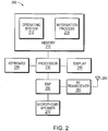
- FIG. 2 is a high-level block diagram of an exemplary communication unit 200 that may be used with the present invention.
- Communication unit 200 comprises a memory 210, a keyboard 220, a CPU 230, a display unit 240, a digital signal processor (DSP) 250, an RF transceiver 260, a microphone/speaker 270 and an antenna 280.
- the keyboard 220 is a conventional keyboard device that enables information to be input into the communication unit by, e.g., a user.
- the processor 230 is a conventional central processing unit (CPU) configured to execute computer-executable instructions contained in memory 210 including instructions that implement aspects of the present invention.
- the display unit 240 is a conventional display unit that enables images (e.g, text, icons, pictures) to be displayed on the communication unit 200.
- the DSP 250 is a conventional digital signal processor that is capable of processing various analog and/or digital signals generated by e.g., the RF transceiver 260 and microphone/speaker 270 as well as providing various digital and/or analog signals to the microphone/speaker 270 and the RF transceiver 260.
- the RF transceiver 260 is a conventional RF transceiver that enables signals to be transferred between the network 100 and the communication unit 200 via antenna 280.
- the microphone/speaker 270 comprises circuitry that enables audio to be input into the communication unit 200 as well as output from the communication unit 200.
- the memory 210 is a computer-readable medium implemented as a random access memory (RAM) comprising RAM devices, such as dynamic RAM (DRAM) devices and/or flash memory devices.
- RAM random access memory
- Memory 210 contains various software and data structures used by processor 230 including software and data structures that implement aspects of the present invention.
- memory 210 includes an operating system 212 and an information process 214.
- the operating system 212 functionally organizes the communication unit 200 by invoking operations in support of software processes and services executing on the communication unit, such as information process 214.
- Information process 214 comprises computer-executable instructions to (a) generate requests for information relative to the communication unit's location, (b) forward the requests to the information server 300, (c) process responses (notifications) to the requests received from the information server 300 and (d) display information (e.g., text, icons, pictures) on the display 240 relative to information contained in the responses.
- Information server 300 is a conventional server that (a) processes requests for information received from nodes in the network (e.g., communication units 200), (b) generates notifications containing the requested information and (c) forwards the notifications to the appropriate nodes.
- information server 300 is a "trusted source” meaning that nodes in the network consider the server 300 as a reliable (trustworthy) source of information.
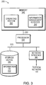
- FIG. 3 is a high-level block diagram of an exemplary information server 300 that may be used with the present invention.
- Server 300 comprises a memory 340 coupled to a processor 330 via a memory bus 350 and, a storage device 360 and a network interface 380 coupled to the processor 330 via an input/output (I/O) bus 370.
- I/O input/output
- server 300 may include other devices, such as keyboards, display units and the like.
- the network interface 380 interfaces the server 300 with the network 100 and enables data (e.g., packets) to be transferred between the server 300 and other nodes in the network 100.
- network interface 380 comprises conventional interface circuitry that incorporates signal, electrical and mechanical characteristics, and interchange circuits, needed to interface with the physical media of the network 100 and protocols running over that media.
- Storage device 360 is a conventional storage device (e.g., a disk) capable of storing information requested by the communication units 200. This information may include, for example, URI information associated with PSAPs.
- the memory 340 is a computer-readable medium implemented as a RAM comprising RAM devices, such as DRAM devices and/or flash memory devices.
- Memory 340 contains various software and data structures used by the processor 330 including software and data structures that implement aspects of the present invention.
- memory 340 includes an operating system 343 and information management services 344.
- the operating system 343 functionally organizes the translation server 300 by invoking operations in support of software processes and services executing on the server 300, such as information management services 344.
- Information management services 344 comprises computer-executable instructions to process requests for information ancillary to the location of an entity in accordance with an aspect of the present invention.
- Storage device 360 comprises information database (DB) 400 which is configured to hold various information requested, e.g., by the communication units 200.
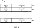
- FIG. 4 illustrates an information DB 400 that may be used with the present invention.
- Information DB 400 is illustratively a table comprising one or more entries 410 wherein each entry contains a location field 420 and an information field 440.
- the location field 420 holds information that represents a location that may be, e.g., associated with a communication unit 200 and the information field 440 holds information that is associated with the location 420.
- This information illustratively includes a URI associated with a PSAP that services the location represented in the location field 420 as well as and text describing a metropolitan area serviced by the PSAP.
- the information field 440 may hold other information ancillary to a location specified in the location field 440, such as a list of stores, restaurants, other places of interest and so on.
- communication units 200 and the information server 300 may be implemented in whole or in part using some combination of hardware and/or software.
- computer-executable instructions and/or computer data that implement aspects of the present invention may be stored in various computer-readable mediums, such as volatile memories, non-volatile memories, flash memories, removable disks, non-removable disks and so on.
- various electromagnetic signals such as wireless signals, electrical signals carried over a wire, optical signals carried over optical fiber and the like, may be encoded to carry computer-executable instructions and/or computer data that implement aspects of the present invention on e.g., a communication network.
- DHCP server 160 may be performed at a single node, such as an intermediate node 180, or spread across some combination of nodes.
- the functions may be implemented as software entities (e.g., processes, tasks, threads) that execute on the various nodes.
- DHCP server 160 may be preconfigured with information about the location of entities (nodes) in network 100.
- An entity e.g., a communication unit 200
- the server responds to the request with a DHCP message that contains the location information.
- entities in network 100 may use other means to determine their location, such as via a Global Positioning System (GPS) system accessible to the entities and the like.
- GPS Global Positioning System
- FIG. 5 is a block diagram of a DHCP message 500 that may be used with the present invention.
- Message 500 includes various DHCP information 520 and a DHCP coordinate location configuration information (LCI) option 540.
- the DHCP information 520 contains conventional DHCP message information, such as an operation (OP) code, client address, "your" address and so on.
- the option 540 contains a code field, a length field, a latitude resolution (LARES) field, a latitude field, a longitude resolution (LORES) field, a longitude field, an altitude type (AT) field, an altitude resolution (ATRES) field, an altitude field and a datum field.
- the code field holds a value that identifies the option 540 as a coordinate LCI option.
- the length field holds a value that represents a length of the option 540, illustratively in bytes.
- the LARES field holds a value that represents a number of valid bits in a fixed-point value of the latitude contained in the latitude field.
- the latitude field holds a value that represents a latitude associated with an entity.
- the LORES field holds a value that represents a number of valid bits in a fixed-point value contained in the longitude field.
- the longitude field holds a value that represents a longitude associated with the entity.
- the AT field holds a value that represents an altitude type associated with the entity (e.g., meters, floors) altitude.
- the ATRES field holds a value that represents a precision associated with the value contained in the altitude field.
- the altitude field holds a value that represents an altitude of the entity.
- the datum field holds a value that represents information about the object 540, e.g., map datum was used for the coordinates given by this option 540.
- a version of the DHCP protocol that may be used with the present invention is described in R. Droms, "Dynamic Host Configuration Protocol," RFC 2131, March 1997 , and a DHCP option for coordinate LCI that may be used with the present invention is described in J. Polk et al. "Dynamic Host Configuration Protocol Option for Coordinate Based Location Configuration Information" RFC 3825, July 2004 , both of which are available from the IETF and are hereby incorporated by reference in their entirety as though fully set forth herein.
- a document that describes how an end system may use DHCP to learn, e.g., a street address associated with the end system is described in H.
- information ancillary to the location of a communication unit 200 is acquired using a query/response type protocol.
- An example of a query/response protocol that may be used with the present invention is SIP.
- the present invention utilizes a subscribe/notify technique to enable a communication unit 200 to acquire information ancillary to a communication unit's location from the information server 300.
- a subscribe/notify technique that may be used with the present invention is described in A. B. Roach, "Session Initiation Protocol (SIP)-Specific Event Notification," RFC 3265 , which is available from the IETF and which is hereby incorporated by reference in its entirety as though fully set forth herein.
- SIP techniques may be used with the present invention.
- a technique that uses the SIP "options” and "200 OK" commands may be used with the present invention.
- query/response protocols may be used with the present invention, such as the well-known Hypertext Transfer Protocol (HTTP), Simple Mail Transfer Protocol (SMTP) and the like.
- HTTP Hypertext Transfer Protocol
- SMTP Simple Mail Transfer Protocol
- FIG. 6 illustrates a dialog between a communication unit 200 and the information server 300 using a subscribe/notify technique in accordance with an aspect of the present invention.
- the dialog begins when a communication unit 200 generates and issues a "subscribe" message to the information server 300.
- the subscribe message contains the location of the communication unit 200 and the type of information relative to its location that is being requested (e.g., the URI and text description of the PSAP that services the communication unit's location).
- the information server 300 acknowledges the subscribe message with a "200 OK" message.
- the information server 300 processes the subscribe message including (a) locating the requested information, (b) generating a "notify” message (notification) that contains the information and (c) transferring the notify message to the communication unit.
- the notify message is a response from the information server 300 to the communication unit 200 that contains the information that was requested by the subscribe message.
- the communication unit 200 receives the notify message and acknowledges it by responding to the information server with a "200 OK" message.
- FIG. 7 is a flow chart of a sequence of steps that may be used to process a request from an entity (e.g., communication unit 200) for information ancillary to a location of the entity at a server (e.g., information server 300) in accordance with an aspect of the present invention.
- the sequence begins at step 705 and proceeds to step 725 where the server receives the request (e.g., a SIP "subscribe" message) containing the location of the entity and identifying the information sought.
- the server acknowledges the request by sending an acknowledgement (e.g., a "200 OK" message) to the entity.
- the server locates the requested information using the location of the entity specified in the request.
- the server determines if the information was found (step 740). If not, the server generates a response indicating an error condition (step 745) and proceeds to step 755. Otherwise, the server generates a response containing the requested information (step 750). At step 755, the response is forwarded to the entity.
- FIG. 8 is a flow chart of a sequence of steps that may be used by an entity (e.g., communication unit 200) to acquire and display information ancillary to its location in accordance with an aspect of the present invention.
- the sequence begins at step 805 and proceeds to step 810 wherein the entity acquires its location.
- the location may be acquired, e.g., using a DHCP server as well as other means, such as via a GPS accessible to the entity.
- a request (e.g., a SIP subscribe message) is generated wherein the request contains the acquired location of the entity as well as identify the information sought.
- the request is then forwarded to the server (step 820).
- a check is performed to determine if a response (e.g., a SIP notify message) containing the requested information was received by the server. If not, an indication that the requested information is not available is made (step 835) and the sequence proceeds to step 895. Otherwise, if a response was received from the server, the response is checked to determine if it indicates an error condition. If so, the sequence proceeds to step 835; otherwise, the sequence proceeds to step 840 where the information contained in the response is used to display the requested information. The sequence ends at step 895.
- a response e.g., a SIP notify message
- communication unit 200a wishes to provide an indication as to whether a URI associated with a PSAP that services the location of the communication unit 200a is known to the communication unit 200a.
- Communication unit 200a determines its location (step 810) by querying the DHCP server 160 for its location information. Specifically, communication unit 200 issues a DHCP message 500 to DHCP server 160 which responds with a DHCP message 500 having a coordinate LCI option 540 that contains the location information (e.g., latitude, longitude and altitude) of communication unit 200a. The communication unit 200a extracts its location information from the coordinate LCI option 540 contained in the DHCP message 500. Note that, as described above, communication unit 200a may determine its location using other means, such as using a GPS system and so on.
- communication unit 200a After it has determined its location, communication unit 200a generates a SIP subscribe message (request) that (a) contains its location and (b) specifies that the URI and metropolitan description of the PSAP associated with its location (step 815) is being requested. Communication unit 200a then forwards the request to the information server 300 (step 820). Specifically, the request is generated by the communication unit's processor 230 ( FIG. 2 ) and forwarded via the RF transceiver 260 to the access point 110a via wireless link 150a. Access point 110a receives the request and forwards it to intermediate node 180a. The intermediate node 180a forwards the request onto network 190 to the information server 300.
- SIP subscribe message that (a) contains its location and (b) specifies that the URI and metropolitan description of the PSAP associated with its location (step 815) is being requested.
- Communication unit 200a then forwards the request to the information server 300 (step 820). Specifically, the request is generated by the communication unit's processor 230 ( FIG. 2
- the request is received by the information server 300 ( FIG. 7 step 725) and is acknowledged (step 730), illustratively using a "200 OK" message.
- the subscribe message is received by the information server's network interface 380 ( FIG. 3 ) and forwarded to the information server's processor 330.
- the processor 330 generates the "200 OK” message and forwards it to the communication unit 200a via network interface 380.
- the "200 OK" message travels on network 190, is eventually received by intermediate node 180a and forwarded to access point 110a which transmits the "200 OK" message to the communication unit 150a.
- Communication unit 200a receives the "200 OK" message and processes it accordingly.
- the processor 330 queries database 400 using the location of communication unit 200a specified in the subscribe message to locate an entry 410 whose location value 420 matches the location specified in the subscribe message. Assume that a matching entry 410 is found (step 740) and that the information field 440 of the matching entry contains a value that represents a URI of the PSAP associated with the location represented in the matching location value 420 as well as information (e.g., text) indicating a metropolitan location (e.g., "Dallas, TX") associated with the PSAP.
- the processor 330 generates a notify message (response) and places the information 440 associated with the matching entry 410 in the generated notify message (step 750). The notify message is then forwarded to communication unit 200a (step 755).
- communication unit 200a determines if the notify message from the server has been received (step 825). Illustratively, the communication unit 200a repeatedly checks for some period of time to determine if the notify message has been received. If the notify message has not been received after some period of time has elapsed, the communication unit 200a concludes that the notify message has not been received from the server and indicates the requested information is not available (step 835). This indication may be in the form of a disabled icon (i.e., an icon that does nothing when selected) displayed on the display 240 that indicates the PSAP is not available. Alternatively, the communication unit 200a may display text or use a coloring scheme to indicate the PSAP URI is unknown on the display 240.
- the communication unit 200a responds to the notify message by generating and forwarding a "200 OK" message (acknowledgement) to the server 300.
- the notify message is received by the communication unit's RF transceiver 260 and transferred to the DSP 250.
- the DSP 250 forwards the notify message to the processor 230 which processes it.
- This processing includes generating a "200 OK" message in a conventional manner and forwarding it to the transceiver 260 which transmits the message onto the network 100 via the wireless link 150a.
- Access point 110a receives the message and forwards it onto the VoIP network 190 where it is eventually received by the server 300.
- the communication unit 200a determines if the notify message indicates an error (step 830). If so, the communication unit 200a indicates that the PSAP information is unavailable as described above. Assuming the notify message does not indicate an error condition, the communication unit 200a indicates that the PSAP URI is available and uses the metropolitan information contained in the notify message to display a metropolitan area associated with the PSAP URI. Illustratively, the PSAP is indicated as being available by displaying an icon representing a PSAP (e.g., an icon with the text "E911") that is enabled on the display unit. The metropolitan information is illustratively displayed as a name of the city associated with the PSAP. Alternatively, the communication unit 200a may display text or use a coloring scheme to indicate the PSAP URI is known.
- the PSAP is indicated as being available by displaying an icon representing a PSAP (e.g., an icon with the text "E911") that is enabled on the display unit.
- the metropolitan information is illustratively displayed as a name of the city associated with the
- the above-described techniques may be adapted to provide information other than PSAP information at a communication unit.
- the above-described technique may be adapted to acquire URIs and display an appropriate indication of businesses (e.g., restaurants, stores, etc.) within a certain locale of the entity. This may include displaying an icon or the like which indicates that the URIs for certain businesses are known to the communication unit.
- the above-described techniques may be adapted to work in networks other than VoIP networks.
- the above-described techniques may be adapted to work in cellular telephone networks.
- a display may be used to indicate, e.g., whether a particular mobile telephone in the cellular network can or cannot reach a PSAP within a particular area (e.g., metro area).
Description
- This invention relates to communication networks and in particular to displaying information ancillary to a location of an entity in a communication network.
- A communication network is a geographically distributed collection of nodes interconnected by communication links and segments for transporting communications (e.g., data) between communication units (end nodes), such as personal computers, certain telephones, personal digital assistants (PDAs), video units and the like. Many types of communication networks are available, with the types ranging from local area networks (LANs) to wide area networks (WANs). LANs typically connect nodes over dedicated private communications links located in the same general physical location, such as a building or campus. WANs, on the other hand, typically connect large numbers of geographically dispersed nodes over long-distance communications links, such as common carrier telephone lines. The Internet is an example of a WAN that connects networks throughout the world, providing global communication between nodes on various networks. The nodes typically communicate over the network by exchanging discrete frames or packets of data according to predefined protocols, such as the Transmission Control Protocol/Internet Protocol (TCP/IP). In this context, a protocol consists of a set of rules defining how the nodes interact with each other.
-
US 6,496,776 discloses a method for retrieving location-centric information. The method includes providing geographic position information of a wireless device to an information system or database and receiving location identifiers based on the geographic position. Each location identifier has related location-centric information that can be viewed by the user of the wireless device.US 2005/111630 discloses an emergency voice/data telecommunication network that includes: a caller device originating an emergency call having a voice portion, and a data portion, a local service interface, a public voice network, a public data network, and an ESN, wherein the ESN determines the appropriate emergency service organization to receive the emergency call and dispatches the voice portion and data portion thereto.US 2003/140056 discloses a method for providing information related to geographical sites based on position coordinates of a user information retrieval device. - A communication network may comprise a series of intermediate nodes (e.g., routers) that are configured to carry communications through the network to the end nodes. Routers are often configured to "route" data, such as packets, between various nodes in the network. Routing is typically performed at layer-3 (L3), which is the network layer of the Open Systems Interconnection Reference Model (OSI-RM). Routers often maintain forwarding databases (FDBs), which are typically configured to hold routing information including L3 addresses and interface information that the router uses to determine where data (e.g., data packets) are to be forwarded in order to reach their destination. For example, a router may have a routing database containing one or more entries wherein each entry contains a L3 destination address of a destination node and interface information about an interface on the router through which the destination node may be reached. A data packet containing a destination address that matches a destination address of an entry in the routing table is forwarded by the router to the interface specified by the matching entry for transfer to the destination node.
- A router may execute one or more routing protocols that enable the router to route packets and exchange routing information with other routers in the network. The routers often use this information to configure (e.g., compute) their FDBs. The routing protocols may include distance-vector protocols, such as the Routing Information Protocol (RIP), or link-state protocols, such as the Intermediate-System-to-Intermediate-System (IS-IS) protocol and the Open Shortest Path First (OSPF) protocol.
- Routing information is typically exchanged between the routers in the form of advertisement messages. For example, nodes executing the IS-IS protocol exchange routing information using an advertisement message called a Link State Packet (LSP). Likewise, nodes executing the OSPF protocol exchange routing information using an advertisement message called a Link State Advertisement (LSA). An intermediate node that acquires an advertisement message may use information contained therein to update its FDB.
- Communication networks are increasingly being used to transport many forms of information including, e.g., voice and video information. Information may be carried on a communication network using various technologies, such as Voice over IP (VoIP). VoIP refers to a group of technologies that may be used to transmit e.g., voice information over communication networks from a source (calling party) to a destination (called party). Such networks may include a plurality of agents that convert e.g., voice and/or video information from its traditional form to a form that is suitable for packet transmission. In other words, the agent encodes, compresses and encapsulates the information into a plurality of data packets that are suitable for being carried by the communication network. Examples of agents include IP telephones, VoIP network interfaces, certain private branch exchanges (PBXs), personal computers (PCs) running communication applications, certain personal digital assistants (PDAs), network devices providing voice gateway services and so on.
- In certain communication networks, such as VoIP networks and IP networks, a session protocol may be employed to establish a VoIP session (connection) that supports a call between a calling party and a called party. An example of a session protocol that is commonly used is the well-known Session Initiation Protocol (SIP) which is described in J. Rosenberg et al., "SIP: Session Initiation Protocol," Internet Engineering Task Force (IETF) Request For Comments (RFC) 3261. SIP operates at the application layer of the OSI-RM and is defined to establish and maintain sessions between endpoints (e.g., SIP-based telephones) in a communication network.
- In accordance with SIP, endpoints are referred to as User Agents (UAs). When a UA comes on-line, it typically registers with a registration service, called a policy data point (PDP), using a SIP register command. The PDP maintains information about the UA which may include its location, how to reach it and authentication information associated with the UA that may be used to authenticate the UA. Typically, after a UA is registered, the UA is available to receive as well as initiate calls.
- When a call is initiated by a calling party to a called party, a session is typically established between the calling and called parties' UAs to support the call. Establishing a session between the parties often involves (a) authenticating both parties and (b) successfully exchanging a sequence of messages between the parties in a predetermined manner. Authentication usually involves ensuring the parties have permission to establish a call in the network. The sequence of messages typically include an invite message issued by the calling party, an OK message issued by the called party followed by an acknowledgement (ACK) issued by the calling party. After the session is established, a channel may then be established, e.g., in accordance with the Real-time Transport Protocol (RTP) described in H. Schulzrinne et al., "RTP: A Transport Protocol for Real-Time Applications," IETF RFC 3550, to carry traffic (e.g., voice information) between the parties.
- Some communication networks, such as IP based communication networks, enable a location associated with a communication unit to be determined. Here, triangulation or other methods may be used e.g., by a server to determine the communication unit's location. The communication unit may then learn its location from the server using a version of the Dynamic Host Configuration Protocol (DHCP) that is extended to provide the location information. An example of an extension to the DHCP protocol that may be used to provide location information is described in J. Polk et al., "Dynamic Host Configuration Protocol Option for Coordinate-based Location Configuration Information," IETF RFC 3825. In a typical arrangement, the communication unit requests its location information from the server using a DHCP request message and the server responds to the communication unit with a DHCP response message that contains the communication unit's location.
- The foregoing and other objects, features and advantages of the invention will be apparent from the following more particular description of preferred embodiments of the invention, as illustrated in the accompanying drawings in which like reference characters refer to the same parts throughout the different views. The drawings are not necessarily to scale, emphasis instead being placed upon illustrating the principles of the invention.
-
FIG. 1 is a block diagram of an exemplary communications network that may implement the present invention. -
FIG. 2 is a block diagram of a communication unit that may be used with the present invention. -
FIG. 3 is a block diagram of a server that may be used with the present invention. -
FIG. 4 illustrates an information database that may be used with the present invention. -
FIG. 5 illustrates a Dynamic Host Configuration Protocol (DHCP) message containing a DHCP option for coordinate location configuration information (LCI) that may be used with the present invention. -
FIG. 6 illustrates an exchange of messages between a communication unit and an information server in accordance with an aspect of the present invention. -
FIG. 7 is a flow chart of a sequence of steps that may be used to process a request for information ancillary to a location of an entity at a server in accordance with an aspect of the present invention. -
FIG. 8 is a flow chart of a sequence of steps that may be used to display information ancillary to a location of an entity in accordance with an aspect of the present invention. - A description of preferred embodiments of the invention follows.
- It should be noted, illustrated embodiments of the present invention, described herein, are described as using the Session Initiation Protocol (SIP) to establish and maintain sessions in a communication network as well as exchange information in the network. A version of the SIP protocol that may be used with the present invention is described in J. Rosenberg et al., "SIP: Session Initiation Protocol," RFC 3261, June 2002, available from the Internet Engineering Task Force (IETF) and is incorporated by reference in its entirely as though fully set forth herein. It should be noted that other protocols, such as the Simple Object Access Protocol (SOAP), Hypertext Transfer Protocol (HTTP), File Transfer Protocol (FTP) and Simple Mail Transfer Protocol (SMTP), may take advantage of aspects of the present invention.
- One problem with some communication networks, especially IP-based communication networks, is that although an entity (e.g., a communication unit) may be able to determine its location using the network, it may not be able to determine certain information ancillary (relative) to its location. For example, Public Safety Access Points (PSAPs) are public agencies that are responsible for answering calls for emergency assistance from other public agencies, such as police, fire and ambulance services. In some IP networks, each PSAP is typically associated with a unique universal resource identifier (URI) which is used to establish communications with the PSAP via the IP networks. Current day IP networks do not provide URI information of PSAPs to a requesting entity relative to the requesting entity's location. Thus, it is possible for the entity to not have a URI for a PSAP that services the entity's current location. Further, since the entity does not have the PSAP URI information, the entity may not be able to provide an indication, e.g., to a user, as to whether the correct URI for a PSAP relative to the entity's location is "known" (available) to the entity.
- The present invention overcomes shortcomings associated with the prior art by providing an indication at an entity (e.g., a communication unit) in a communication network whether information ancillary to an entity's location is known to the entity. Information that is ancillary to a location refers to information related to products and services associated with a location. For example, this information may include information related to a PSAP, police department, fire department or hospital that services the entity's location. Likewise, this information may include restaurants, stores and the like that are in the vicinity of the entity's location.
- According to an aspect of the technique, a request for information is generated by a first entity (e.g., a communication unit) in a communication network wherein the request contains a location of the first entity. The request is forwarded to a second entity (e.g., an information server) in the communication network which is, illustratively, a "trusted source" meaning that the first entity considers the second entity a reliable (trustworthy) source of information. The second entity receives the request and identifies the requested information using the location information contained in the request. A response (notification) containing the identified information is then generated by the second entity and forwarded to the first entity. The first entity receives the notification and processes it accordingly, including displaying the identified information in a manner that indicates the requested information is known. If the requested information is not available, the first entity provides a display indicating the information is not known.
- Advantageously, by providing an indication as to whether information ancillary to the location of the first entity is available or not available at the first entity, the present invention enables a user to readily discern that certain services, such as a PSAP, is accessible by the first entity. Further, advantageously, by ensuring the second entity is a trusted source, this information may be provided with a high degree of assurance that the information is correct.
-
FIG. 1 is a high-level block diagram of anexemplary communication network 100 that may implement the present invention.Communication network 100 comprises a collection ofcommunication links 150, 170 interconnecting a plurality of nodes, such ascommunication units 200, access points 110, Dynamic Host Configuration Protocol (DHCP)server 160, intermediate nodes 180 andinformation server 300, to form an internetwork of nodes. These internetworked nodes communicate by exchanging data packets according to a pre-defined set of network protocols, such as the Transmission Control Protocol/Internet Protocol (TCP/IP) and the Voice over IP (VoIP) protocol. A network protocol as used herein is a formal set of rules that define how data is exchanged between nodes in a communication network. - The intermediate nodes 180 are conventional intermediate nodes, such as routers, that are configured to implement a
VoIP network 190. The access points 110 contain logic that enable thecommunication units 200 to transfer information (e.g., data) between theVoIP network 100 andcommunication units 200. To that end, the access points 110 comprise circuitry which is configured to transmit and receive signals (e.g., radio frequency (RF) signals) that carry the information between the access points 110 and thecommunication units 200 via wireless links 150. Examples of access points that may be used with the present invention include certain Institute of Electrical and Electronic Engineers (IEEE) 802.11 compliant access points as well as certain cellular telephone wireless systems that support the transfer of e.g., data traffic. - The access points 110 interface the
communication units 200 with thenetwork 100 and enable signals be transferred between the communication units 110 and thenetwork 100. Specifically, the access points 110 convert signals received from thecommunication units 200 via wireless links 150 into data packets that are transferred onto thenetwork 100 as well as convert packets received from the network into signals that are transferred to thecommunication units 200. Information (e.g., voice, video) is typically conveyed between thecommunication units 200 using calls which are established innetwork 100 between thecommunication units 200. It should be noted that the present invention may be adapted to work with fixed as well as mobile devices that are able to communicate via a communication network. -
Communication units 200 are conventional communication units, such as wireless telephones, personal digital assistants (PDAs), IP telephones and the like, that enable, e.g., audible and/or visual communications to be converted into signals that are transferred to the access points 110 via wireless links 150.FIG. 2 is a high-level block diagram of anexemplary communication unit 200 that may be used with the present invention.Communication unit 200 comprises amemory 210, akeyboard 220, aCPU 230, adisplay unit 240, a digital signal processor (DSP) 250, anRF transceiver 260, a microphone/speaker 270 and an antenna 280. Thekeyboard 220 is a conventional keyboard device that enables information to be input into the communication unit by, e.g., a user. Theprocessor 230 is a conventional central processing unit (CPU) configured to execute computer-executable instructions contained inmemory 210 including instructions that implement aspects of the present invention. Thedisplay unit 240 is a conventional display unit that enables images (e.g, text, icons, pictures) to be displayed on thecommunication unit 200. TheDSP 250 is a conventional digital signal processor that is capable of processing various analog and/or digital signals generated by e.g., theRF transceiver 260 and microphone/speaker 270 as well as providing various digital and/or analog signals to the microphone/speaker 270 and theRF transceiver 260. TheRF transceiver 260 is a conventional RF transceiver that enables signals to be transferred between thenetwork 100 and thecommunication unit 200 via antenna 280. The microphone/speaker 270 comprises circuitry that enables audio to be input into thecommunication unit 200 as well as output from thecommunication unit 200. - The
memory 210 is a computer-readable medium implemented as a random access memory (RAM) comprising RAM devices, such as dynamic RAM (DRAM) devices and/or flash memory devices.Memory 210 contains various software and data structures used byprocessor 230 including software and data structures that implement aspects of the present invention. Specifically,memory 210 includes anoperating system 212 and aninformation process 214. Theoperating system 212 functionally organizes thecommunication unit 200 by invoking operations in support of software processes and services executing on the communication unit, such asinformation process 214.Information process 214, as will be described further below, comprises computer-executable instructions to (a) generate requests for information relative to the communication unit's location, (b) forward the requests to theinformation server 300, (c) process responses (notifications) to the requests received from theinformation server 300 and (d) display information (e.g., text, icons, pictures) on thedisplay 240 relative to information contained in the responses. -
Information server 300 is a conventional server that (a) processes requests for information received from nodes in the network (e.g., communication units 200), (b) generates notifications containing the requested information and (c) forwards the notifications to the appropriate nodes. Illustratively,information server 300 is a "trusted source" meaning that nodes in the network consider theserver 300 as a reliable (trustworthy) source of information. -
FIG. 3 is a high-level block diagram of anexemplary information server 300 that may be used with the present invention.Server 300 comprises amemory 340 coupled to aprocessor 330 via a memory bus 350 and, astorage device 360 and anetwork interface 380 coupled to theprocessor 330 via an input/output (I/O)bus 370. It should be noted thatserver 300 may include other devices, such as keyboards, display units and the like. Thenetwork interface 380 interfaces theserver 300 with thenetwork 100 and enables data (e.g., packets) to be transferred between theserver 300 and other nodes in thenetwork 100. To that end,network interface 380 comprises conventional interface circuitry that incorporates signal, electrical and mechanical characteristics, and interchange circuits, needed to interface with the physical media of thenetwork 100 and protocols running over that media.Storage device 360 is a conventional storage device (e.g., a disk) capable of storing information requested by thecommunication units 200. This information may include, for example, URI information associated with PSAPs. - The
memory 340 is a computer-readable medium implemented as a RAM comprising RAM devices, such as DRAM devices and/or flash memory devices.Memory 340 contains various software and data structures used by theprocessor 330 including software and data structures that implement aspects of the present invention. Specifically,memory 340 includes anoperating system 343 and information management services 344. Theoperating system 343 functionally organizes thetranslation server 300 by invoking operations in support of software processes and services executing on theserver 300, such as information management services 344.Information management services 344, as will be described further below, comprises computer-executable instructions to process requests for information ancillary to the location of an entity in accordance with an aspect of the present invention. -
Storage device 360 comprises information database (DB) 400 which is configured to hold various information requested, e.g., by thecommunication units 200.FIG. 4 illustrates aninformation DB 400 that may be used with the present invention.Information DB 400 is illustratively a table comprising one ormore entries 410 wherein each entry contains alocation field 420 and aninformation field 440. Thelocation field 420 holds information that represents a location that may be, e.g., associated with acommunication unit 200 and theinformation field 440 holds information that is associated with thelocation 420. This information illustratively includes a URI associated with a PSAP that services the location represented in thelocation field 420 as well as and text describing a metropolitan area serviced by the PSAP. It should be noted that theinformation field 440 may hold other information ancillary to a location specified in thelocation field 440, such as a list of stores, restaurants, other places of interest and so on. - It should be noted that functions performed by
communication units 200 and theinformation server 300, including functions that implement aspects of the present invention, may be implemented in whole or in part using some combination of hardware and/or software. It should be further noted that computer-executable instructions and/or computer data that implement aspects of the present invention may be stored in various computer-readable mediums, such as volatile memories, non-volatile memories, flash memories, removable disks, non-removable disks and so on. In addition, it should be noted that various electromagnetic signals, such as wireless signals, electrical signals carried over a wire, optical signals carried over optical fiber and the like, may be encoded to carry computer-executable instructions and/or computer data that implement aspects of the present invention on e.g., a communication network. Moreover, it should be further noted that some or all of the functions performed by, e.g.,information server 300 andDHCP server 160 may be performed at a single node, such as an intermediate node 180, or spread across some combination of nodes. Here, the functions may be implemented as software entities (e.g., processes, tasks, threads) that execute on the various nodes. - In accordance with an aspect of the present invention,
DHCP server 160 may be preconfigured with information about the location of entities (nodes) innetwork 100. An entity (e.g., a communication unit 200) may learn its location from theserver 160 by (a) generating a DHCP message to request the information and (b) forwarding the generated request to theDHCP server 160. The server responds to the request with a DHCP message that contains the location information. It should be noted that entities innetwork 100 may use other means to determine their location, such as via a Global Positioning System (GPS) system accessible to the entities and the like. -
FIG. 5 is a block diagram of aDHCP message 500 that may be used with the present invention.Message 500 includesvarious DHCP information 520 and a DHCP coordinate location configuration information (LCI)option 540. TheDHCP information 520 contains conventional DHCP message information, such as an operation (OP) code, client address, "your" address and so on. - The
option 540 contains a code field, a length field, a latitude resolution (LARES) field, a latitude field, a longitude resolution (LORES) field, a longitude field, an altitude type (AT) field, an altitude resolution (ATRES) field, an altitude field and a datum field. The code field holds a value that identifies theoption 540 as a coordinate LCI option. The length field holds a value that represents a length of theoption 540, illustratively in bytes. The LARES field holds a value that represents a number of valid bits in a fixed-point value of the latitude contained in the latitude field. The latitude field holds a value that represents a latitude associated with an entity. The LORES field holds a value that represents a number of valid bits in a fixed-point value contained in the longitude field. The longitude field holds a value that represents a longitude associated with the entity. The AT field holds a value that represents an altitude type associated with the entity (e.g., meters, floors) altitude. The ATRES field holds a value that represents a precision associated with the value contained in the altitude field. The altitude field holds a value that represents an altitude of the entity. The datum field holds a value that represents information about theobject 540, e.g., map datum was used for the coordinates given by thisoption 540. - A version of the DHCP protocol that may be used with the present invention is described in R. Droms, "Dynamic Host Configuration Protocol," RFC 2131, March 1997, and a DHCP option for coordinate LCI that may be used with the present invention is described in J. Polk et al. "Dynamic Host Configuration Protocol Option for Coordinate Based Location Configuration Information" RFC 3825, July 2004, both of which are available from the IETF and are hereby incorporated by reference in their entirety as though fully set forth herein. A document that describes how an end system may use DHCP to learn, e.g., a street address associated with the end system is described in H. Schulzrinne, "Dynamic Host Configuration Protocol (DHCPv4 and DHCPv6) Option for Civic Addresses Configuration Information", draft-ietf-geopriv-dhcp-civil-09.txt, which is available from the IETF and is hereby incorporated by reference as though fully set forth herein.
- In accordance with an aspect of the present invention, information ancillary to the location of a
communication unit 200 is acquired using a query/response type protocol. An example of a query/response protocol that may be used with the present invention is SIP. Specifically, the present invention utilizes a subscribe/notify technique to enable acommunication unit 200 to acquire information ancillary to a communication unit's location from theinformation server 300. A subscribe/notify technique that may be used with the present invention is described in A. B. Roach, "Session Initiation Protocol (SIP)-Specific Event Notification," RFC 3265, which is available from the IETF and which is hereby incorporated by reference in its entirety as though fully set forth herein. It should be noted that other SIP techniques may be used with the present invention. For example, a technique that uses the SIP "options" and "200 OK" commands may be used with the present invention. It should be further noted that other query/response protocols may be used with the present invention, such as the well-known Hypertext Transfer Protocol (HTTP), Simple Mail Transfer Protocol (SMTP) and the like. A version of HTTP that may be used with the present invention is described in R. Fielding, "Hypertext Transfer Protocol - HTTP/ 1.1", RFC 2616 and a version of SMTP that may be used with the present invention is described in J. Klensin, "Simple Mail Transfer Protocol", RFC 2821, both of which are available from the IETF and both are hereby incorporated by reference as though fully set forth herein. -
FIG. 6 illustrates a dialog between acommunication unit 200 and theinformation server 300 using a subscribe/notify technique in accordance with an aspect of the present invention. The dialog begins when acommunication unit 200 generates and issues a "subscribe" message to theinformation server 300. The subscribe message contains the location of thecommunication unit 200 and the type of information relative to its location that is being requested (e.g., the URI and text description of the PSAP that services the communication unit's location). Theinformation server 300 acknowledges the subscribe message with a "200 OK" message. Theinformation server 300 processes the subscribe message including (a) locating the requested information, (b) generating a "notify" message (notification) that contains the information and (c) transferring the notify message to the communication unit. The notify message is a response from theinformation server 300 to thecommunication unit 200 that contains the information that was requested by the subscribe message. Thecommunication unit 200 receives the notify message and acknowledges it by responding to the information server with a "200 OK" message. -
FIG. 7 is a flow chart of a sequence of steps that may be used to process a request from an entity (e.g., communication unit 200) for information ancillary to a location of the entity at a server (e.g., information server 300) in accordance with an aspect of the present invention. The sequence begins atstep 705 and proceeds to step 725 where the server receives the request (e.g., a SIP "subscribe" message) containing the location of the entity and identifying the information sought. Next, atstep 730, the server acknowledges the request by sending an acknowledgement (e.g., a "200 OK" message) to the entity. Atstep 735, the server locates the requested information using the location of the entity specified in the request. The server then determines if the information was found (step 740). If not, the server generates a response indicating an error condition (step 745) and proceeds to step 755. Otherwise, the server generates a response containing the requested information (step 750). Atstep 755, the response is forwarded to the entity. -
FIG. 8 is a flow chart of a sequence of steps that may be used by an entity (e.g., communication unit 200) to acquire and display information ancillary to its location in accordance with an aspect of the present invention. The sequence begins atstep 805 and proceeds to step 810 wherein the entity acquires its location. As noted above, the location may be acquired, e.g., using a DHCP server as well as other means, such as via a GPS accessible to the entity. - Next, at
step 815, a request (e.g., a SIP subscribe message) is generated wherein the request contains the acquired location of the entity as well as identify the information sought. The request is then forwarded to the server (step 820). Atstep 825, a check is performed to determine if a response (e.g., a SIP notify message) containing the requested information was received by the server. If not, an indication that the requested information is not available is made (step 835) and the sequence proceeds to step 895. Otherwise, if a response was received from the server, the response is checked to determine if it indicates an error condition. If so, the sequence proceeds to step 835; otherwise, the sequence proceeds to step 840 where the information contained in the response is used to display the requested information. The sequence ends atstep 895. - For example, referring to
FIGs. 1 ,7 and8 , assume thatcommunication unit 200a wishes to provide an indication as to whether a URI associated with a PSAP that services the location of thecommunication unit 200a is known to thecommunication unit 200a.Communication unit 200a determines its location (step 810) by querying theDHCP server 160 for its location information. Specifically,communication unit 200 issues aDHCP message 500 toDHCP server 160 which responds with aDHCP message 500 having a coordinateLCI option 540 that contains the location information (e.g., latitude, longitude and altitude) ofcommunication unit 200a. Thecommunication unit 200a extracts its location information from the coordinateLCI option 540 contained in theDHCP message 500. Note that, as described above,communication unit 200a may determine its location using other means, such as using a GPS system and so on. - After it has determined its location,
communication unit 200a generates a SIP subscribe message (request) that (a) contains its location and (b) specifies that the URI and metropolitan description of the PSAP associated with its location (step 815) is being requested.Communication unit 200a then forwards the request to the information server 300 (step 820). Specifically, the request is generated by the communication unit's processor 230 (FIG. 2 ) and forwarded via theRF transceiver 260 to theaccess point 110a viawireless link 150a.Access point 110a receives the request and forwards it tointermediate node 180a. Theintermediate node 180a forwards the request ontonetwork 190 to theinformation server 300. - Eventually the request is received by the information server 300 (
FIG. 7 step 725) and is acknowledged (step 730), illustratively using a "200 OK" message. Specifically, the subscribe message is received by the information server's network interface 380 (FIG. 3 ) and forwarded to the information server'sprocessor 330. Theprocessor 330 generates the "200 OK" message and forwards it to thecommunication unit 200a vianetwork interface 380. The "200 OK" message travels onnetwork 190, is eventually received byintermediate node 180a and forwarded to accesspoint 110a which transmits the "200 OK" message to thecommunication unit 150a.Communication unit 200a receives the "200 OK" message and processes it accordingly. - At
step 735, theprocessor 330queries database 400 using the location ofcommunication unit 200a specified in the subscribe message to locate anentry 410 whoselocation value 420 matches the location specified in the subscribe message. Assume that amatching entry 410 is found (step 740) and that theinformation field 440 of the matching entry contains a value that represents a URI of the PSAP associated with the location represented in the matchinglocation value 420 as well as information (e.g., text) indicating a metropolitan location (e.g., "Dallas, TX") associated with the PSAP. Theprocessor 330 generates a notify message (response) and places theinformation 440 associated with thematching entry 410 in the generated notify message (step 750). The notify message is then forwarded tocommunication unit 200a (step 755). - Meanwhile,
communication unit 200a determines if the notify message from the server has been received (step 825). Illustratively, thecommunication unit 200a repeatedly checks for some period of time to determine if the notify message has been received. If the notify message has not been received after some period of time has elapsed, thecommunication unit 200a concludes that the notify message has not been received from the server and indicates the requested information is not available (step 835). This indication may be in the form of a disabled icon (i.e., an icon that does nothing when selected) displayed on thedisplay 240 that indicates the PSAP is not available. Alternatively, thecommunication unit 200a may display text or use a coloring scheme to indicate the PSAP URI is unknown on thedisplay 240. - Assuming
communication unit 200a has received the notify message, thecommunication unit 200a responds to the notify message by generating and forwarding a "200 OK" message (acknowledgement) to theserver 300. Specifically, the notify message is received by the communication unit'sRF transceiver 260 and transferred to theDSP 250. TheDSP 250, in turn, forwards the notify message to theprocessor 230 which processes it. This processing includes generating a "200 OK" message in a conventional manner and forwarding it to thetransceiver 260 which transmits the message onto thenetwork 100 via thewireless link 150a.Access point 110a receives the message and forwards it onto theVoIP network 190 where it is eventually received by theserver 300. - In processing the notify message further, the
communication unit 200a determines if the notify message indicates an error (step 830). If so, thecommunication unit 200a indicates that the PSAP information is unavailable as described above. Assuming the notify message does not indicate an error condition, thecommunication unit 200a indicates that the PSAP URI is available and uses the metropolitan information contained in the notify message to display a metropolitan area associated with the PSAP URI. Illustratively, the PSAP is indicated as being available by displaying an icon representing a PSAP (e.g., an icon with the text "E911") that is enabled on the display unit. The metropolitan information is illustratively displayed as a name of the city associated with the PSAP. Alternatively, thecommunication unit 200a may display text or use a coloring scheme to indicate the PSAP URI is known. - It should be noted that the above-described techniques may be adapted to provide information other than PSAP information at a communication unit. For example, the above-described technique may be adapted to acquire URIs and display an appropriate indication of businesses (e.g., restaurants, stores, etc.) within a certain locale of the entity. This may include displaying an icon or the like which indicates that the URIs for certain businesses are known to the communication unit.
- It should be noted that the above-described techniques may be adapted to work in networks other than VoIP networks. For example, the above-described techniques may be adapted to work in cellular telephone networks. Here, a display may be used to indicate, e.g., whether a particular mobile telephone in the cellular network can or cannot reach a PSAP within a particular area (e.g., metro area).
- While this invention has been particularly shown and described with references to preferred embodiments thereof, it will be understood by those skilled in the art that various changes in form and details may be made therein without departing from the scope of the invention encompassed by the appended claims.
Claims (7)
- A method of displaying information ancillary to a location of a first entity in a communication network, the method comprising:generating (810), by the first entity, a first Dynamic Host Configuration Protocol, DHCP, request for a location of the first entity;forwarding (810) the first request to a DHCP external server; andreceiving (810), from the DHCP external server, a response containing the first entity's location;generating (815) a second request for a Uniform Resource Identifier, URI, and description associated with a public safety access point, PSAP, that services the location of the first entity, wherein the second request includes the location of the first entity;forwarding (820) the second request to a second entity;waiting for a notification from the second entity for up to a period of time;if the notification from the second entity is received within the period of time (825) and contains the requested URI and description associated with the PSAP that services the location of the first entity, generating (840) a display based on the received URI and description associated with the PSAP that services the location of the first entity, and displaying (840) the generated display at the first entity;if the notification from the second entity is received (825) but indicates the information is not available (830), displaying (835) an indication that the requested information is not available; andif the notification is not received within the period of time (825), displaying (835) an indication that the requested information is not available.
- A method as defined in claim 1, wherein the second entity is a trusted source.
- A method as defined in claim 1, wherein the second request contains a coordinate location configuration information, LCI, option for holding information associated with the first entity.
- A method as defined in claim 1, wherein the second request is a Session Initiation Protocol subscribe message.
- A method as defined in claim 1, wherein the indication that the requested information is not available is displayed as a disabled icon.
- A method as defined in claim 1, wherein the indication that the requested information is not available is displayed using a coloring scheme that indicates the information is not available.
- A communication unit (200) comprising:
a processor (230) configured to perform all steps of a method according to any one of the preceding claims.
Applications Claiming Priority (2)
| Application Number | Priority Date | Filing Date | Title |
|---|---|---|---|
| US70459005P | 2005-08-01 | 2005-08-01 | |
| PCT/US2006/029669 WO2007016452A2 (en) | 2005-08-01 | 2006-07-31 | Technique for displaying information ancillary to a location of an entity in a communication network |
Publications (3)
| Publication Number | Publication Date |
|---|---|
| EP1911302A2 EP1911302A2 (en) | 2008-04-16 |
| EP1911302A4 EP1911302A4 (en) | 2016-09-07 |
| EP1911302B1 true EP1911302B1 (en) | 2018-12-05 |
Family
ID=37709258
Family Applications (1)
| Application Number | Title | Priority Date | Filing Date |
|---|---|---|---|
| EP06788948.5A Active EP1911302B1 (en) | 2005-08-01 | 2006-07-31 | Technique for displaying information ancillary to a location of an entity in a communication network |
Country Status (3)
| Country | Link |
|---|---|
| US (1) | US8190134B2 (en) |
| EP (1) | EP1911302B1 (en) |
| WO (1) | WO2007016452A2 (en) |
Families Citing this family (9)
| Publication number | Priority date | Publication date | Assignee | Title |
|---|---|---|---|---|
| US20070121798A1 (en) * | 2005-10-20 | 2007-05-31 | Jon Croy | Public service answering point (PSAP) proxy |
| EP2051550B1 (en) * | 2007-10-19 | 2012-07-11 | Nokia Siemens Networks Oy | Acquiring a service number and further information |
| US9246954B2 (en) | 2007-12-13 | 2016-01-26 | Nokia Technologies Oy | Location tagging method for packet based signalling |
| US8938211B2 (en) | 2008-12-22 | 2015-01-20 | Qualcomm Incorporated | Providing and utilizing maps in location determination based on RSSI and RTT data |
| US20100157848A1 (en) * | 2008-12-22 | 2010-06-24 | Qualcomm Incorporated | Method and apparatus for providing and utilizing local maps and annotations in location determination |
| US8938355B2 (en) * | 2009-03-13 | 2015-01-20 | Qualcomm Incorporated | Human assisted techniques for providing local maps and location-specific annotated data |
| US20110093339A1 (en) * | 2009-09-10 | 2011-04-21 | Morton Timothy B | System and method for the service of advertising content to a consumer based on the detection of zone events in a retail environment |
| US20110060652A1 (en) * | 2009-09-10 | 2011-03-10 | Morton Timothy B | System and method for the service of advertising content to a consumer based on the detection of zone events in a retail environment |
| US9080882B2 (en) | 2012-03-02 | 2015-07-14 | Qualcomm Incorporated | Visual OCR for positioning |
Family Cites Families (65)
| Publication number | Priority date | Publication date | Assignee | Title |
|---|---|---|---|---|
| GB2278196A (en) | 1993-05-18 | 1994-11-23 | William Michael Frederi Taylor | Information system using GPS |
| US6321158B1 (en) * | 1994-06-24 | 2001-11-20 | Delorme Publishing Company | Integrated routing/mapping information |
| US6336074B1 (en) * | 1995-05-12 | 2002-01-01 | Trimble Navigation Limited | Satellite navigation receiver with map graphics and hypertext driven by a PDF database |
| US6049711A (en) * | 1995-08-23 | 2000-04-11 | Teletrac, Inc. | Method and apparatus for providing location-based information services |
| US5930699A (en) * | 1996-11-12 | 1999-07-27 | Ericsson Inc. | Address retrieval system |
| US6061560A (en) * | 1997-04-30 | 2000-05-09 | Nortel Networks Corporation | Method and apparatus for delivering and presenting calling name information in a wireless communications system |
| US6088594A (en) * | 1997-11-26 | 2000-07-11 | Ericsson Inc. | System and method for positioning a mobile terminal using a terminal based browser |
| US6285317B1 (en) * | 1998-05-01 | 2001-09-04 | Lucent Technologies Inc. | Navigation system with three-dimensional display |
| FI106823B (en) * | 1998-10-23 | 2001-04-12 | Nokia Mobile Phones Ltd | Information retrieval system |
| US7039688B2 (en) * | 1998-11-12 | 2006-05-02 | Ricoh Co., Ltd. | Method and apparatus for automatic network configuration |
| US6345294B1 (en) * | 1999-04-19 | 2002-02-05 | Cisco Technology, Inc. | Methods and apparatus for remote configuration of an appliance on a network |
| US6385615B1 (en) * | 1999-05-21 | 2002-05-07 | Cisco Technology, Inc. | Communicating network information using universal resource locators |
| US6907243B1 (en) * | 1999-06-09 | 2005-06-14 | Cisco Technology, Inc. | Method and system for dynamic soft handoff resource allocation in a wireless network |
| EP1106965B1 (en) * | 1999-06-22 | 2007-08-22 | Mitsubishi Denki Kabushiki Kaisha | Mobile terminal and server in navigation system |
| US6393126B1 (en) * | 1999-06-23 | 2002-05-21 | Datum, Inc. | System and methods for generating trusted and authenticatable time stamps for electronic documents |
| US6496702B1 (en) * | 1999-08-06 | 2002-12-17 | Genesys Telecommunications Laboratories, Inc. | Method and apparatus for providing enhanced communication capability for mobile devices on a virtual private network (VPN) |
| US6952800B1 (en) * | 1999-09-03 | 2005-10-04 | Cisco Technology, Inc. | Arrangement for controlling and logging voice enabled web applications using extensible markup language documents |
| US6459782B1 (en) * | 1999-11-10 | 2002-10-01 | Goldstar Information Technologies, Llc | System and method of developing mapping and directions from caller ID |
| US6826472B1 (en) * | 1999-12-10 | 2004-11-30 | Tele Atlas North America, Inc. | Method and apparatus to generate driving guides |
| US6806814B1 (en) * | 2000-01-07 | 2004-10-19 | Cisco Technology, Inc. | Real-time positioning internet protocol method and apparatus |
| US6779154B1 (en) * | 2000-02-01 | 2004-08-17 | Cisco Technology, Inc. | Arrangement for reversibly converting extensible markup language documents to hypertext markup language documents |
| US6496776B1 (en) | 2000-02-29 | 2002-12-17 | Brad W. Blumberg | Position-based information access device and method |
| US6609005B1 (en) * | 2000-03-28 | 2003-08-19 | Leap Wireless International, Inc. | System and method for displaying the location of a wireless communications device wiring a universal resource locator |
| AU2001249753A1 (en) * | 2000-03-30 | 2001-10-15 | Sabyasachi Bain | Address presentation system interface |
| US6874084B1 (en) * | 2000-05-02 | 2005-03-29 | International Business Machines Corporation | Method and apparatus for establishing a secure communication connection between a java application and secure server |
| AU2001264899A1 (en) | 2000-05-24 | 2001-12-03 | Switchboard Incorporated | Geographical comparison system and method |
| US6552670B2 (en) * | 2000-05-26 | 2003-04-22 | Switchboard Incorporated | Location encoder |
| US6545596B1 (en) | 2000-06-30 | 2003-04-08 | Cisco Technology, Inc. | Presenting information to mobile targets |
| US6775833B1 (en) * | 2000-08-08 | 2004-08-10 | Cisco Technology, Inc. | Method of managing a scalable interface communication system |
| JP2002116033A (en) | 2000-10-10 | 2002-04-19 | Nippon Signal Co Ltd:The | Device and method for landmark guidance, information storage medium, and device and method for landmark registration |
| US6721580B1 (en) | 2000-10-27 | 2004-04-13 | Cisco Technology, Inc. | Ensuring emergency availability of communications devices |
| US6744858B1 (en) * | 2001-01-26 | 2004-06-01 | Telcontrol, Inc. | System and method for supporting multiple call centers |
| US6907254B1 (en) * | 2001-03-08 | 2005-06-14 | Cisco Technology, Inc. | Method and apparatus for controlling a quiet zone for wireless units |
| FR2822994B1 (en) * | 2001-03-30 | 2004-05-21 | Bouygues Telecom Sa | ASSISTANCE TO THE DRIVER OF A MOTOR VEHICLE |
| US6704406B1 (en) | 2001-05-29 | 2004-03-09 | Cisco Technology, Inc. | Automated route plan generation |
| US6665611B1 (en) | 2001-06-19 | 2003-12-16 | Cisco Technology, Inc. | System for discovering and maintaining geographic location information in a computer network to enable emergency services |
| US7082365B2 (en) * | 2001-08-16 | 2006-07-25 | Networks In Motion, Inc. | Point of interest spatial rating search method and system |
| US7486958B2 (en) * | 2001-09-05 | 2009-02-03 | Networks In Motion, Inc. | System and method for maintaining an online point-of-interest directory |
| US7870025B2 (en) * | 2001-09-20 | 2011-01-11 | Intuit Inc. | Vendor comparison, advertising and switching |
| US6754335B1 (en) | 2001-09-27 | 2004-06-22 | Cisco Technology, Inc. | Call center with location queuing and dispatching |
| US7103040B2 (en) * | 2001-11-19 | 2006-09-05 | Telefonaktieboaget Lm Ericsson (Publ) | Method and apparatus for identifying a node for data communications using its geographical location |
| US6680998B1 (en) | 2001-11-19 | 2004-01-20 | Cisco Technology, Inc. | Providing private network information during emergency calls |
| US6731239B2 (en) * | 2002-01-18 | 2004-05-04 | Ford Motor Company | System and method for retrieving information using position coordinates |
| US6775362B1 (en) | 2002-03-06 | 2004-08-10 | Alcatel | Graphical telephone system |
| US20030218064A1 (en) * | 2002-03-12 | 2003-11-27 | Storcard, Inc. | Multi-purpose personal portable electronic system |
| EP1355505B1 (en) * | 2002-04-11 | 2013-07-24 | Accenture Global Services Limited | Localization of radio-frequency transceivers |
| US7116985B2 (en) * | 2002-06-14 | 2006-10-03 | Cingular Wireless Ii, Llc | Method for providing location-based services in a wireless network, such as varying levels of services |
| US6940954B1 (en) * | 2002-09-06 | 2005-09-06 | Cisco Technology, Inc. | Arrangement for retrieving recorded audio announcements from a messaging system for identification of a calling party |
| US20040088346A1 (en) * | 2002-10-31 | 2004-05-06 | Philipp Hassler | Geo-server interface |
| US8903385B2 (en) * | 2003-05-29 | 2014-12-02 | Kyocera Corporation | Wireless transmission system |
| US7440442B2 (en) * | 2003-10-21 | 2008-10-21 | 3Com Corporation | IP-based enhanced emergency services using intelligent client devices |
| US7016478B2 (en) * | 2003-11-24 | 2006-03-21 | Lucent Technologies Inc. | 911 emergency voice/data telecommunication network |
| US7260186B2 (en) * | 2004-03-23 | 2007-08-21 | Telecommunication Systems, Inc. | Solutions for voice over internet protocol (VoIP) 911 location services |
| US7228141B2 (en) * | 2003-12-23 | 2007-06-05 | Cisco Technology, Inc. | Providing location-specific services to a mobile node |
| US7349535B2 (en) * | 2004-03-03 | 2008-03-25 | Cisco Technology, Inc. | Method and system for automatic call distribution based on location information for call center agents |
| US7123693B2 (en) * | 2004-03-13 | 2006-10-17 | Intrado Inc. | Method and apparatus for increasing the reliability of an emergency call communication network |
| US20050235056A1 (en) * | 2004-04-19 | 2005-10-20 | Ken-Li Chen | Location system |
| US7789308B2 (en) * | 2004-05-13 | 2010-09-07 | Cisco Technology, Inc. | Locating and provisioning devices in a network |
| US7031728B2 (en) * | 2004-09-21 | 2006-04-18 | Beyer Jr Malcolm K | Cellular phone/PDA communication system |
| US7508922B2 (en) * | 2005-02-25 | 2009-03-24 | Verizon Business Global Llc | Systems and methods for providing 9-1-1 services to nomadic internet telephony callers |
| US7602886B1 (en) * | 2005-07-20 | 2009-10-13 | Sprint Spectrum L.P. | Method and system for using a network-provided location for voice-over-packet emergency services calls |
| US20070027997A1 (en) * | 2005-07-29 | 2007-02-01 | Cisco Technology, Inc. | Technique for translating location information |
| US20070025337A1 (en) * | 2005-07-29 | 2007-02-01 | Cisco Technology, Inc. | Technique for providing ancillary information to an entity in a communications network |
| US8412804B2 (en) * | 2005-07-29 | 2013-04-02 | Cisco Technology, Inc. | Acquiring information in a communication network relative to a location |
| US20070050128A1 (en) * | 2005-08-31 | 2007-03-01 | Garmin Ltd., A Cayman Islands Corporation | Method and system for off-board navigation with a portable device |
-
2006
- 2006-07-31 US US11/496,272 patent/US8190134B2/en active Active
- 2006-07-31 WO PCT/US2006/029669 patent/WO2007016452A2/en active Application Filing
- 2006-07-31 EP EP06788948.5A patent/EP1911302B1/en active Active
Non-Patent Citations (1)
| Title |
|---|
| None * |
Also Published As
| Publication number | Publication date |
|---|---|
| US8190134B2 (en) | 2012-05-29 |
| US20070026847A1 (en) | 2007-02-01 |
| EP1911302A4 (en) | 2016-09-07 |
| WO2007016452A2 (en) | 2007-02-08 |
| WO2007016452A3 (en) | 2007-08-02 |
| EP1911302A2 (en) | 2008-04-16 |
Similar Documents
| Publication | Publication Date | Title |
|---|---|---|
| EP1911250B1 (en) | Technique for translating location information | |
| EP1911302B1 (en) | Technique for displaying information ancillary to a location of an entity in a communication network | |
| US7629882B2 (en) | Method and apparatus for determining a physical location of a customer | |
| US9137315B2 (en) | E911 location server | |
| US8265068B2 (en) | Mapping of IP phones for E911 | |
| US8068586B2 (en) | Determining a local emergency dial-string | |
| US7519052B2 (en) | Apparatus and method to provide current location information services in a network | |
| US20080065775A1 (en) | Location data-URL mechanism | |
| US8412804B2 (en) | Acquiring information in a communication network relative to a location | |
| Rosen et al. | Framework for emergency calling using internet multimedia | |
| US20070025337A1 (en) | Technique for providing ancillary information to an entity in a communications network | |
| EP1843524A1 (en) | Locating devices | |
| US8681782B2 (en) | Method and system for routing a voice-over-packet emergency services call to an appropriate public safety answering point (PSAP) | |
| US8787870B2 (en) | Method, apparatus and computer program product for providing emergency service validation | |
| US9215565B2 (en) | Method, system, and computer program product for providing location based services | |
| WO2007061790A2 (en) | Voice over internet protocol (voip) mobility detection | |
| US20090052442A1 (en) | Automatically routing session initiation protocol (sip) communications from a consumer device | |
| US20080153455A1 (en) | System, method and program for managing voip calls such as 911 calls from mobile devices | |
| US11444987B2 (en) | Systems and methods for user capability exchange across networks | |
| US20140364090A1 (en) | Gateway for voice communication | |
| US11558507B1 (en) | Location determination and telephone number distribution for emergency calls | |
| Polk et al. | ecrit B. Rosen Internet-Draft NeuStar Intended status: Standards Track H. Schulzrinne Expires: August 28, 2008 Columbia U. | |
| Rosen et al. | RFC 6443: Framework for Emergency Calling Using Internet Multimedia |
Legal Events
| Date | Code | Title | Description |
|---|---|---|---|
| PUAI | Public reference made under article 153(3) epc to a published international application that has entered the european phase |
Free format text: ORIGINAL CODE: 0009012 |
|
| 17P | Request for examination filed |
Effective date: 20071213 |
|
| AK | Designated contracting states |
Kind code of ref document: A2 Designated state(s): AT BE BG CH CY CZ DE DK EE ES FI FR GB GR HU IE IS IT LI LT LU LV MC NL PL PT RO SE SI SK TR |
|
| RIN1 | Information on inventor provided before grant (corrected) |
Inventor name: POLK, JAMES, M. Inventor name: JENNINGS, CULLEN, F. |
|
| RAP1 | Party data changed (applicant data changed or rights of an application transferred) |
Owner name: CISCO TECHNOLOGY, INC. |
|
| RIN1 | Information on inventor provided before grant (corrected) |
Inventor name: JENNINGS, CULLEN, F. Inventor name: POLK, JAMES, M. |
|
| DAX | Request for extension of the european patent (deleted) | ||
| REG | Reference to a national code |
Ref country code: DE Ref legal event code: R079 Ref document number: 602006057007 Country of ref document: DE Free format text: PREVIOUS MAIN CLASS: H04Q0007220000 Ipc: H04M0003493000 |
|
| A4 | Supplementary search report drawn up and despatched |
Effective date: 20160810 |
|
| RIC1 | Information provided on ipc code assigned before grant |
Ipc: H04M 3/42 20060101ALI20160804BHEP Ipc: H04L 29/08 20060101ALI20160804BHEP Ipc: H04W 4/02 20090101ALI20160804BHEP Ipc: H04M 7/00 20060101ALI20160804BHEP Ipc: H04L 29/06 20060101ALI20160804BHEP Ipc: H04M 3/493 20060101AFI20160804BHEP |
|
| STAA | Information on the status of an ep patent application or granted ep patent |
Free format text: STATUS: EXAMINATION IS IN PROGRESS |
|
| 17Q | First examination report despatched |
Effective date: 20170926 |
|
| GRAP | Despatch of communication of intention to grant a patent |
Free format text: ORIGINAL CODE: EPIDOSNIGR1 |
|
| STAA | Information on the status of an ep patent application or granted ep patent |
Free format text: STATUS: GRANT OF PATENT IS INTENDED |
|
| INTG | Intention to grant announced |
Effective date: 20180620 |
|
| GRAJ | Information related to disapproval of communication of intention to grant by the applicant or resumption of examination proceedings by the epo deleted |
Free format text: ORIGINAL CODE: EPIDOSDIGR1 |
|
| STAA | Information on the status of an ep patent application or granted ep patent |
Free format text: STATUS: EXAMINATION IS IN PROGRESS |
|
| GRAR | Information related to intention to grant a patent recorded |
Free format text: ORIGINAL CODE: EPIDOSNIGR71 |
|
| GRAS | Grant fee paid |
Free format text: ORIGINAL CODE: EPIDOSNIGR3 |
|
| STAA | Information on the status of an ep patent application or granted ep patent |
Free format text: STATUS: GRANT OF PATENT IS INTENDED |
|
| GRAA | (expected) grant |
Free format text: ORIGINAL CODE: 0009210 |
|
| INTC | Intention to grant announced (deleted) | ||
| INTG | Intention to grant announced |
Effective date: 20181023 |
|
| GRAA | (expected) grant |
Free format text: ORIGINAL CODE: 0009210 |
|
| STAA | Information on the status of an ep patent application or granted ep patent |
Free format text: STATUS: THE PATENT HAS BEEN GRANTED |
|
| AK | Designated contracting states |
Kind code of ref document: B1 Designated state(s): AT BE BG CH CY CZ DE DK EE ES FI FR GB GR HU IE IS IT LI LT LU LV MC NL PL PT RO SE SI SK TR |
|
| REG | Reference to a national code |
Ref country code: GB Ref legal event code: FG4D |
|
| REG | Reference to a national code |
Ref country code: CH Ref legal event code: EP |
|
| REG | Reference to a national code |
Ref country code: AT Ref legal event code: REF Ref document number: 1074548 Country of ref document: AT Kind code of ref document: T Effective date: 20181215 |
|
| REG | Reference to a national code |
Ref country code: IE Ref legal event code: FG4D |
|
| REG | Reference to a national code |
Ref country code: DE Ref legal event code: R096 Ref document number: 602006057007 Country of ref document: DE |
|
| REG | Reference to a national code |
Ref country code: CH Ref legal event code: PK Free format text: BERICHTIGUNGEN |
|
| RIC2 | Information provided on ipc code assigned after grant |
Ipc: H04L 29/06 20060101ALI20160804BHEP Ipc: H04W 4/02 20180101ALI20160804BHEP Ipc: H04L 29/08 20060101ALI20160804BHEP Ipc: H04M 7/00 20060101ALI20160804BHEP Ipc: H04M 3/493 20060101AFI20160804BHEP Ipc: H04M 3/42 20060101ALI20160804BHEP |
|
| REG | Reference to a national code |
Ref country code: NL Ref legal event code: MP Effective date: 20181205 |
|
| REG | Reference to a national code |
Ref country code: AT Ref legal event code: MK05 Ref document number: 1074548 Country of ref document: AT Kind code of ref document: T Effective date: 20181205 |
|
| REG | Reference to a national code |
Ref country code: LT Ref legal event code: MG4D |
|
| PG25 | Lapsed in a contracting state [announced via postgrant information from national office to epo] |
Ref country code: ES Free format text: LAPSE BECAUSE OF FAILURE TO SUBMIT A TRANSLATION OF THE DESCRIPTION OR TO PAY THE FEE WITHIN THE PRESCRIBED TIME-LIMIT Effective date: 20181205 Ref country code: LV Free format text: LAPSE BECAUSE OF FAILURE TO SUBMIT A TRANSLATION OF THE DESCRIPTION OR TO PAY THE FEE WITHIN THE PRESCRIBED TIME-LIMIT Effective date: 20181205 Ref country code: FI Free format text: LAPSE BECAUSE OF FAILURE TO SUBMIT A TRANSLATION OF THE DESCRIPTION OR TO PAY THE FEE WITHIN THE PRESCRIBED TIME-LIMIT Effective date: 20181205 Ref country code: LT Free format text: LAPSE BECAUSE OF FAILURE TO SUBMIT A TRANSLATION OF THE DESCRIPTION OR TO PAY THE FEE WITHIN THE PRESCRIBED TIME-LIMIT Effective date: 20181205 Ref country code: BG Free format text: LAPSE BECAUSE OF FAILURE TO SUBMIT A TRANSLATION OF THE DESCRIPTION OR TO PAY THE FEE WITHIN THE PRESCRIBED TIME-LIMIT Effective date: 20190305 Ref country code: AT Free format text: LAPSE BECAUSE OF FAILURE TO SUBMIT A TRANSLATION OF THE DESCRIPTION OR TO PAY THE FEE WITHIN THE PRESCRIBED TIME-LIMIT Effective date: 20181205 |
|
| PG25 | Lapsed in a contracting state [announced via postgrant information from national office to epo] |
Ref country code: SE Free format text: LAPSE BECAUSE OF FAILURE TO SUBMIT A TRANSLATION OF THE DESCRIPTION OR TO PAY THE FEE WITHIN THE PRESCRIBED TIME-LIMIT Effective date: 20181205 Ref country code: GR Free format text: LAPSE BECAUSE OF FAILURE TO SUBMIT A TRANSLATION OF THE DESCRIPTION OR TO PAY THE FEE WITHIN THE PRESCRIBED TIME-LIMIT Effective date: 20190306 |
|
| PG25 | Lapsed in a contracting state [announced via postgrant information from national office to epo] |
Ref country code: NL Free format text: LAPSE BECAUSE OF FAILURE TO SUBMIT A TRANSLATION OF THE DESCRIPTION OR TO PAY THE FEE WITHIN THE PRESCRIBED TIME-LIMIT Effective date: 20181205 |
|
| PG25 | Lapsed in a contracting state [announced via postgrant information from national office to epo] |
Ref country code: CZ Free format text: LAPSE BECAUSE OF FAILURE TO SUBMIT A TRANSLATION OF THE DESCRIPTION OR TO PAY THE FEE WITHIN THE PRESCRIBED TIME-LIMIT Effective date: 20181205 Ref country code: PT Free format text: LAPSE BECAUSE OF FAILURE TO SUBMIT A TRANSLATION OF THE DESCRIPTION OR TO PAY THE FEE WITHIN THE PRESCRIBED TIME-LIMIT Effective date: 20190405 Ref country code: PL Free format text: LAPSE BECAUSE OF FAILURE TO SUBMIT A TRANSLATION OF THE DESCRIPTION OR TO PAY THE FEE WITHIN THE PRESCRIBED TIME-LIMIT Effective date: 20181205 Ref country code: IT Free format text: LAPSE BECAUSE OF FAILURE TO SUBMIT A TRANSLATION OF THE DESCRIPTION OR TO PAY THE FEE WITHIN THE PRESCRIBED TIME-LIMIT Effective date: 20181205 |
|
| PG25 | Lapsed in a contracting state [announced via postgrant information from national office to epo] |
Ref country code: SK Free format text: LAPSE BECAUSE OF FAILURE TO SUBMIT A TRANSLATION OF THE DESCRIPTION OR TO PAY THE FEE WITHIN THE PRESCRIBED TIME-LIMIT Effective date: 20181205 Ref country code: EE Free format text: LAPSE BECAUSE OF FAILURE TO SUBMIT A TRANSLATION OF THE DESCRIPTION OR TO PAY THE FEE WITHIN THE PRESCRIBED TIME-LIMIT Effective date: 20181205 Ref country code: RO Free format text: LAPSE BECAUSE OF FAILURE TO SUBMIT A TRANSLATION OF THE DESCRIPTION OR TO PAY THE FEE WITHIN THE PRESCRIBED TIME-LIMIT Effective date: 20181205 Ref country code: IS Free format text: LAPSE BECAUSE OF FAILURE TO SUBMIT A TRANSLATION OF THE DESCRIPTION OR TO PAY THE FEE WITHIN THE PRESCRIBED TIME-LIMIT Effective date: 20190405 |
|
| REG | Reference to a national code |
Ref country code: DE Ref legal event code: R097 Ref document number: 602006057007 Country of ref document: DE |
|
| PLBE | No opposition filed within time limit |
Free format text: ORIGINAL CODE: 0009261 |
|
| STAA | Information on the status of an ep patent application or granted ep patent |
Free format text: STATUS: NO OPPOSITION FILED WITHIN TIME LIMIT |
|
| PG25 | Lapsed in a contracting state [announced via postgrant information from national office to epo] |
Ref country code: SI Free format text: LAPSE BECAUSE OF FAILURE TO SUBMIT A TRANSLATION OF THE DESCRIPTION OR TO PAY THE FEE WITHIN THE PRESCRIBED TIME-LIMIT Effective date: 20181205 Ref country code: DK Free format text: LAPSE BECAUSE OF FAILURE TO SUBMIT A TRANSLATION OF THE DESCRIPTION OR TO PAY THE FEE WITHIN THE PRESCRIBED TIME-LIMIT Effective date: 20181205 |
|
| 26N | No opposition filed |
Effective date: 20190906 |
|
| PG25 | Lapsed in a contracting state [announced via postgrant information from national office to epo] |
Ref country code: MC Free format text: LAPSE BECAUSE OF FAILURE TO SUBMIT A TRANSLATION OF THE DESCRIPTION OR TO PAY THE FEE WITHIN THE PRESCRIBED TIME-LIMIT Effective date: 20181205 |
|
| REG | Reference to a national code |
Ref country code: CH Ref legal event code: PL |
|
| PG25 | Lapsed in a contracting state [announced via postgrant information from national office to epo] |
Ref country code: TR Free format text: LAPSE BECAUSE OF FAILURE TO SUBMIT A TRANSLATION OF THE DESCRIPTION OR TO PAY THE FEE WITHIN THE PRESCRIBED TIME-LIMIT Effective date: 20181205 |
|
| REG | Reference to a national code |
Ref country code: BE Ref legal event code: MM Effective date: 20190731 |
|
| PG25 | Lapsed in a contracting state [announced via postgrant information from national office to epo] |
Ref country code: CH Free format text: LAPSE BECAUSE OF NON-PAYMENT OF DUE FEES Effective date: 20190731 Ref country code: LI Free format text: LAPSE BECAUSE OF NON-PAYMENT OF DUE FEES Effective date: 20190731 Ref country code: BE Free format text: LAPSE BECAUSE OF NON-PAYMENT OF DUE FEES Effective date: 20190731 Ref country code: LU Free format text: LAPSE BECAUSE OF NON-PAYMENT OF DUE FEES Effective date: 20190731 |
|
| PG25 | Lapsed in a contracting state [announced via postgrant information from national office to epo] |
Ref country code: IE Free format text: LAPSE BECAUSE OF NON-PAYMENT OF DUE FEES Effective date: 20190731 |
|
| PGFP | Annual fee paid to national office [announced via postgrant information from national office to epo] |
Ref country code: DE Payment date: 20200729 Year of fee payment: 15 Ref country code: FR Payment date: 20200727 Year of fee payment: 15 |
|
| PG25 | Lapsed in a contracting state [announced via postgrant information from national office to epo] |
Ref country code: CY Free format text: LAPSE BECAUSE OF FAILURE TO SUBMIT A TRANSLATION OF THE DESCRIPTION OR TO PAY THE FEE WITHIN THE PRESCRIBED TIME-LIMIT Effective date: 20181205 |
|
| PG25 | Lapsed in a contracting state [announced via postgrant information from national office to epo] |
Ref country code: HU Free format text: LAPSE BECAUSE OF FAILURE TO SUBMIT A TRANSLATION OF THE DESCRIPTION OR TO PAY THE FEE WITHIN THE PRESCRIBED TIME-LIMIT; INVALID AB INITIO Effective date: 20060731 |
|
| REG | Reference to a national code |
Ref country code: DE Ref legal event code: R119 Ref document number: 602006057007 Country of ref document: DE |
|
| PG25 | Lapsed in a contracting state [announced via postgrant information from national office to epo] |
Ref country code: DE Free format text: LAPSE BECAUSE OF NON-PAYMENT OF DUE FEES Effective date: 20220201 |
|
| PG25 | Lapsed in a contracting state [announced via postgrant information from national office to epo] |
Ref country code: FR Free format text: LAPSE BECAUSE OF NON-PAYMENT OF DUE FEES Effective date: 20210731 |
|
| P01 | Opt-out of the competence of the unified patent court (upc) registered |
Effective date: 20230525 |
|
| PGFP | Annual fee paid to national office [announced via postgrant information from national office to epo] |
Ref country code: GB Payment date: 20230727 Year of fee payment: 18 |