WO2023090247A1 - 切削インサート、切削工具、及び切削加工物の製造方法 - Google Patents
切削インサート、切削工具、及び切削加工物の製造方法 Download PDFInfo
- Publication number
- WO2023090247A1 WO2023090247A1 PCT/JP2022/041893 JP2022041893W WO2023090247A1 WO 2023090247 A1 WO2023090247 A1 WO 2023090247A1 JP 2022041893 W JP2022041893 W JP 2022041893W WO 2023090247 A1 WO2023090247 A1 WO 2023090247A1
- Authority
- WO
- WIPO (PCT)
- Prior art keywords
- corner
- groove
- cutting
- cutting insert
- land surface
- Prior art date
- Legal status (The legal status is an assumption and is not a legal conclusion. Google has not performed a legal analysis and makes no representation as to the accuracy of the status listed.)
- Ceased
Links
Images




Classifications
-
- B—PERFORMING OPERATIONS; TRANSPORTING
- B23—MACHINE TOOLS; METAL-WORKING NOT OTHERWISE PROVIDED FOR
- B23B—TURNING; BORING
- B23B27/00—Tools for turning or boring machines; Tools of a similar kind in general; Accessories therefor
- B23B27/14—Cutting tools of which the bits or tips or cutting inserts are of special material
- B23B27/16—Cutting tools of which the bits or tips or cutting inserts are of special material with exchangeable cutting bits or cutting inserts, e.g. able to be clamped
- B23B27/1603—Cutting tools of which the bits or tips or cutting inserts are of special material with exchangeable cutting bits or cutting inserts, e.g. able to be clamped with specially shaped plate-like exchangeable cutting inserts, e.g. chip-breaking groove
- B23B27/1611—Cutting tools of which the bits or tips or cutting inserts are of special material with exchangeable cutting bits or cutting inserts, e.g. able to be clamped with specially shaped plate-like exchangeable cutting inserts, e.g. chip-breaking groove characterised by having a special shape
-
- B—PERFORMING OPERATIONS; TRANSPORTING
- B23—MACHINE TOOLS; METAL-WORKING NOT OTHERWISE PROVIDED FOR
- B23B—TURNING; BORING
- B23B1/00—Methods for turning or working essentially requiring the use of turning-machines; Use of auxiliary equipment in connection with such methods
-
- B—PERFORMING OPERATIONS; TRANSPORTING
- B23—MACHINE TOOLS; METAL-WORKING NOT OTHERWISE PROVIDED FOR
- B23B—TURNING; BORING
- B23B27/00—Tools for turning or boring machines; Tools of a similar kind in general; Accessories therefor
- B23B27/10—Cutting tools with special provision for cooling
-
- B—PERFORMING OPERATIONS; TRANSPORTING
- B23—MACHINE TOOLS; METAL-WORKING NOT OTHERWISE PROVIDED FOR
- B23B—TURNING; BORING
- B23B27/00—Tools for turning or boring machines; Tools of a similar kind in general; Accessories therefor
- B23B27/14—Cutting tools of which the bits or tips or cutting inserts are of special material
- B23B27/141—Specially shaped plate-like cutting inserts, i.e. length greater or equal to width, width greater than or equal to thickness
- B23B27/143—Specially shaped plate-like cutting inserts, i.e. length greater or equal to width, width greater than or equal to thickness characterised by having chip-breakers
-
- B—PERFORMING OPERATIONS; TRANSPORTING
- B23—MACHINE TOOLS; METAL-WORKING NOT OTHERWISE PROVIDED FOR
- B23B—TURNING; BORING
- B23B27/00—Tools for turning or boring machines; Tools of a similar kind in general; Accessories therefor
- B23B27/04—Cutting-off tools
-
- B—PERFORMING OPERATIONS; TRANSPORTING
- B23—MACHINE TOOLS; METAL-WORKING NOT OTHERWISE PROVIDED FOR
- B23C—MILLING
- B23C5/00—Milling-cutters
- B23C5/28—Features relating to lubricating or cooling
Definitions
- the present disclosure relates to a cutting insert, a cutting tool, and a method of manufacturing a cut product used for cutting a work material.
- Examples of cutting inserts used for cutting work materials include the cutting inserts described in Patent Documents 1 and 2.
- a coolant cooling solvent
- the cutting inserts described in Patent Documents 1 and 2 are provided with grooves.
- a cutting insert according to the present disclosure has a top surface with a first corner, a second corner, and a first side connected to the first corner and the second corner.
- the cutting insert according to the present disclosure includes a front side surface connected to the first side, a first corner side surface connected to the first corner, a front cutting edge located on the first side, and the first corner.
- a first corner cutting edge located at The top surface includes a front land surface located at the outer edge of the top surface and extending along the end cutting edge, and a first corner land surface located at the outer edge of the top surface and extending along the first corner cutting edge.
- a front groove extending inwardly from the front land surface side; and a first corner groove extending inwardly from the first corner land surface side. The length of the first corner groove is shorter than the length of the front groove.
- FIG. 1 is a schematic perspective view of a cutting tool according to embodiments of the present disclosure
- FIG. FIG. 2 is an enlarged view of part II in FIG. 1
- 1 is a schematic perspective view of a cutting insert according to an embodiment of the present disclosure
- FIG. FIG. 4 is a schematic top view of the cutting insert shown in FIG. 3
- FIG. 4 is a schematic right side view of the cutting insert shown in FIG. 3
- Fig. 4 is a schematic left side view of the cutting insert shown in Fig. 3
- 4 is a schematic front view of the cutting insert shown in FIG. 3
- FIG. 4 is an enlarged view of section VIII in FIG. 3 and is a schematic enlarged perspective view of a portion of a cutting insert according to an embodiment of the present disclosure
- FIG. 1 is a schematic enlarged top view of a portion of a cutting insert according to embodiments of the present disclosure
- FIG. FIG. 5 is a schematic enlarged perspective view of part of the cutting insert according to Modification 1 of the embodiment of the present disclosure
- FIG. 7 is a schematic enlarged perspective view of a portion of a cutting insert according to Modification 2 of the embodiment of the present disclosure
- FIG. 11 is a schematic enlarged perspective view of part of a cutting insert according to Modification 3 of the embodiment of the present disclosure
- FIG. 11 is a schematic enlarged perspective view of a portion of a cutting insert according to Modification 4 of the embodiment of the present disclosure
- It is a schematic diagram explaining the manufacturing method of the machined work according to the embodiment of the present disclosure. It is a schematic diagram explaining the manufacturing method of the machined work according to the embodiment of the present disclosure. It is a schematic diagram explaining the manufacturing method of the machined work according to the embodiment of the present disclosure. It is a schematic diagram explaining the manufacturing method of the machined work according to the embodiment
- a cutting insert, a cutting tool, and a method for manufacturing a cut product according to embodiments of the present disclosure will be described in detail below with reference to the drawings.
- each drawing referred to below shows only the constituent elements necessary for explaining the embodiment in a simplified manner. Accordingly, cutting inserts according to embodiments of the present disclosure may include optional components not shown in the referenced figures.
- the dimensions of the constituent elements in each drawing do not faithfully represent the actual dimensions of the constituent elements, the dimensional ratios of the respective members, and the like.
- "parallel" is not limited to strict parallelism, but means that an error of about ⁇ 5 degrees is allowed.
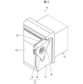
- FIG. 1 is a schematic perspective view of a cutting tool 10 according to an embodiment of the present disclosure.
- FIG. 2 is an enlarged view of part II in FIG.
- the cutting tool 10 is a turning tool used for turning among the cutting of the work material W (see FIG. 14).
- the cutting of the work material W includes outer diameter machining, inner diameter machining, grooving, cut-off machining, and the like.
- the cutting tool 10 may also have a holder 12 mounted on a lathe tool post and a cutting insert 14 held by the holder 12 .
- the holder 12 may be in the shape of a square bar extending from the front end 12a, which is the first end, to the rear end 12b, which is the second end.
- the holder 12 may have a bar shape other than a square bar shape such as a round bar shape. Examples of materials for the holder 12 include metals such as stainless steel, carbon steel, cast iron, and aluminum alloys.
- a pocket 16 for holding the cutting insert 14 may be located on the tip 12a side of the holder 12 .
- the length of the holder 12 may be set to 100 mm to 400 mm, for example.
- An injection port 18 for injecting coolant (cooling medium) toward the cutting insert 14 may be provided on the tip 12 a side of the holder 12 .
- the coolant is made of, for example, a water-insoluble oil agent or a water-soluble oil agent, and can be appropriately selected according to the material of the work material W to be used.
- water-insoluble oils include oil-based, inert extreme-pressure and active extreme-pressure cutting oils.
- water-soluble oils include cutting oils such as emulsions, solubles, and solutions.
- the coolant is not limited to a liquid, and may be a gas such as an inert gas.
- the cutting insert 14 may be positioned in the pocket 16 of the holder 12.
- the cutting insert 14 may be secured in the pocket 16 of the holder 12 by a locking screw 20 .
- the cutting insert 14 may be fixed in the pocket 16 of the holder 12 by a clamping member instead of the fixing screw 20 .
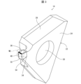
- FIG. 3 is a schematic perspective view of a cutting insert 14 according to an embodiment of the present disclosure.
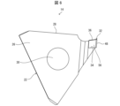
- 4 is a schematic top view of the cutting insert 14 shown in FIG. 3.
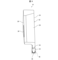
- FIG. 5 is a schematic right side view of the cutting insert 14 shown in FIG. 3.
- FIG. 6 is a schematic left side view of the cutting insert 14 shown in FIG. 3.
- FIG. 7 is a schematic front view of the cutting insert 14 shown in FIG. 3.
- FIG. 3 is a schematic perspective view of a cutting insert 14 according to an embodiment of the present disclosure.
- 4 is a schematic top view of the cutting insert 14 shown in FIG. 3.
- FIG. 5 is a schematic right side view of the cutting insert 14 shown in FIG. 3.
- FIG. 6 is a schematic left side view of the cutting insert 14 shown in FIG. 3.
- FIG. 7 is a schematic front view of the cutting insert 14 shown in FIG. 3.
- FIG. 3 is a schematic perspective view of a cutting insert 14 according to an embodiment of the present disclosure.
- 4 is a schematic top view of
- the cutting insert 14 may have a base portion 22 for mounting in the pocket 16 of the holder 12 .
- the base portion 22 may have a substantially polygonal first main surface 24 such as a substantially triangular shape, and a second main surface 26 opposite to the first main surface 24 .
- the first principal surface 24 and the second principal surface 26 may each be substantially polygonal, such as substantially triangular.
- the base portion 22 may have a substantially polygonal plate shape such as a substantially triangular plate shape.
- the base portion 22 may have a plurality of sides located between the first major surface 24 and the second major surface 26 , any of the plurality of sides may be a planar upper substrate surface 28 . .
- the base portion 22 may have a through-hole 30 for inserting the fixing screw 20 in its central portion.
- the through hole 30 may be opened on the first main surface 24 side and the second main surface 26 side.
- the cutting insert 14 may have a cutting portion 32 that contacts the workpiece W to perform cutting.
- the cutting portion 32 may be provided only at one of the plurality of corners of the base portion 22 .
- the cutting portion 32 may be provided at each of a plurality of corners of the base portion 22 .
- the cutting portion 32 may be provided in a notch portion 34 provided at a corner portion of the base portion 22 .
- Examples of the material of the base portion 22 include cemented carbide, cermet, and the like.
- Compositions of cemented carbide include, for example, WC--Co, WC--TiC--Co and WC--TiC--TaC--Co.
- WC—Co is produced by adding cobalt (Co) powder to tungsten carbide (WC) and sintering it.
- WC-TiC-Co is obtained by adding titanium carbide (TiC) to WC-Co.
- WC--TiC--TaC--Co is obtained by adding tantalum carbide (TaC) to WC--TiC--Co.
- a cermet is a sintered composite material in which a metal is combined with a ceramic component. Specific examples of cermets include those containing titanium compounds such as titanium carbide (TiC) and titanium nitride (TiN) as main components.
- Examples of materials for the cutting portion 32 include hard materials such as cBN (Cubic Boron Nitride) and PCD (PolyCrystalline Diamond). If the material of the cutting portion 32 is different from that of the base portion 22, the cutting portion 32 may be joined to the base portion 22 with brazing material. If the material of the cutting portion 32 is the same as the material of the base portion 22 , the cutting portion 32 may be integrally formed with the base portion 22 .
- the surface of the cutting insert 14 may be coated with a coating using a chemical vapor deposition (CVD) method or a physical vapor deposition (PVD) method.
- CVD chemical vapor deposition
- PVD physical vapor deposition
- materials for the coating include titanium carbide (TiC), titanium nitride (TiN), titanium carbonitride (TiCN), and alumina (Al 2 O 3 ).
- FIG. 8 is an enlarged view of section VIII in FIG. 3 and is a schematic enlarged perspective view of a portion of the cutting insert 14 according to the embodiment of the present disclosure.
- FIG. 9 is a schematic enlarged top view of a portion of a cutting insert 14 according to an embodiment of the present disclosure.
- the cutting portion 32 of the cutting insert 14 may have an upper surface 36, which may function as a rake surface for channeling chips.
- Top surface 36 of cutting portion 32 along with substrate top surface 28 of substrate portion 22 , may form the top surface of cutting insert 14 .
- the upper surface 36 of the cutting portion 32 may have a first corner 38 , a second corner 40 , and a first side 42 connected to the first corner 38 and the second corner 40 .
- First corner 38 and second corner 40 may each have a curved shape.
- the first side 42 may be linear or slightly curved. The fact that the first side 42 is slightly curved means that the first side 42 is not limited to a strictly linear shape. Therefore, when the first side 42 is slightly curved, the radius of curvature of the first side 42 is ten times or more the radius of curvature of the first corner 38 and the second corner 40. Macroscopically, the first side 42 may be considered to have a linear shape compared to the corner 40 .
- the top surface 36 of the cutting portion 32 may also have a second side 44 connected to the first corner 38 and a third side 46 connected to the second corner 40 .
- the second side 44 and the third side 46 may be parallel.
- the second side 44 and the third side 46 may gradually approach as they move away from the first side 42 .
- the cutting portion 32 may have a front side surface 48 connected to the first side 42, and the front side surface 48 may function as a flank.
- the cutting portion 32 may have a first corner side 50 connected to the front side 48 and the first corner 38 and a second corner side 52 connected to the front side 48 and the second corner.
- the first corner side 50 and the second corner side 52 may each function as a flank.
- the first corner side 50 and the second corner side 52 may each have a width that narrows away from the top surface 36 .
- the cutting portion 32 has a first lateral side 54 connected to the first corner side 50 and the second side 44 and a second lateral side 56 connected to the second corner side 52 and the third side 46 .
- the first lateral side 54 and the second lateral side 56 may each function as a flank.
- the cutting portion 32 may have a front cutting edge FB located on the first side 42 where the upper surface 36 and the front side surface 48 intersect.
- the end cutting edge FB may be located on the entire area of the first side 42 or a part of the area.
- the cutting portion 32 may also have a first corner cutting edge CB1 located at a first corner 38 that is the intersection of the top surface 36 and the first corner side surface 50 .
- the first corner cutting edge CB1 may be positioned on the entire or partial area of the first corner 38 .
- the cutting portion 32 may have a second corner cutting edge CB2 located at the second corner 40 which is the intersection of the top surface 36 and the second corner side surface 52 .
- the second corner cutting edge CB2 may be positioned on the entire or partial area of the second corner 40 .
- the cutting portion 32 may have a first side edge SB1 located on the second side 44, which is the intersection of the upper surface 36 and the first lateral side surface 54.
- the first side blade SB1 may be positioned on the entire area of the second side 44 or on a partial area.
- the first side edge SB1 may have the function of finishing the surface of the workpiece W to be machined.
- the first side edge SB1 may be omitted from the cutting portion 32 to avoid interference between the second side 44 and the machining surface of the workpiece W.
- the cutting portion 32 may have a second side edge SB2 located on the third side 46 where the top surface 36 and the second side surface 56 intersect.
- the second side cutting edge SB2 may be located on the entire area of the third side 46 or on a part of the area.
- the second side edge SB2 may have a function of finishing the machined surface of the material W to be cut.
- the second side edge SB2 may be omitted from the cutting portion 32 to avoid interference between the third side 46 and the machining surface of the work
- the upper surface 36 of the cutting portion 32 may have a front land surface 58 for increasing the strength of the end cutting edge FB.
- a front land surface 58 may be located at the outer edge of the upper surface 36 of the cutting portion 32 and extend along the front cutting edge FB.
- the front land surface 58 may be connected to the front cutting edge FB.
- the upper surface 36 of the cutting portion 32 may have a first corner land surface 60 for increasing the strength of the first corner cutting edge CB1.
- the first corner land surface 60 may be located at the outer edge of the upper surface 36 of the cutting portion 32 and extend along the first corner cutting edge CB1.
- the first corner land surface 60 may be connected to the first corner cutting edge CB1.
- the upper surface 36 of the cutting portion 32 may have a second corner land surface 62 for increasing the strength of the second corner cutting edge CB2.
- the second corner land surface 62 may be located at the outer edge of the upper surface 36 of the cutting portion 32 and extend along the second corner cutting edge CB2.
- the second corner land surface 62 may be connected to the second corner cutting edge CB2.
- the upper surface 36 of the cutting portion 32 may have a first horizontal land surface 64 for increasing the strength of the first side edge SB1.
- the first lateral land surface 64 may be located at the outer edge of the upper surface 36 of the cutting portion 32 and extend along the first side edge SB1.
- the first lateral land surface 64 may be connected to the first side blade SB1.
- the upper surface 36 of the cutting portion 32 may have a second horizontal land surface 66 for increasing the strength of the second side edge SB2.
- the second lateral land surface 66 may be located at the outer edge of the upper surface 36 of the cutting portion 32 and extend along the second side edge SB2.
- the second lateral land surface 66 may be connected to the second side cutting edge SB2.
- the front land surface 58, the first corner land surface 60, the second corner land surface 62, the first lateral land surface 64, and the second lateral land surface 66 each have a width of 0.03 mm to 0.03 mm when viewed from above. It may be set as a strip-shaped area of about 0.5 mm.
- the upper surface 36 of the cutting portion 32 may have a flat upper end surface 68 located on the base portion 22 side.
- the top surface 36 of the cutting portion 32 may have a raised wall surface 70 located between the outer edge of the top surface 36 and the top surface 68 .
- the rising wall surface 70 may be inclined with respect to the upper end surface 68, and may have a function of curling chips to improve chip dischargeability.
- the upper surface 36 of the cutting portion 32 may have a front groove 72 extending inward from the front land surface 58 side toward the center of the upper surface 36 .
- the front groove 72 may have a function as a coolant reservoir (gap) for accumulating coolant.
- the front groove 72 may be spaced from the front land surface 58 and the front cutting edge FB.
- the front groove 72 may be connected to the front land surface 58 instead of being spaced from the front land surface 58 .
- the front groove 72 may be connected to the rising wall surface 70 . Also, the front groove 72 may be connected to the upper end surface 68 . Chips are likely to come into contact with the rising wall surface 70 , while chips are less likely to come into contact with the upper end face 68 . Therefore, when the front groove 72 is connected to the upper end surface 68 , coolant tends to flow into the front groove 72 from the upper end surface 68 . As a result, the coolant tends to accumulate in the front grooves 72 .
- the number of front grooves 72 is plural in the examples of FIGS. 8 and 9, it may be one.
- the plurality of front grooves 72 consist of a first front groove 72A and a second front groove 72B located closer to the first corner 38 than the first front groove 72A. may have.
- the length of the first front groove 72A may be the same as the length of the second front groove 72B.
- the upper surface 36 of the cutting portion 32 may have a first corner groove 74 extending inward from the first corner land surface 60 side.
- the first corner groove 74 may function as a coolant reservoir that stores coolant.
- the first corner groove 74 may be spaced apart from the first corner land surface 60 and the first corner cutting edge CB1.
- the first corner groove 74 may be connected to the first corner land surface 60 instead of being spaced apart from the first corner land surface 60 .
- the first corner groove 74 may be connected to the rising wall surface 70 . Also, the first corner groove 74 may be connected to the upper end surface 68 . When the first corner groove 74 is connected to the upper end surface 68 , coolant tends to flow into the first corner groove 74 from the upper end surface 68 . As a result, coolant tends to accumulate in the first corner grooves 74 . Although the number of the first corner grooves 74 is one in the examples of FIGS. 8 and 9, it may be plural.
- the first corner groove 74 may extend inward from the boundary between the front land surface 58 and the first corner land surface 60 .
- the first corner groove 74 is remote from the boundary between the front land surface 58 and the first corner land surface 60, but may be connected to that boundary.
- the first corner groove 74 may extend parallel to the front groove 72 .
- the length of the first corner groove 74 may be shorter than the length of the front groove 72 .
- the width of the first corner groove 74 may be narrower than the width of the front groove 72 .
- the depth of the first corner groove 74 may be the same as the depth of the front groove 72 .
- the upper surface 36 of the cutting portion 32 may have a second corner groove 76 extending inward from the second corner land surface 62 side.
- the second corner groove 76 may function as a coolant reservoir.
- the second corner groove 76 may be spaced from the second corner land surface 62 and the second corner cutting edge CB2.
- the second corner groove 76 may be connected to the second corner land surface 62 instead of being spaced apart from the second corner land surface 62 .
- the second corner groove 76 may be connected to the rising wall surface 70 . Also, the second corner groove 76 may be connected to the upper end surface 68 . When the second corner groove 76 is connected to the upper end surface 68 , coolant tends to flow into the second corner groove 76 from the upper end surface 68 . As a result, coolant tends to accumulate in the second corner grooves 76 . Although the number of the second corner grooves 76 is one in the examples of FIGS. 8 and 9, it may be plural.
- the second corner groove 76 may extend inward from the boundary between the front land surface 58 and the second corner land surface 62 .
- the second corner groove 76 is remote from the boundary between the front land surface 58 and the second corner land surface 62, but may be connected to that boundary.
- the second corner groove 76 may extend parallel to the front groove 72 .
- the length of the second corner groove 76 may be shorter than the length of the front groove 72 .
- the width of the second corner groove 76 may be narrower than the width of the front groove 72 .
- the depth of the second corner groove 76 may be the same as the depth of the front groove 72 .
- the upper surface 36 of the cutting portion 32 may have a first lateral groove 78 extending inward from the first lateral land surface 64 side.
- the first lateral groove 78 may function as a coolant reservoir.
- the first lateral groove 78 may be separated from the first lateral land surface 64 and the first side edge SB1.
- the first lateral groove 78 may be connected to the first lateral land surface 64 .
- the first lateral groove 78 may be connected to the rising wall surface 70 . Also, the first lateral groove 78 may be connected to the upper end surface 68 . When the first lateral grooves 78 are connected to the upper end surface 68 , coolant tends to flow into the first lateral grooves 78 from the upper end surface 68 . As a result, coolant tends to accumulate in the first lateral grooves 78 .
- the length of the first lateral grooves 78 may be longer than the length of the first corner grooves 74 . Although the number of the first lateral grooves 78 is plural in the examples of FIGS. 8 and 9, it may be one.
- the upper surface 36 of the cutting portion 32 may have a second lateral groove 80 extending inward from the second lateral land surface 66 side.
- the second lateral groove 80 may function as a coolant reservoir.
- the second lateral groove 80 may be separated from the second lateral land surface 66 and the second side edge SB2.
- the second lateral groove 80 may be connected to the second lateral land surface 66 .
- the second lateral groove 80 may be connected to the rising wall surface 70 . Also, the second lateral groove 80 may be connected to the upper end surface 68 . When the second lateral grooves 80 are connected to the upper end surface 68 , coolant tends to flow into the second lateral grooves 80 from the upper end surface 68 . As a result, coolant tends to accumulate in the second lateral grooves 80 .
- the length of the second lateral grooves 80 may be longer than the length of the second corner grooves 76 . Although the number of the second lateral grooves 80 is plural in the examples of FIGS. 8 and 9, it may be one.
- the cross-sectional shape along the width direction of the front groove 72, the first corner groove 74, the second corner groove 76, the first lateral groove 78, and the second lateral groove 80 may be V-shaped or rectangular.
- the lengths of the front groove 72, first corner groove 74, second corner groove 76, first lateral groove 78, and second lateral groove 80 may be set to, for example, 0.3 mm to 3 mm.
- the widths of the front groove 72, first corner groove 74, second corner groove 76, first lateral groove 78, and second lateral groove 80 may be set to, for example, 0.05 mm to 0.5 mm.
- the depths of the front grooves 72, the first corner grooves 74, the second corner grooves 76, the first lateral grooves 78, and the second lateral grooves 80 may be set to, for example, 0.05 mm to 0.5 mm.
- a larger cutting load is applied to the first corner cutting edge CB1 than the end cutting edge FB. Cracks are likely to occur at the one-corner cutting edge CB1.
- the strength of the first corner cutting edge CB1 is increased, Cracks are less likely to occur in the first corner cutting edge CB1.
- the cooling effect of the coolant on the end cutting edge FB and the first corner cutting edge CB1 is enhanced, while the durability of the first corner cutting edge CB1, in other words, the cutting insert 14 durability can be improved.
- the depth of the first corner groove 74 is the same as the depth of the front groove 72 as in the examples shown in FIGS. can be done. Thereby, the cooling effect of the first corner cutting edge CB1 by the coolant can be further enhanced. If the depths of the front grooves 72 and the first corner grooves 74 are not constant, the maximum depth of the front grooves 72 and the maximum depth of the first corner grooves 74 may be compared. That the depth of the first corner groove 74 is the same as the depth of the front groove 72 does not strictly mean that they are the same. If the depth of the first corner groove 74 is about 97% to 103% of the depth of the front groove 72, it may be regarded as the same.
- the front cutting edge BF or the first corner cutting edge CB1 is likely to deteriorate around the boundary between the first side 42 and the first corner 38 on the upper surface 36 of the cutting portion 32 .
- the first corner groove 74 extends inward from the boundary between the front land surface 58 and the first corner land surface 60 as in the examples shown in FIGS. Coolant can be supplied efficiently.
- the end cutting edge BF or the first corner cutting edge CB1 is less likely to deteriorate, and the durability of the cutting insert 14 is improved. can be improved.
- the first corner groove 74 extends parallel to the front groove 72, the gap between the first corner groove 74 and the front groove 72 is prevented from becoming locally small, and the durability of the cutting insert 14 is improved. can be further improved.
- the length of the first front groove 72A is the same as the length of the second front groove 72B, as in the examples shown in FIGS. can be made smaller. Thereby, the durability of the first corner cutting edge CB1, in other words, the durability of the cutting insert 14 can be further improved.
- FIG. 10 is a schematic enlarged perspective view of part of a cutting insert 14A according to Modification 1 of the embodiment of the present disclosure.
- the cutting insert 14A according to Modification 1 of the embodiment of the present disclosure has the same configuration as the cutting insert 14 except for a part.
- the points that differ from the configuration of the cutting insert 14 will be described.
- members having the same functions as the members explained in the embodiment are denoted by the same reference numerals.
- the upper surface 36 of the cutting portion 32 may have two first corner grooves 74 extending inward from the first corner land surface 60 side.
- One first corner groove 74 may extend inward from the boundary between the front land surface 58 and the first corner land surface 60 .
- the other first corner groove 74 may extend inward from the central portion side of the first corner land surface 60 .
- the upper surface 36 of the cutting portion 32 may have two second corner grooves 76 extending inward from the second corner land surface 62 side.
- One of the second corner grooves 76 may extend inward from the boundary between the front land surface 58 and the second corner land surface 62 .
- the other second corner groove 76 may extend inward from the central portion side of the second corner land surface 62 .
- FIG. 11 is a schematic enlarged perspective view of part of a cutting insert 14B according to Modification 2 of the embodiment of the present disclosure.
- the cutting insert 14B according to Modification 2 of the embodiment of the present disclosure has the same configuration as the cutting insert 14 except for a part.
- the points that differ from the configuration of the cutting insert 14 will be described.
- members having the same functions as the members explained in the embodiment are denoted by the same reference numerals.
- the upper surface 36 of the cutting portion 32 may have one first lateral groove 78 extending inward from the first lateral land surface 64 side.
- the first lateral groove 78 may extend inward from the side of the boundary between the first lateral land surface 64 and the first corner land surface 60 .
- the upper surface 36 of the cutting portion 32 may have one second lateral groove 80 extending inward from the second lateral land surface 66 side.
- the second lateral groove 80 may extend inward from the side of the boundary between the second lateral land surface 66 and the first corner land surface 60 .
- each of the first corner side 50 and the second corner side 52 may become narrower with increasing distance from the upper surface 36 .
- FIG. 12 is a schematic enlarged perspective view of part of a cutting insert 14C according to Modification 3 of the embodiment of the present disclosure.
- the cutting insert 14C according to Modification 3 of the embodiment of the present disclosure has the same configuration as the cutting insert 14B except for a part.
- the points that differ from the configuration of the cutting insert 14B will be described.
- members having the same functions as the members explained in Modification 2 of the embodiment are denoted by the same reference numerals.
- the plurality of front grooves 72 may have a first front groove 72A and a second front groove 72B positioned closer to the first corner 38 than the first front groove 72A.
- the length of the first front groove 72A may be longer than the length of the second front groove 72B.
- FIG. 13 is a schematic enlarged perspective view of part of a cutting insert 14D according to Modification 4 of the embodiment of the present disclosure.
- the cutting insert 14D according to Modification 4 of the embodiment of the present disclosure has the same configuration as the cutting insert 14C except for a part.
- the points that differ from the configuration of the cutting insert 14C will be described.
- members having the same functions as the members explained in Modification 3 of the embodiment are denoted by the same reference numerals.
- the upper surface 36 of the cutting portion 32 may have a plurality of first lateral grooves 78 extending inward from the first lateral land surface 64 side.
- One first lateral groove 78 may extend inward from the side of the boundary between the first lateral land surface 64 and the first corner land surface 60 .
- the upper surface 36 of the cutting portion 32 may have a plurality of second lateral grooves 80 extending inward from the second lateral land surface 66 side.
- One second lateral groove 80 may extend inward from the side of the boundary between the second lateral land surface 66 and the first corner land surface 60 .
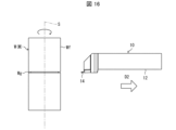
- FIGS. 14 to 16 are schematic diagrams for explaining the method for manufacturing a cut product according to the embodiment.
- the method for manufacturing a cut workpiece according to the embodiment is a method for manufacturing a cut workpiece M, which is a workpiece W that has been machined.
- the first step is a step of rotating the work material W around its axis S.
- the second step is the step of bringing the cutting insert 14 of the cutting tool 10 into contact with the rotating work W.
- the third step is the step of separating the cutting tool 10 from the work material W.
- Examples of the material of the work material W include stainless steel, carbon steel, alloy steel, cast iron, and non-ferrous metals.
- the cutting tool 10 is mounted on the turret of the lathe, and the work material W is mounted on the chuck of the lathe.
- the chuck is rotated to rotate the workpiece W around its axis S (first step).
- the cutting tool 10 is brought closer to the work W, and the cutting insert 14 is applied to the outer peripheral surface Wf of the rotating work W.
- the part 32 is brought into contact with the workpiece W to give a cut (second step).
- the work material W is cut, and the work groove Wg can be formed in the outer peripheral surface Wf of the work material W.
- the cutting tool 10 is separated from the work material W by moving the cutting tool 10 in the direction of the arrow D2 (third step).
- the cutting of the work material W is completed, and the machined product M, which is the work material W that has been cut, can be manufactured. Since the cutting insert 14 has excellent cutting ability for the reason described above, it is possible to manufacture a machined workpiece M with excellent machining accuracy.
- the cutting portion 32 of the cutting insert 14 may be repeatedly brought into contact with different portions of the work W while the work W is being rotated.
- the cutting tool 10 is brought closer to the work material W, but since the cutting tool 10 and the work material W should be relatively brought closer, for example, the work material W is brought closer to the cutting tool 10 may In this respect, when the cutting tool 10 is separated from the work material W, the same operation is performed.
- the front land surface 58, the first corner land surface 60, the second corner land surface 62, the first lateral land surface 64, and the second lateral land surface 66 may each be honed surfaces formed by so-called honing.
- the rising wall surface 70 may be used as a land surface. In such a case, it is possible to distinguish between the honing surface having a curved surface shape and the land surface having a planar shape.
Landscapes
- Engineering & Computer Science (AREA)
- Mechanical Engineering (AREA)
- Milling Processes (AREA)
Priority Applications (3)
| Application Number | Priority Date | Filing Date | Title |
|---|---|---|---|
| JP2023561560A JP7630641B2 (ja) | 2021-11-17 | 2022-11-10 | 切削インサート、切削工具、及び切削加工物の製造方法 |
| CN202280075112.6A CN118234586A (zh) | 2021-11-17 | 2022-11-10 | 切削刀片、切削刀具及切削加工物的制造方法 |
| US18/710,614 US20250001507A1 (en) | 2021-11-17 | 2022-11-10 | Cutting insert, cutting tool, and method for manufacturing machined product |
Applications Claiming Priority (2)
| Application Number | Priority Date | Filing Date | Title |
|---|---|---|---|
| JP2021187312 | 2021-11-17 | ||
| JP2021-187312 | 2021-11-17 |
Publications (1)
| Publication Number | Publication Date |
|---|---|
| WO2023090247A1 true WO2023090247A1 (ja) | 2023-05-25 |
Family
ID=86396971
Family Applications (1)
| Application Number | Title | Priority Date | Filing Date |
|---|---|---|---|
| PCT/JP2022/041893 Ceased WO2023090247A1 (ja) | 2021-11-17 | 2022-11-10 | 切削インサート、切削工具、及び切削加工物の製造方法 |
Country Status (4)
| Country | Link |
|---|---|
| US (1) | US20250001507A1 (https=) |
| JP (1) | JP7630641B2 (https=) |
| CN (1) | CN118234586A (https=) |
| WO (1) | WO2023090247A1 (https=) |
Cited By (1)
| Publication number | Priority date | Publication date | Assignee | Title |
|---|---|---|---|---|
| WO2025074852A1 (ja) * | 2023-10-05 | 2025-04-10 | 京セラ株式会社 | 切削インサート、切削工具、および切削加工物の製造方法 |
Families Citing this family (1)
| Publication number | Priority date | Publication date | Assignee | Title |
|---|---|---|---|---|
| US20240261869A1 (en) * | 2021-06-06 | 2024-08-08 | Vargus Ltd | Cutting Insert |
Citations (3)
| Publication number | Priority date | Publication date | Assignee | Title |
|---|---|---|---|---|
| JP2002502711A (ja) * | 1998-02-03 | 2002-01-29 | サンドビック アクティエボラーグ | 冷却溝を備えた切削インサート |
| US20150063926A1 (en) * | 2013-08-30 | 2015-03-05 | Kennametal Inc. | Indexable cutting insert with coolant delivery |
| CN105750609A (zh) * | 2014-12-19 | 2016-07-13 | 重庆丰德数控机床有限公司 | 带有内冷辐射斜流道铣刀片 |
-
2022
- 2022-11-10 CN CN202280075112.6A patent/CN118234586A/zh active Pending
- 2022-11-10 WO PCT/JP2022/041893 patent/WO2023090247A1/ja not_active Ceased
- 2022-11-10 JP JP2023561560A patent/JP7630641B2/ja active Active
- 2022-11-10 US US18/710,614 patent/US20250001507A1/en active Pending
Patent Citations (3)
| Publication number | Priority date | Publication date | Assignee | Title |
|---|---|---|---|---|
| JP2002502711A (ja) * | 1998-02-03 | 2002-01-29 | サンドビック アクティエボラーグ | 冷却溝を備えた切削インサート |
| US20150063926A1 (en) * | 2013-08-30 | 2015-03-05 | Kennametal Inc. | Indexable cutting insert with coolant delivery |
| CN105750609A (zh) * | 2014-12-19 | 2016-07-13 | 重庆丰德数控机床有限公司 | 带有内冷辐射斜流道铣刀片 |
Cited By (1)
| Publication number | Priority date | Publication date | Assignee | Title |
|---|---|---|---|---|
| WO2025074852A1 (ja) * | 2023-10-05 | 2025-04-10 | 京セラ株式会社 | 切削インサート、切削工具、および切削加工物の製造方法 |
Also Published As
| Publication number | Publication date |
|---|---|
| JP7630641B2 (ja) | 2025-02-17 |
| CN118234586A (zh) | 2024-06-21 |
| US20250001507A1 (en) | 2025-01-02 |
| JPWO2023090247A1 (https=) | 2023-05-25 |
Similar Documents
| Publication | Publication Date | Title |
|---|---|---|
| JP7304989B2 (ja) | 切削インサート、切削工具及び切削加工物の製造方法 | |
| JP6861269B2 (ja) | 切削インサート、切削工具及び切削加工物の製造方法 | |
| CN111148590B (zh) | 切削刀片、切削刀具以及切削加工物的制造方法 | |
| EP1819469A1 (en) | Cutting insert with cutting tips anchor portions. | |
| CN107073594A (zh) | 刀架、切削工具以及切削加工物的制造方法 | |
| JP7630641B2 (ja) | 切削インサート、切削工具、及び切削加工物の製造方法 | |
| JP6462126B2 (ja) | 切削インサート、切削工具及びこれを用いた切削加工物の製造方法 | |
| CN115515740A (zh) | 钻头以及切削加工物的制造方法 | |
| JP7155407B2 (ja) | 切削インサート、切削工具及び切削加工物の製造方法 | |
| JP6691549B2 (ja) | ドリル用ホルダ、ドリル及び切削加工物の製造方法 | |
| US12011767B2 (en) | Cutting insert, cutting tool, and method for manufacturing machined product | |
| WO2025204502A1 (ja) | ドリルおよび切削加工物の製造方法 | |
| JPWO2019087656A1 (ja) | 切削工具及び切削加工物の製造方法 | |
| WO2024048257A1 (ja) | 切削インサート、切削工具、及び切削加工物の製造方法 | |
| JP6467048B2 (ja) | 切削工具及び切削加工物の製造方法 | |
| WO2023063183A1 (ja) | 切削インサート、切削工具及び切削加工物の製造方法 | |
| JP7045460B2 (ja) | 切削工具及び切削加工物の製造方法 | |
| WO2025074852A1 (ja) | 切削インサート、切削工具、および切削加工物の製造方法 | |
| JP7779820B2 (ja) | 切削インサート、切削工具及び切削加工物の製造方法 | |
| JP6825854B2 (ja) | 切削工具及び切削加工物の製造方法 | |
| WO2024062985A1 (ja) | 切削インサート、切削工具及び切削加工物の製造方法 | |
| WO2024202230A1 (ja) | 切削インサート、切削工具及び切削加工物の製造方法 | |
| JP7279163B2 (ja) | 回転工具及び切削加工物の製造方法 | |
| JP2025133477A (ja) | 切削インサート、切削工具及び切削加工物の製造方法 | |
| WO2025182455A1 (ja) | 切削インサート、切削工具及び切削加工物の製造方法 |
Legal Events
| Date | Code | Title | Description |
|---|---|---|---|
| 121 | Ep: the epo has been informed by wipo that ep was designated in this application |
Ref document number: 22895529 Country of ref document: EP Kind code of ref document: A1 |
|
| ENP | Entry into the national phase |
Ref document number: 2023561560 Country of ref document: JP Kind code of ref document: A |
|
| WWE | Wipo information: entry into national phase |
Ref document number: 202280075112.6 Country of ref document: CN |
|
| WWE | Wipo information: entry into national phase |
Ref document number: 18710614 Country of ref document: US |
|
| 122 | Ep: pct application non-entry in european phase |
Ref document number: 22895529 Country of ref document: EP Kind code of ref document: A1 |