WO2023090245A1 - 給電構造、板状体及び窓ガラス - Google Patents
給電構造、板状体及び窓ガラス Download PDFInfo
- Publication number
- WO2023090245A1 WO2023090245A1 PCT/JP2022/041889 JP2022041889W WO2023090245A1 WO 2023090245 A1 WO2023090245 A1 WO 2023090245A1 JP 2022041889 W JP2022041889 W JP 2022041889W WO 2023090245 A1 WO2023090245 A1 WO 2023090245A1
- Authority
- WO
- WIPO (PCT)
- Prior art keywords
- dielectric plate
- power supply
- conductor
- plate
- structure according
- Prior art date
- Legal status (The legal status is an assumption and is not a legal conclusion. Google has not performed a legal analysis and makes no representation as to the accuracy of the status listed.)
- Ceased
Links
Images




Classifications
-
- H—ELECTRICITY
- H01—ELECTRIC ELEMENTS
- H01Q—ANTENNAS, i.e. RADIO AERIALS
- H01Q1/00—Details of, or arrangements associated with, antennas
- H01Q1/12—Supports; Mounting means
- H01Q1/1271—Supports; Mounting means for mounting on windscreens
- H01Q1/1285—Supports; Mounting means for mounting on windscreens with capacitive feeding through the windscreen
-
- H—ELECTRICITY
- H01—ELECTRIC ELEMENTS
- H01P—WAVEGUIDES; RESONATORS, LINES, OR OTHER DEVICES OF THE WAVEGUIDE TYPE
- H01P5/00—Coupling devices of the waveguide type
- H01P5/08—Coupling devices of the waveguide type for linking dissimilar lines or devices
-
- H—ELECTRICITY
- H01—ELECTRIC ELEMENTS
- H01P—WAVEGUIDES; RESONATORS, LINES, OR OTHER DEVICES OF THE WAVEGUIDE TYPE
- H01P3/00—Waveguides; Transmission lines of the waveguide type
- H01P3/02—Waveguides; Transmission lines of the waveguide type with two longitudinal conductors
- H01P3/08—Microstrips; Strip lines
- H01P3/085—Triplate lines
-
- H—ELECTRICITY
- H01—ELECTRIC ELEMENTS
- H01Q—ANTENNAS, i.e. RADIO AERIALS
- H01Q1/00—Details of, or arrangements associated with, antennas
- H01Q1/12—Supports; Mounting means
- H01Q1/1271—Supports; Mounting means for mounting on windscreens
-
- H—ELECTRICITY
- H01—ELECTRIC ELEMENTS
- H01Q—ANTENNAS, i.e. RADIO AERIALS
- H01Q1/00—Details of, or arrangements associated with, antennas
- H01Q1/27—Adaptation for use in or on movable bodies
Definitions
- the present disclosure relates to a power supply structure, a plate-shaped body, and a window glass.
- Patent Document 1 a structure is known in which an antenna structure installed inside a composite glass plate is fed with a flat conductor (see Patent Document 1, for example).
- the conventional power supply structure is configured to pull out the flat conductor from the periphery of the composite glass plate, the wiring near the periphery of the composite glass may become complicated.
- the present disclosure provides a simple configuration capable of supplying power to conductors between a pair of dielectric plates.
- This disclosure is a first dielectric plate; a second dielectric plate facing the first dielectric plate; an intermediate film disposed between the first dielectric plate and the second dielectric plate; a conductor disposed between the first dielectric plate and the second dielectric plate; a power supply section disposed on the side opposite to the first dielectric plate with respect to the intermediate film and sandwiching at least one of a portion of the intermediate film and a portion of the second dielectric plate between the conductor and the conductor; , a first transmission line connected to the power feeding unit;
- the power feeding portion provides a power feeding structure that electromagnetically couples with the conductor at a distance thinner than the thickness of the first dielectric plate.
- the present disclosure also provides a plate-like body including the power supply structure and a window glass including the power supply structure.
- FIG. 2 is a partial cross-sectional view showing one configuration example of a plate-like body provided with the power supply structure of the first embodiment
- FIG. 11 is a partial cross-sectional view showing one configuration example of a plate-like body provided with the power supply structure of the second embodiment
- FIG. 11 is a partial cross-sectional view showing one configuration example of a plate-like body provided with the power supply structure of the third embodiment
- FIG. 12 is a partial cross-sectional view showing one configuration example of a plate-like body provided with the power supply structure of the fourth embodiment
- FIG. 12 is a partial cross-sectional view showing one configuration example of a plate-like body provided with the power supply structure of the fifth embodiment
- FIG. 20 is a partial cross-sectional view showing one configuration example of a plate-like body provided with the power supply structure of the sixth embodiment;
- FIG. 21 is a partial cross-sectional view showing one configuration example of a plate-like body provided with the power supply structure of the seventh embodiment;
- FIG. 20 is a partial cross-sectional view showing one configuration example of a plate-like body provided with the power supply structure of the eighth embodiment;
- FIG. 20 is a partial cross-sectional view showing one configuration example of a plate-like body provided with the power supply structure of the ninth embodiment;
- FIG. 20 is a partial cross-sectional view showing one configuration example of a plate-like body provided with the power supply structure of the tenth embodiment;
- FIG. 11 is a plan view showing a first configuration example of recesses in the power supply structures of the fifth to tenth embodiments;
- FIG. 11 is a plan view showing a second configuration example of recesses in the power supply structures of the fifth to tenth embodiments;
- FIG. 14 is a plan view showing a third configuration example of a concave portion in the power feeding structure of the fifth to tenth embodiments;
- the X-axis direction, Y-axis direction, and Z-axis direction represent directions parallel to the X-axis, directions parallel to the Y-axis, and directions parallel to the Z-axis, respectively.
- the X-axis direction, the Y-axis direction, and the Z-axis direction are orthogonal to each other.
- the XY plane, YZ plane, and ZX plane are virtual planes parallel to the X-axis direction and Y-axis direction, virtual planes parallel to the Y-axis direction and Z-axis direction, and virtual planes parallel to the Z-axis direction and X-axis direction, respectively.
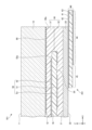
- FIG. 1 is a partial cross-sectional view showing one configuration example of a plate-like body provided with the power supply structure of the first embodiment.
- the plate-like body 111 shown in FIG. 1 includes a feeding structure 211 feeding the conductor 52 between the pair of dielectric plates 10 and 20 .
- the plate-like body 111 is a laminate including a pair of dielectric plates 10 and 20 .
- the pair of dielectric plates 10 and 20 are plate-like members whose main component is a dielectric.
- One or both of the pair of dielectric plates 10 and 20 may be glass plates.
- the dielectric plate 10 is a glass plate
- the dielectric plate 20 may be a dielectric plate different from the glass plate. may be different dielectric plates.
- the plate-like body 111 is also called laminated glass.
- both of the pair of dielectric plates 10 and 20 are glass plates, they may be glass plates of the same composition or glass plates of different compositions.
- the plate-like body 111 is, for example, a window glass for a vehicle.
- window glass for vehicles include a windshield attached to the front of the vehicle, a rear glass attached to the rear of the vehicle, a side glass attached to the side of the vehicle, and a roof glass attached to the ceiling of the vehicle.
- the vehicle window glass according to the present embodiment is not limited to these examples.
- the plate-like body 111 is a laminate comprising a pair of dielectric plates 10 and 20 , an intermediate film 30 and a conductor 52 .
- Feed structure 211 shares a pair of dielectric plates 10 and 20 , intermediate film 30 and conductor 52 with plate-like body 111 .
- the feeding structure 211 comprises a pair of dielectric plates 10 and 20 , an intermediate film 30 , a conductor 52 , a feeding section 45 and a transmission line 44 .
- the dielectric plate 10 is an example of a first dielectric plate.
- the dielectric plate 10 has a plate shape having a main surface 11 facing the positive side in the Z-axis direction and a main surface 12 facing the side opposite to the main surface 11 in the Z-axis direction (negative side in the Z-axis direction).
- is the dielectric of Dielectric plate 10 may be transparent or translucent.
- the plate-like body 111 is a window glass for a vehicle
- the main surface 11 is the surface on the outside of the vehicle
- the main surface 12 is the surface on the inside of the vehicle.
- the dielectric plate 20 is an example of a second dielectric plate facing the first dielectric plate.
- Dielectric plate 20 is arranged on main surface 12 side of dielectric plate 10 .
- the dielectric plate 20 is a plate-shaped dielectric having a principal surface 21 facing the positive side in the Z-axis direction and a principal surface 22 facing away from the principal surface 21 in the Z-axis direction.
- Dielectric plate 20 may be transparent or translucent.
- the plate-like body 111 is a window glass for a vehicle
- the main surface 21 is the surface on the outside of the vehicle
- the main surface 22 is the surface on the inside of the vehicle.
- the intermediate film 30 is a transparent or translucent dielectric placed between the dielectric plate 10 and the dielectric plate 20 .
- Dielectric plate 10 and dielectric plate 20 are bonded by intermediate film 30 .
- the material forming the intermediate film 30 include thermoplastic polyvinyl butyral (PVB), ethylene vinyl acetate copolymer (EVA), cycloolefin polymer (COP), and the like.
- PVB thermoplastic polyvinyl butyral
- EVA ethylene vinyl acetate copolymer
- COP cycloolefin polymer
- the dielectric constant of the intermediate film 30 is 2.4 or more and 3.5 or less.
- the plate-like body 111 may have a light shielding film 80 on at least one of the principal surfaces 12 , 21 and 22 .
- the light shielding film 80 may be arranged with a predetermined width from the edge of the plate-like body 111 (the edge 30a of the intermediate film 30).
- the light shielding film 80 may be arranged on the periphery of the vehicle window glass.
- the inner edge of the light shielding film 80 corresponds to the outer edge of the opening (transmission region) of the vehicle window glass.
- the light shielding film 80 is an opaque colored ceramic layer having a thickness of about 5 ⁇ m to 25 ⁇ m.
- the color of the light shielding film 80 is arbitrary, but dark colors such as black, brown, gray and dark blue, or white are preferable, and black is more preferable.
- the plate-like body 111 is provided with the light shielding film 80 , it overlaps with at least a part of the transmission line 44 , the power feeding portion 45 , and the conductor 52 , which will be described later, so that these are hardly visible.
- the conductor 52 is a linear or planar conductor arranged between the dielectric plate 10 and the dielectric plate 20 .
- Specific examples of the conductor 52 include signal lines, antenna elements, electrodes, and the like.
- FIG. 1 shows an example in which conductors 52 are formed on main surface 21 of dielectric plate 20 .
- the conductor 52 is formed on the conductive film coated on the main surface 21 by vapor deposition on the main surface 21 .
- the power feeding portion 45 is arranged on the side opposite to the dielectric plate 10 with respect to the intermediate film 30 , and is a portion that sandwiches part of the dielectric plate 20 with the conductor 52 .
- the transmission line 44 is an example of a first transmission line, and is connected to the feeding section 45 .
- the power feeding portion 45 and the transmission line 44 are formed on the substrate 40 .
- the substrate 40 is a plate-like component having a main surface parallel to the XY plane.
- the substrate 40 includes a dielectric layer 41 mainly composed of a dielectric, a signal line 42 formed on the surface of the dielectric layer 41 on the positive side in the Z-axis direction, and a signal line 42 formed on the surface of the dielectric layer 41 on the positive side in the Z-axis direction. and a ground layer 43 formed on the surface of the Substrate 40 may be a flexible substrate or a rigid substrate.
- the transmission line 44 is formed by at least the dielectric layer 41 , the signal line 42 and the ground layer 43 .
- the transmission line 44 transmits high frequency signals.
- a power feeder 45 is connected to one end of the transmission line 44 .
- a communication device (not shown) is electrically connected to the other end of the transmission line 44 .
- Specific examples of the transmission line 44 include microstripline, stripline, coplanar waveguide, GCPW (coplanar waveguide with ground plane), coplanar strip, slotline, waveguide, and the like.
- the transmission line 44 may be a coaxial cable.
- the inner conductor of the coaxial cable is connected to a connector provided on the feed section 45 .
- the power feeding portion 45 has a dielectric layer 41 formed with a conductor portion (hereinafter also referred to as "opposing conductor") facing the conductor 52 on the positive side in the Z-axis direction.
- the opposing conductor of the feeding portion 45 is connected to the end of the signal line 42 of the transmission line 44 .
- the opposing conductor of the power supply portion 45 protrudes from the edge of the ground layer 43 in plan view in the Z-axis direction.
- the opposing conductor of the feeding portion 45 is, for example, a linear conductor formed on the surface of the dielectric layer 41, and may be a single line segment or a bent line. Note that the opposing conductor of the feeding portion 45 may be a planar conductor formed on the surface of the dielectric layer 41 .
- the power feeding portion 45 is electromagnetically coupled with the conductor 52 at intervals thinner than the thickness of the dielectric plate 10 in the Z-axis direction. Since the conductor 52 and the opposing conductor of the feeding section 45 are close to each other within a distance that enables electromagnetic coupling, the feeding section 45 is not in contact with the conductor 52 enclosed in the pair of dielectric plates 10 and 20 by electromagnetic coupling. supply power.
- a simple power supply capable of supplying power to the conductor 52 between the pair of dielectric plates 10 and 20 by non-contact power supply by electromagnetic coupling even if the dielectric plate 20 is interposed between the conductor 52 and the power supply portion 45. Structure 211 can be implemented.
- the power supply structure 211 even if the end 52a of the conductor 52 is located inside (negative side in the X-axis direction) the end 30a of the intermediate film 30, the power supply from the power supply part 45 to the conductor 52 in the Z-axis direction Power can be supplied with a simple structure.
- the electromagnetic coupling distance is, for example, 500 ⁇ m or less, preferably 250 ⁇ m or less, more preferably 150 ⁇ m or less, even more preferably 100 ⁇ m or less, and most preferably 50 ⁇ m or less. In the case of FIG. 1, the electromagnetic coupling distance is approximately equal to the thickness of the dielectric plate 20 in the Z-axis direction.
- the dielectric plate 10 is preferably thicker than the dielectric plate 20 (glass plate 20).
- the thickness of the glass plate 10 may be, for example, about 3.2 mm.
- the composition of the material constituting the dielectric plate 20 (glass plate 20) can be appropriately selected.
- tempered glass is used as a glass plate having a thickness that allows electromagnetic coupling and a predetermined strength as described above. It is preferable to use Examples of tempered glass include air-cooled tempered glass and chemically tempered glass. If the thickness of the tempered glass is thin, it is preferable to use chemically tempered glass.
- the glass plate 20 When the glass plate 20 is chemically strengthened glass, the glass plate 20 may have a composition that can be strengthened by molding and chemical strengthening treatment.
- glass sheets that can be chemically strengthened include aluminosilicate glass, soda lime glass, borosilicate glass, lead glass, alkali barium glass, and aluminoborosilicate glass.
- the power supply structure 211 supplies power by non-contact power supply using electromagnetic coupling, so it is suitable for power supply to the conductor 52 through which a high-frequency signal having a frequency in a relatively high band passes.
- the dielectric loss tangent (tan ⁇ ) of the dielectric plate 20 (glass plate 20) is preferably low.
- tan ⁇ of the glass plate 20 at a frequency of 10 GHz is preferably 0.010 or less, more preferably 0.009 or less.
- the conductor 52 or an antenna connected to the conductor 52 is configured to be capable of transmitting and receiving radio waves in a predetermined frequency band.
- the predetermined frequency band is a relatively high band of 300 MHz to 3 GHz UHF (Ultra High Frequency) band, 3 GHz to 30 GHz SHF (Super High Frequency) band, or 30 GHz to 300 GHz EHF (Extremely High Frequency) band.
- Specific examples of such high frequency bands include bands used in the fifth generation communication (5G) standards (frequency bands below 6 GHz (sub6), frequency bands above 24 GHz (28 GHz band, 39 GHz band, etc.)). be done.
- 5G fifth generation communication
- ⁇ be the wavelength in air of radio waves transmitted and received by the conductor 52 or an antenna (for example, an antenna 70 described later) connected to the conductor 52
- k be the wavelength shortening rate of the surrounding medium of the feeding section 45 .
- the opposing conductor of the feeding portion 45 is a linear conductor having a line length L of ⁇ /4
- the electromagnetic coupling with the conductor 52 is strengthened, and loss due to non-contact feeding is suppressed.
- 0.80 ⁇ k ⁇ /4 ⁇ L ⁇ 1.20 ⁇ k ⁇ /4 If 0.90 ⁇ k ⁇ /4 ⁇ L ⁇ 1.10 ⁇ k ⁇ /4 is preferably 0.95 ⁇ k ⁇ /4 ⁇ L ⁇ 1.05 ⁇ k ⁇ /4 is more preferable.
- FIG. 2 is a partial cross-sectional view showing one configuration example of a plate-like body provided with the power supply structure of the second embodiment.
- the plate 112 shown in FIG. 2 comprises a feed structure 212 feeding the conductor 52 between the pair of dielectric plates 10,20.
- FIG. 2 shows an example in which the conductor 52 is formed on the main surface 12 of the dielectric plate 10.
- the conductor 52 is formed in the conductive film coated on the main surface 12 by vapor deposition on the main surface 12 .
- the power supply portion 45 is a portion that sandwiches a portion of the intermediate film 30 and a portion of the dielectric plate 20 between the conductor 52 and the conductor 52 .
- the power supply part 45 electromagnetically couples with the conductor 52 at intervals thinner than the thickness of the dielectric plate 10 in the Z-axis direction, and supplies power to the conductor 52 in a non-contact manner through electromagnetic coupling.
- the simple power supply structure 212 is capable of supplying power to the conductor 52 between the pair of dielectric plates 10 and 20. can be realized.
- the electromagnetic coupling distance is substantially equal to the sum of the thickness of the intermediate film 30 in the Z-axis direction and the thickness of the dielectric plate 20 in the Z-axis direction.
- FIG. 3 is a partial cross-sectional view showing one configuration example of a plate-like body provided with the power supply structure of the third embodiment.
- the plate-like body 113 shown in FIG. 3 comprises a feeding structure 213 feeding the conductor 52 between the pair of dielectric plates 10,20.
- FIG. 3 shows an example in which the conductor 52 is sandwiched between the intermediate films 31 and 32 .
- the intermediate film 31 is an example of a first intermediate film included in the intermediate film 30 .
- the intermediate film 32 is an example of a second intermediate film included in the intermediate film 30 .
- the conductor 52 is sandwiched between the intermediate film 31 in contact with the main surface 12 of the dielectric plate 10 and the intermediate film 32 in contact with the main surface 21 of the dielectric plate 20 .
- the power supply portion 45 is a portion that sandwiches a portion of the intermediate film 32 and a portion of the dielectric plate 20 with the conductor 52 .
- the power supply part 45 electromagnetically couples with the conductor 52 at intervals thinner than the thickness of the dielectric plate 10 in the Z-axis direction, and supplies power to the conductor 52 in a non-contact manner through electromagnetic coupling.
- the simple power feeding structure 213 is capable of feeding power to the conductor 52 between the pair of dielectric plates 10 and 20. can be realized.
- the electromagnetic coupling distance is substantially equal to the sum of the thickness of the intermediate film 32 in the Z-axis direction and the thickness of the dielectric plate 20 in the Z-axis direction.
- FIG. 4 is a partial cross-sectional view showing one configuration example of a plate-like body provided with the power supply structure of the fourth embodiment.
- a plate-like body 101 shown in FIG. 4 includes a feeding structure 201 feeding a conductor 52 of a transmission line 50 between a pair of dielectric plates 10 and 20 .
- the plate-like body 101 is a laminate comprising a pair of dielectric plates 10 and 20, an intermediate film 30, and a transmission line 50.
- the feeding structure 201 shares the pair of dielectric plates 10 and 20 , the intermediate film 30 and the transmission line 50 with the plate-like body 101 .
- the feeding structure 201 comprises a pair of dielectric plates 10 and 20 , an intermediate film 30 , a transmission line 50 , a feeding portion 45 and a transmission line 44 .
- the intermediate film 30 includes an intermediate film 31 and an intermediate film 32 .
- Intermediate film 31 is an example of a first intermediate film and is interposed between dielectric plate 10 and transmission line 50 .
- the intermediate film 32 is an example of a second intermediate film and is interposed between the dielectric plate 20 and the transmission line 50 .
- the transmission line 50 is an example of a second transmission line, and is sandwiched between the intermediate films 31 and 32 .
- the transmission line 50 includes a dielectric layer 51 containing a dielectric as a main component, a conductor 52 formed on the positive surface of the dielectric layer 51 in the Z-axis direction, and a negative surface of the dielectric layer 51 in the Z-axis direction. and a ground layer 53 formed on the surface of the A conductor 52 is a signal line of the transmission line 50 .
- the transmission line 50 transmits high frequency signals.
- One end of the transmission line 50 faces the power feeder 45 in the Z-axis direction.
- the other end of transmission line 50 is electrically connected to antenna 70 .
- the conductor 52 of the transmission line 50 is fed from the feeding section 45 through the slot 54 formed in the ground layer 53 .
- the antenna 70 is a linear or planar conductor arranged between the pair of dielectric plates 10 and 20, and is connected to the conductor 52 at the other end of the transmission line 50 in the same layer.
- Antenna 70 transmits and receives radio waves to and from the outside of plate-like body 101 .
- Antenna 70 may be transparent or opaque. If the antenna 70 is transparent, the antenna 70 becomes less visible when the plate-shaped body is configured as a vehicle window glass. In particular, when the plate-like body 101 (vehicle window glass) has the light-shielding film 80 described in the first embodiment, the antenna 70, if transparent, is an opening (light-shielding film) away from the edge of the plate-like body 101. Even if it is arranged in the transmission region inside the inner edge of the membrane 80, it is difficult for the passenger to visually recognize it.
- the power supply part 45 electromagnetically couples with the conductor 52 at intervals thinner than the thickness of the dielectric plate 10 in the Z-axis direction, and supplies power to the conductor 52 in a non-contact manner through electromagnetic coupling.
- a simple power supply structure 201 can be realized.
- the electromagnetic coupling distance is substantially equal to the sum of the thickness of the dielectric layer 51 in the Z-axis direction, the thickness of the intermediate film 32 in the Z-axis direction, and the thickness of the dielectric plate 20 in the Z-axis direction.
- FIG. 5 is a partial cross-sectional view showing one configuration example of a plate-like body provided with the power supply structure of the fifth embodiment.
- the plate-like body 102 shown in FIG. 5 includes a feeding structure 202 feeding the conductor 52 of the transmission line 50 between the pair of dielectric plates 10 and 20 .
- FIG. 5 shows an example in which the dielectric plate 20 has recesses 23 .
- the recess 23 is a hole that is formed in the dielectric plate 20 as an opening that is recessed on the positive side in the Z-axis direction with respect to the main surface 22 and that does not penetrate the dielectric plate 20 .
- the power feeding portion 45 is arranged in the concave portion 23 .
- the power supply portion 45 is positioned in the recess 23, so that a distance that enables electromagnetic coupling between the power supply portion 45 and the conductor 52 can be ensured. Therefore, a simple power supply structure 202 capable of supplying power to the conductor 52 between the pair of dielectric plates 10 and 20 can be realized.
- the glass composition of the glass plate 10 (dielectric plate 10) and the glass plate 20 (dielectric plate 20) is, like the plate-like body 111 of the first embodiment, may be the same. Furthermore, the glass plate 10 and the glass plate 20 may have the same thickness. As the thickness of the glass plate 10 and the glass plate 20, a thickness of 2.0 mm can be exemplified. In this case, the glass plate 20 (excluding the concave portion 23) can be made thicker, so the glass plate 20 does not have to be the tempered glass described above.
- a side surface 23a of the concave portion 23 is separated from the edge 24 of the dielectric plate 20 by a distance of 5 mm or more toward the inner side (in this example, the negative side in the X-axis direction) when the dielectric plate 20 is viewed from above in the Z-axis direction. preferably. Thereby, even if the concave portion 23 is present, the strength of the dielectric plate 20 can be secured in the portion between the side surface 23 a and the edge 24 .
- the upper limit of the distance that the side surface 23a is spaced inward from the edge 24 may be appropriately set according to the specifications of the product in which the plate-like body 102 is used.
- the recess 23 may be an opening recessed on the negative side in the X-axis direction with respect to the edge 24 extending in the Y-axis direction.
- this concave portion 23 has a shape in which the portion between the side surface 23a and the edge 24 of the dielectric plate 20 is eliminated.
- the recessed portion 23 may be sealed by the sealing portion 60 .
- the sealing portion 60 is formed of a dielectric 61 such as molded resin, for example.
- the resin material used for the sealing portion 60 include photocurable resins such as ultraviolet curable resins and thermosetting resins. When a photocurable resin is used, it can be instantly adhered (cured) by irradiating light such as ultraviolet rays, so that the working time can be shortened. When a thermosetting resin is used, the crosslink density can be increased by adjusting the types and ratios of the materials put into the resin. We can improve.
- the sealing portion 60 may be a terminal component that accommodates the power supply portion 45 .
- the feeding portion 45 can be electromagnetically coupled with the conductor 52 by fitting the terminal component (sealing portion 60) to which the transmission line 44 is connected into the concave portion 23. are fixed at a certain distance.
- the transmission line 44 includes a flexible portion that can be bent in the recess 23. As a result, the transmission line 44 is arranged so as to include a curved surface in the concave portion 23 as shown in the drawing. less stressful. When the substrate 40 is a flexible substrate, the transmission line 44 is easily bent in the concave portion 23 , and stress is less likely to be applied to the connecting portion between the power feeding portion 45 and the transmission line 44 .
- the power feeding portion 45 may be a member including a rigid substrate that is harder than the flexible portion of the transmission line 44 . Since the power feeding portion 45 includes a hard rigid substrate, it is possible to suppress the deviation of the distance in which electromagnetic coupling is possible between the power feeding portion 45 and the conductor 52 .
- FIG. 6 is a partial cross-sectional view showing one configuration example of a plate-like body provided with the power supply structure of the sixth embodiment.
- the plate-like body 103 shown in FIG. 6 includes a feeding structure 203 that feeds the conductor 52 of the transmission line 50 between the pair of dielectric plates 10 and 20 .
- FIG. 6 shows an example in which the concave portion 23 includes a portion penetrating the dielectric plate 20 .
- the recess 23 is a hole formed in the dielectric plate 20 as an opening recessed on the positive side in the Z-axis direction with respect to the main surface 22 and passing through the dielectric plate 20 .
- the power feeding portion 45 is arranged in the concave portion 23 .
- the power supply portion 45 is positioned in the recess 23, so that a distance enabling electromagnetic coupling between the power supply portion 45 and the conductor 52 can be ensured. Therefore, a simple power supply structure 203 capable of supplying power to the conductor 52 between the pair of dielectric plates 10 and 20 can be realized.
- the electromagnetic coupling distance is substantially equal to the sum of the thickness of the dielectric layer 51 in the Z-axis direction and the thickness of the intermediate film 32 in the Z-axis direction.
- the material such as resin used for the sealing portion 60 is the same as the resin for the intermediate film 32, the coefficient of linear expansion can be equalized. If the material used for the sealing part 60 is different from the (resin) material of the intermediate film 32, the line between the sealing part 60 and the intermediate film 32 may be A combination having a small difference in coefficient of expansion is preferred from the viewpoint of durability.
- FIG. 7 is a partial cross-sectional view showing one configuration example of a plate-like body provided with the power supply structure of the seventh embodiment.
- the plate-like body 104 shown in FIG. 7 includes a feed structure 204 that feeds the conductor 52 of the transmission line 50 between the pair of dielectric plates 10 and 20 .
- FIG. 7 shows an example in which the sealing portion 60 includes a shield 62 that shields electromagnetic waves.
- the shield 62 is provided in a portion of the sealing portion 60 excluding the power supply portion 45 .
- Shield 62 contacts dielectric 61 .
- the shield 62 is formed to cover the dielectric 61, for example.
- Examples of the shield 62 include a metal film such as a silver film and a metal oxide film such as an ITO (indium tin oxide) film. Since the sealing portion 60 includes the shield 62, the electromagnetic waves radiated from the power supply portion 45 are shielded by the shield 62, so the electromagnetic coupling between the power supply portion 45 and the conductor 52 is strengthened, and the loss due to contactless power supply is reduced. is suppressed.
- the shield 62 may contact the ground layer 43 of the transmission line 44, but is separated from the ground layer 43 in the case of FIG. Thereby, propagation of noise to the transmission line 44 can be suppressed.
- FIG. 8 is a partial cross-sectional view showing one configuration example of a plate-like body provided with the power supply structure of the eighth embodiment.
- the plate-like body 105 shown in FIG. 8 includes a feeding structure 205 feeding the conductor 52 of the transmission line 50 between the pair of dielectric plates 10 and 20 .
- FIG. 8 shows an example in which the transmission line 44 includes a folded portion (referred to as an open portion 46) in a direction substantially orthogonal to the thickness direction of the dielectric plate 20.
- FIG. The open portion 46 shown in FIG. 8 is a U-shaped or J-shaped portion that folds back in a direction substantially orthogonal to the thickness direction of the dielectric plate 20 (in this example, the negative side of the X-axis direction). Since the transmission line 44 includes such an open portion 46, the electromagnetic waves radiated from the power supply portion 45 are shielded by the ground layer 43, so that the electromagnetic coupling between the power supply portion 45 and the conductor 52 is strengthened, resulting in non-uniformity. Loss due to contact power supply is suppressed.
- the structure of the transmission line 44 may be an electromagnetic bandgap structure that shields electromagnetic waves.
- FIG. 9 is a partial cross-sectional view showing one configuration example of a plate-like body provided with the power supply structure of the ninth embodiment.
- the plate-like body 106 shown in FIG. 9 includes a feeding structure 206 feeding the conductor 52 of the transmission line 50 between the pair of dielectric plates 10 and 20 .
- FIG. 9 shows an example in which the power supply portion 45 includes a portion (referred to as an open portion 46) folded back in a direction substantially parallel to the thickness direction of the dielectric plate 20.
- FIG. The open portion 46 shown in FIG. 9 is a U-shaped or J-shaped portion folded back in a direction substantially parallel to the thickness direction of the dielectric plate 20 (in this example, the negative side of the Z-axis direction).
- the transmission line 44 can be arranged along a direction substantially parallel to the thickness direction of the dielectric plate 20 .
- FIG. 10 is a partial cross-sectional view showing one configuration example of a plate-like body provided with the power supply structure of the tenth embodiment.
- the plate-like body 107 shown in FIG. 10 includes a feeding structure 207 feeding the conductor 52 of the transmission line 50 between the pair of dielectric plates 10 and 20 .
- FIG. 10 shows an example in which the transmission line 44 includes a transmission cable 49.
- the power feeding section 45 includes a rigid board 47 to which a connector 63 to which one end of a transmission cable 49 is connected is attached. This facilitates the connection between the transmission cable 49 and the power supply unit 45 .
- the other end of the transmission cable 49 is electrically connected to, for example, a communication device (not shown).
- the transmission cable 49 is, for example, a coaxial cable.
- the rigid substrate 47 is, for example, an interposer substrate.
- the power feed section 45 may include an active element 64 attached to the rigid substrate 47 . Since the power supply section 45 includes the rigid substrate 47 , it becomes easier to provide the active element 64 in the power supply section 45 .
- the rigid substrate 47 has a surface on which the power supply pad 48 facing the conductor 52 is formed, and a surface on which the active element 64 and the connector 63 are mounted.
- Power supply pad 48 is connected to transmission cable 49 via active element 64 .
- the power supply pad 48 electromagnetically couples with the conductor 52 and supplies power to the conductor 52 by electromagnetic coupling.
- the active elements 64 are, for example, RF (radio frequency) devices such as power amplifiers, mixers, phase shifters, and switches, and RF circuits combining RF devices.
- the active element 64 supplies the transmission cable 49 with a low-frequency signal obtained, for example, by down-converting the high-frequency signal flowing through the power supply pad 48 .
- the active element 64 supplies the power supply pad 48 with a high-frequency signal obtained by up-converting the low-frequency signal flowing on the transmission cable 49 .
- FIG. 11 is a plan view showing a first configuration example of recesses in the power supply structures of the fifth to tenth embodiments.
- the recess 23 shown in FIG. 11 has a circular opening. If the opening of the concave portion 23 is circular, the sealing portion 60 can be easily fitted into the concave portion 23 when the sealing portion 60 is a retrofitted component that is fitted into the concave portion 23 .
- FIG. 12 is a plan view showing a second configuration example of recesses in the power supply structures of the fifth to tenth embodiments.
- the concave portion 23 shown in FIG. 12 has a shape (in this case, an ellipse) that is not rotationally symmetrical within a rotation range of ⁇ 45° in a plan view of the dielectric plate 20 .
- FIG. 13 is a plan view showing a third configuration example of recesses in the power supply structures of the fifth to tenth embodiments.
- the concave portion 23 shown in FIG. 13 has a shape (in this case, a plurality of non-contact circles) that is not rotationally symmetrical within a ⁇ 45° rotation range when viewed from the top of the dielectric plate 20 .
- the shape that is not rotationally symmetrical in the ⁇ 45° rotation range is not limited to an ellipse, and may be another shape such as a triangle or quadrangle.
- the plate-like bodies of the first to tenth embodiments are not limited to window glass, and may be other plate-like bodies such as display panels.
- the plate-shaped bodies and window glass of the first to tenth embodiments are not limited to use in vehicles, and may be used in other applications such as buildings and electronic devices. Examples of electronic devices include portable devices such as smart phones, cell phones, and tablet computers.
- electronic devices include portable devices such as smart phones, cell phones, and tablet computers.
Landscapes
- Details Of Aerials (AREA)
- Waveguide Aerials (AREA)
Priority Applications (2)
| Application Number | Priority Date | Filing Date | Title |
|---|---|---|---|
| JP2023561558A JPWO2023090245A1 (https=) | 2021-11-19 | 2022-11-10 | |
| US18/665,960 US20240304980A1 (en) | 2021-11-19 | 2024-05-16 | Feeding structure, plate-shaped body, and window glass |
Applications Claiming Priority (2)
| Application Number | Priority Date | Filing Date | Title |
|---|---|---|---|
| JP2021188889 | 2021-11-19 | ||
| JP2021-188889 | 2021-11-19 |
Related Child Applications (1)
| Application Number | Title | Priority Date | Filing Date |
|---|---|---|---|
| US18/665,960 Continuation US20240304980A1 (en) | 2021-11-19 | 2024-05-16 | Feeding structure, plate-shaped body, and window glass |
Publications (1)
| Publication Number | Publication Date |
|---|---|
| WO2023090245A1 true WO2023090245A1 (ja) | 2023-05-25 |
Family
ID=86396927
Family Applications (1)
| Application Number | Title | Priority Date | Filing Date |
|---|---|---|---|
| PCT/JP2022/041889 Ceased WO2023090245A1 (ja) | 2021-11-19 | 2022-11-10 | 給電構造、板状体及び窓ガラス |
Country Status (3)
| Country | Link |
|---|---|
| US (1) | US20240304980A1 (https=) |
| JP (1) | JPWO2023090245A1 (https=) |
| WO (1) | WO2023090245A1 (https=) |
Cited By (1)
| Publication number | Priority date | Publication date | Assignee | Title |
|---|---|---|---|---|
| WO2026058795A1 (ja) * | 2024-09-11 | 2026-03-19 | Agc株式会社 | 車両用アンテナ装置、及び、車両 |
Citations (3)
| Publication number | Priority date | Publication date | Assignee | Title |
|---|---|---|---|---|
| WO2012153663A1 (ja) * | 2011-05-10 | 2012-11-15 | 旭硝子株式会社 | ガラスアンテナ及び窓ガラス |
| WO2015056582A1 (ja) * | 2013-10-16 | 2015-04-23 | 旭硝子株式会社 | 給電構造及びそれを備えた窓用樹脂製板状体、並びに給電構造を備えた窓用樹脂製板状体の製造方法 |
| JP2021072461A (ja) * | 2019-10-29 | 2021-05-06 | Necプラットフォームズ株式会社 | アンテナ及び無線通信システム |
Family Cites Families (4)
| Publication number | Priority date | Publication date | Assignee | Title |
|---|---|---|---|---|
| JP2006135764A (ja) * | 2004-11-08 | 2006-05-25 | Asahi Glass Co Ltd | アンテナ装置 |
| JP2007288399A (ja) * | 2006-04-14 | 2007-11-01 | Nippon Antenna Co Ltd | アンテナ |
| EP2453521B1 (en) * | 2009-07-09 | 2017-02-08 | Asahi Glass Company, Limited | Windowpane for vehicle and antenna |
| WO2019107514A1 (ja) * | 2017-12-01 | 2019-06-06 | Agc株式会社 | アンテナユニット、およびアンテナ付きガラス板 |
-
2022
- 2022-11-10 WO PCT/JP2022/041889 patent/WO2023090245A1/ja not_active Ceased
- 2022-11-10 JP JP2023561558A patent/JPWO2023090245A1/ja active Pending
-
2024
- 2024-05-16 US US18/665,960 patent/US20240304980A1/en active Pending
Patent Citations (3)
| Publication number | Priority date | Publication date | Assignee | Title |
|---|---|---|---|---|
| WO2012153663A1 (ja) * | 2011-05-10 | 2012-11-15 | 旭硝子株式会社 | ガラスアンテナ及び窓ガラス |
| WO2015056582A1 (ja) * | 2013-10-16 | 2015-04-23 | 旭硝子株式会社 | 給電構造及びそれを備えた窓用樹脂製板状体、並びに給電構造を備えた窓用樹脂製板状体の製造方法 |
| JP2021072461A (ja) * | 2019-10-29 | 2021-05-06 | Necプラットフォームズ株式会社 | アンテナ及び無線通信システム |
Cited By (1)
| Publication number | Priority date | Publication date | Assignee | Title |
|---|---|---|---|---|
| WO2026058795A1 (ja) * | 2024-09-11 | 2026-03-19 | Agc株式会社 | 車両用アンテナ装置、及び、車両 |
Also Published As
| Publication number | Publication date |
|---|---|
| US20240304980A1 (en) | 2024-09-12 |
| JPWO2023090245A1 (https=) | 2023-05-25 |
Similar Documents
| Publication | Publication Date | Title |
|---|---|---|
| CN112771719B (zh) | 天线系统 | |
| CN111610883B (zh) | 触控显示屏及电子设备 | |
| JP7511134B2 (ja) | 平面アンテナ、アンテナ積層体及び車両用窓ガラス | |
| CN112306299B (zh) | 集成天线的触控面板和电子设备 | |
| EP3743957A1 (en) | Laminated glazing panel having an antenna | |
| CN114006163B (zh) | 液晶天线及其制作方法 | |
| JP7605210B2 (ja) | 車両用窓ガラス及び車両構造 | |
| CN111562860B (zh) | 触控显示屏及电子设备 | |
| US12525701B2 (en) | Display device and manufacturing method thereof | |
| WO2021169709A1 (zh) | 吸波结构、天线组件及电子设备 | |
| US20250279571A1 (en) | Window glass for vehicle | |
| WO2021022940A1 (zh) | 终端设备 | |
| CN111987408A (zh) | 天线结构、天线玻璃组件及交通工具 | |
| CN111987409A (zh) | 天线玻璃及车辆 | |
| US20210242641A1 (en) | Coaxial connector and substrate with coaxial connector | |
| CN112072293A (zh) | 天线结构、天线玻璃组件及交通工具 | |
| US20240304980A1 (en) | Feeding structure, plate-shaped body, and window glass | |
| CN113381182A (zh) | 一种耦合馈电天线及其制作方法、显示装置 | |
| CN118539154A (zh) | 天线模块和显示装置 | |
| CN213751041U (zh) | 一种电子设备 | |
| WO2023026949A1 (ja) | 車両用アンテナ装置 | |
| CN112688064B (zh) | 包括天线和使用非透明材料生成的基板的天线设备 | |
| US20260039008A1 (en) | Feeding structure and window glass | |
| JP7750290B2 (ja) | 車両用窓ガラス及び車両用窓ガラス装置 | |
| WO2025047480A1 (ja) | アンテナ装置 |
Legal Events
| Date | Code | Title | Description |
|---|---|---|---|
| 121 | Ep: the epo has been informed by wipo that ep was designated in this application |
Ref document number: 22895527 Country of ref document: EP Kind code of ref document: A1 |
|
| ENP | Entry into the national phase |
Ref document number: 2023561558 Country of ref document: JP Kind code of ref document: A |
|
| NENP | Non-entry into the national phase |
Ref country code: DE |
|
| 122 | Ep: pct application non-entry in european phase |
Ref document number: 22895527 Country of ref document: EP Kind code of ref document: A1 |