WO2023089692A1 - Procédé de détermination d'anomalie, dispositif de détermination d'anomalie, système de détermination d'anomalie et support lisible par ordinateur non transitoire - Google Patents
Procédé de détermination d'anomalie, dispositif de détermination d'anomalie, système de détermination d'anomalie et support lisible par ordinateur non transitoire Download PDFInfo
- Publication number
- WO2023089692A1 WO2023089692A1 PCT/JP2021/042232 JP2021042232W WO2023089692A1 WO 2023089692 A1 WO2023089692 A1 WO 2023089692A1 JP 2021042232 W JP2021042232 W JP 2021042232W WO 2023089692 A1 WO2023089692 A1 WO 2023089692A1
- Authority
- WO
- WIPO (PCT)
- Prior art keywords
- area
- abnormality
- detected
- abnormality determination
- information
- Prior art date
Links
Images


Classifications
-
- G—PHYSICS
- G08—SIGNALLING
- G08B—SIGNALLING OR CALLING SYSTEMS; ORDER TELEGRAPHS; ALARM SYSTEMS
- G08B13/00—Burglar, theft or intruder alarms
- G08B13/18—Actuation by interference with heat, light, or radiation of shorter wavelength; Actuation by intruding sources of heat, light, or radiation of shorter wavelength
- G08B13/181—Actuation by interference with heat, light, or radiation of shorter wavelength; Actuation by intruding sources of heat, light, or radiation of shorter wavelength using active radiation detection systems
- G08B13/183—Actuation by interference with heat, light, or radiation of shorter wavelength; Actuation by intruding sources of heat, light, or radiation of shorter wavelength using active radiation detection systems by interruption of a radiation beam or barrier
- G08B13/186—Actuation by interference with heat, light, or radiation of shorter wavelength; Actuation by intruding sources of heat, light, or radiation of shorter wavelength using active radiation detection systems by interruption of a radiation beam or barrier using light guides, e.g. optical fibres
Definitions
- the present disclosure relates to an abnormality determination method, an abnormality determination device, an abnormality determination system, and a non-transitory computer-readable medium.
- Patent Literature 1 determines that there is an intruder in the trajectory when the power variation of the optical fiber sensor exceeds a preset threshold.
- the intrusion detection system of Patent Document 1 determines whether or not the position detected by the optical fiber sensor matches the position of the track maintenance work, and if they match, the optical fiber sensor responds to the track maintenance worker. It is estimated that there is no intruder in the orbit. As a result, the intrusion detection system of Patent Literature 1 suppresses erroneous determination of abnormality by the optical fiber sensor.
- Patent Document 1 suppresses erroneous determination of abnormality by the optical fiber sensor based only on whether or not the position detected by the optical fiber sensor and the position of the track maintenance work match. Therefore, there is room for further suppressing erroneous determination and improving the abnormality determination accuracy.
- One of the objects to be achieved by the embodiments disclosed in this specification is to provide an abnormality determination method, an abnormality determination device, an abnormality determination system, and a non-transitory computer-readable medium that contribute to solving the problem. is. It should be noted that this objective is only one of the objectives that the embodiments disclosed herein seek to achieve. Other objects or problems and novel features will become apparent from the description of the specification or the accompanying drawings.
- An abnormality detection method includes: setting a first area in which the fiber optic sensor attempts to detect anomalies; setting a second area that disables detection of the abnormality when an abnormality is detected inside the first area; setting an invalid time zone for invalidating the detection of the abnormality when an abnormality is detected inside the first area; When an abnormality is detected within the first area, the location where the abnormality is detected is within the second area, and the time when the abnormality is detected is within the invalid time period. a step of determining that no abnormality has occurred inside the first area; Prepare.
- One form of the disclosure is a non-transitory computer-readable medium comprising: A process of setting a first area in which the fiber optic sensor attempts to detect anomalies; a process of setting a second area that disables the detection of the abnormality when an abnormality is detected inside the first area; a process of setting an invalid time zone for invalidating the detection of the anomaly when an anomaly is detected inside the first area; When an abnormality is detected within the first area, the location where the abnormality is detected is within the second area, and the time when the abnormality is detected is within the invalid time period. case, a process of determining that no abnormality has occurred inside the first area; is stored in the computer.
- An abnormality determination device includes: State information acquisition means for acquiring state information inside the first area detected by the optical fiber sensor; map information acquisition means for acquiring map information of the first area; time information acquisition means for acquiring current time information; information indicating a second area for invalidating the detection of the abnormality when an abnormality is detected inside the first area; invalidation information acquisition means for acquiring information indicating an invalidation time zone to be invalidated; determination means for determining whether or not an abnormality has occurred inside the first area based on state information inside the first area; with When the abnormality is detected inside the first area, the determination means determines that the position where the abnormality is detected is inside the second area and the time when the abnormality is detected is the If it is within the invalid time zone, it is determined that no abnormality has occurred in the first area.
- An abnormality determination system includes: the abnormality determination device described above; the optical fiber sensor arranged to surround the first area; setting means for setting the first area, the second area, and the invalid time period; Prepare.
- an abnormality determination method it is possible to realize an abnormality determination method, an abnormality determination device, an abnormality determination system, and a non-temporary computer-readable medium that can contribute to improvement in the accuracy of abnormality determination.
- FIG. 1 is a block diagram showing a minimum configuration of an abnormality determination device according to Embodiment 1;
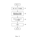
- FIG. FIG. 2 is a flow chart diagram showing the flow of an abnormality determination method according to Embodiment 1;
- FIG. 11 is a block diagram showing the configuration of an abnormality determination system according to Embodiment 2;
- FIG. 2 is a block diagram showing the configuration of an abnormality determination device according to a second embodiment;
- FIG. It is a figure for demonstrating a 1st area. It is a figure for demonstrating a 2nd area.
- FIG. 2 is a flow chart diagram showing the flow of an abnormality determination method according to Embodiment 1;
- FIG. 2 is a flow chart diagram showing the flow of an abnormality determination method according to Embodiment 1;
- FIG. 11 is a block diagram showing the configuration of an abnormality determination system according to Embodiment 2;
- FIG. It is a figure for demonstrating a 2nd area. It is a figure which shows an example of
- the abnormality determination device and abnormality determination method of the present embodiment are suitable, for example, when an optical fiber sensor detects an abnormality in a facility. First, the minimum configuration of the abnormality determination device of this embodiment will be described.
- FIG. 1 is a block diagram showing the minimum configuration of the abnormality determination device of this embodiment.
- the abnormality determination device 1 includes a state information acquisition unit 2, a map information acquisition unit 3, a time information acquisition unit 4, an invalidity information acquisition unit 5, and a determination unit 6, as shown in FIG.
- the state information acquisition unit 2 acquires, for example, the state information inside the first area of the facility, which is the abnormality detection target, detected by the optical fiber sensors arranged to surround the first area.
- the map information acquisition unit 3 acquires map information of the first area.
- the time information acquisition unit 4 acquires current time information.
- the invalidation information acquisition unit 5 provides information indicating a second area that invalidates the detection of anomaly when an anomaly is detected inside the first area, and Acquire information indicating an invalid time zone for invalidating the detection of the abnormality.
- the determination unit 6 determines whether an abnormality has occurred inside the first area based on the state information inside the first area. At this time, when the determination unit 6 detects an abnormality inside the first area, the position where the abnormality is detected is inside the second area, and the time when the abnormality is detected is the invalid time. If it is within the band, it is determined that there is no abnormality in the first area.
- FIG. 2 is a flow chart showing the flow of the abnormality determination method according to this embodiment.
- an inspector sets a first area in which an optical fiber sensor attempts to detect an abnormality (S1).
- the inspector sets a second area that disables the detection of the abnormality when an abnormality is detected inside the first area, and when an abnormality is detected inside the first area
- An invalid time zone for invalidating the detection of the abnormality is set (S2).
- an attempt is made to detect an abnormality inside the first area using an optical fiber sensor (S3). Then, when detecting an abnormality inside the first area, the determination unit 6 determines that the position where the abnormality is detected is inside the second area and the time when the abnormality is detected is the invalid time period. If it is inside, it is determined that no abnormality has occurred inside the first area (S4).
- the abnormality determination device 1 and the abnormality determination method of the present embodiment consider not only the position at which the abnormality is detected but also the time at which the abnormality is detected. are judging. Therefore, compared with the intrusion detection system of Patent Literature 1, erroneous determination of abnormality can be suppressed, and the accuracy of abnormality determination can be improved.
- FIG. 3 is a block diagram showing the configuration of the abnormality determination system of this embodiment.
- FIG. 4 is a block diagram showing the configuration of the abnormality determination device of this embodiment.
- FIG. 5 is a diagram for explaining the first area.
- FIG. 6 is a diagram for explaining the second area.
- An abnormality determination system 11 of the present embodiment includes an optical fiber sensor 12, a mobile object 13, a mobile terminal 14, an abnormality determination device 15, and a storage unit 16, as shown in FIG.
- These optical fiber sensor 12 , moving body 13 , portable terminal 14 , abnormality determination device 15 and storage unit 16 are connected via network 17 .
- the network 17 is, for example, the Internet, and is constructed by telephone network, wireless communication path, Ethernet (registered trademark), and the like.
- the optical fiber sensor 12 includes, for example, an optical fiber, a light source provided at one end of the optical fiber, and a light receiving element provided at the other end of the optical fiber, like a general optical fiber sensor. and optical fibers are arranged to surround the first area.
- Such an optical fiber sensor 12 detects a change in the characteristics of propagating light in the optical fiber due to a change applied to the optical fiber, and thereby detects the state of the inside of the first area as the state inside the first area. It is configured to detect the vibration, temperature or sound of an object, the position of the object, and the like.
- the optical fiber sensor 12 is not limited to the transmission type optical fiber sensor as described above, and a reflection type optical fiber sensor can also be applied.
- the moving body 13 autonomously travels near the position of the object in which an abnormality is detected inside the first area, based on, for example, information indicating a control instruction generated by the control unit 158 of the abnormality determination device 15, which will be described later. .
- the moving body 13 has a position detection section 131 and a periphery detection section 132 .
- the position detection unit 131 includes, for example, a receiver that receives positioning information from a satellite positioning system such as GPS (Global Positioning System), etc. Based on the received positioning information and the map information of the first area , the position of the moving body 13 inside the first area is detected. However, the position detection unit 131 may be configured to detect the position of the moving body 13 inside the first area.
- a satellite positioning system such as GPS (Global Positioning System), etc.
- the peripheral detection unit 132 includes, for example, a camera or LiDar (Light Detection and ranging).
- the periphery detection unit 132 detects, for example, the shape of an object around the moving body 13 and the distance to the object as the surrounding environment of the moving body 13 .
- the moving body 13 may have any configuration as long as it can move within the planar region of the first area, and may be, for example, a drone or a walking robot.
- the mobile terminal 14 is a tablet PC (Personal Computer) or a smartphone possessed by the inspector, and includes a setting section 141 and a display section 142 .
- the setting unit 141 is an input unit that sets the first area, the second area, and the invalid time zone.
- the setting unit 141 may have any configuration as long as it can set the first area, the second area, and the invalid time period, and may be a keyboard of a PC, for example.
- the first area is an anomaly detection target area in which the moving body 13 is moved to try to detect an anomaly.
- the first area AR1 is set as an area including facilities such as a plant, and in FIG. 5 is an area surrounded by a dashed line.
- the planar shape of the first area AR1 is not limited to a rectangular shape, and may be circular, elliptical, or other polygonal shape.
- the second area is an anomaly detection invalid area that invalidates the detection of an anomaly when an anomaly is detected inside the first area AR1.
- the optical fiber sensor 12 detects the vibration or moving sound of the moving object 13, or the vibration or noise of construction work inside the first area AR1, and detects an abnormality inside the first area AR1. It is set not to erroneously determine that a has occurred.
- the second area AR2 is set in an area where vibration and noise occur due to roads on which the moving body 13 moves and construction works inside the first area AR1.
- the area where the road along which the moving body 13 moves is arranged is set as the second area AR2-1 in the inside of the first area AR1, and vibration and noise such as construction work are generated.
- a second area AR2-2 is set as an area to be used.
- the first area AR1 and the second area AR2 are preferably set as map information representing the first area AR1 and the second area AR2 with three-dimensional coordinates.
- the first area AR1 and the second area AR2 can be set as map information represented by three-dimensional coordinates based on the XYZ coordinate system as shown in FIGS. That is, the first area AR1 and the second area AR2 are preferably three-dimensional spaces.
- the invalid time zone is a time zone from the time to start invalidation of detection of anomaly when an anomaly is detected inside the first area AR1 to the time to end it.
- the invalid time zone can be set, for example, to a time zone during which the moving body 13 moves in the second area AR2-1 or a time zone during which construction work is performed in the second area AR2-2.
- the display unit 142 is a display that displays information indicating the surrounding environment of the mobile object 13 .
- the display unit 142 may display information indicating the surrounding environment of the moving body 13, and may be mounted on smart glasses worn by the inspector, for example.
- the abnormality determination device 15 has substantially the same configuration as that of the first embodiment, redundant description will be omitted, but as shown in FIG. It has a section 153 , a route information acquisition section 154 , a map information acquisition section 155 , a time information acquisition section 156 , an invalidity information acquisition section 157 , a control section 158 and a determination section 159 .
- the state information acquisition unit 151 obtains, for example, the vibration, temperature, or sound of an object inside the first area AR1 detected by the optical fiber sensor 12, and information indicating the position of the object inside the first area AR1. and so on.
- the position information acquisition unit 152 acquires information indicating the position of the moving object 13 detected by the position detection unit 131 inside the first area AR1.
- the peripheral information acquisition unit 153 acquires information indicating the peripheral environment of the moving object 13 detected by the peripheral detection unit 132 .
- the information indicating the position of the detected object, the information indicating the position of the moving body 13, and the information indicating the surrounding environment of the moving body 13 are represented by the three-dimensional coordinates of the first area AR1 and the second area AR2. It is preferable that the information is represented by three-dimensional coordinates corresponding to the represented map information.
- the map information acquisition unit 155 acquires map information of the first area AR1.
- the time information acquisition unit 156 acquires current time information from, for example, a clock (not shown).
- the invalidity information acquisition unit 157 acquires map information of the second area AR2 and information indicating an invalid time period during which detection of an abnormality is ignored when an abnormality is detected inside the first area AR1.
- control unit 158 Based on the map information of the first area AR1, the position information of the moving body 13, and the information indicating the position of the detected object, the control unit 158 detects that the moving body 13 has detected an abnormality inside the first area AR1. (i.e., the position of the object that is the source of the detected abnormality that emits vibration, temperature, or sound that matches a preset abnormal vibration, abnormal temperature, or abnormal sound, as described later)
- a control instruction is generated as follows, and the moving body 13 is controlled based on the control instruction.
- control unit 158 is provided in abnormality determination device 15 , but may be provided in moving body 13 .
- the determination unit 159 determines the vibration, temperature, or sound of the object inside the first area AR1 detected by the optical fiber sensor 12 inside the first area AR1, and the vibration of the object inside the first area AR1. Based on the information indicating the position, it is determined whether or not an abnormality has been detected inside the first area AR1.
- the determination unit 159 determines whether or not the vibration, temperature, or sound of the object inside the first area AR1 detected by the optical fiber sensor 12 matches the preset abnormal vibration, temperature, or sound. If they match, it is determined that an abnormality has been detected inside the first area AR1.
- the determination unit 159 determines that the position of the object that is the source of the detected abnormality is inside the second area AR2, and that the abnormality is If the detected time is within the invalid time period, it is determined that no abnormality has occurred in the first area AR1.
- the storage unit 16 stores map information of the first area AR1, map information of the second area AR2, information indicating invalid time zones, and information indicating abnormal vibration, abnormal temperature, or abnormal sound.
- 7 and 8 are flowcharts showing the flow of the abnormality determination method according to this embodiment.
- the inspector sets the first area AR1 via the setting unit 141 of the portable terminal 14 (S11).
- the inspector sets the second area AR2 and the invalid time zone via the setting unit 141 of the portable terminal 14 (S12).
- the state information acquisition unit 151 obtains information such as vibration, temperature or sound of an object inside the first area AR1 and information indicating the position of the object inside the first area AR1 by the optical fiber sensor 12. (S13).
- the determination unit 159 determines whether the information indicating the vibration, temperature, or sound of the object detected by the optical fiber sensor 12 matches the preset abnormal vibration, temperature, or sound (S14 ). If they do not match (NO in S14), the determination unit 159 determines that no abnormality has occurred inside the first area AR1 (S15), and returns to the step of S13.
- the determining unit 159 determines that the object is the first area based on the information indicating the position of the object that is the source of the detected abnormality and the map information of the first area AR1. It is determined whether or not it exists inside the area AR1 (S16).
- the determination unit 159 determines that no abnormality has occurred inside the first area AR1. (S15), returning to the step of S13.
- the determination unit 159 determines that the abnormality has been detected inside the first area AR1. (S17). At this time, the determination unit 159 preferably acquires time information when an abnormality is detected inside the first area AR1.
- the determination unit 159 It is determined that no abnormality has occurred inside the first area AR1 (S15), and the process returns to S13.
- the determination unit 159 determines that an abnormality has occurred inside the first area AR1 (S19).
- the control unit 158 causes the moving body 13 to A control instruction is generated so as to move to the vicinity of the position of , and the moving body 13 is controlled based on the control instruction (S20).
- the peripheral information acquisition unit 153 acquires information indicating the peripheral environment of the mobile object 13 from the peripheral detection unit 132 of the mobile object 13, and outputs the information indicating the peripheral environment of the mobile object 13 to the display unit 142 of the mobile terminal 14. is displayed (S21).
- the abnormality determination system 11, the abnormality determination device 15, and the abnormality determination method of the present embodiment also take into consideration not only the position where the abnormality is detected, but also the time when the abnormality is detected. It determines the occurrence of an internal abnormality. Therefore, compared with the intrusion detection system of Patent Literature 1, erroneous determination of abnormality can be suppressed, and the accuracy of abnormality determination can be improved.
- an erroneous determination based on noise (sound of a train or sound of fireworks) outside the first area AR1. can be suppressed.
- first area AR1 and the second area AR2 are three-dimensional spaces represented by three-dimensional coordinates, for example, it is possible to suppress erroneous determination based on the sound of an airplane flying over the second area AR2. .
- the inspector can quickly confirm the object that is the source of the abnormality.
- the abnormality determination system, the abnormality determination device, and the abnormality determination method of the present embodiment are substantially the same as the abnormality determination system 11, the abnormality determination device 15, and the abnormality determination method of the second embodiment. is different. Therefore, redundant description is omitted, and the same reference numerals are used for the same elements.
- FIG. 9 is a block diagram showing the configuration of the abnormality determination system of this embodiment.
- FIG. 10 is a diagram for explaining the second area.
- the abnormality determination system 21 of the present embodiment includes a first sound generation section 22 and a second sound generation section 23 compared to the configuration of the abnormality determination system 11 of the second embodiment. different in that
- the first sound generation unit 22 is provided in the moving body 13 and generates sound of a preset first frequency.
- the first sound generating unit 22 may be provided, for example, in a vehicle in which a visitor to the facility rides, and generates moving sounds and vibrations when moving within the first area AR1. It is sufficient if it is provided on the object.
- the second sound generating unit 23 is arranged so as to surround an area where vibration and noise are generated due to scheduled construction work, etc., and has a preset second frequency. generate sound.
- the second sound generator 23 may be arranged so as to surround the abnormality detection invalid area.
- the setting unit 141 of the mobile terminal 14 sets the frequency of the first frequency emitted by the first sound generation unit 22 detected by the optical fiber sensor 12 when the mobile object 13 moves within the first area AR1.
- a preset area surrounding the moving body 13 when the sound detection position and the moving sound detection position of the moving body 13 substantially match is set to the second area AR3-1 by the inspector. operated by
- the setting unit 141 of the portable terminal 14 sets the area surrounded by the detection positions of the sounds of the second frequency emitted by the plurality of second sound generating units 23 to the second area AR3- by the optical fiber sensor 12. Operated by the inspector to be set to 2.
- the storage unit 16 stores the Information indicating the first frequency, information indicating the second frequency, information indicating the frequency of the moving sound of the moving object 13, and the like may be stored.
- the determination unit 159 determines whether the movement sound of the moving body 13 matches a preset abnormal sound. However, if the detection position of the sound of the first frequency emitted by the first sound generation unit 22 and the detection position of the moving sound of the moving body 13 substantially match each other, the preset surrounding the moving body 13 is Since the selected area is set to the second area AR3-1, it is determined that no abnormality has occurred inside the first area AR1.
- the determination unit 159 determines whether the noise of the object matches the preset abnormal sound. Also, since the area surrounded by the detection positions of the sound of the second frequency emitted by the plurality of second sound generating units 23 is set as the second area AR3-2, the object is placed in the second area If it is located inside AR3-2, it is determined that no abnormality has occurred inside the first area AR1.
- the area where the movement sound of the moving object 13 is generated, the area where vibration and noise such as construction work are generated, etc. can be easily selected as the second sound generation unit. can be set in the area AR3.
- the abnormality determination device 15 can have the following hardware configuration.
- FIG. 11 is a diagram showing an example of the hardware configuration included in the abnormality determination device 15. As shown in FIG.
- a device 31 shown in FIG. 11 includes an interface 32 as well as a processor 33 and a memory 34 .
- the abnormality determination device 15 described in the above embodiment is implemented by the processor 33 reading and executing a program stored in the memory 34 .
- this program is a program for causing the processor 33 to function as the abnormality determination device 15 .
- a program includes a group of instructions (or software code) that, when read into a computer, cause the computer to perform one or more functions.
- the program may be stored in a non-transitory computer-readable medium or tangible storage medium.
- computer readable media or tangible storage media may include random-access memory (RAM), read-only memory (ROM), flash memory, solid-state drives (SSD) or other memory technology, CDs - ROM, digital versatile disc (DVD), Blu-ray disc or other optical disc storage, magnetic cassette, magnetic tape, magnetic disc storage or other magnetic storage device.
- the program may be transmitted on a transitory computer-readable medium or communication medium.
- transitory computer readable media or communication media include electrical, optical, acoustic, or other forms of propagated signals.
- the moving body 13 in Embodiment 2 described above is configured to travel autonomously, but may be configured to move based on the operation of an inspector. Also, the moving body 13 may be configured to patrol the inside of the first area AR1.
- the setting ranges and setting methods of the second areas AR2 and AR3 in Embodiments 2 and 3 described above are merely examples, and in short, they may cause erroneous determination of abnormality inside the first area AR1. Areas may be set so as to be excluded from the first area AR1.
- Appendix 2 The abnormality determination method according to appendix 1, wherein the first area and the second area are set by three-dimensional coordinates.
- the second area includes a detection position of a sound of a preset first frequency emitted by a first sound generating means provided on a moving body moving inside the first area, and 3.
- the abnormality determination method according to appendix 1 or 2, wherein the detection position of the moving sound and the preset area surrounding the moving object are the same.
- the second area is an area surrounded by detection positions of sounds of a preset second frequency emitted by a plurality of second sound generating means arranged inside the first area,
- the abnormality determination method according to any one of Appendices 1 to 3.
- (Appendix 5) a step of acquiring position information of a moving body moving inside the first area; obtaining map information of the first area; moving the mobile body within the first area based on the location information of the mobile body, the location information where the abnormality is detected, and the map information of the first area, and surrounding environment information of the mobile body; and obtaining 5.
- the abnormality determination method according to any one of appendices 1 to 4, comprising:
- State information acquisition means for acquiring state information inside the first area detected by the optical fiber sensor; map information acquisition means for acquiring map information of the first area; time information acquisition means for acquiring current time information; information indicating a second area for invalidating the detection of the abnormality when an abnormality is detected inside the first area; invalidation information acquisition means for acquiring information indicating an invalidation time zone to be invalidated; determination means for determining whether or not an abnormality has occurred inside the first area based on state information inside the first area; with When the abnormality is detected inside the first area, the determination means determines that the position where the abnormality is detected is inside the second area and the time when the abnormality is detected is the An abnormality determination device that determines that an abnormality does not occur in the first area when it is within the invalid time zone.
- Appendix 8 a positional information obtaining means for obtaining positional information of a moving object moving within the first area; peripheral information acquisition means for acquiring peripheral environment information of the moving object; a control means for controlling the moving body based on the position information of the moving body, the position information where the abnormality is detected, and the map information of the first area;
- the abnormality determination device comprising:
- Appendix 9 An abnormality determination device according to appendix 7 or 8; the optical fiber sensor arranged to surround the first area; setting means for setting the first area, the second area, and the invalid time period; An anomaly determination system.
- a first sound generating means provided on a moving body that moves within the first area and generating a sound of a preset first frequency
- the setting means detects a detection position of the sound of the first frequency emitted by the first sound generating means when the moving body moves within the first area, and sets the moving sound of the moving body.
- the abnormality determination system according to appendix 9, wherein a predetermined area surrounding the moving object when the detection position of and and the detected position of are matched is set as the second area.
- Appendix 12 A plurality of second sound generating means arranged inside the first area and generating sounds of a second frequency set in advance, 12. Any one of appendices 9 to 11, wherein the setting means sets, as the second area, an area surrounded by detection positions of sounds of the second frequency emitted by the plurality of second sound generating means.
- the abnormality determination system according to the item.
- abnormality determination device 1 abnormality determination device 2 status information acquisition unit 3 map information acquisition unit 4 time information acquisition unit 5 invalid information acquisition unit 6 determination unit 11 abnormality determination system 12 optical fiber sensor 13 moving body 131 position detection unit 132 peripheral detection unit 14 mobile phone terminal, 141 setting unit, 142 display unit 15 abnormality determination device, 151 state information acquisition unit, 152 position information acquisition unit, 153 peripheral information acquisition unit, 154 route information acquisition unit, 155 map information acquisition unit, 156 time information acquisition unit, 157 invalid information acquisition unit 158 control unit 159 determination unit 16 storage unit 17 network 21 abnormality determination system 22 first sound generation unit 23 second sound generation unit 31 device 32 interface 33 processor 34 memory AR1 first Area AR2 (AR2-1, AR2-2), AR3 (AR3-1, AR3-2) Second area
Abstract
La présente divulgation met en œuvre un procédé de détermination d'anomalie qui peut contribuer à l'amélioration de la précision de détermination d'anomalies. Un procédé de détermination d'anomalie selon un mode de réalisation de la présente divulgation comprend : une étape consistant à définir une première zone (AR1) dans laquelle est effectuée une tentative de détection d'anomalies à l'aide d'un capteur à fibre optique (12) ; une étape consistant à définir une seconde zone (AR2, AR3) dans laquelle la détection d'anomalie est désactivée lorsqu'une anomalie est détectée dans la première zone (AR1) ; une étape consistant à définir une période de temps de désactivation pendant laquelle une détection d'anomalie est désactivée lorsqu'une anomalie est détectée dans la première zone (AR1) ; et une étape dans laquelle, lorsqu'une anomalie est détectée dans la première zone (AR1), si l'emplacement auquel l'anomalie est détectée se trouve à l'intérieur de la seconde zone (AR2, AR3) et le moment auquel l'anomalie est détectée est dans la période de temps de désactivation, il est déterminé qu'aucune anomalie n'a eu lieu à l'intérieur de la première zone (AR1).
Priority Applications (1)
| Application Number | Priority Date | Filing Date | Title |
|---|---|---|---|
| PCT/JP2021/042232 WO2023089692A1 (fr) | 2021-11-17 | 2021-11-17 | Procédé de détermination d'anomalie, dispositif de détermination d'anomalie, système de détermination d'anomalie et support lisible par ordinateur non transitoire |
Applications Claiming Priority (1)
| Application Number | Priority Date | Filing Date | Title |
|---|---|---|---|
| PCT/JP2021/042232 WO2023089692A1 (fr) | 2021-11-17 | 2021-11-17 | Procédé de détermination d'anomalie, dispositif de détermination d'anomalie, système de détermination d'anomalie et support lisible par ordinateur non transitoire |
Publications (1)
| Publication Number | Publication Date |
|---|---|
| WO2023089692A1 true WO2023089692A1 (fr) | 2023-05-25 |
Family
ID=86396399
Family Applications (1)
| Application Number | Title | Priority Date | Filing Date |
|---|---|---|---|
| PCT/JP2021/042232 WO2023089692A1 (fr) | 2021-11-17 | 2021-11-17 | Procédé de détermination d'anomalie, dispositif de détermination d'anomalie, système de détermination d'anomalie et support lisible par ordinateur non transitoire |
Country Status (1)
| Country | Link |
|---|---|
| WO (1) | WO2023089692A1 (fr) |
Citations (5)
| Publication number | Priority date | Publication date | Assignee | Title |
|---|---|---|---|---|
| JP2011227619A (ja) * | 2010-04-16 | 2011-11-10 | Chugoku Electric Power Co Inc:The | 領域管理システム |
| JP2019071578A (ja) * | 2017-10-11 | 2019-05-09 | パナソニックIpマネジメント株式会社 | 物体検知装置、物体検知システムおよび物体検知方法 |
| WO2020255358A1 (fr) * | 2019-06-20 | 2020-12-24 | 日本電気株式会社 | Système de détection à fibre optique et procédé d'identification de position de source sonore |
| WO2021024388A1 (fr) * | 2019-08-06 | 2021-02-11 | 日本電気株式会社 | Système de détection de fibre optique, dispositif de détection de fibre optique et procédé d'attribution de véhicule aérien sans pilote |
| WO2021171593A1 (fr) * | 2020-02-28 | 2021-09-02 | 日本電気株式会社 | Système de détection, dispositif de détection et procédé de détection |
-
2021
- 2021-11-17 WO PCT/JP2021/042232 patent/WO2023089692A1/fr unknown
Patent Citations (5)
| Publication number | Priority date | Publication date | Assignee | Title |
|---|---|---|---|---|
| JP2011227619A (ja) * | 2010-04-16 | 2011-11-10 | Chugoku Electric Power Co Inc:The | 領域管理システム |
| JP2019071578A (ja) * | 2017-10-11 | 2019-05-09 | パナソニックIpマネジメント株式会社 | 物体検知装置、物体検知システムおよび物体検知方法 |
| WO2020255358A1 (fr) * | 2019-06-20 | 2020-12-24 | 日本電気株式会社 | Système de détection à fibre optique et procédé d'identification de position de source sonore |
| WO2021024388A1 (fr) * | 2019-08-06 | 2021-02-11 | 日本電気株式会社 | Système de détection de fibre optique, dispositif de détection de fibre optique et procédé d'attribution de véhicule aérien sans pilote |
| WO2021171593A1 (fr) * | 2020-02-28 | 2021-09-02 | 日本電気株式会社 | Système de détection, dispositif de détection et procédé de détection |
Similar Documents
| Publication | Publication Date | Title |
|---|---|---|
| JP6506834B2 (ja) | 車両制御 | |
| KR102244175B1 (ko) | 드론 비행 제어 | |
| US20180267540A1 (en) | Movement control system, movement control device, and computer-implemented program for movement control | |
| US8941489B2 (en) | Method and/or apparatus for geofence management | |
| US9691251B2 (en) | Lost child search system, recording medium, and lost child search method | |
| US20120109862A1 (en) | User device and method of recognizing user context | |
| KR102405377B1 (ko) | 관찰 기반 이벤트 추적 | |
| WO2021025660A1 (fr) | Système et procédé de sécurité de personnes basé sur la proximité | |
| CN104937604A (zh) | 基于地点的进程监视 | |
| KR20140077726A (ko) | 유아용 모니터링 로봇 | |
| CN106416397A (zh) | 用于减少的寻呼的ue发起的静止指示符 | |
| JP2017091091A (ja) | 作業情報生成装置 | |
| WO2023089692A1 (fr) | Procédé de détermination d'anomalie, dispositif de détermination d'anomalie, système de détermination d'anomalie et support lisible par ordinateur non transitoire | |
| US20230401941A1 (en) | Monitoring system, monitoring apparatus, monitoring method, and computer readable medium | |
| US10360771B2 (en) | Alert processing | |
| US20210099830A1 (en) | Communication between autonomous vehicles and operations personnel | |
| US9961662B2 (en) | System for tracking assets | |
| JP2019079380A (ja) | データ処理装置およびデータ処理方法 | |
| JPWO2019188429A1 (ja) | 動体管理装置、動体管理システム、動体管理方法、及びコンピュータプログラム | |
| KR101839138B1 (ko) | 구조활동 지원 장치 및 그 동작방법 | |
| JP7343164B2 (ja) | 管理システム及び認証情報提供方法 | |
| JP2019158563A (ja) | 管理装置、管理システム、および位置補正方法 | |
| JP6032424B2 (ja) | 行動検出システム | |
| CN114647305B (zh) | Ar导览中的障碍物提示方法、头戴式显示设备和可读介质 | |
| GB2503207A (en) | Apparatus for determining position and distance to objects |
Legal Events
| Date | Code | Title | Description |
|---|---|---|---|
| 121 | Ep: the epo has been informed by wipo that ep was designated in this application |
Ref document number: 21964708 Country of ref document: EP Kind code of ref document: A1 |