WO2023089692A1 - Abnormality determination method, abnormality determination device, abnormality determination system, and non-transitory computer-readable medium - Google Patents
Abnormality determination method, abnormality determination device, abnormality determination system, and non-transitory computer-readable medium Download PDFInfo
- Publication number
- WO2023089692A1 WO2023089692A1 PCT/JP2021/042232 JP2021042232W WO2023089692A1 WO 2023089692 A1 WO2023089692 A1 WO 2023089692A1 JP 2021042232 W JP2021042232 W JP 2021042232W WO 2023089692 A1 WO2023089692 A1 WO 2023089692A1
- Authority
- WO
- WIPO (PCT)
- Prior art keywords
- area
- abnormality
- detected
- abnormality determination
- information
- Prior art date
Links
Images


Classifications
-
- G—PHYSICS
- G08—SIGNALLING
- G08B—SIGNALLING OR CALLING SYSTEMS; ORDER TELEGRAPHS; ALARM SYSTEMS
- G08B13/00—Burglar, theft or intruder alarms
- G08B13/18—Actuation by interference with heat, light, or radiation of shorter wavelength; Actuation by intruding sources of heat, light, or radiation of shorter wavelength
- G08B13/181—Actuation by interference with heat, light, or radiation of shorter wavelength; Actuation by intruding sources of heat, light, or radiation of shorter wavelength using active radiation detection systems
- G08B13/183—Actuation by interference with heat, light, or radiation of shorter wavelength; Actuation by intruding sources of heat, light, or radiation of shorter wavelength using active radiation detection systems by interruption of a radiation beam or barrier
- G08B13/186—Actuation by interference with heat, light, or radiation of shorter wavelength; Actuation by intruding sources of heat, light, or radiation of shorter wavelength using active radiation detection systems by interruption of a radiation beam or barrier using light guides, e.g. optical fibres
Definitions
- the present disclosure relates to an abnormality determination method, an abnormality determination device, an abnormality determination system, and a non-transitory computer-readable medium.
- Patent Literature 1 determines that there is an intruder in the trajectory when the power variation of the optical fiber sensor exceeds a preset threshold.
- the intrusion detection system of Patent Document 1 determines whether or not the position detected by the optical fiber sensor matches the position of the track maintenance work, and if they match, the optical fiber sensor responds to the track maintenance worker. It is estimated that there is no intruder in the orbit. As a result, the intrusion detection system of Patent Literature 1 suppresses erroneous determination of abnormality by the optical fiber sensor.
- Patent Document 1 suppresses erroneous determination of abnormality by the optical fiber sensor based only on whether or not the position detected by the optical fiber sensor and the position of the track maintenance work match. Therefore, there is room for further suppressing erroneous determination and improving the abnormality determination accuracy.
- One of the objects to be achieved by the embodiments disclosed in this specification is to provide an abnormality determination method, an abnormality determination device, an abnormality determination system, and a non-transitory computer-readable medium that contribute to solving the problem. is. It should be noted that this objective is only one of the objectives that the embodiments disclosed herein seek to achieve. Other objects or problems and novel features will become apparent from the description of the specification or the accompanying drawings.
- An abnormality detection method includes: setting a first area in which the fiber optic sensor attempts to detect anomalies; setting a second area that disables detection of the abnormality when an abnormality is detected inside the first area; setting an invalid time zone for invalidating the detection of the abnormality when an abnormality is detected inside the first area; When an abnormality is detected within the first area, the location where the abnormality is detected is within the second area, and the time when the abnormality is detected is within the invalid time period. a step of determining that no abnormality has occurred inside the first area; Prepare.
- One form of the disclosure is a non-transitory computer-readable medium comprising: A process of setting a first area in which the fiber optic sensor attempts to detect anomalies; a process of setting a second area that disables the detection of the abnormality when an abnormality is detected inside the first area; a process of setting an invalid time zone for invalidating the detection of the anomaly when an anomaly is detected inside the first area; When an abnormality is detected within the first area, the location where the abnormality is detected is within the second area, and the time when the abnormality is detected is within the invalid time period. case, a process of determining that no abnormality has occurred inside the first area; is stored in the computer.
- An abnormality determination device includes: State information acquisition means for acquiring state information inside the first area detected by the optical fiber sensor; map information acquisition means for acquiring map information of the first area; time information acquisition means for acquiring current time information; information indicating a second area for invalidating the detection of the abnormality when an abnormality is detected inside the first area; invalidation information acquisition means for acquiring information indicating an invalidation time zone to be invalidated; determination means for determining whether or not an abnormality has occurred inside the first area based on state information inside the first area; with When the abnormality is detected inside the first area, the determination means determines that the position where the abnormality is detected is inside the second area and the time when the abnormality is detected is the If it is within the invalid time zone, it is determined that no abnormality has occurred in the first area.
- An abnormality determination system includes: the abnormality determination device described above; the optical fiber sensor arranged to surround the first area; setting means for setting the first area, the second area, and the invalid time period; Prepare.
- an abnormality determination method it is possible to realize an abnormality determination method, an abnormality determination device, an abnormality determination system, and a non-temporary computer-readable medium that can contribute to improvement in the accuracy of abnormality determination.
- FIG. 1 is a block diagram showing a minimum configuration of an abnormality determination device according to Embodiment 1;
- FIG. FIG. 2 is a flow chart diagram showing the flow of an abnormality determination method according to Embodiment 1;
- FIG. 11 is a block diagram showing the configuration of an abnormality determination system according to Embodiment 2;
- FIG. 2 is a block diagram showing the configuration of an abnormality determination device according to a second embodiment;
- FIG. It is a figure for demonstrating a 1st area. It is a figure for demonstrating a 2nd area.
- FIG. 2 is a flow chart diagram showing the flow of an abnormality determination method according to Embodiment 1;
- FIG. 2 is a flow chart diagram showing the flow of an abnormality determination method according to Embodiment 1;
- FIG. 11 is a block diagram showing the configuration of an abnormality determination system according to Embodiment 2;
- FIG. It is a figure for demonstrating a 2nd area. It is a figure which shows an example of
- the abnormality determination device and abnormality determination method of the present embodiment are suitable, for example, when an optical fiber sensor detects an abnormality in a facility. First, the minimum configuration of the abnormality determination device of this embodiment will be described.
- FIG. 1 is a block diagram showing the minimum configuration of the abnormality determination device of this embodiment.
- the abnormality determination device 1 includes a state information acquisition unit 2, a map information acquisition unit 3, a time information acquisition unit 4, an invalidity information acquisition unit 5, and a determination unit 6, as shown in FIG.
- the state information acquisition unit 2 acquires, for example, the state information inside the first area of the facility, which is the abnormality detection target, detected by the optical fiber sensors arranged to surround the first area.
- the map information acquisition unit 3 acquires map information of the first area.
- the time information acquisition unit 4 acquires current time information.
- the invalidation information acquisition unit 5 provides information indicating a second area that invalidates the detection of anomaly when an anomaly is detected inside the first area, and Acquire information indicating an invalid time zone for invalidating the detection of the abnormality.
- the determination unit 6 determines whether an abnormality has occurred inside the first area based on the state information inside the first area. At this time, when the determination unit 6 detects an abnormality inside the first area, the position where the abnormality is detected is inside the second area, and the time when the abnormality is detected is the invalid time. If it is within the band, it is determined that there is no abnormality in the first area.
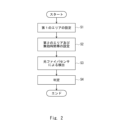
- FIG. 2 is a flow chart showing the flow of the abnormality determination method according to this embodiment.
- an inspector sets a first area in which an optical fiber sensor attempts to detect an abnormality (S1).
- the inspector sets a second area that disables the detection of the abnormality when an abnormality is detected inside the first area, and when an abnormality is detected inside the first area
- An invalid time zone for invalidating the detection of the abnormality is set (S2).
- an attempt is made to detect an abnormality inside the first area using an optical fiber sensor (S3). Then, when detecting an abnormality inside the first area, the determination unit 6 determines that the position where the abnormality is detected is inside the second area and the time when the abnormality is detected is the invalid time period. If it is inside, it is determined that no abnormality has occurred inside the first area (S4).
- the abnormality determination device 1 and the abnormality determination method of the present embodiment consider not only the position at which the abnormality is detected but also the time at which the abnormality is detected. are judging. Therefore, compared with the intrusion detection system of Patent Literature 1, erroneous determination of abnormality can be suppressed, and the accuracy of abnormality determination can be improved.
- FIG. 3 is a block diagram showing the configuration of the abnormality determination system of this embodiment.
- FIG. 4 is a block diagram showing the configuration of the abnormality determination device of this embodiment.
- FIG. 5 is a diagram for explaining the first area.
- FIG. 6 is a diagram for explaining the second area.
- An abnormality determination system 11 of the present embodiment includes an optical fiber sensor 12, a mobile object 13, a mobile terminal 14, an abnormality determination device 15, and a storage unit 16, as shown in FIG.
- These optical fiber sensor 12 , moving body 13 , portable terminal 14 , abnormality determination device 15 and storage unit 16 are connected via network 17 .
- the network 17 is, for example, the Internet, and is constructed by telephone network, wireless communication path, Ethernet (registered trademark), and the like.
- the optical fiber sensor 12 includes, for example, an optical fiber, a light source provided at one end of the optical fiber, and a light receiving element provided at the other end of the optical fiber, like a general optical fiber sensor. and optical fibers are arranged to surround the first area.
- Such an optical fiber sensor 12 detects a change in the characteristics of propagating light in the optical fiber due to a change applied to the optical fiber, and thereby detects the state of the inside of the first area as the state inside the first area. It is configured to detect the vibration, temperature or sound of an object, the position of the object, and the like.
- the optical fiber sensor 12 is not limited to the transmission type optical fiber sensor as described above, and a reflection type optical fiber sensor can also be applied.
- the moving body 13 autonomously travels near the position of the object in which an abnormality is detected inside the first area, based on, for example, information indicating a control instruction generated by the control unit 158 of the abnormality determination device 15, which will be described later. .
- the moving body 13 has a position detection section 131 and a periphery detection section 132 .
- the position detection unit 131 includes, for example, a receiver that receives positioning information from a satellite positioning system such as GPS (Global Positioning System), etc. Based on the received positioning information and the map information of the first area , the position of the moving body 13 inside the first area is detected. However, the position detection unit 131 may be configured to detect the position of the moving body 13 inside the first area.
- a satellite positioning system such as GPS (Global Positioning System), etc.
- the peripheral detection unit 132 includes, for example, a camera or LiDar (Light Detection and ranging).
- the periphery detection unit 132 detects, for example, the shape of an object around the moving body 13 and the distance to the object as the surrounding environment of the moving body 13 .
- the moving body 13 may have any configuration as long as it can move within the planar region of the first area, and may be, for example, a drone or a walking robot.
- the mobile terminal 14 is a tablet PC (Personal Computer) or a smartphone possessed by the inspector, and includes a setting section 141 and a display section 142 .
- the setting unit 141 is an input unit that sets the first area, the second area, and the invalid time zone.
- the setting unit 141 may have any configuration as long as it can set the first area, the second area, and the invalid time period, and may be a keyboard of a PC, for example.
- the first area is an anomaly detection target area in which the moving body 13 is moved to try to detect an anomaly.
- the first area AR1 is set as an area including facilities such as a plant, and in FIG. 5 is an area surrounded by a dashed line.
- the planar shape of the first area AR1 is not limited to a rectangular shape, and may be circular, elliptical, or other polygonal shape.
- the second area is an anomaly detection invalid area that invalidates the detection of an anomaly when an anomaly is detected inside the first area AR1.
- the optical fiber sensor 12 detects the vibration or moving sound of the moving object 13, or the vibration or noise of construction work inside the first area AR1, and detects an abnormality inside the first area AR1. It is set not to erroneously determine that a has occurred.
- the second area AR2 is set in an area where vibration and noise occur due to roads on which the moving body 13 moves and construction works inside the first area AR1.
- the area where the road along which the moving body 13 moves is arranged is set as the second area AR2-1 in the inside of the first area AR1, and vibration and noise such as construction work are generated.
- a second area AR2-2 is set as an area to be used.
- the first area AR1 and the second area AR2 are preferably set as map information representing the first area AR1 and the second area AR2 with three-dimensional coordinates.
- the first area AR1 and the second area AR2 can be set as map information represented by three-dimensional coordinates based on the XYZ coordinate system as shown in FIGS. That is, the first area AR1 and the second area AR2 are preferably three-dimensional spaces.
- the invalid time zone is a time zone from the time to start invalidation of detection of anomaly when an anomaly is detected inside the first area AR1 to the time to end it.
- the invalid time zone can be set, for example, to a time zone during which the moving body 13 moves in the second area AR2-1 or a time zone during which construction work is performed in the second area AR2-2.
- the display unit 142 is a display that displays information indicating the surrounding environment of the mobile object 13 .
- the display unit 142 may display information indicating the surrounding environment of the moving body 13, and may be mounted on smart glasses worn by the inspector, for example.
- the abnormality determination device 15 has substantially the same configuration as that of the first embodiment, redundant description will be omitted, but as shown in FIG. It has a section 153 , a route information acquisition section 154 , a map information acquisition section 155 , a time information acquisition section 156 , an invalidity information acquisition section 157 , a control section 158 and a determination section 159 .
- the state information acquisition unit 151 obtains, for example, the vibration, temperature, or sound of an object inside the first area AR1 detected by the optical fiber sensor 12, and information indicating the position of the object inside the first area AR1. and so on.
- the position information acquisition unit 152 acquires information indicating the position of the moving object 13 detected by the position detection unit 131 inside the first area AR1.
- the peripheral information acquisition unit 153 acquires information indicating the peripheral environment of the moving object 13 detected by the peripheral detection unit 132 .
- the information indicating the position of the detected object, the information indicating the position of the moving body 13, and the information indicating the surrounding environment of the moving body 13 are represented by the three-dimensional coordinates of the first area AR1 and the second area AR2. It is preferable that the information is represented by three-dimensional coordinates corresponding to the represented map information.
- the map information acquisition unit 155 acquires map information of the first area AR1.
- the time information acquisition unit 156 acquires current time information from, for example, a clock (not shown).
- the invalidity information acquisition unit 157 acquires map information of the second area AR2 and information indicating an invalid time period during which detection of an abnormality is ignored when an abnormality is detected inside the first area AR1.
- control unit 158 Based on the map information of the first area AR1, the position information of the moving body 13, and the information indicating the position of the detected object, the control unit 158 detects that the moving body 13 has detected an abnormality inside the first area AR1. (i.e., the position of the object that is the source of the detected abnormality that emits vibration, temperature, or sound that matches a preset abnormal vibration, abnormal temperature, or abnormal sound, as described later)
- a control instruction is generated as follows, and the moving body 13 is controlled based on the control instruction.
- control unit 158 is provided in abnormality determination device 15 , but may be provided in moving body 13 .
- the determination unit 159 determines the vibration, temperature, or sound of the object inside the first area AR1 detected by the optical fiber sensor 12 inside the first area AR1, and the vibration of the object inside the first area AR1. Based on the information indicating the position, it is determined whether or not an abnormality has been detected inside the first area AR1.
- the determination unit 159 determines whether or not the vibration, temperature, or sound of the object inside the first area AR1 detected by the optical fiber sensor 12 matches the preset abnormal vibration, temperature, or sound. If they match, it is determined that an abnormality has been detected inside the first area AR1.
- the determination unit 159 determines that the position of the object that is the source of the detected abnormality is inside the second area AR2, and that the abnormality is If the detected time is within the invalid time period, it is determined that no abnormality has occurred in the first area AR1.
- the storage unit 16 stores map information of the first area AR1, map information of the second area AR2, information indicating invalid time zones, and information indicating abnormal vibration, abnormal temperature, or abnormal sound.
- 7 and 8 are flowcharts showing the flow of the abnormality determination method according to this embodiment.
- the inspector sets the first area AR1 via the setting unit 141 of the portable terminal 14 (S11).
- the inspector sets the second area AR2 and the invalid time zone via the setting unit 141 of the portable terminal 14 (S12).
- the state information acquisition unit 151 obtains information such as vibration, temperature or sound of an object inside the first area AR1 and information indicating the position of the object inside the first area AR1 by the optical fiber sensor 12. (S13).
- the determination unit 159 determines whether the information indicating the vibration, temperature, or sound of the object detected by the optical fiber sensor 12 matches the preset abnormal vibration, temperature, or sound (S14 ). If they do not match (NO in S14), the determination unit 159 determines that no abnormality has occurred inside the first area AR1 (S15), and returns to the step of S13.
- the determining unit 159 determines that the object is the first area based on the information indicating the position of the object that is the source of the detected abnormality and the map information of the first area AR1. It is determined whether or not it exists inside the area AR1 (S16).
- the determination unit 159 determines that no abnormality has occurred inside the first area AR1. (S15), returning to the step of S13.
- the determination unit 159 determines that the abnormality has been detected inside the first area AR1. (S17). At this time, the determination unit 159 preferably acquires time information when an abnormality is detected inside the first area AR1.
- the determination unit 159 It is determined that no abnormality has occurred inside the first area AR1 (S15), and the process returns to S13.
- the determination unit 159 determines that an abnormality has occurred inside the first area AR1 (S19).
- the control unit 158 causes the moving body 13 to A control instruction is generated so as to move to the vicinity of the position of , and the moving body 13 is controlled based on the control instruction (S20).
- the peripheral information acquisition unit 153 acquires information indicating the peripheral environment of the mobile object 13 from the peripheral detection unit 132 of the mobile object 13, and outputs the information indicating the peripheral environment of the mobile object 13 to the display unit 142 of the mobile terminal 14. is displayed (S21).
- the abnormality determination system 11, the abnormality determination device 15, and the abnormality determination method of the present embodiment also take into consideration not only the position where the abnormality is detected, but also the time when the abnormality is detected. It determines the occurrence of an internal abnormality. Therefore, compared with the intrusion detection system of Patent Literature 1, erroneous determination of abnormality can be suppressed, and the accuracy of abnormality determination can be improved.
- an erroneous determination based on noise (sound of a train or sound of fireworks) outside the first area AR1. can be suppressed.
- first area AR1 and the second area AR2 are three-dimensional spaces represented by three-dimensional coordinates, for example, it is possible to suppress erroneous determination based on the sound of an airplane flying over the second area AR2. .
- the inspector can quickly confirm the object that is the source of the abnormality.
- the abnormality determination system, the abnormality determination device, and the abnormality determination method of the present embodiment are substantially the same as the abnormality determination system 11, the abnormality determination device 15, and the abnormality determination method of the second embodiment. is different. Therefore, redundant description is omitted, and the same reference numerals are used for the same elements.
- FIG. 9 is a block diagram showing the configuration of the abnormality determination system of this embodiment.
- FIG. 10 is a diagram for explaining the second area.
- the abnormality determination system 21 of the present embodiment includes a first sound generation section 22 and a second sound generation section 23 compared to the configuration of the abnormality determination system 11 of the second embodiment. different in that
- the first sound generation unit 22 is provided in the moving body 13 and generates sound of a preset first frequency.
- the first sound generating unit 22 may be provided, for example, in a vehicle in which a visitor to the facility rides, and generates moving sounds and vibrations when moving within the first area AR1. It is sufficient if it is provided on the object.
- the second sound generating unit 23 is arranged so as to surround an area where vibration and noise are generated due to scheduled construction work, etc., and has a preset second frequency. generate sound.
- the second sound generator 23 may be arranged so as to surround the abnormality detection invalid area.
- the setting unit 141 of the mobile terminal 14 sets the frequency of the first frequency emitted by the first sound generation unit 22 detected by the optical fiber sensor 12 when the mobile object 13 moves within the first area AR1.
- a preset area surrounding the moving body 13 when the sound detection position and the moving sound detection position of the moving body 13 substantially match is set to the second area AR3-1 by the inspector. operated by
- the setting unit 141 of the portable terminal 14 sets the area surrounded by the detection positions of the sounds of the second frequency emitted by the plurality of second sound generating units 23 to the second area AR3- by the optical fiber sensor 12. Operated by the inspector to be set to 2.
- the storage unit 16 stores the Information indicating the first frequency, information indicating the second frequency, information indicating the frequency of the moving sound of the moving object 13, and the like may be stored.
- the determination unit 159 determines whether the movement sound of the moving body 13 matches a preset abnormal sound. However, if the detection position of the sound of the first frequency emitted by the first sound generation unit 22 and the detection position of the moving sound of the moving body 13 substantially match each other, the preset surrounding the moving body 13 is Since the selected area is set to the second area AR3-1, it is determined that no abnormality has occurred inside the first area AR1.
- the determination unit 159 determines whether the noise of the object matches the preset abnormal sound. Also, since the area surrounded by the detection positions of the sound of the second frequency emitted by the plurality of second sound generating units 23 is set as the second area AR3-2, the object is placed in the second area If it is located inside AR3-2, it is determined that no abnormality has occurred inside the first area AR1.
- the area where the movement sound of the moving object 13 is generated, the area where vibration and noise such as construction work are generated, etc. can be easily selected as the second sound generation unit. can be set in the area AR3.
- the abnormality determination device 15 can have the following hardware configuration.
- FIG. 11 is a diagram showing an example of the hardware configuration included in the abnormality determination device 15. As shown in FIG.
- a device 31 shown in FIG. 11 includes an interface 32 as well as a processor 33 and a memory 34 .
- the abnormality determination device 15 described in the above embodiment is implemented by the processor 33 reading and executing a program stored in the memory 34 .
- this program is a program for causing the processor 33 to function as the abnormality determination device 15 .
- a program includes a group of instructions (or software code) that, when read into a computer, cause the computer to perform one or more functions.
- the program may be stored in a non-transitory computer-readable medium or tangible storage medium.
- computer readable media or tangible storage media may include random-access memory (RAM), read-only memory (ROM), flash memory, solid-state drives (SSD) or other memory technology, CDs - ROM, digital versatile disc (DVD), Blu-ray disc or other optical disc storage, magnetic cassette, magnetic tape, magnetic disc storage or other magnetic storage device.
- the program may be transmitted on a transitory computer-readable medium or communication medium.
- transitory computer readable media or communication media include electrical, optical, acoustic, or other forms of propagated signals.
- the moving body 13 in Embodiment 2 described above is configured to travel autonomously, but may be configured to move based on the operation of an inspector. Also, the moving body 13 may be configured to patrol the inside of the first area AR1.
- the setting ranges and setting methods of the second areas AR2 and AR3 in Embodiments 2 and 3 described above are merely examples, and in short, they may cause erroneous determination of abnormality inside the first area AR1. Areas may be set so as to be excluded from the first area AR1.
- Appendix 2 The abnormality determination method according to appendix 1, wherein the first area and the second area are set by three-dimensional coordinates.
- the second area includes a detection position of a sound of a preset first frequency emitted by a first sound generating means provided on a moving body moving inside the first area, and 3.
- the abnormality determination method according to appendix 1 or 2, wherein the detection position of the moving sound and the preset area surrounding the moving object are the same.
- the second area is an area surrounded by detection positions of sounds of a preset second frequency emitted by a plurality of second sound generating means arranged inside the first area,
- the abnormality determination method according to any one of Appendices 1 to 3.
- (Appendix 5) a step of acquiring position information of a moving body moving inside the first area; obtaining map information of the first area; moving the mobile body within the first area based on the location information of the mobile body, the location information where the abnormality is detected, and the map information of the first area, and surrounding environment information of the mobile body; and obtaining 5.
- the abnormality determination method according to any one of appendices 1 to 4, comprising:
- State information acquisition means for acquiring state information inside the first area detected by the optical fiber sensor; map information acquisition means for acquiring map information of the first area; time information acquisition means for acquiring current time information; information indicating a second area for invalidating the detection of the abnormality when an abnormality is detected inside the first area; invalidation information acquisition means for acquiring information indicating an invalidation time zone to be invalidated; determination means for determining whether or not an abnormality has occurred inside the first area based on state information inside the first area; with When the abnormality is detected inside the first area, the determination means determines that the position where the abnormality is detected is inside the second area and the time when the abnormality is detected is the An abnormality determination device that determines that an abnormality does not occur in the first area when it is within the invalid time zone.
- Appendix 8 a positional information obtaining means for obtaining positional information of a moving object moving within the first area; peripheral information acquisition means for acquiring peripheral environment information of the moving object; a control means for controlling the moving body based on the position information of the moving body, the position information where the abnormality is detected, and the map information of the first area;
- the abnormality determination device comprising:
- Appendix 9 An abnormality determination device according to appendix 7 or 8; the optical fiber sensor arranged to surround the first area; setting means for setting the first area, the second area, and the invalid time period; An anomaly determination system.
- a first sound generating means provided on a moving body that moves within the first area and generating a sound of a preset first frequency
- the setting means detects a detection position of the sound of the first frequency emitted by the first sound generating means when the moving body moves within the first area, and sets the moving sound of the moving body.
- the abnormality determination system according to appendix 9, wherein a predetermined area surrounding the moving object when the detection position of and and the detected position of are matched is set as the second area.
- Appendix 12 A plurality of second sound generating means arranged inside the first area and generating sounds of a second frequency set in advance, 12. Any one of appendices 9 to 11, wherein the setting means sets, as the second area, an area surrounded by detection positions of sounds of the second frequency emitted by the plurality of second sound generating means.
- the abnormality determination system according to the item.
- abnormality determination device 1 abnormality determination device 2 status information acquisition unit 3 map information acquisition unit 4 time information acquisition unit 5 invalid information acquisition unit 6 determination unit 11 abnormality determination system 12 optical fiber sensor 13 moving body 131 position detection unit 132 peripheral detection unit 14 mobile phone terminal, 141 setting unit, 142 display unit 15 abnormality determination device, 151 state information acquisition unit, 152 position information acquisition unit, 153 peripheral information acquisition unit, 154 route information acquisition unit, 155 map information acquisition unit, 156 time information acquisition unit, 157 invalid information acquisition unit 158 control unit 159 determination unit 16 storage unit 17 network 21 abnormality determination system 22 first sound generation unit 23 second sound generation unit 31 device 32 interface 33 processor 34 memory AR1 first Area AR2 (AR2-1, AR2-2), AR3 (AR3-1, AR3-2) Second area
Abstract
The present disclosure implements an abnormality determination method that can contribute to the improvement of the accuracy of determining abnormalities. An abnormality determination method according to an embodiment of the present disclosure comprises: a step for setting a first area (AR1) where an attempt is made to detect abnormalities using an optical fiber sensor (12); a step for setting a second area (AR2, AR3) where abnormality detection is disabled when an abnormality is detected within the first area (AR1); a step for setting a disabling time period during which abnormality detection is disabled when an abnormality is detected within the first area (AR1); and a step wherein when an abnormality is detected within the first area (AR1), if the location at which the abnormality is detected is within the second area (AR2, AR3) and the time at which the abnormality is detected is within the disabling time period, then it is determined that no abnormalities have occurred within the first area (AR1).
Description
本開示は、異常判定方法、異常判定装置、異常判定システム及び非一時的なコンピュータ可読媒体に関する。
The present disclosure relates to an abnormality determination method, an abnormality determination device, an abnormality determination system, and a non-transitory computer-readable medium.
近年、光ファイバセンサを用いて異常を検出する技術が実現されている。例えば、特許文献1の侵入検出システムは、光ファイバセンサのパワー変動が予め設定された閾値を超える場合、軌道内に侵入者が存在すると判定している。
In recent years, technology that detects anomalies using optical fiber sensors has been realized. For example, the intrusion detection system of Patent Literature 1 determines that there is an intruder in the trajectory when the power variation of the optical fiber sensor exceeds a preset threshold.
このとき、特許文献1の侵入検出システムは、光ファイバセンサによる検出位置が保線作業の位置と一致するか否かを判定し、一致する場合、光ファイバセンサが保線作業員に反応しているものと推定し、軌道内への侵入者が存在しないと判定している。これにより、特許文献1の侵入検出システムは、光ファイバセンサによる異常の誤判定を抑制している。
At this time, the intrusion detection system of Patent Document 1 determines whether or not the position detected by the optical fiber sensor matches the position of the track maintenance work, and if they match, the optical fiber sensor responds to the track maintenance worker. It is estimated that there is no intruder in the orbit. As a result, the intrusion detection system of Patent Literature 1 suppresses erroneous determination of abnormality by the optical fiber sensor.
特許文献1の侵入検出システムは、光ファイバセンサによる検出位置と保線作業の位置とが一致するか否かのみに基づいて、光ファイバセンサによる異常の誤判定を抑制している。そのため、誤判定を更に抑制し、異常判定精度の向上の余地が有る。
The intrusion detection system of Patent Document 1 suppresses erroneous determination of abnormality by the optical fiber sensor based only on whether or not the position detected by the optical fiber sensor and the position of the track maintenance work match. Therefore, there is room for further suppressing erroneous determination and improving the abnormality determination accuracy.
本明細書に開示される実施形態が達成しようとする目的の1つは、当該課題の解決に寄与する異常判定方法、異常判定装置、異常判定システム及び非一時的なコンピュータ可読媒体を提供することである。なお、この目的は、本明細書に開示される複数の実施形態が達成しようとする複数の目的の1つに過ぎないことに留意されるべきである。その他の目的又は課題と新規な特徴は、本明細書の記述又は添付図面から明らかにされる。
One of the objects to be achieved by the embodiments disclosed in this specification is to provide an abnormality determination method, an abnormality determination device, an abnormality determination system, and a non-transitory computer-readable medium that contribute to solving the problem. is. It should be noted that this objective is only one of the objectives that the embodiments disclosed herein seek to achieve. Other objects or problems and novel features will become apparent from the description of the specification or the accompanying drawings.
本開示の一形態に係る異常検出方法は、
光ファイバセンサによって異常の検出を試みる第1のエリアを設定する工程と、
前記第1のエリアの内部で異常を検出した際に前記異常の検出を無効にする第2のエリアを設定する工程と、
前記第1のエリアの内部で異常を検出した際に前記異常の検出を無効にする無効時間帯を設定する工程と、
前記第1のエリアの内部で異常を検出した際に、前記異常が検出された位置が前記第2のエリアの内部であって、且つ、前記異常が検出された時刻が前記無効時間帯内の場合、前記第1のエリアの内部で異常が発生していないと判定する工程と、
を備える。 An abnormality detection method according to one embodiment of the present disclosure includes:
setting a first area in which the fiber optic sensor attempts to detect anomalies;
setting a second area that disables detection of the abnormality when an abnormality is detected inside the first area;
setting an invalid time zone for invalidating the detection of the abnormality when an abnormality is detected inside the first area;
When an abnormality is detected within the first area, the location where the abnormality is detected is within the second area, and the time when the abnormality is detected is within the invalid time period. a step of determining that no abnormality has occurred inside the first area;
Prepare.
本開示の一形態の非一時的なコンピュータ可読媒体は、
光ファイバセンサによって異常の検出を試みる第1のエリアを設定する処理と、
前記第1のエリアの内部で異常を検出した際に前記異常の検出を無効にする第2のエリアを設定する処理と、
前記第1のエリアの内部で異常を検出した際に前記異常の検出を無効にする無効時間帯を設定する処理と、
前記第1のエリアの内部で異常を検出した際に、前記異常が検出された位置が前記第2のエリアの内部であって、且つ、前記異常が検出された時刻が前記無効時間帯内の場合、前記第1のエリアの内部で異常が発生していないと判定する処理と、
をコンピュータに実行させる異常判定プログラムが格納されている。 One form of the disclosure is a non-transitory computer-readable medium comprising:
A process of setting a first area in which the fiber optic sensor attempts to detect anomalies;
a process of setting a second area that disables the detection of the abnormality when an abnormality is detected inside the first area;
a process of setting an invalid time zone for invalidating the detection of the anomaly when an anomaly is detected inside the first area;
When an abnormality is detected within the first area, the location where the abnormality is detected is within the second area, and the time when the abnormality is detected is within the invalid time period. case, a process of determining that no abnormality has occurred inside the first area;
is stored in the computer.
本開示の一形態に係る異常判定装置は、
光ファイバセンサによって検出された第1のエリアの内部の状態情報を取得する状態情報取得手段と、
前記第1のエリアの地図情報を取得する地図情報取得手段と、
現在の時刻情報を取得する時刻情報取得手段と、
前記第1のエリアの内部で異常を検出した際に前記異常の検出を無効にする第2のエリアを示す情報、及び前記第1のエリアの内部で異常を検出した際に前記異常の検出を無効にする無効時間帯を示す情報を取得する無効情報取得手段と、
前記第1のエリアの内部の状態情報に基づいて、前記第1のエリアの内部に異常が発生したか否かを判定する判定手段と、
を備え、
前記判定手段は、前記第1のエリアの内部で異常を検出した際に、前記異常が検出された位置が前記第2のエリアの内部であって、且つ、前記異常が検出された時刻が前記無効時間帯内の場合、前記第1のエリアに異常が発生していないと判定する。 An abnormality determination device according to one embodiment of the present disclosure includes:
State information acquisition means for acquiring state information inside the first area detected by the optical fiber sensor;
map information acquisition means for acquiring map information of the first area;
time information acquisition means for acquiring current time information;
information indicating a second area for invalidating the detection of the abnormality when an abnormality is detected inside the first area; invalidation information acquisition means for acquiring information indicating an invalidation time zone to be invalidated;
determination means for determining whether or not an abnormality has occurred inside the first area based on state information inside the first area;
with
When the abnormality is detected inside the first area, the determination means determines that the position where the abnormality is detected is inside the second area and the time when the abnormality is detected is the If it is within the invalid time zone, it is determined that no abnormality has occurred in the first area.
本開示の一形態に係る異常判定システムは、
上述の異常判定装置と、
前記第1のエリアを囲むように配置された前記光ファイバセンサと、
前記第1のエリア、前記第2のエリア及び前記無効時間帯を設定する設定手段と、
を備える。 An abnormality determination system according to one embodiment of the present disclosure includes:
the abnormality determination device described above;
the optical fiber sensor arranged to surround the first area;
setting means for setting the first area, the second area, and the invalid time period;
Prepare.
上述の態様によれば、異常判定精度の向上に寄与可能な、異常判定方法、異常判定装置、異常判定システム及び非一時的なコンピュータ可読媒体を実現できる。
According to the above aspect, it is possible to realize an abnormality determination method, an abnormality determination device, an abnormality determination system, and a non-temporary computer-readable medium that can contribute to improvement in the accuracy of abnormality determination.
以下、本開示を実施するための最良の形態について、添付図面を参照しながら説明する。但し、本開示が以下の実施の形態に限定される訳ではない。また、説明を明確にするため、以下の記載及び図面は、適宜、簡略化されている。
The best mode for carrying out the present disclosure will be described below with reference to the accompanying drawings. However, the present disclosure is not limited to the following embodiments. Also, for clarity of explanation, the following description and drawings are simplified as appropriate.
<実施の形態1>
本実施の形態の異常判定装置及び異常判定方法は、例えば、光ファイバセンサによって施設内の異常を検出する場合に好適である。先ず、本実施の形態の異常判定装置の最小限構成を説明する。 <Embodiment 1>
The abnormality determination device and abnormality determination method of the present embodiment are suitable, for example, when an optical fiber sensor detects an abnormality in a facility. First, the minimum configuration of the abnormality determination device of this embodiment will be described.
本実施の形態の異常判定装置及び異常判定方法は、例えば、光ファイバセンサによって施設内の異常を検出する場合に好適である。先ず、本実施の形態の異常判定装置の最小限構成を説明する。 <
The abnormality determination device and abnormality determination method of the present embodiment are suitable, for example, when an optical fiber sensor detects an abnormality in a facility. First, the minimum configuration of the abnormality determination device of this embodiment will be described.
図1は、本実施の形態の異常判定装置の最小限構成を示すブロック図である。異常判定装置1は、図1に示すように、状態情報取得部2、地図情報取得部3、時刻情報取得部4、無効情報取得部5、及び判定部6を備えている。
FIG. 1 is a block diagram showing the minimum configuration of the abnormality determination device of this embodiment. The abnormality determination device 1 includes a state information acquisition unit 2, a map information acquisition unit 3, a time information acquisition unit 4, an invalidity information acquisition unit 5, and a determination unit 6, as shown in FIG.
状態情報取得部2は、例えば、異常検出対象である施設の第1のエリアを囲むように配置された光ファイバセンサによって検出された当該第1のエリアの内部の状態情報を取得する。地図情報取得部3は、第1のエリアの地図情報を取得する。
The state information acquisition unit 2 acquires, for example, the state information inside the first area of the facility, which is the abnormality detection target, detected by the optical fiber sensors arranged to surround the first area. The map information acquisition unit 3 acquires map information of the first area.
時刻情報取得部4は、現在の時刻情報を取得する。無効情報取得部5は、第1のエリアの内部で異常を検出した際に当該異常の検出を無効にする第2のエリアを示す情報、及び第1のエリアの内部で異常を検出した際に当該異常の検出を無効にする無効時間帯を示す情報を取得する。
The time information acquisition unit 4 acquires current time information. The invalidation information acquisition unit 5 provides information indicating a second area that invalidates the detection of anomaly when an anomaly is detected inside the first area, and Acquire information indicating an invalid time zone for invalidating the detection of the abnormality.
判定部6は、第1のエリアの内部の状態情報に基づいて、第1のエリアの内部に異常が発生したか否かを判定する。このとき、判定部6は、第1のエリアの内部で異常を検出した際に、異常が検出された位置が第2のエリアの内部であって、且つ、異常が検出された時刻が無効時間帯内の場合、第1のエリアに異常が発生していないと判定する。
The determination unit 6 determines whether an abnormality has occurred inside the first area based on the state information inside the first area. At this time, when the determination unit 6 detects an abnormality inside the first area, the position where the abnormality is detected is inside the second area, and the time when the abnormality is detected is the invalid time. If it is within the band, it is determined that there is no abnormality in the first area.
次に、本実施の形態の異常判定方法の流れを説明する。図2は、本実施の形態の異常判定方法の流れを示すフローチャート図である。先ず、検査員は、光ファイバセンサによって異常の検出を試みる第1のエリアを設定する(S1)。
Next, the flow of the abnormality determination method according to this embodiment will be described. FIG. 2 is a flow chart showing the flow of the abnormality determination method according to this embodiment. First, an inspector sets a first area in which an optical fiber sensor attempts to detect an abnormality (S1).
次に、検査員は、第1のエリアの内部で異常を検出した際に当該異常の検出を無効にする第2のエリアを設定すると共に、第1のエリアの内部で異常を検出した際に当該異常の検出を無効にする無効時間帯を設定する(S2)。
Next, the inspector sets a second area that disables the detection of the abnormality when an abnormality is detected inside the first area, and when an abnormality is detected inside the first area An invalid time zone for invalidating the detection of the abnormality is set (S2).
次に、光ファイバセンサによって第1のエリアの内部での異常の検出を試みる(S3)。そして、判定部6は、第1のエリアの内部で異常を検出した際に、異常が検出された位置が第2のエリアの内部であって、且つ、異常が検出された時刻が無効時間帯内の場合、第1のエリアの内部で異常が発生していないと判定する(S4)。
Next, an attempt is made to detect an abnormality inside the first area using an optical fiber sensor (S3). Then, when detecting an abnormality inside the first area, the determination unit 6 determines that the position where the abnormality is detected is inside the second area and the time when the abnormality is detected is the invalid time period. If it is inside, it is determined that no abnormality has occurred inside the first area (S4).
このように本実施の形態の異常判定装置1及び異常判定方法は、異常が検出された位置だけではなく、異常が検出された時刻も考慮して、第1のエリアの内部での異常の発生を判定している。そのため、特許文献1の侵入検出システムに比べて、異常の誤判定を抑制でき、異常判定精度の向上に寄与できる。
As described above, the abnormality determination device 1 and the abnormality determination method of the present embodiment consider not only the position at which the abnormality is detected but also the time at which the abnormality is detected. are judging. Therefore, compared with the intrusion detection system of Patent Literature 1, erroneous determination of abnormality can be suppressed, and the accuracy of abnormality determination can be improved.
<実施の形態2>
本実施の形態では、実施の形態1の異常判定装置1及び異常判定方法に対して、より好ましい異常判定装置を備える異常判定システム及び異常判定方法を説明する。図3は、本実施の形態の異常判定システムの構成を示すブロック図である。図4は、本実施の形態の異常判定装置の構成を示すブロック図である。図5は、第1のエリアを説明するための図である。図6は、第2のエリアを説明するための図である。 <Embodiment 2>
In the present embodiment, an abnormality determination system and an abnormality determination method provided with a more preferable abnormality determination apparatus than theabnormality determination apparatus 1 and the abnormality determination method of the first embodiment will be described. FIG. 3 is a block diagram showing the configuration of the abnormality determination system of this embodiment. FIG. 4 is a block diagram showing the configuration of the abnormality determination device of this embodiment. FIG. 5 is a diagram for explaining the first area. FIG. 6 is a diagram for explaining the second area.
本実施の形態では、実施の形態1の異常判定装置1及び異常判定方法に対して、より好ましい異常判定装置を備える異常判定システム及び異常判定方法を説明する。図3は、本実施の形態の異常判定システムの構成を示すブロック図である。図4は、本実施の形態の異常判定装置の構成を示すブロック図である。図5は、第1のエリアを説明するための図である。図6は、第2のエリアを説明するための図である。 <
In the present embodiment, an abnormality determination system and an abnormality determination method provided with a more preferable abnormality determination apparatus than the
本実施の形態の異常判定システム11は、図3に示すように、光ファイバセンサ12、移動体13、携帯端末14、異常判定装置15及び格納部16を備えている。これらの光ファイバセンサ12と、移動体13と、携帯端末14と、異常判定装置15と、格納部16と、はネットワーク17を介して接続されている。ここで、ネットワーク17は、例えば、インターネットであり、電話回線網、無線通信路、イーサネット(登録商標)などにより構築されている。
An abnormality determination system 11 of the present embodiment includes an optical fiber sensor 12, a mobile object 13, a mobile terminal 14, an abnormality determination device 15, and a storage unit 16, as shown in FIG. These optical fiber sensor 12 , moving body 13 , portable terminal 14 , abnormality determination device 15 and storage unit 16 are connected via network 17 . Here, the network 17 is, for example, the Internet, and is constructed by telephone network, wireless communication path, Ethernet (registered trademark), and the like.
光ファイバセンサ12は、一般的な光ファイバセンサと同様に、例えば、光ファイバ、光ファイバの一方の端部に設けられた光源、及び光ファイバの他方の端部に設けられた受光素子を備えており、光ファイバが第1のエリアを囲むように配置されている。
The optical fiber sensor 12 includes, for example, an optical fiber, a light source provided at one end of the optical fiber, and a light receiving element provided at the other end of the optical fiber, like a general optical fiber sensor. and optical fibers are arranged to surround the first area.
このような光ファイバセンサ12は、光ファイバに加えられた変化による光ファイバ内の伝搬光の特性の変化を検出することで、第1のエリアの内部の状態として、第1のエリアの内部の物体の振動、温度又は音、及び当該物体の位置などを検出する構成とされている。なお、光ファイバセンサ12としては、上述のような透過型の光ファイバセンサに限らず、反射型の光ファイバセンサを適用することもできる。
Such an optical fiber sensor 12 detects a change in the characteristics of propagating light in the optical fiber due to a change applied to the optical fiber, and thereby detects the state of the inside of the first area as the state inside the first area. It is configured to detect the vibration, temperature or sound of an object, the position of the object, and the like. The optical fiber sensor 12 is not limited to the transmission type optical fiber sensor as described above, and a reflection type optical fiber sensor can also be applied.
移動体13は、例えば、後述する異常判定装置15の制御部158で生成される制御指示を示す情報に基づいて、第1のエリアの内部で異常が検出された物体の位置近傍に自律走行する。移動体13は、位置検出部131及び周辺検出部132を備えている。
The moving body 13 autonomously travels near the position of the object in which an abnormality is detected inside the first area, based on, for example, information indicating a control instruction generated by the control unit 158 of the abnormality determination device 15, which will be described later. . The moving body 13 has a position detection section 131 and a periphery detection section 132 .
位置検出部131は、例えば、GPS(Global Positioning System)などの衛星測位システムからの測位情報を受信する受信機などを備えており、受信した測位情報、及び第1のエリアの地図情報に基づいて、移動体13における第1のエリアの内部での位置を検出する。但し、位置検出部131は、移動体13における第1のエリアの内部での位置を検出可能な構成であればよい。
The position detection unit 131 includes, for example, a receiver that receives positioning information from a satellite positioning system such as GPS (Global Positioning System), etc. Based on the received positioning information and the map information of the first area , the position of the moving body 13 inside the first area is detected. However, the position detection unit 131 may be configured to detect the position of the moving body 13 inside the first area.
周辺検出部132は、例えば、カメラ又はLiDar(Light Detection and ranging)などを備えている。周辺検出部132は、例えば、移動体13の周辺環境として、移動体13の周辺の物体の形状及び当該物体までの距離を検出する。但し、移動体13は、第1のエリアの平面領域内を移動可能な構成であればよく、例えば、ドローンや歩行ロボットなどでもよい。
The peripheral detection unit 132 includes, for example, a camera or LiDar (Light Detection and ranging). The periphery detection unit 132 detects, for example, the shape of an object around the moving body 13 and the distance to the object as the surrounding environment of the moving body 13 . However, the moving body 13 may have any configuration as long as it can move within the planar region of the first area, and may be, for example, a drone or a walking robot.
携帯端末14は、検査員が所持するタブレットPC(Personal Computer)やスマートフォンなどであり、設定部141及び表示部142を備えている。設定部141は、第1のエリア、第2のエリア及び無効時間帯を設定する入力部である。但し、設定部141は、第1のエリア、第2のエリア及び無効時間帯を設定可能な構成であればよく、例えば、PCのキーボードなどでもよい。
The mobile terminal 14 is a tablet PC (Personal Computer) or a smartphone possessed by the inspector, and includes a setting section 141 and a display section 142 . The setting unit 141 is an input unit that sets the first area, the second area, and the invalid time zone. However, the setting unit 141 may have any configuration as long as it can set the first area, the second area, and the invalid time period, and may be a keyboard of a PC, for example.
第1のエリアは、移動体13を移動させて異常の検出を試みる異常検出対象領域である。例えば、図5に示すように、第1のエリアAR1は、プラントなどの施設を含む領域に設定されており、図5では、一点鎖線によって囲まれた領域である。但し、第1のエリアAR1の平面形状は、矩形状に限られず、円形、楕円形又は他の多角形であってもよい。
The first area is an anomaly detection target area in which the moving body 13 is moved to try to detect an anomaly. For example, as shown in FIG. 5, the first area AR1 is set as an area including facilities such as a plant, and in FIG. 5 is an area surrounded by a dashed line. However, the planar shape of the first area AR1 is not limited to a rectangular shape, and may be circular, elliptical, or other polygonal shape.
第2のエリアは、第1のエリアAR1の内部で異常を検出した際に当該異常の検出を無効にする異常検出無効領域である。第2のエリアは、移動体13の振動や移動音、又は第1のエリアAR1の内部での工事の振動や騒音などを光ファイバセンサ12が検出して、第1のエリアAR1の内部で異常が発生したと誤判定しないように設定されている。
The second area is an anomaly detection invalid area that invalidates the detection of an anomaly when an anomaly is detected inside the first area AR1. In the second area, the optical fiber sensor 12 detects the vibration or moving sound of the moving object 13, or the vibration or noise of construction work inside the first area AR1, and detects an abnormality inside the first area AR1. It is set not to erroneously determine that a has occurred.
例えば、図6に示すように、第2のエリアAR2は、第1のエリアAR1の内部において移動体13が移動する道路や工事などで振動や騒音が発生するエリアに設定されており、図6では、二点鎖線によって囲まれた領域である。
For example, as shown in FIG. 6, the second area AR2 is set in an area where vibration and noise occur due to roads on which the moving body 13 moves and construction works inside the first area AR1. is the area surrounded by the two-dot chain line.
つまり、図6では、第1のエリアAR1の内部において、移動体13が移動する道路が配置されたエリアが第2のエリアAR2-1に設定されていると共に、工事などの振動や騒音が発生するエリアが第2のエリアAR2-2に設定されている。
In other words, in FIG. 6, the area where the road along which the moving body 13 moves is arranged is set as the second area AR2-1 in the inside of the first area AR1, and vibration and noise such as construction work are generated. A second area AR2-2 is set as an area to be used.
但し、第2のエリアAR2は、移動体13の振動や移動音、又は第1のエリアAR1の内部での工事の振動や騒音などに基づいて、第1のエリアAR1の内部で異常が発生したと誤判定しないように設定されていればよい。
However, in the second area AR2, an abnormality has occurred inside the first area AR1 due to the vibration or moving sound of the moving body 13, or the vibration or noise of construction work inside the first area AR1. It suffices if it is set so as not to make an erroneous determination as .
このとき、第1のエリアAR1及び第2のエリアAR2は、第1のエリアAR1及び第2のエリアAR2を三次元座標で表した地図情報として設定することが好ましい。例えば、第1のエリアAR1及び第2のエリアAR2は、図5及び図6に示すようなXYZ座標系を基準とする三次元座標で表された地図情報として設定することができる。つまり、第1のエリアAR1及び第2のエリアAR2は、三次元空間であることが好ましい。
At this time, the first area AR1 and the second area AR2 are preferably set as map information representing the first area AR1 and the second area AR2 with three-dimensional coordinates. For example, the first area AR1 and the second area AR2 can be set as map information represented by three-dimensional coordinates based on the XYZ coordinate system as shown in FIGS. That is, the first area AR1 and the second area AR2 are preferably three-dimensional spaces.
無効時間帯は、第1のエリアAR1の内部で異常を検出した際に当該異常の検出の無効を開始する時刻から終了する時刻までの時間帯である。無効時間帯は、例えば、移動体13が第2のエリアAR2-1を移動する時間帯や第2のエリアAR2-2で工事などが行われる時間帯に設定することができる。
The invalid time zone is a time zone from the time to start invalidation of detection of anomaly when an anomaly is detected inside the first area AR1 to the time to end it. The invalid time zone can be set, for example, to a time zone during which the moving body 13 moves in the second area AR2-1 or a time zone during which construction work is performed in the second area AR2-2.
表示部142は、移動体13の周辺環境を示す情報を表示するディスプレイである。但し、表示部142は、移動体13の周辺環境を示す情報を表示可能であればよく、例えば、検査員が装着するスマートグラスなどに搭載されていてもよい。
The display unit 142 is a display that displays information indicating the surrounding environment of the mobile object 13 . However, the display unit 142 may display information indicating the surrounding environment of the moving body 13, and may be mounted on smart glasses worn by the inspector, for example.
異常判定装置15は、実施の形態1と略等しい構成とされているため、重複する説明は省略するが、図4に示すように、状態情報取得部151、位置情報取得部152、周辺情報取得部153、経路情報取得部154、地図情報取得部155、時刻情報取得部156、無効情報取得部157、制御部158、及び判定部159を備えている。
Since the abnormality determination device 15 has substantially the same configuration as that of the first embodiment, redundant description will be omitted, but as shown in FIG. It has a section 153 , a route information acquisition section 154 , a map information acquisition section 155 , a time information acquisition section 156 , an invalidity information acquisition section 157 , a control section 158 and a determination section 159 .
状態情報取得部151は、例えば、光ファイバセンサ12によって検出された第1のエリアAR1の内部の物体の振動、温度又は音、及び第1のエリアAR1の内部での当該物体の位置を示す情報などを取得する。位置情報取得部152は、位置検出部131によって検出された移動体13における第1のエリアAR1の内部での位置を示す情報を取得する。
The state information acquisition unit 151 obtains, for example, the vibration, temperature, or sound of an object inside the first area AR1 detected by the optical fiber sensor 12, and information indicating the position of the object inside the first area AR1. and so on. The position information acquisition unit 152 acquires information indicating the position of the moving object 13 detected by the position detection unit 131 inside the first area AR1.
周辺情報取得部153は、周辺検出部132によって検出された移動体13の周辺環境を示す情報を取得する。このとき、検出された物体の位置を示す情報、移動体13の位置を示す情報、及び移動体13の周辺環境を示す情報は、第1のエリアAR1及び第2のエリアAR2の三次元座標で表した地図情報に対応する三次元座標で表された情報であることが好ましい。
The peripheral information acquisition unit 153 acquires information indicating the peripheral environment of the moving object 13 detected by the peripheral detection unit 132 . At this time, the information indicating the position of the detected object, the information indicating the position of the moving body 13, and the information indicating the surrounding environment of the moving body 13 are represented by the three-dimensional coordinates of the first area AR1 and the second area AR2. It is preferable that the information is represented by three-dimensional coordinates corresponding to the represented map information.
地図情報取得部155は、第1のエリアAR1の地図情報を取得する。時刻情報取得部156は、例えば、図示を省略した時計などから現在の時刻情報を取得する。無効情報取得部157は、第2のエリアAR2の地図情報、及び第1のエリアAR1の内部で異常を検出した際に当該異常の検出を無視する無効時間帯を示す情報を取得する。
The map information acquisition unit 155 acquires map information of the first area AR1. The time information acquisition unit 156 acquires current time information from, for example, a clock (not shown). The invalidity information acquisition unit 157 acquires map information of the second area AR2 and information indicating an invalid time period during which detection of an abnormality is ignored when an abnormality is detected inside the first area AR1.
制御部158は、第1のエリアAR1の地図情報、移動体13の位置情報、及び検出された物体の位置を示す情報に基づいて、移動体13が第1のエリアAR1の内部の異常が検出された位置(即ち、後述のように予め設定された異常振動、異常温度又は異常音と一致する振動、温度又は音を発する、検出された異常の発生源である物体の位置)近傍に移動するように制御指示を生成し、当該制御指示に基づいて、移動体13を制御する。なお、本実施の形態では、制御部158が異常判定装置15に備えられているが、移動体13に備えられてもよい。
Based on the map information of the first area AR1, the position information of the moving body 13, and the information indicating the position of the detected object, the control unit 158 detects that the moving body 13 has detected an abnormality inside the first area AR1. (i.e., the position of the object that is the source of the detected abnormality that emits vibration, temperature, or sound that matches a preset abnormal vibration, abnormal temperature, or abnormal sound, as described later) A control instruction is generated as follows, and the moving body 13 is controlled based on the control instruction. In this embodiment, control unit 158 is provided in abnormality determination device 15 , but may be provided in moving body 13 .
判定部159は、第1のエリアAR1の内部で光ファイバセンサ12によって検出された第1のエリアAR1の内部の物体の振動、温度又は音、及び第1のエリアAR1の内部での当該物体の位置を示す情報に基づいて、第1のエリアAR1の内部で異常を検出したか否かを判定する。
The determination unit 159 determines the vibration, temperature, or sound of the object inside the first area AR1 detected by the optical fiber sensor 12 inside the first area AR1, and the vibration of the object inside the first area AR1. Based on the information indicating the position, it is determined whether or not an abnormality has been detected inside the first area AR1.
詳細には、判定部159は、光ファイバセンサ12によって検出された第1のエリアAR1の内部の物体の振動、温度又は音が予め設定された異常振動、異常温度又は異常音と一致するか否かを判定し、一致する場合、第1のエリアAR1の内部で異常を検出したと判定する。
Specifically, the determination unit 159 determines whether or not the vibration, temperature, or sound of the object inside the first area AR1 detected by the optical fiber sensor 12 matches the preset abnormal vibration, temperature, or sound. If they match, it is determined that an abnormality has been detected inside the first area AR1.
そして、判定部159は、第1のエリアAR1の内部で異常を検出した際に、検出された異常の発生源である物体の位置が第2のエリアAR2の内部であって、且つ、異常が検出された時刻が無効時間帯内の場合、第1のエリアAR1で異常が発生していないと判定する。
Then, when detecting an abnormality inside the first area AR1, the determination unit 159 determines that the position of the object that is the source of the detected abnormality is inside the second area AR2, and that the abnormality is If the detected time is within the invalid time period, it is determined that no abnormality has occurred in the first area AR1.
格納部16は、第1のエリアAR1の地図情報、第2のエリアAR2の地図情報、無効時間帯を示す情報、及び異常振動、異常温度若しくは異常音を示す情報を格納する。
The storage unit 16 stores map information of the first area AR1, map information of the second area AR2, information indicating invalid time zones, and information indicating abnormal vibration, abnormal temperature, or abnormal sound.
次に、本実施の形態の異常判定方法の流れを説明する。図7及び図8は、本実施の形態の異常判定方法の流れを示すフローチャート図である。先ず、例えば、検査員は、携帯端末14の設定部141を介して第1のエリアAR1を設定する(S11)。そして、検査員は、携帯端末14の設定部141を介して第2のエリアAR2及び無効時間帯を設定する(S12)。
Next, the flow of the abnormality determination method according to this embodiment will be described. 7 and 8 are flowcharts showing the flow of the abnormality determination method according to this embodiment. First, for example, the inspector sets the first area AR1 via the setting unit 141 of the portable terminal 14 (S11). Then, the inspector sets the second area AR2 and the invalid time zone via the setting unit 141 of the portable terminal 14 (S12).
次に、状態情報取得部151は、光ファイバセンサ12によって第1のエリアAR1の内部での物体の振動、温度又は音、及び第1のエリアAR1の内部での当該物体の位置を示す情報などを取得する(S13)。
Next, the state information acquisition unit 151 obtains information such as vibration, temperature or sound of an object inside the first area AR1 and information indicating the position of the object inside the first area AR1 by the optical fiber sensor 12. (S13).
次に、判定部159は、光ファイバセンサ12によって検出された物体の振動、温度又は音を示す情報が予め設定された異常振動、異常温度又は異常音と一致するか否かを判定する(S14)。一致しない場合(S14のNO)、判定部159は、第1のエリアAR1の内部で異常が発生していないと判定し(S15)、S13の工程に戻る。
Next, the determination unit 159 determines whether the information indicating the vibration, temperature, or sound of the object detected by the optical fiber sensor 12 matches the preset abnormal vibration, temperature, or sound (S14 ). If they do not match (NO in S14), the determination unit 159 determines that no abnormality has occurred inside the first area AR1 (S15), and returns to the step of S13.
一方、一致する場合(S14のYES)、判定部159は、検出された異常の発生源である物体の位置を示す情報及び第1のエリアAR1の地図情報に基づいて、当該物体が第1のエリアAR1の内部に存在するか否かを判定する(S16)。
On the other hand, if they match (YES in S14), the determining unit 159 determines that the object is the first area based on the information indicating the position of the object that is the source of the detected abnormality and the map information of the first area AR1. It is determined whether or not it exists inside the area AR1 (S16).
検出された異常の発生源である物体が第1のエリアAR1の内部に存在しない場合(S16のNO)、判定部159は、第1のエリアAR1の内部で異常が発生していないと判定し(S15)、S13の工程に戻る。
If the object that is the source of the detected abnormality does not exist inside the first area AR1 (NO in S16), the determination unit 159 determines that no abnormality has occurred inside the first area AR1. (S15), returning to the step of S13.
一方、検出された異常の発生源である物体が第1のエリアAR1の内部に存在する場合(S16のYES)、判定部159は、第1のエリアAR1の内部で異常を検出したと判定する(S17)。このとき、判定部159は、第1のエリアAR1の内部で異常を検出した時刻情報を取得するとよい。
On the other hand, if the object that is the source of the detected abnormality exists inside the first area AR1 (YES in S16), the determination unit 159 determines that the abnormality has been detected inside the first area AR1. (S17). At this time, the determination unit 159 preferably acquires time information when an abnormality is detected inside the first area AR1.
次に、判定部159は、検出された異常の発生源である物体の位置を示す情報、第2のエリアAR2の地図情報、無効時間帯を示す情報及び異常を検出した時刻情報に基づいて、検出された異常の発生源である物体の位置が第2のエリアAR2の内部であって、且つ、異常が検出された時刻が無効時間帯内か否かを判定する(S18)。
Next, based on the information indicating the position of the object that is the source of the detected abnormality, the map information of the second area AR2, the information indicating the invalid time zone, and the time information when the abnormality was detected, It is determined whether the position of the object that is the source of the detected abnormality is inside the second area AR2 and whether the time when the abnormality was detected is within the invalid time period (S18).
検出された異常の発生源である物体の位置が第2のエリアAR2の内部であって、且つ、異常が検出された時刻が無効時間帯内の場合(S18のYES)、判定部159は、第1のエリアAR1の内部で異常が発生していないと判定し(S15)、S13の工程に戻る。
If the position of the object that is the source of the detected abnormality is inside the second area AR2 and the time at which the abnormality was detected is within the invalid time zone (YES in S18), the determination unit 159 It is determined that no abnormality has occurred inside the first area AR1 (S15), and the process returns to S13.
一方、検出された異常の発生源である物体の位置が第2のエリアAR2の内部であって、且つ、異常が検出された時刻が無効時間帯内でない場合(S18のNO)、判定部159は、第1のエリアAR1の内部で異常が発生したと判定する(S19)。
On the other hand, if the position of the object that is the source of the detected abnormality is inside the second area AR2 and the time at which the abnormality was detected is not within the invalid time zone (NO in S18), the determination unit 159 determines that an abnormality has occurred inside the first area AR1 (S19).
次に、制御部158は、第1のエリアAR1の地図情報、移動体13の位置情報、及び検出された異常の発生源である物体の位置を示す情報に基づいて、移動体13が当該物体の位置近傍まで移動するように制御指示を生成し、当該制御指示に基づいて、移動体13を制御する(S20)。そして、周辺情報取得部153は、移動体13の周辺検出部132から当該移動体13の周辺環境を示す情報を取得し、当該移動体13の周辺環境を示す情報を携帯端末14の表示部142に表示させる(S21)。
Next, based on the map information of the first area AR1, the position information of the moving body 13, and the information indicating the position of the object that is the source of the detected abnormality, the control unit 158 causes the moving body 13 to A control instruction is generated so as to move to the vicinity of the position of , and the moving body 13 is controlled based on the control instruction (S20). Then, the peripheral information acquisition unit 153 acquires information indicating the peripheral environment of the mobile object 13 from the peripheral detection unit 132 of the mobile object 13, and outputs the information indicating the peripheral environment of the mobile object 13 to the display unit 142 of the mobile terminal 14. is displayed (S21).
このように本実施の形態の異常判定システム11、異常判定装置15及び異常判定方法も、異常が検出された位置だけではなく、異常が検出された時刻も考慮して、第1のエリアAR1の内部での異常の発生を判定している。そのため、特許文献1の侵入検出システムに比べて、異常の誤判定を抑制でき、異常判定精度の向上に寄与できる。
As described above, the abnormality determination system 11, the abnormality determination device 15, and the abnormality determination method of the present embodiment also take into consideration not only the position where the abnormality is detected, but also the time when the abnormality is detected. It determines the occurrence of an internal abnormality. Therefore, compared with the intrusion detection system of Patent Literature 1, erroneous determination of abnormality can be suppressed, and the accuracy of abnormality determination can be improved.
しかも、第1のエリアAR1の内部で異常を検出したか否かを判定しているので、例えば、第1のエリアAR1の外部での騒音(電車の音や花火の音)などに基づく誤判定を抑制できる。
Moreover, since it is determined whether or not an abnormality is detected inside the first area AR1, for example, an erroneous determination based on noise (sound of a train or sound of fireworks) outside the first area AR1. can be suppressed.
また、第1のエリアAR1及び第2のエリアAR2が3次元座標で表された3次元空間の場合、例えば、第2のエリアAR2の上空を飛行する飛行機の音などに基づく誤判定を抑制できる。
In addition, when the first area AR1 and the second area AR2 are three-dimensional spaces represented by three-dimensional coordinates, for example, it is possible to suppress erroneous determination based on the sound of an airplane flying over the second area AR2. .
また、携帯端末14の表示部142に移動体13の周辺環境を示す情報を表示する場合、検査員が異常の発生源である物体を迅速に確認することができる。
Also, when displaying information indicating the surrounding environment of the moving object 13 on the display unit 142 of the mobile terminal 14, the inspector can quickly confirm the object that is the source of the abnormality.
<実施の形態3>
本実施の形態の異常判定システム、異常判定装置及び異常判定方法は、実施の形態2の異常判定システム11、異常判定装置15及び異常判定方法と略等しいが、第2のエリアAR3を設定する手法が異なる。そのため、重複する説明は省略し、等しい要素には等しい符号を用いて説明する。 <Embodiment 3>
The abnormality determination system, the abnormality determination device, and the abnormality determination method of the present embodiment are substantially the same as theabnormality determination system 11, the abnormality determination device 15, and the abnormality determination method of the second embodiment. is different. Therefore, redundant description is omitted, and the same reference numerals are used for the same elements.
本実施の形態の異常判定システム、異常判定装置及び異常判定方法は、実施の形態2の異常判定システム11、異常判定装置15及び異常判定方法と略等しいが、第2のエリアAR3を設定する手法が異なる。そのため、重複する説明は省略し、等しい要素には等しい符号を用いて説明する。 <Embodiment 3>
The abnormality determination system, the abnormality determination device, and the abnormality determination method of the present embodiment are substantially the same as the
図9は、本実施の形態の異常判定システムの構成を示すブロック図である。図10は、第2のエリアを説明するための図である。本実施の形態の異常判定システム21は、図9に示すように、実施の形態2の異常判定システム11の構成に比べて、第1の音発生部22及び第2の音発生部23を備えている点で異なる。
FIG. 9 is a block diagram showing the configuration of the abnormality determination system of this embodiment. FIG. 10 is a diagram for explaining the second area. As shown in FIG. 9, the abnormality determination system 21 of the present embodiment includes a first sound generation section 22 and a second sound generation section 23 compared to the configuration of the abnormality determination system 11 of the second embodiment. different in that
第1の音発生部22は、例えば、図10に示すように、移動体13に設けられており、予め設定された第1の周波数の音を発生する。但し、第1の音発生部22は、例えば、施設への来訪者などが乗車した車両などに設けられてもよく、第1のエリアAR1の内部を移動する際に移動音や振動を発生させる物に設けられていればよい。
For example, as shown in FIG. 10, the first sound generation unit 22 is provided in the moving body 13 and generates sound of a preset first frequency. However, the first sound generating unit 22 may be provided, for example, in a vehicle in which a visitor to the facility rides, and generates moving sounds and vibrations when moving within the first area AR1. It is sufficient if it is provided on the object.
第2の音発生部23は、例えば、図10に示すように、予定されている工事などの振動や騒音が発生するエリアを囲むように配置されており、予め設定された第2の周波数の音を発生する。但し、第2の音発生部23は、異常検出無効領域を囲むように配置されていればよい。
For example, as shown in FIG. 10, the second sound generating unit 23 is arranged so as to surround an area where vibration and noise are generated due to scheduled construction work, etc., and has a preset second frequency. generate sound. However, the second sound generator 23 may be arranged so as to surround the abnormality detection invalid area.
携帯端末14の設定部141は、第1のエリアAR1の内部で移動体13が移動した際に、光ファイバセンサ12によって検出された、第1の音発生部22が発した第1の周波数の音の検出位置と、移動体13の移動音の検出位置と、が略一致した場合の移動体13を囲む予め設定されたエリアが第2のエリアAR3-1に設定されるように、検査員に操作される。
The setting unit 141 of the mobile terminal 14 sets the frequency of the first frequency emitted by the first sound generation unit 22 detected by the optical fiber sensor 12 when the mobile object 13 moves within the first area AR1. A preset area surrounding the moving body 13 when the sound detection position and the moving sound detection position of the moving body 13 substantially match is set to the second area AR3-1 by the inspector. operated by
また、携帯端末14の設定部141は、光ファイバセンサ12によって、複数の第2の音発生部23が発した第2の周波数の音の検出位置で囲まれたエリアが第2のエリアAR3-2に設定されるように、検査員に操作される。
Further, the setting unit 141 of the portable terminal 14 sets the area surrounded by the detection positions of the sounds of the second frequency emitted by the plurality of second sound generating units 23 to the second area AR3- by the optical fiber sensor 12. Operated by the inspector to be set to 2.
このとき、格納部16は、第1のエリアAR1の地図情報、第2のエリアAR3の地図情報、無効時間帯を示す情報、及び異常振動、異常温度若しくは異常音を示す情報の他に、第1の周波数を示す情報、第2の周波数を示す情報及び移動体13の移動音の周波数を示す情報などを格納しているとよい。
At this time, in addition to the map information of the first area AR1, the map information of the second area AR3, the information indicating the invalid time period, and the information indicating abnormal vibration, abnormal temperature, or abnormal sound, the storage unit 16 stores the Information indicating the first frequency, information indicating the second frequency, information indicating the frequency of the moving sound of the moving object 13, and the like may be stored.
このような異常判定システム21を用いて第1のエリアAR1の内部の異常の発生を判定する場合、実施の形態2の異常判定方法と同様の流れで実施することができる。このとき、判定部159は、異常が検出された物体の位置が第2のエリアAR3の内部か否かを判定する際に、移動体13の移動音が予め設定された異常音に一致する場合であっても、第1の音発生部22が発した第1の周波数の音の検出位置と、移動体13の移動音の検出位置と、が略一致した場合の移動体13を囲む予め設定されたエリアが第2のエリアAR3-1に設定されているので、第1のエリアAR1の内部で異常が発生していないと判定する。
When determining the occurrence of an abnormality inside the first area AR1 using such an abnormality determination system 21, it can be implemented in the same flow as the abnormality determination method of the second embodiment. At this time, when determining whether or not the position of the object in which the abnormality is detected is inside the second area AR3, the determination unit 159 determines whether the movement sound of the moving body 13 matches a preset abnormal sound. However, if the detection position of the sound of the first frequency emitted by the first sound generation unit 22 and the detection position of the moving sound of the moving body 13 substantially match each other, the preset surrounding the moving body 13 is Since the selected area is set to the second area AR3-1, it is determined that no abnormality has occurred inside the first area AR1.
また、判定部159は、異常が検出された物体の位置が第2のエリアAR3の内部か否かを判定する際に、当該物体の騒音が予め設定された異常音に一致する場合であっても、複数の第2の音発生部23が発した第2の周波数の音の検出位置で囲まれたエリアが第2のエリアAR3-2に設定されているので、当該物体が第2のエリアAR3-2の内部に配置されている場合、第1のエリアAR1の内部で異常が発生していないと判定する。
Further, when determining whether or not the position of the object in which the abnormality is detected is inside the second area AR3, the determination unit 159 determines whether the noise of the object matches the preset abnormal sound. Also, since the area surrounded by the detection positions of the sound of the second frequency emitted by the plurality of second sound generating units 23 is set as the second area AR3-2, the object is placed in the second area If it is located inside AR3-2, it is determined that no abnormality has occurred inside the first area AR1.
このように第1の音発生部22及び第2の音発生部23を用いることで、移動体13の移動音が発生するエリアや工事などの振動や騒音が発生するエリアなどを簡単に第2のエリアAR3に設定することができる。
By using the first sound generation unit 22 and the second sound generation unit 23 in this way, the area where the movement sound of the moving object 13 is generated, the area where vibration and noise such as construction work are generated, etc. can be easily selected as the second sound generation unit. can be set in the area AR3.
<他の実施の形態>
なお、上述の実施の形態1乃至3では、本開示をハードウェアの構成として説明したが、本開示はこれに限定されるものではない。本開示は、各構成要素の処理を、CPU(Central Processing Unit)にコンピュータプログラムを実行させることにより実現することも可能である。 <Other embodiments>
Although the present disclosure has been described as a hardware configuration in the first to third embodiments described above, the present disclosure is not limited to this. The present disclosure can also realize the processing of each component by causing a CPU (Central Processing Unit) to execute a computer program.
例えば、上述の実施の形態に係る異常判定装置15は、次のようなハードウェア構成を備えることができる。図11は、異常判定装置15に含まれるハードウェア構成の一例を示す図である。
For example, the abnormality determination device 15 according to the above embodiment can have the following hardware configuration. FIG. 11 is a diagram showing an example of the hardware configuration included in the abnormality determination device 15. As shown in FIG.
図11に示す装置31は、インタフェース32とともに、プロセッサ33及びメモリ34を備えている。上述の実施の形態で説明した異常判定装置15は、プロセッサ33がメモリ34に記憶されたプログラムを読み込んで実行することにより実現される。つまり、このプログラムは、プロセッサ33を異常判定装置15として機能させるためのプログラムである。
A device 31 shown in FIG. 11 includes an interface 32 as well as a processor 33 and a memory 34 . The abnormality determination device 15 described in the above embodiment is implemented by the processor 33 reading and executing a program stored in the memory 34 . In other words, this program is a program for causing the processor 33 to function as the abnormality determination device 15 .
ここで、プログラムは、コンピュータに読み込まれた場合に、1又はそれ以上の機能をコンピュータに行わせるための命令群(又はソフトウェアコード)を含む。プログラムは、非一時的なコンピュータ可読媒体又は実体のある記憶媒体に格納されてもよい。限定ではなく例として、コンピュータ可読媒体又は実体のある記憶媒体は、random-access memory(RAM)、read-only memory(ROM)、フラッシュメモリ、solid-state drive(SSD)又はその他のメモリ技術、CD-ROM、digital versatile disc(DVD)、Blu-ray(登録商標)ディスク又はその他の光ディスクストレージ、磁気カセット、磁気テープ、磁気ディスクストレージ又はその他の磁気ストレージデバイスを含む。プログラムは、一時的なコンピュータ可読媒体又は通信媒体上で送信されてもよい。限定ではなく例として、一時的なコンピュータ可読媒体又は通信媒体は、電気的、光学的、音響的、またはその他の形式の伝搬信号を含む。
Here, a program includes a group of instructions (or software code) that, when read into a computer, cause the computer to perform one or more functions. The program may be stored in a non-transitory computer-readable medium or tangible storage medium. By way of example, and not limitation, computer readable media or tangible storage media may include random-access memory (RAM), read-only memory (ROM), flash memory, solid-state drives (SSD) or other memory technology, CDs - ROM, digital versatile disc (DVD), Blu-ray disc or other optical disc storage, magnetic cassette, magnetic tape, magnetic disc storage or other magnetic storage device. The program may be transmitted on a transitory computer-readable medium or communication medium. By way of example, and not limitation, transitory computer readable media or communication media include electrical, optical, acoustic, or other forms of propagated signals.
なお、本開示は上述の実施の形態に限られたものではなく、趣旨を逸脱しない範囲で適宜変更することが可能である。また、本開示は、それぞれの実施の形態を適宜組み合わせて実施されてもよい。
It should be noted that the present disclosure is not limited to the above-described embodiments, and can be modified as appropriate without departing from the scope. In addition, the present disclosure may be implemented by appropriately combining each embodiment.
例えば、上述の実施の形態2などの移動体13は、自律走行する構成であるが、検査員の操作に基づいて移動する構成であってもよい。また、移動体13は、第1のエリアAR1の内部を巡回する構成であってもよい。
For example, the moving body 13 in Embodiment 2 described above is configured to travel autonomously, but may be configured to move based on the operation of an inspector. Also, the moving body 13 may be configured to patrol the inside of the first area AR1.
例えば、上述の実施の形態2、3での第2のエリアAR2、AR3の設定範囲や設定手法は、一例であり、要するに、第1のエリアAR1の内部での異常の誤判定の起因になるエリアを当該第1のエリアAR1から除外できるように設定すればよい。
For example, the setting ranges and setting methods of the second areas AR2 and AR3 in Embodiments 2 and 3 described above are merely examples, and in short, they may cause erroneous determination of abnormality inside the first area AR1. Areas may be set so as to be excluded from the first area AR1.
上述した実施の形態の一部又は全部は、以下の付記のようにも記載されうるが、以下には限られない。
(付記1)
光ファイバセンサによって異常の検出を試みる第1のエリアを設定する工程と、
前記第1のエリアの内部で異常を検出した際に前記異常の検出を無効にする第2のエリアを設定する工程と、
前記第1のエリアの内部で異常を検出した際に前記異常の検出を無効にする無効時間帯を設定する工程と、
前記第1のエリアの内部で異常を検出した際に、前記異常が検出された位置が前記第2のエリアの内部であって、且つ、前記異常が検出された時刻が前記無効時間帯内の場合、前記第1のエリアの内部で異常が発生していないと判定する工程と、
を備える、異常判定方法。 Some or all of the above-described embodiments can be described in the following additional remarks, but are not limited to the following.
(Appendix 1)
setting a first area in which the fiber optic sensor attempts to detect anomalies;
setting a second area that disables detection of the abnormality when an abnormality is detected inside the first area;
setting an invalid time zone for invalidating the detection of the abnormality when an abnormality is detected inside the first area;
When an abnormality is detected within the first area, the location where the abnormality is detected is within the second area, and the time when the abnormality is detected is within the invalid time period. a step of determining that no abnormality has occurred inside the first area;
Abnormality determination method.
(付記2)
前記第1のエリア及び前記第2のエリアは、3次元座標によって設定する、付記1に記載の異常判定方法。 (Appendix 2)
The abnormality determination method according toappendix 1, wherein the first area and the second area are set by three-dimensional coordinates.
前記第1のエリア及び前記第2のエリアは、3次元座標によって設定する、付記1に記載の異常判定方法。 (Appendix 2)
The abnormality determination method according to
(付記3)
前記第2のエリアは、前記第1のエリアの内部で移動する移動体に設けられた第1の音発生手段が発した予め設定された第1の周波数の音の検出位置と、前記移動体の移動音の検出位置と、が一致した場合の前記移動体を囲む予め設定されたエリアである、付記1又は2に記載の異常判定方法。 (Appendix 3)
The second area includes a detection position of a sound of a preset first frequency emitted by a first sound generating means provided on a moving body moving inside the first area, and 3. The abnormality determination method according to appendix 1 or 2, wherein the detection position of the moving sound and the preset area surrounding the moving object are the same.
前記第2のエリアは、前記第1のエリアの内部で移動する移動体に設けられた第1の音発生手段が発した予め設定された第1の周波数の音の検出位置と、前記移動体の移動音の検出位置と、が一致した場合の前記移動体を囲む予め設定されたエリアである、付記1又は2に記載の異常判定方法。 (Appendix 3)
The second area includes a detection position of a sound of a preset first frequency emitted by a first sound generating means provided on a moving body moving inside the first area, and 3. The abnormality determination method according to
(付記4)
前記第2のエリアは、前記第1のエリアの内部に配置された複数の第2の音発生手段が発した予め設定された第2の周波数の音の検出位置で囲まれたエリアである、付記1乃至3のいずれか1項に記載の異常判定方法。 (Appendix 4)
The second area is an area surrounded by detection positions of sounds of a preset second frequency emitted by a plurality of second sound generating means arranged inside the first area, The abnormality determination method according to any one ofAppendices 1 to 3.
前記第2のエリアは、前記第1のエリアの内部に配置された複数の第2の音発生手段が発した予め設定された第2の周波数の音の検出位置で囲まれたエリアである、付記1乃至3のいずれか1項に記載の異常判定方法。 (Appendix 4)
The second area is an area surrounded by detection positions of sounds of a preset second frequency emitted by a plurality of second sound generating means arranged inside the first area, The abnormality determination method according to any one of
(付記5)
前記第1のエリアの内部を移動する移動体の位置情報を取得する工程と、
前記第1のエリアの地図情報を取得する工程と、
前記移動体の位置情報、前記異常が検出された位置情報及び前記第1のエリアの地図情報に基づいて、前記移動体を前記第1のエリアの内部で移動させ、前記移動体の周辺環境情報を取得する工程と、
を備える、付記1乃至4のいずれか1項に記載の異常判定方法。 (Appendix 5)
a step of acquiring position information of a moving body moving inside the first area;
obtaining map information of the first area;
moving the mobile body within the first area based on the location information of the mobile body, the location information where the abnormality is detected, and the map information of the first area, and surrounding environment information of the mobile body; and obtaining
5. The abnormality determination method according to any one ofappendices 1 to 4, comprising:
前記第1のエリアの内部を移動する移動体の位置情報を取得する工程と、
前記第1のエリアの地図情報を取得する工程と、
前記移動体の位置情報、前記異常が検出された位置情報及び前記第1のエリアの地図情報に基づいて、前記移動体を前記第1のエリアの内部で移動させ、前記移動体の周辺環境情報を取得する工程と、
を備える、付記1乃至4のいずれか1項に記載の異常判定方法。 (Appendix 5)
a step of acquiring position information of a moving body moving inside the first area;
obtaining map information of the first area;
moving the mobile body within the first area based on the location information of the mobile body, the location information where the abnormality is detected, and the map information of the first area, and surrounding environment information of the mobile body; and obtaining
5. The abnormality determination method according to any one of
(付記6)
光ファイバセンサによって異常の検出を試みる第1のエリアを設定する処理と、
前記第1のエリアの内部で異常を検出した際に前記異常の検出を無効にする第2のエリアを設定する処理と、
前記第1のエリアの内部で異常を検出した際に前記異常の検出を無効にする無効時間帯を設定する処理と、
前記第1のエリアの内部で異常を検出した際に、前記異常が検出された位置が前記第2のエリアの内部であって、且つ、前記異常が検出された時刻が前記無効時間帯内の場合、前記第1のエリアの内部で異常が発生していないと判定する処理と、
をコンピュータに実行させる異常判定プログラムが格納された非一時的なコンピュータ可読媒体。 (Appendix 6)
A process of setting a first area in which the fiber optic sensor attempts to detect anomalies;
a process of setting a second area that disables the detection of the abnormality when an abnormality is detected inside the first area;
a process of setting an invalid time zone for invalidating the detection of the anomaly when an anomaly is detected inside the first area;
When an abnormality is detected within the first area, the location where the abnormality is detected is within the second area, and the time when the abnormality is detected is within the invalid time period. case, a process of determining that no abnormality has occurred inside the first area;
A non-transitory computer-readable medium storing an abnormality determination program that causes a computer to execute
(付記7)
光ファイバセンサによって検出された第1のエリアの内部の状態情報を取得する状態情報取得手段と、
前記第1のエリアの地図情報を取得する地図情報取得手段と、
現在の時刻情報を取得する時刻情報取得手段と、
前記第1のエリアの内部で異常を検出した際に前記異常の検出を無効にする第2のエリアを示す情報、及び前記第1のエリアの内部で異常を検出した際に前記異常の検出を無効にする無効時間帯を示す情報を取得する無効情報取得手段と、
前記第1のエリアの内部の状態情報に基づいて、前記第1のエリアの内部に異常が発生したか否かを判定する判定手段と、
を備え、
前記判定手段は、前記第1のエリアの内部で異常を検出した際に、前記異常が検出された位置が前記第2のエリアの内部であって、且つ、前記異常が検出された時刻が前記無効時間帯内の場合、前記第1のエリアに異常が発生していないと判定する、異常判定装置。 (Appendix 7)
State information acquisition means for acquiring state information inside the first area detected by the optical fiber sensor;
map information acquisition means for acquiring map information of the first area;
time information acquisition means for acquiring current time information;
information indicating a second area for invalidating the detection of the abnormality when an abnormality is detected inside the first area; invalidation information acquisition means for acquiring information indicating an invalidation time zone to be invalidated;
determination means for determining whether or not an abnormality has occurred inside the first area based on state information inside the first area;
with
When the abnormality is detected inside the first area, the determination means determines that the position where the abnormality is detected is inside the second area and the time when the abnormality is detected is the An abnormality determination device that determines that an abnormality does not occur in the first area when it is within the invalid time zone.
(付記8)
前記第1のエリアの内部を移動する移動体の位置情報を取得する位置情報取得手段と、
前記移動体の周辺環境情報を取得する周辺情報取得手段と、
前記移動体の位置情報、前記異常が検出された位置情報び前記第1のエリアの地図情報に基づいて、前記移動体を制御する制御手段と、
を備える、付記7に記載の異常判定装置。 (Appendix 8)
a positional information obtaining means for obtaining positional information of a moving object moving within the first area;
peripheral information acquisition means for acquiring peripheral environment information of the moving object;
a control means for controlling the moving body based on the position information of the moving body, the position information where the abnormality is detected, and the map information of the first area;
The abnormality determination device according to appendix 7, comprising:
(付記9)
付記7又は8に記載の異常判定装置と、
前記第1のエリアを囲むように配置された前記光ファイバセンサと、
前記第1のエリア、前記第2のエリア及び前記無効時間帯を設定する設定手段と、
を備える、異常判定システム。 (Appendix 9)
An abnormality determination device according to appendix 7 or 8;
the optical fiber sensor arranged to surround the first area;
setting means for setting the first area, the second area, and the invalid time period;
An anomaly determination system.
(付記10)
前記第1のエリアの内部を移動する移動体に設けられ、予め設定された第1の周波数の音を発生する第1の音発生手段を備え、
前記設定手段は、前記第1のエリアの内部で前記移動体が移動した際に、前記第1の音発生手段が発した前記第1の周波数の音の検出位置と、前記移動体の移動音の検出位置と、が一致した場合の前記移動体を囲む予め設定されたエリアを前記第2のエリアに設定する、付記9に記載の異常判定システム。 (Appendix 10)
A first sound generating means provided on a moving body that moves within the first area and generating a sound of a preset first frequency,
The setting means detects a detection position of the sound of the first frequency emitted by the first sound generating means when the moving body moves within the first area, and sets the moving sound of the moving body. 10. The abnormality determination system according to appendix 9, wherein a predetermined area surrounding the moving object when the detection position of and and the detected position of are matched is set as the second area.
(付記11)
前記移動体に設けられ、前記移動体の周辺環境を検出する周辺検出手段と、
前記移動体の周辺環境を示す情報を表示する表示手段と、
を備える、付記10に記載の異常判定システム。 (Appendix 11)
Periphery detection means provided in the moving body for detecting a surrounding environment of the moving body;
display means for displaying information indicating the surrounding environment of the mobile object;
The abnormality determination system according to appendix 10, comprising:
(付記12)
前記第1のエリアの内部に配置され、予め設定された第2の周波数の音を発生する複数の第2の音発生手段を備え、
前記設定手段は、前記複数の第2の音発生手段が発した前記第2の周波数の音の検出位置で囲まれたエリアを前記第2のエリアに設定する、付記9乃至11のいずれか1項に記載の異常判定システム。 (Appendix 12)
A plurality of second sound generating means arranged inside the first area and generating sounds of a second frequency set in advance,
12. Any one of appendices 9 to 11, wherein the setting means sets, as the second area, an area surrounded by detection positions of sounds of the second frequency emitted by the plurality of second sound generating means. The abnormality determination system according to the item.
1 異常判定装置
2 状態情報取得部
3 地図情報取得部
4 時刻情報取得部
5 無効情報取得部
6 判定部
11 異常判定システム
12 光ファイバセンサ
13 移動体、131 位置検出部、132 周辺検出部
14 携帯端末、141 設定部、142 表示部
15 異常判定装置、151 状態情報取得部、152 位置情報取得部、153 周辺情報取得部、154 経路情報取得部、155 地図情報取得部、156 時刻情報取得部、157 無効情報取得部、158 制御部、159 判定部
16 格納部
17 ネットワーク
21 異常判定システム
22 第1の音発生部
23 第2の音発生部
31 装置、32 インタフェース、33 プロセッサ、34 メモリ
AR1 第1のエリア
AR2(AR2-1、AR2-2)、AR3(AR3-1、AR3-2) 第2のエリア 1abnormality determination device 2 status information acquisition unit 3 map information acquisition unit 4 time information acquisition unit 5 invalid information acquisition unit 6 determination unit 11 abnormality determination system 12 optical fiber sensor 13 moving body 131 position detection unit 132 peripheral detection unit 14 mobile phone terminal, 141 setting unit, 142 display unit 15 abnormality determination device, 151 state information acquisition unit, 152 position information acquisition unit, 153 peripheral information acquisition unit, 154 route information acquisition unit, 155 map information acquisition unit, 156 time information acquisition unit, 157 invalid information acquisition unit 158 control unit 159 determination unit 16 storage unit 17 network 21 abnormality determination system 22 first sound generation unit 23 second sound generation unit 31 device 32 interface 33 processor 34 memory AR1 first Area AR2 (AR2-1, AR2-2), AR3 (AR3-1, AR3-2) Second area
2 状態情報取得部
3 地図情報取得部
4 時刻情報取得部
5 無効情報取得部
6 判定部
11 異常判定システム
12 光ファイバセンサ
13 移動体、131 位置検出部、132 周辺検出部
14 携帯端末、141 設定部、142 表示部
15 異常判定装置、151 状態情報取得部、152 位置情報取得部、153 周辺情報取得部、154 経路情報取得部、155 地図情報取得部、156 時刻情報取得部、157 無効情報取得部、158 制御部、159 判定部
16 格納部
17 ネットワーク
21 異常判定システム
22 第1の音発生部
23 第2の音発生部
31 装置、32 インタフェース、33 プロセッサ、34 メモリ
AR1 第1のエリア
AR2(AR2-1、AR2-2)、AR3(AR3-1、AR3-2) 第2のエリア 1
Claims (12)
- 光ファイバセンサによって異常の検出を試みる第1のエリアを設定する工程と、
前記第1のエリアの内部で異常を検出した際に前記異常の検出を無効にする第2のエリアを設定する工程と、
前記第1のエリアの内部で異常を検出した際に前記異常の検出を無効にする無効時間帯を設定する工程と、
前記第1のエリアの内部で異常を検出した際に、前記異常が検出された位置が前記第2のエリアの内部であって、且つ、前記異常が検出された時刻が前記無効時間帯内の場合、前記第1のエリアの内部で異常が発生していないと判定する工程と、
を備える、異常判定方法。 setting a first area in which the fiber optic sensor attempts to detect anomalies;
setting a second area that disables detection of the abnormality when an abnormality is detected inside the first area;
setting an invalid time zone for invalidating the detection of the abnormality when an abnormality is detected inside the first area;
When an abnormality is detected within the first area, the location where the abnormality is detected is within the second area, and the time when the abnormality is detected is within the invalid time period. a step of determining that no abnormality has occurred inside the first area;
Abnormality determination method. - 前記第1のエリア及び前記第2のエリアは、3次元座標によって設定する、請求項1に記載の異常判定方法。 The abnormality determination method according to claim 1, wherein the first area and the second area are set by three-dimensional coordinates.
- 前記第2のエリアは、前記第1のエリアの内部で移動する移動体に設けられた第1の音発生手段が発した予め設定された第1の周波数の音の検出位置と、前記移動体の移動音の検出位置と、が一致した場合の前記移動体を囲む予め設定されたエリアである、請求項1又は2に記載の異常判定方法。 The second area includes a detection position of a sound of a preset first frequency emitted by a first sound generating means provided on a moving object moving inside the first area, and 3. The abnormality determination method according to claim 1 or 2, wherein the detection position of the moving sound and the preset area surrounding the moving object when the position coincides with the detection position of the moving sound.
- 前記第2のエリアは、前記第1のエリアの内部に配置された複数の第2の音発生手段が発した予め設定された第2の周波数の音の検出位置で囲まれたエリアである、請求項1乃至3のいずれか1項に記載の異常判定方法。 The second area is an area surrounded by detection positions of sounds of a preset second frequency emitted by a plurality of second sound generating means arranged inside the first area, The abnormality determination method according to any one of claims 1 to 3.
- 前記第1のエリアの内部を移動する移動体の位置情報を取得する工程と、
前記第1のエリアの地図情報を取得する工程と、
前記移動体の位置情報、前記異常が検出された位置情報及び前記第1のエリアの地図情報に基づいて、前記移動体を前記第1のエリアの内部で移動させ、前記移動体の周辺環境情報を取得する工程と、
を備える、請求項1乃至4のいずれか1項に記載の異常判定方法。 a step of acquiring position information of a moving body moving inside the first area;
obtaining map information of the first area;
moving the mobile body within the first area based on the location information of the mobile body, the location information where the abnormality is detected, and the map information of the first area, and surrounding environment information of the mobile body; and obtaining
The abnormality determination method according to any one of claims 1 to 4, comprising: - 光ファイバセンサによって異常の検出を試みる第1のエリアを設定する処理と、
前記第1のエリアの内部で異常を検出した際に前記異常の検出を無効にする第2のエリアを設定する処理と、
前記第1のエリアの内部で異常を検出した際に前記異常の検出を無効にする無効時間帯を設定する処理と、
前記第1のエリアの内部で異常を検出した際に、前記異常が検出された位置が前記第2のエリアの内部であって、且つ、前記異常が検出された時刻が前記無効時間帯内の場合、前記第1のエリアの内部で異常が発生していないと判定する処理と、
をコンピュータに実行させる異常判定プログラムが格納された非一時的なコンピュータ可読媒体。 A process of setting a first area in which the fiber optic sensor attempts to detect anomalies;
a process of setting a second area that disables the detection of the abnormality when an abnormality is detected inside the first area;
a process of setting an invalid time zone for invalidating the detection of the anomaly when an anomaly is detected inside the first area;
When an abnormality is detected within the first area, the location where the abnormality is detected is within the second area, and the time when the abnormality is detected is within the invalid time period. case, a process of determining that no abnormality has occurred inside the first area;
A non-transitory computer-readable medium storing an abnormality determination program that causes a computer to execute - 光ファイバセンサによって検出された第1のエリアの内部の状態情報を取得する状態情報取得手段と、
前記第1のエリアの地図情報を取得する地図情報取得手段と、
現在の時刻情報を取得する時刻情報取得手段と、
前記第1のエリアの内部で異常を検出した際に前記異常の検出を無効にする第2のエリアを示す情報、及び前記第1のエリアの内部で異常を検出した際に前記異常の検出を無効にする無効時間帯を示す情報を取得する無効情報取得手段と、
前記第1のエリアの内部の状態情報に基づいて、前記第1のエリアの内部に異常が発生したか否かを判定する判定手段と、
を備え、
前記判定手段は、前記第1のエリアの内部で異常を検出した際に、前記異常が検出された位置が前記第2のエリアの内部であって、且つ、前記異常が検出された時刻が前記無効時間帯内の場合、前記第1のエリアに異常が発生していないと判定する、異常判定装置。 State information acquisition means for acquiring state information inside the first area detected by the optical fiber sensor;
map information acquisition means for acquiring map information of the first area;
time information acquisition means for acquiring current time information;
information indicating a second area for invalidating the detection of the abnormality when an abnormality is detected inside the first area; invalidation information acquisition means for acquiring information indicating an invalidation time zone to be invalidated;
determination means for determining whether or not an abnormality has occurred inside the first area based on state information inside the first area;
with
When the abnormality is detected inside the first area, the determination means determines that the position where the abnormality is detected is inside the second area and the time when the abnormality is detected is the An abnormality determination device that determines that an abnormality does not occur in the first area when it is within the invalid time zone. - 前記第1のエリアの内部を移動する移動体の位置情報を取得する位置情報取得手段と、
前記移動体の周辺環境情報を取得する周辺情報取得手段と、
前記移動体の位置情報、前記異常が検出された位置情報び前記第1のエリアの地図情報に基づいて、前記移動体を制御する制御手段と、
を備える、請求項7に記載の異常判定装置。 a positional information obtaining means for obtaining positional information of a moving object moving within the first area;
peripheral information acquisition means for acquiring peripheral environment information of the moving object;
a control means for controlling the moving body based on the position information of the moving body, the position information where the abnormality is detected, and the map information of the first area;
The abnormality determination device according to claim 7, comprising: - 請求項7又は8に記載の異常判定装置と、
前記第1のエリアを囲むように配置された前記光ファイバセンサと、
前記第1のエリア、前記第2のエリア及び前記無効時間帯を設定する設定手段と、
を備える、異常判定システム。 An abnormality determination device according to claim 7 or 8;
the optical fiber sensor arranged to surround the first area;
setting means for setting the first area, the second area, and the invalid time period;
An anomaly determination system. - 前記第1のエリアの内部を移動する移動体に設けられ、予め設定された第1の周波数の音を発生する第1の音発生手段を備え、
前記設定手段は、前記第1のエリアの内部で前記移動体が移動した際に、前記第1の音発生手段が発した前記第1の周波数の音の検出位置と、前記移動体の移動音の検出位置と、が一致した場合の前記移動体を囲む予め設定されたエリアを前記第2のエリアに設定する、請求項9に記載の異常判定システム。 A first sound generating means provided on a moving body that moves within the first area and generating a sound of a preset first frequency,
The setting means detects a detection position of the sound of the first frequency emitted by the first sound generating means when the moving body moves within the first area, and sets the moving sound of the moving body. 10. The abnormality determination system according to claim 9, wherein a predetermined area surrounding said moving body when said detected position of and and said matching position is set as said second area. - 前記移動体に設けられ、前記移動体の周辺環境を検出する周辺検出手段と、
前記移動体の周辺環境を示す情報を表示する表示手段と、
を備える、請求項10に記載の異常判定システム。 Periphery detection means provided in the moving body for detecting a surrounding environment of the moving body;
display means for displaying information indicating the surrounding environment of the mobile object;
The abnormality determination system according to claim 10, comprising: - 前記第1のエリアの内部に配置され、予め設定された第2の周波数の音を発生する複数の第2の音発生手段を備え、
前記設定手段は、前記複数の第2の音発生手段が発した前記第2の周波数の音の検出位置で囲まれたエリアを前記第2のエリアに設定する、請求項9乃至11のいずれか1項に記載の異常判定システム。 A plurality of second sound generating means arranged inside the first area and generating sounds of a second frequency set in advance,
12. The second area according to any one of claims 9 to 11, wherein said setting means sets an area surrounded by detection positions of sounds of said second frequency emitted by said plurality of second sound generating means as said second area. The abnormality determination system according to item 1.
Priority Applications (1)
| Application Number | Priority Date | Filing Date | Title |
|---|---|---|---|
| PCT/JP2021/042232 WO2023089692A1 (en) | 2021-11-17 | 2021-11-17 | Abnormality determination method, abnormality determination device, abnormality determination system, and non-transitory computer-readable medium |
Applications Claiming Priority (1)
| Application Number | Priority Date | Filing Date | Title |
|---|---|---|---|
| PCT/JP2021/042232 WO2023089692A1 (en) | 2021-11-17 | 2021-11-17 | Abnormality determination method, abnormality determination device, abnormality determination system, and non-transitory computer-readable medium |
Publications (1)
| Publication Number | Publication Date |
|---|---|
| WO2023089692A1 true WO2023089692A1 (en) | 2023-05-25 |
Family
ID=86396399
Family Applications (1)
| Application Number | Title | Priority Date | Filing Date |
|---|---|---|---|
| PCT/JP2021/042232 WO2023089692A1 (en) | 2021-11-17 | 2021-11-17 | Abnormality determination method, abnormality determination device, abnormality determination system, and non-transitory computer-readable medium |
Country Status (1)
| Country | Link |
|---|---|
| WO (1) | WO2023089692A1 (en) |
Citations (5)
| Publication number | Priority date | Publication date | Assignee | Title |
|---|---|---|---|---|
| JP2011227619A (en) * | 2010-04-16 | 2011-11-10 | Chugoku Electric Power Co Inc:The | Area management system |
| JP2019071578A (en) * | 2017-10-11 | 2019-05-09 | パナソニックIpマネジメント株式会社 | Object detection device, object detection system, and object detection method |
| WO2020255358A1 (en) * | 2019-06-20 | 2020-12-24 | 日本電気株式会社 | Optical fiber sensing system and sound source position identifying method |
| WO2021024388A1 (en) * | 2019-08-06 | 2021-02-11 | 日本電気株式会社 | Optical fiber sensing system, optical fiber sensing device, and unmanned aerial vehicle allocation method |
| WO2021171593A1 (en) * | 2020-02-28 | 2021-09-02 | 日本電気株式会社 | Detection system, detection device, and detection method |
-
2021
- 2021-11-17 WO PCT/JP2021/042232 patent/WO2023089692A1/en unknown
Patent Citations (5)
| Publication number | Priority date | Publication date | Assignee | Title |
|---|---|---|---|---|
| JP2011227619A (en) * | 2010-04-16 | 2011-11-10 | Chugoku Electric Power Co Inc:The | Area management system |
| JP2019071578A (en) * | 2017-10-11 | 2019-05-09 | パナソニックIpマネジメント株式会社 | Object detection device, object detection system, and object detection method |
| WO2020255358A1 (en) * | 2019-06-20 | 2020-12-24 | 日本電気株式会社 | Optical fiber sensing system and sound source position identifying method |
| WO2021024388A1 (en) * | 2019-08-06 | 2021-02-11 | 日本電気株式会社 | Optical fiber sensing system, optical fiber sensing device, and unmanned aerial vehicle allocation method |
| WO2021171593A1 (en) * | 2020-02-28 | 2021-09-02 | 日本電気株式会社 | Detection system, detection device, and detection method |
Similar Documents
| Publication | Publication Date | Title |
|---|---|---|
| JP6506834B2 (en) | Vehicle control | |
| US20180267540A1 (en) | Movement control system, movement control device, and computer-implemented program for movement control | |
| US8941489B2 (en) | Method and/or apparatus for geofence management | |
| US9691251B2 (en) | Lost child search system, recording medium, and lost child search method | |
| EP3884201A1 (en) | Proximity-based personnel safety system and method | |
| US20190035381A1 (en) | Context-based cancellation and amplification of acoustical signals in acoustical environments | |
| EP3248150A1 (en) | Systems and methods for monitoring use of personal protective equipment | |
| CN104937604A (en) | Location based process-monitoring | |
| KR20190042632A (en) | Observation-based event tracking | |
| KR20140077726A (en) | Robot monitering baby | |
| CN108196258B (en) | Method and device for determining position of external device, virtual reality device and system | |
| CN106416397A (en) | UE initiated stationary indicator for reduced paging | |
| JP2017091091A (en) | Work information generation device | |
| WO2023089692A1 (en) | Abnormality determination method, abnormality determination device, abnormality determination system, and non-transitory computer-readable medium | |
| US20230401941A1 (en) | Monitoring system, monitoring apparatus, monitoring method, and computer readable medium | |
| US10360771B2 (en) | Alert processing | |
| US20210099830A1 (en) | Communication between autonomous vehicles and operations personnel | |
| US9961662B2 (en) | System for tracking assets | |
| JP2019079380A (en) | Data processor and data processing method | |
| WO2019188429A1 (en) | Moving body management device, moving body management system, moving body management method, and computer program | |
| JP2016024755A (en) | Safety confirmation device, light irradiation system, safety confirmation method, and safety confirmation program | |
| KR101839138B1 (en) | Rescue operation support apparatus and operating method for the same | |
| JP7343164B2 (en) | Management system and authentication information provision method | |
| JP2019158563A (en) | Management device, management system, and position correction method | |
| GB2503207A (en) | Apparatus for determining position and distance to objects |
Legal Events
| Date | Code | Title | Description |
|---|---|---|---|
| 121 | Ep: the epo has been informed by wipo that ep was designated in this application |
Ref document number: 21964708 Country of ref document: EP Kind code of ref document: A1 |