WO2023085365A1 - 円筒形二次電池 - Google Patents
円筒形二次電池 Download PDFInfo
- Publication number
- WO2023085365A1 WO2023085365A1 PCT/JP2022/041933 JP2022041933W WO2023085365A1 WO 2023085365 A1 WO2023085365 A1 WO 2023085365A1 JP 2022041933 W JP2022041933 W JP 2022041933W WO 2023085365 A1 WO2023085365 A1 WO 2023085365A1
- Authority
- WO
- WIPO (PCT)
- Prior art keywords
- positive electrode
- core
- secondary battery
- tab
- winding
- Prior art date
- Legal status (The legal status is an assumption and is not a legal conclusion. Google has not performed a legal analysis and makes no representation as to the accuracy of the status listed.)
- Ceased
Links
Images





Classifications
-
- H—ELECTRICITY
- H01—ELECTRIC ELEMENTS
- H01M—PROCESSES OR MEANS, e.g. BATTERIES, FOR THE DIRECT CONVERSION OF CHEMICAL ENERGY INTO ELECTRICAL ENERGY
- H01M10/00—Secondary cells; Manufacture thereof
- H01M10/05—Accumulators with non-aqueous electrolyte
- H01M10/058—Construction or manufacture
- H01M10/0587—Construction or manufacture of accumulators having only wound construction elements, i.e. wound positive electrodes, wound negative electrodes and wound separators
-
- H—ELECTRICITY
- H01—ELECTRIC ELEMENTS
- H01M—PROCESSES OR MEANS, e.g. BATTERIES, FOR THE DIRECT CONVERSION OF CHEMICAL ENERGY INTO ELECTRICAL ENERGY
- H01M50/00—Constructional details or processes of manufacture of the non-active parts of electrochemical cells other than fuel cells, e.g. hybrid cells
- H01M50/10—Primary casings; Jackets or wrappings
- H01M50/102—Primary casings; Jackets or wrappings characterised by their shape or physical structure
- H01M50/107—Primary casings; Jackets or wrappings characterised by their shape or physical structure having curved cross-section, e.g. round or elliptic
-
- H—ELECTRICITY
- H01—ELECTRIC ELEMENTS
- H01M—PROCESSES OR MEANS, e.g. BATTERIES, FOR THE DIRECT CONVERSION OF CHEMICAL ENERGY INTO ELECTRICAL ENERGY
- H01M50/00—Constructional details or processes of manufacture of the non-active parts of electrochemical cells other than fuel cells, e.g. hybrid cells
- H01M50/50—Current conducting connections for cells or batteries
- H01M50/531—Electrode connections inside a battery casing
- H01M50/533—Electrode connections inside a battery casing characterised by the shape of the leads or tabs
-
- H—ELECTRICITY
- H01—ELECTRIC ELEMENTS
- H01M—PROCESSES OR MEANS, e.g. BATTERIES, FOR THE DIRECT CONVERSION OF CHEMICAL ENERGY INTO ELECTRICAL ENERGY
- H01M50/00—Constructional details or processes of manufacture of the non-active parts of electrochemical cells other than fuel cells, e.g. hybrid cells
- H01M50/50—Current conducting connections for cells or batteries
- H01M50/531—Electrode connections inside a battery casing
- H01M50/534—Electrode connections inside a battery casing characterised by the material of the leads or tabs
-
- Y—GENERAL TAGGING OF NEW TECHNOLOGICAL DEVELOPMENTS; GENERAL TAGGING OF CROSS-SECTIONAL TECHNOLOGIES SPANNING OVER SEVERAL SECTIONS OF THE IPC; TECHNICAL SUBJECTS COVERED BY FORMER USPC CROSS-REFERENCE ART COLLECTIONS [XRACs] AND DIGESTS
- Y02—TECHNOLOGIES OR APPLICATIONS FOR MITIGATION OR ADAPTATION AGAINST CLIMATE CHANGE
- Y02E—REDUCTION OF GREENHOUSE GAS [GHG] EMISSIONS, RELATED TO ENERGY GENERATION, TRANSMISSION OR DISTRIBUTION
- Y02E60/00—Enabling technologies; Technologies with a potential or indirect contribution to GHG emissions mitigation
- Y02E60/10—Energy storage using batteries
-
- Y—GENERAL TAGGING OF NEW TECHNOLOGICAL DEVELOPMENTS; GENERAL TAGGING OF CROSS-SECTIONAL TECHNOLOGIES SPANNING OVER SEVERAL SECTIONS OF THE IPC; TECHNICAL SUBJECTS COVERED BY FORMER USPC CROSS-REFERENCE ART COLLECTIONS [XRACs] AND DIGESTS
- Y02—TECHNOLOGIES OR APPLICATIONS FOR MITIGATION OR ADAPTATION AGAINST CLIMATE CHANGE
- Y02P—CLIMATE CHANGE MITIGATION TECHNOLOGIES IN THE PRODUCTION OR PROCESSING OF GOODS
- Y02P70/00—Climate change mitigation technologies in the production process for final industrial or consumer products
- Y02P70/50—Manufacturing or production processes characterised by the final manufactured product
Definitions
- the present disclosure relates to cylindrical secondary batteries.
- Cylindrical lithium-ion secondary batteries, etc. which have conventionally been provided with an electrode group (winding body) in which a positive electrode plate and a negative electrode plate are wound with a separator interposed therebetween, and a cylindrical battery case containing an electrode group and an electrolytic solution.
- secondary batteries are known.
- each of the positive electrode plate and the negative electrode plate includes a metal foil core and active material mixture layers formed on both sides of the core.
- a lead metal tab for current collection
- the surface pressure applied to the electrode plate increases, and the pressure received by the core from the width direction end of the metal tab increases. Foil tearing of the body may occur. Foil breakage causes an increase in the internal resistance of the secondary battery and a decrease in charge/discharge performance.
- the purpose of the present disclosure is to suppress foil breakage of the core in a cylindrical secondary battery regardless of repeated charging and discharging.
- a cylindrical secondary battery according to the present disclosure has a strip-shaped core and active material mixture layers formed on both sides of the core, and a current-collecting metal tab is provided on the exposed portion where the core is exposed. a wound body around which an electrode plate disposed and electrically connected to the core is wound; It is a cylindrical secondary battery in which a material mixture layer is interposed.
- the active material mixture layer is interposed between at least a portion of the widthwise end of the metal tab and the core.
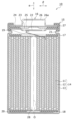
- FIG. 1 is a cross-sectional view of a cylindrical secondary battery as an example of an embodiment
- FIG. FIG. 3 is a diagram showing a part of the wound body that constitutes the cylindrical secondary battery of the embodiment by developing it.
- FIG. 3 is a cross-sectional view of the positive electrode plate of FIG. 2 taken along the line AA.
- FIG. 5 is a diagram showing a part of a wound body that constitutes a cylindrical secondary battery of a comparative example in a developed state. 5 is a cross-sectional view of the positive electrode plate of FIG. 4 taken along the line BB.
- FIG. FIG. 4 is a view corresponding to FIG. 3 in a positive electrode plate of another example of the embodiment;
- FIG. 4 is a view corresponding to FIG.
- FIG. 10 is a diagram schematically showing that the arrangement position of a positive electrode tab, which is a current-collecting metal tab, is changed in a developed view of a positive electrode plate of another example of the embodiment.
- FIG. 10 is a diagram showing the results of a test conducted to confirm the effect obtained with the configuration of FIG. 9;
- FIG. 4 is an image diagram showing the relationship between the difference in the arrangement position of the positive electrode tab inside the secondary battery and the magnitude of the effect of improving foil breakage in the positive electrode core in the embodiment.
- FIG. 10 is a plan view of the positive electrode tab in the embodiment and another example when viewed from the thickness direction.
- FIG. 1 is a cross-sectional view of a cylindrical secondary battery 10 according to an embodiment.
- FIG. 2 is a partially developed view of the wound body 14 that constitutes the cylindrical secondary battery 10.
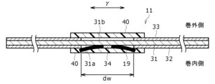
- FIG. 3 is a cross-sectional view of the positive plate 11 of FIG. 2 taken along the line AA.
- a cylindrical secondary battery 10 includes a winding body 14 , a non-aqueous electrolyte (not shown), a case body 15 and a sealing body 16 .
- a “cylindrical secondary battery” is hereinafter referred to as a "secondary battery.”
- the wound body 14 has a positive electrode plate 11 , a negative electrode plate 12 , and a separator 13 , and the positive electrode plate 11 and the negative electrode plate 12 are spirally wound with the separator 13 interposed therebetween.
- the positive plate 11 and the negative plate 12 respectively correspond to electrode plates.
- one axial side of the wound body 14 may be referred to as “upper”, and the other axial side may be referred to as "lower”.
- the non-aqueous electrolyte contains a non-aqueous solvent and an electrolyte salt dissolved in the non-aqueous solvent.
- the non-aqueous electrolyte is not limited to a liquid electrolyte, and may be a solid electrolyte using a gel polymer or the like.
- the positive electrode plate 11 has a strip-shaped positive electrode core 31 and a positive electrode tab 19 joined to the positive electrode core 31 .
- the positive electrode tab 19 corresponds to a current collecting metal tab.
- the positive electrode tab 19 is a conductive member for electrically connecting the positive electrode core 31 and the positive electrode terminal. procrastinating. A connection configuration between the positive electrode tab 19 and the positive electrode plate 11 will be described later in detail.
- the positive electrode tab 19 is a strip-shaped conductive member.
- the constituent material of the positive electrode tab is not particularly limited.
- the positive electrode tab 19 is preferably made of metal containing aluminum as a main component.
- the positive electrode plate 11 has positive electrode active material mixture layers 32 and 33 formed on the winding inner side (inside in the radial direction ⁇ ) and the winding outer side (outside in the radial direction ⁇ ) of the positive electrode core 31, respectively.
- the positive electrode active material mixture layer 32 on the inner side of the roll is indicated by a diagonal lattice portion.
- the negative electrode plate 12 has a strip-shaped negative electrode core 35 and a negative electrode tab 20 (FIG. 1) joined to the negative electrode core 35 .
- the negative electrode tab 20 is a conductive member for electrically connecting the negative electrode core 35 and a case main body 15 to be described later. (downward).
- the case main body 15 serves as a negative terminal.
- the negative electrode tab 20 is provided, for example, on the winding outer side portion (peripheral surface side portion) of the wound body 14 .
- the negative electrode tab 20 is a strip-shaped conductive member.
- the constituent material of the negative electrode tab is not particularly limited.
- the negative electrode tab is preferably constructed with a nickel- or copper-based metal, or with a metal containing both nickel and copper.
- the negative electrode tabs may be provided at multiple positions on the negative electrode core 35 . Further, in the negative electrode plate 12 , a negative electrode active material layer (not shown) is formed on each of the winding inner side (radial direction inner side) and the winding outer side (radial direction outer side) of the negative electrode core 35 .
- the negative electrode core is exposed on the outermost peripheral surface of the wound body 14 to form an exposed portion, and the exposed portion is brought into contact with the inner surface of the cylindrical portion of the case body 15 to be electrically connected to the case body 15. You may At this time, the electrical connection between the negative electrode plate 12 and the cylindrical portion of the case body 15 ensures better current collection.
- the wound body 14 has a wound structure in which the positive electrode plate 11 and the negative electrode plate 12 are spirally wound with the separator 13 interposed therebetween.
- the positive electrode plate 11 , the negative electrode plate 12 , and the separator 13 are all formed in a strip shape, and are spirally wound to be alternately stacked in the radial direction ⁇ of the wound body 14 .
- the longitudinal direction of each electrode plate 11, 12 is the winding direction ⁇ (FIG. 2)
- the width direction of each electrode plate 11, 12 is the axial direction ⁇ (FIG. 1).
- a space 28 is formed in a core portion including the core of the wound body 14 .
- the wound body 14 is spirally wound around a winding central axis O extending in the axial direction at the center of the space 28 .
- the winding central axis O is the central axis extending in the axial direction at the center position in the diametrical direction of the space 28 and is the winding core of the wound body 14 .
- a winding stop tape (not shown) is attached to the outermost peripheral surface of the wound body 14 so as to straddle the end of winding in the winding direction of the wound body 14 so as to fix the end of winding of the wound body 14 . be.
- the case main body 15 and the sealing member 16 constitute a metal battery case that accommodates the winding body 14 and the non-aqueous electrolyte.
- Insulating plates 17 and 18 are provided above and below the wound body 14, respectively.
- the positive electrode tab 19 extends through the through hole of the upper insulating plate 17 toward the sealing member 16 and is welded to the lower surface of the filter 22 which is the bottom plate of the sealing member 16 .
- the cap 26, which is the top plate of the sealing member 16 electrically connected to the filter 22, serves as a positive electrode terminal.
- the case main body 15 is a bottomed cylindrical container having an opening, for example, a bottomed cylindrical metal container.
- a gasket 27 is provided between the case main body 15 and the sealing member 16 to ensure hermeticity in the battery case.
- the case main body 15 has an overhanging portion 21 that supports the sealing member 16 and is formed, for example, by pressing the side portion from the outside.
- the protruding portion 21 is preferably annularly formed along the circumferential direction of the case body 15 and supports the sealing member 16 on the upper surface thereof.
- the sealing member 16 seals the opening of the case body 15 .
- the sealing body 16 has a filter 22, a lower valve body 23, an insulating member 24, an upper valve body 25, and a cap 26, which are stacked in order from the winding body 14 side.
- Each member constituting the sealing member 16 has, for example, a disk shape or a ring shape, and each member other than the insulating member 24 is electrically connected to each other.
- the lower valve body 23 and the upper valve body 25 are connected to each other at their central portions, and an insulating member 24 is interposed between their peripheral edge portions.
- the constituent elements of the wound body 14, particularly the positive electrode plate 11 and the positive electrode tab 19, will be described in detail below with reference to FIGS.
- a foil of a metal such as aluminum, a film having the metal on the surface layer, or the like is used for the positive electrode core 31 of the positive electrode plate 11.
- a suitable positive electrode core 31 is a metal foil whose main component is aluminum or an aluminum alloy.
- the thickness of the positive electrode core 31 is, for example, 10 ⁇ m to 30 ⁇ m.
- the positive electrode active material mixture layers 32 and 33 preferably contain a positive electrode active material, a conductive agent, and a binder.
- the positive electrode plate 11 is formed by applying a positive electrode mixture slurry containing a positive electrode active material, a conductive agent, a binder, and a solvent such as N-methyl-2-pyrrolidone (NMP) to both surfaces of the positive electrode core 31, followed by drying and It is produced by rolling.
- NMP N-methyl-2-pyrrolidone
- positive electrode active materials include lithium-containing transition metal oxides containing transition metal elements such as Co, Mn, and Ni.
- the lithium-containing transition metal oxide is not particularly limited, but has the general formula Li 1+x MO 2 (where ⁇ 0.2 ⁇ x ⁇ 0.2, M includes at least one of Ni, Co, Mn and Al). It is preferably a composite oxide represented by.
- Examples of the conductive agent include carbon black (CB), acetylene black (AB), ketjen black, graphite and other carbon materials.
- Examples of the binder include fluorine-based resins such as polytetrafluoroethylene (PTFE) and polyvinylidene fluoride (PVdF), polyacrylonitrile (PAN), polyimide (PI), acrylic resins, and polyolefin-based resins. be done. Further, these resins may be used in combination with carboxymethyl cellulose (CMC) or salts thereof, polyethylene oxide (PEO), and the like. These may be used individually by 1 type, and may be used in combination of 2 or more types.
- Core body exposed portions 31a and 31b are provided, the surfaces of which are exposed.
- Each core exposed part 31a, 31b is a portion formed in a rectangular shape over the entire width direction of the positive electrode core 31, and is a portion where the surface of the positive electrode core 31 is not covered with the positive electrode active material mixture layer. be.
- the two core exposed portions 31 a and 31 b are formed at the same position in the winding direction ⁇ of the positive electrode core 31 .
- Widths dw (FIG. 3) along the winding direction ⁇ of the respective core exposed portions 31a and 31b are the same.
- the positive electrode tab 19 is arranged on the inner core exposed portion 31a of the positive electrode core 31, and is electrically connected to the positive electrode core 31 by welding such as ultrasonic welding.
- the positive electrode tab 19 has an elongated rectangular plate shape. For this reason, the shapes of both ends of the positive electrode tab 19 in the width direction are straight lines parallel to each other when the positive electrode tab 19 is viewed in the thickness direction.
- the width of the positive electrode tab 19 corresponding to the winding direction ⁇ before joining to the positive electrode core 31 is larger than the width dw of the core exposed portion 31a.
- the positive electrode tab 19 is curved such that the center in the width direction is convex toward the exposed core portion 31 a at least at the longitudinal end facing the positive electrode plate 11 . Then, the positive electrode tab 19 is welded to the positive electrode core 31 in a state in which the center portion of the positive electrode tab 19 in the width direction is in contact with the winding inner surface of the positive electrode core 31 .
- the sanded portion indicates the melted and solidified portion 34 during welding of the positive electrode tab 19 .
- both ends of the positive electrode tab 19 in the width direction run over the ends of the positive electrode active material mixture layer 32 provided on the winding inner surface of the positive electrode core 31 . Accordingly, the positive electrode active material mixture layer 32 is interposed between both ends of the positive electrode tab 19 in the width direction and the positive electrode core 31 , and both ends of the positive electrode tab 19 in the width direction and the positive electrode core 31 are in contact with each other. not. As will be described later, this makes it possible to prevent foil breakage of the positive electrode core 31 regardless of repeated charging and discharging of the secondary battery 10 .
- an insulating tape 40 is attached to the surface of the positive electrode tab 19 opposite to the positive electrode core 31 side and to the portions of the positive electrode active material mixture layer 32 located on both sides of the core exposed portion 31a in the winding direction ⁇ . be.
- the insulating tape 40 covers the longitudinal end portion of the positive electrode tab 19 on the side of the positive electrode core 31 and also covers the core exposed portion 31a.
- the insulating tape 40 is provided to protect the positive electrode tab 19 and the exposed core portion 31a.
- the insulating tape 40 prevents a short circuit in the wound body 14 due to adherence of conductive foreign matter to the positive electrode tab 19 .
- the insulating tape 40 is also attached to portions of the positive electrode active material mixture layer 33 on the outer side of the winding of the positive electrode core 31, which are positioned on both sides of the core exposed portion 31b in the winding direction ⁇ .
- the insulating tape 40 is made of an insulating material such as PI tape.
- a PI tape has an adhesive layer formed on one surface of a substrate layer such as polyimide (PI).
- PI polyimide
- PP polypropylene
- PET polyethylene terephthalate
- PP polypropylene
- PET polyethylene terephthalate
- the negative electrode plate 12 has a negative electrode core 35 and a negative electrode active material mixture layer (not shown) formed on the negative electrode core 35 .
- a negative electrode core 35 for example, a foil of a metal such as copper, a film having a surface layer of the metal, or the like is used.
- the thickness of the negative electrode core 35 is, for example, 5 ⁇ m to 30 ⁇ m.
- the negative electrode active material mixture layer preferably contains a negative electrode active material and a binder.
- the negative electrode plate 12 is produced by, for example, applying a negative electrode mixture slurry containing a negative electrode active material, a binder, water, etc. to both surfaces of the negative electrode core 35, followed by drying and rolling.
- the negative electrode active material is not particularly limited as long as it can reversibly occlude and release lithium ions.
- An alloy containing, a composite oxide, or the like can be used.
- the binder contained in the negative electrode active material layer for example, the same resin as in the case of the positive electrode plate 11 is used.
- SBR styrene-butadiene rubber
- CMC polyacrylic acid or its salt
- polyvinyl alcohol or the like
- a porous sheet having ion permeability and insulation is used for the separator 13 (FIGS. 1 and 2).
- porous sheets include microporous thin films, woven fabrics, and non-woven fabrics.
- an olefin resin such as polyethylene or polypropylene is preferable.
- the thickness of the separator 13 is, for example, 10 ⁇ m to 50 ⁇ m.
- the separator 13 has a melting point of about 130.degree. C. to 180.degree. C., for example.
- the positive electrode active material mixture layer 32 is interposed between both ends of the positive electrode tab 19 in the width direction and the positive electrode core 31 .
- the expansion and contraction of the electrode plates 11 and 12 are repeated due to repeated charging and discharging of the secondary battery 10, and even when the surface pressure applied to the electrode plates 11 and 12 tends to increase, the positive electrode tab 19 does not.
- the pressure that the positive electrode core 31 receives from both ends in the width direction can be suppressed. Therefore, even if the secondary battery 10 is repeatedly charged and discharged, it is possible to suppress foil breakage of the positive electrode core 31 .
- the positive electrode active material mixture layer 32 is interposed between both widthwise ends of the positive electrode tab 19 and the positive electrode core 31 .
- the positive electrode active material mixture layer 32 may not be interposed between the positive electrode core 31 and both ends in the width direction over the entire length. It is preferable that the positive electrode active material mixture layer 32 is interposed between at least a portion of each of the widthwise ends of the positive electrode tab 19 and the positive electrode core 31, but one end of the widthwise both ends of the positive electrode tab 19 (widthwise It is sufficient that the positive electrode active material mixture layer 32 is interposed between at least a part of the edge) and the positive electrode core 31 .
- the width direction end of the positive electrode tab 19 may be in contact with the positive electrode active material mixture layer 32 , it should be separated from the positive electrode active material mixture layer 32 without contacting the positive electrode active material mixture layer 32 . good too.
- the positive electrode tab 19 is welded to the core exposed portion 31a and electrically connected, it may be electrically connected by, for example, contacting the core exposed portion 31a other than welding.
- the width dw of the exposed core portion 31a which is the interval between the positive electrode active material mixture layers 32 on both sides of the exposed core portion 31a of the positive electrode core 31, can be reduced.
- the width of the insulating tape 40 for protecting the welded area of the tab 19 can be reduced.
- the cost of the insulating tape 40 can be reduced, and the area of the positive electrode active material mixture layer 32 can be increased, so that the battery performance can be improved.
- the current-collecting metal tab in the case where the active material mixture layer is interposed between at least a part of the width direction end of the current-collecting metal tab and the core body is an electrical
- the positive electrode tab 19 is positively connected.
- the positive electrode core 31 is often made of a metal foil containing an aluminum alloy as a main component, and is softer than the negative electrode plate 12, which is often formed of a metal foil such as copper or a film having the metal on its surface. Easy to cut. As a result, the configuration of the present disclosure has a remarkable effect of suppressing foil breakage of the core.
- FIG. 4 shows a part of the wound body 14a that constitutes the secondary battery of the comparative example.
- FIG. 5 is a BB cross-sectional view of the positive electrode plate 11 of FIG.
- the width Wt of the positive electrode tab 19 is smaller than the width dw of the exposed core portion 31a.
- the positive electrode tab 19 is arranged such that the entire surface of the positive electrode plate 11 side at the end on the positive electrode core 31 side in the longitudinal direction is disposed in the core exposed portion 31a on the inner side of the winding of the positive electrode core 31, and the positive electrode tab 19 is positioned on the positive electrode core. It is joined to the core body 31 by welding. As a result, the positive electrode active material mixture layer 32 does not intervene between both ends of the positive electrode tab 19 in the width direction and the positive electrode core 31 .
- the surface pressure applied to each of the electrode plates 11 and 12 increases as the electrode plates 11 and 12 repeatedly expand and contract during the charging and discharging cycles of the secondary battery including the wound body 14a.
- the pressure that the positive electrode core 31 receives from both ends in the width direction of the positive electrode tab 19 may increase.
- the foil of the positive electrode core 31 will be cut. According to the embodiments of FIGS. 1 to 3, the occurrence of foil breakage can be suppressed.
- FIG. 6 is a diagram corresponding to FIG. 3 in the positive electrode plate 11 of another example of the embodiment.
- the width dwa along the winding direction ⁇ of the outer core exposed portion 31b of the positive electrode plate 11 is larger than the width dw along the winding direction ⁇ of the inner core exposed portion 31a.
- the central positions of the two core exposed portions 31a and 31b in the winding direction ⁇ coincide with each other.
- the pressure that the positive electrode plate 11 receives from both ends of the positive electrode tab 19 in the width direction due to charging and discharging of the secondary battery can be further suppressed. That is, on the outer side of the positive electrode plate 11, a gap G1 corresponding to the thickness of the positive electrode active material mixture layer 33 is provided in a portion on the opposite side with respect to both width direction ends of the positive electrode tab 19 and the positive electrode core 31. The pressure applied to the positive electrode core 31 from both ends of the tab 19 in the width direction can be distributed. This makes it possible to obtain a secondary battery that can further suppress foil breakage of the positive electrode core 31 .
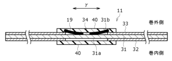
- FIG. 7 is a diagram corresponding to FIG. 3 in the positive electrode plate 11 of another example of the embodiment.
- the core exposed portion 31a on the inner side of the winding of the positive electrode core 31 in the configuration of FIGS. It is welded and electrically connected to the body 31 .
- the positive electrode tab 19 is welded to the positive electrode core 31 in a state in which the center portion in the width direction is in contact with the winding outer surface of the positive electrode core 31 .
- both ends of the positive electrode tab 19 in the width direction run over the ends of the positive electrode active material mixture layer 33 provided on the winding outer side of the positive electrode core 31 .
- the positive electrode active material mixture layer 33 is interposed between at least a part of both ends in the width direction of the positive electrode tab 19 and the positive electrode core 31, and both ends in the width direction of the positive electrode tab 19 and the positive electrode core No contact with 31.
- the positive electrode tab 19 is arranged on the outer side of the positive electrode core 31 that is bent inward in the wound state. As a result, compared with the case where the positive electrode tab 19 is arranged on the inner side of the winding of the positive electrode core 31 , the pressure applied to the positive electrode plate 11 from both ends in the width direction of the positive electrode tab 19 is reduced. As a result, foil breakage of the positive electrode core 31 can be further suppressed.
- other configurations and actions are the same as those in FIGS. 1 to 3. FIG.
- FIG. 8 is a diagram corresponding to FIG. 3 in the positive electrode plate 11 of another example of the embodiment.
- the width dw of the core exposed portion 31a on the inner side of the positive electrode plate 11 along the winding direction ⁇ is the width dw along the winding direction ⁇ of the core exposed portion 31b on the outer side of the winding. It is larger than the width dwa.
- the central positions of the two core exposed portions 31a and 31b in the winding direction coincide with each other.
- the configuration of this example it is possible to suppress the pressure that the positive electrode plate 11 receives from the width direction end of the positive electrode tab 19 due to charging and discharging of the secondary battery. That is, on the inner side of the winding of the positive electrode plate 11, a gap G2 corresponding to the thickness of the positive electrode active material mixture layer 32 is provided in the portion opposite to the widthwise ends of the positive electrode tab 19 with respect to the positive electrode core 31.
- the pressure applied to the positive electrode core 31 from both ends of the tab 19 in the width direction can be dispersed. This makes it possible to obtain a secondary battery that can further suppress foil breakage of the positive electrode core 31 .
- Other configurations and actions in this example are the same as the configuration in FIGS. 1 to 3, the configuration in FIG. 6, or the configuration in FIG.
- FIG. 9 schematically shows that the arrangement position of the positive electrode tab 19 is changed in the developed view of the positive electrode plate 11 of another example of the embodiment.
- 50% and 35% which are the ratios shown below the positive electrode tab 19 represent the ratio of the length from the winding start end to the position of the positive electrode tab 19 with respect to the total length of the positive electrode plate 11 along the winding direction ⁇ . showing. Therefore, it is 0% at the winding start end of the positive electrode plate 11 and 100% at the winding end end.
- the arrangement position of the positive electrode tab 19 is not limited to the position where the ratio of the length from the winding start to the positive electrode tab is 35%, but can be a position between 0% and 50%.
- the distance from the inner peripheral surface of the highly rigid case body 15 (FIG. 1) to the positive electrode tab 19 is long.
- the surface pressure applied to the positive electrode tab 19 when the wound body expands during charging and discharging of the secondary battery can be made smaller, so that the foil breakage of the positive electrode core 31 can be further suppressed.
- Other configurations and actions in this example are the same as those in FIGS.
- the configuration of this example may be combined with the configuration of FIG. 7 in which the positive electrode tab 19 is arranged on the outer side of the winding of the positive electrode core.
- FIG. 10 shows the results of an experiment conducted to confirm the effects obtained with the configuration of FIG.
- the same configuration as the comparative example shown in FIGS. 4 and 5 was used with the tab position set at 50%, and the layout position of the positive electrode tab 19 was changed from that configuration toward the winding start end of the positive electrode plate 11. was configured to have a tab position of 45%, a tab position of 40%, and a tab position of 35%.
- the ratio of the tab position means the ratio of the length from the winding start end to the position of the positive electrode tab 19 with respect to the total length of the positive electrode plate along the winding direction ⁇ , as in the configuration shown in FIG.
- the secondary battery 10 was disassembled to check the state of foil breakage near the positive electrode tabs 19 of the positive electrode core 31. .
- FIG. 10 photographs of X-ray computed tomography images (X-ray CT images) of the secondary battery 10 are schematically shown.
- the positive electrode tab is arranged inside the arc-shaped space at the tip of the thick arrow.
- 10 schematically shows a portion of the positive electrode plate 11 including the arrangement position of the positive electrode tab 19.
- the length of the foil cut arrow indicates the location and length of the cut foil.
- the shape and size of the foil strip are indicated by the L-shaped foil strip.
- FIG. 11 is an image diagram showing the relationship between the difference in the arrangement position of the positive electrode tab 19 inside the secondary battery 10 and the magnitude of the effect of improving foil breakage in the positive electrode core in the embodiment.
- FIGS. 11A to 11D schematically show the positional relationship between a part of the positive electrode plate 11 inside the wound body 14 and the positive electrode tab 19 joined to the part.
- a positive electrode tab 19 is arranged on the winding inner side of the positive electrode plate 11, as in the configuration of FIGS.
- FIG. 11(b) the arrangement position of the positive electrode tab 19 is changed to the winding start end side of the positive electrode plate 11 from (a).
- FIG. 11C the position of the positive electrode tab 19 in the winding direction of the positive electrode plate 11 is the same as in FIG. 11D
- the position of the positive electrode tab 19 in the winding direction of the positive electrode plate 11 is the same as in FIG.
- FIG. 12 is a plan view of the positive electrode tab viewed from the thickness direction in the embodiment and another example.
- FIG. 12(a) is a plan view of the positive electrode tab 19 of the embodiment
- FIGS. 12(b) to 12(f) are plan views of different positive electrode tabs 19a to 19e, respectively.
- both ends in the width direction of the positive electrode tabs 19 and 19a are linear
- both ends in the width direction of the positive electrode tab 19a are They are inclined with respect to the longitudinal direction so as to gradually approach each other toward one side in the longitudinal direction (lower side in FIG. 12(b)).
- FIGS. 12(c) and 12(d) are plan views of the positive electrode tabs 19b and 19c, respectively, and both ends of the positive electrode tabs 19b and 19c in the width direction are curved. Both ends of the positive electrode tabs 19c and 19d in the width direction have a shape in which two circular arcs 41 are connected and a shape in which four circular arcs 42 are connected.
- FIGS. 12(e) and 12(f) are plan views of the positive electrode tabs 19d and 19e, and both ends in the width direction of the positive electrode tabs 19d and 19e have shapes in which a plurality of straight lines 43 and 44 are combined. Both ends in the width direction of the positive electrode tab 19d have a zigzag shape with four corners. Both ends of the positive electrode tab 19e in the width direction are mountain-shaped by combining two straight lines 44. As shown in FIG.
- the positive electrode tabs 19, 19a to 19e shown in FIGS. 12(a) to 12(f) are used, part of both ends in the width direction of the positive electrode tabs 19, 19a to 19e largely protrude outward in the width direction.
- the positive electrode tabs 19, 19a to 19e may be configured to run over the positive electrode active material mixture layers on both sides in the winding direction.
- the positive electrode active material mixture layer is interposed between a portion of both ends in the width direction of the positive electrode tabs 19, 19a to 19e and the positive electrode core.
- Such a configuration of another example can also suppress foil breakage of the positive electrode core.
- the positive electrode tabs 19 and 19a to 19c do not have sharp corners at both ends in the width direction. As a result, even when the surface pressure applied to the positive electrode tabs 19, 19a to 19e and the positive electrode plate in the rolled state increases, the foil breakage of the positive electrode core can be further suppressed.
- Example 1 Preparation of positive electrode plate
- a predetermined known pasty positive electrode mixture slurry is applied to both sides of a long positive electrode core made of aluminum foil, dried in a dryer, cut into a predetermined electrode size, and rolled using a roller.
- a positive electrode plate 11 was prepared by forming positive electrode active material mixture layers on both sides of a positive electrode core.
- a core exposed portion where no active material is formed was formed in the center of the positive electrode plate 11 in the length direction, and an aluminum positive electrode tab 19 was fixed to the core exposed portion on the inner side of the roll by ultrasonic welding.
- the positive electrode tab 19 has a width of 5.0 mm, a length of 68.0 mm, and a thickness of 0.10 mm.
- Both ends of the positive electrode tab 19 in the width direction were arranged so as to ride on the positive electrode active material mixture layer on the foil portion of the positive electrode core.
- the positive electrode plate 11 has a width of 58.0 mm, a length of 938.0 mm, and a thickness of 0.10 mm.
- a predetermined known negative electrode mixture slurry was applied to both surfaces of a negative electrode core made of copper foil, dried with a dryer, and compressed to a predetermined thickness with rollers of a roll press. Then, after cutting the elongated negative electrode core on which the negative electrode active material layer was formed into a predetermined electrode size, a negative electrode tab made of a copper-nickel clad material was attached. At this time, an exposed core portion having no active material formed on both sides was formed at one end in the winding direction of the negative electrode core, and the negative electrode tab was fixed to the exposed core portion by ultrasonic welding.
- a core exposed portion where no active material was formed on both sides was formed, and the negative electrode tab was also fixed to the core exposed portion by ultrasonic welding.
- One negative tab was 3.0 mm wide, 52.0 mm long and 0.10 mm thick, and the other negative tab was 3.0 mm wide, 61.0 mm long and 0.1 mm thick. 10 mm.
- the negative plate has a width of 59.0 mm, a length of 1040.0 mm, and a thickness of 0.10 mm. Thus, a negative electrode plate 12 was produced.
- the separator 13 has a width of 62.0 mm, lengths of 1114.0 mm and 1134.0 mm, and a thickness of 0.014 mm.
- the above wound body is housed in a bottomed cylindrical case body 15 having an outer diameter of 18 mm and a height of 65 mm.
- a non-aqueous electrolyte was injected into the inside of the After that, the open end of the case body 15 was sealed with the gasket 27 and the sealing member 16 to fabricate a cylindrical lithium ion secondary battery of 18650 size. After the secondary battery was produced, a charge/discharge test was performed.
- Example 1 and Comparative Example 1 were charged to 4.2V and then discharged to 2.5V. After charging and discharging, the wound body was taken out from the case main body of each secondary battery, and the presence or absence of foil breakage of the positive electrode core was checked in the vicinity of the joint between the positive electrode tab and the positive electrode core. The results are shown in Table 1 below. Experiments were carried out on three specimens for each of Example 1 and Comparative Example 1. In addition, it was confirmed that there was no foil breakage of the positive electrode substrate before charging and discharging in each test sample.
- Example 2 In Example 2, similarly to the configuration shown in FIG. 7, the positive electrode tab was fixed to the core exposed portion on the winding outer side of the positive electrode core by ultrasonic welding.
- Other configurations in the second embodiment are the same as those in the first embodiment.
- Example 2 and Comparative Example 1 The fabricated secondary batteries of Example 2 and Comparative Example 1 were charged to 4.2V and then discharged to 2.5V. After charging and discharging, the wound body was taken out from the case main body of each battery, and the presence or absence of foil breakage of the positive electrode core was checked in the vicinity of the junction between the positive electrode tab and the positive electrode core. The results are shown in Table 2 below. Experiments were carried out on two specimens in each of Example 2 and Comparative Example 1. In addition, it was confirmed that the core foil was not broken before charging and discharging in each test product.
- the configuration of the present disclosure is applied to the configuration in which the positive electrode tab is connected to the positive electrode plate, but the configuration of the present disclosure may be applied to the configuration in which the negative electrode tab is connected to the negative electrode plate. . That is, the negative electrode active material mixture layer may be interposed between at least a portion of the widthwise end of the negative electrode tab and the negative electrode core.
Landscapes
- Chemical & Material Sciences (AREA)
- Chemical Kinetics & Catalysis (AREA)
- Electrochemistry (AREA)
- General Chemical & Material Sciences (AREA)
- Engineering & Computer Science (AREA)
- Manufacturing & Machinery (AREA)
- Secondary Cells (AREA)
- Connection Of Batteries Or Terminals (AREA)
Priority Applications (4)
| Application Number | Priority Date | Filing Date | Title |
|---|---|---|---|
| CN202280073148.0A CN118216031A (zh) | 2021-11-12 | 2022-11-10 | 圆筒形二次电池 |
| EP22892863.6A EP4432417A4 (en) | 2021-11-12 | 2022-11-10 | CYLINDRICAL SECONDARY BATTERY |
| US18/706,664 US20250015360A1 (en) | 2021-11-12 | 2022-11-10 | Cylindrical secondary battery |
| JP2023559899A JPWO2023085365A1 (https=) | 2021-11-12 | 2022-11-10 |
Applications Claiming Priority (2)
| Application Number | Priority Date | Filing Date | Title |
|---|---|---|---|
| JP2021184735 | 2021-11-12 | ||
| JP2021-184735 | 2021-11-12 |
Publications (1)
| Publication Number | Publication Date |
|---|---|
| WO2023085365A1 true WO2023085365A1 (ja) | 2023-05-19 |
Family
ID=86335863
Family Applications (1)
| Application Number | Title | Priority Date | Filing Date |
|---|---|---|---|
| PCT/JP2022/041933 Ceased WO2023085365A1 (ja) | 2021-11-12 | 2022-11-10 | 円筒形二次電池 |
Country Status (5)
| Country | Link |
|---|---|
| US (1) | US20250015360A1 (https=) |
| EP (1) | EP4432417A4 (https=) |
| JP (1) | JPWO2023085365A1 (https=) |
| CN (1) | CN118216031A (https=) |
| WO (1) | WO2023085365A1 (https=) |
Families Citing this family (1)
| Publication number | Priority date | Publication date | Assignee | Title |
|---|---|---|---|---|
| WO2026044769A1 (zh) * | 2024-08-31 | 2026-03-05 | 宁德新能源科技有限公司 | 二次电池及用电设备 |
Citations (6)
| Publication number | Priority date | Publication date | Assignee | Title |
|---|---|---|---|---|
| JPH11242961A (ja) * | 1998-02-25 | 1999-09-07 | Sanyo Electric Co Ltd | 非水電解液電池の製造方法 |
| JP2006260892A (ja) * | 2005-03-16 | 2006-09-28 | Dainippon Printing Co Ltd | 非水電解液二次電池用電極板、その製造方法、及び非水電解液二次電池 |
| JP2007087842A (ja) * | 2005-09-26 | 2007-04-05 | Sanyo Electric Co Ltd | リチウム二次電池及びその製造方法 |
| JP2009164164A (ja) * | 2007-12-28 | 2009-07-23 | Elna Co Ltd | 電極素子の製造方法および同電極素子を備えた蓄電用電気化学デバイス |
| JP2013048176A (ja) * | 2011-08-29 | 2013-03-07 | Tdk Corp | 巻回型電気化学デバイス |
| WO2019193870A1 (ja) | 2018-04-06 | 2019-10-10 | パナソニックIpマネジメント株式会社 | 非水電解質二次電池の巻回型電極体、及び非水電解質二次電池 |
Family Cites Families (2)
| Publication number | Priority date | Publication date | Assignee | Title |
|---|---|---|---|---|
| WO2019082748A1 (ja) * | 2017-10-27 | 2019-05-02 | 三洋電機株式会社 | 非水電解質二次電池の製造方法 |
| WO2019194181A1 (ja) * | 2018-04-06 | 2019-10-10 | 三洋電機株式会社 | 非水電解質二次電池 |
-
2022
- 2022-11-10 JP JP2023559899A patent/JPWO2023085365A1/ja active Pending
- 2022-11-10 US US18/706,664 patent/US20250015360A1/en active Pending
- 2022-11-10 EP EP22892863.6A patent/EP4432417A4/en active Pending
- 2022-11-10 CN CN202280073148.0A patent/CN118216031A/zh active Pending
- 2022-11-10 WO PCT/JP2022/041933 patent/WO2023085365A1/ja not_active Ceased
Patent Citations (6)
| Publication number | Priority date | Publication date | Assignee | Title |
|---|---|---|---|---|
| JPH11242961A (ja) * | 1998-02-25 | 1999-09-07 | Sanyo Electric Co Ltd | 非水電解液電池の製造方法 |
| JP2006260892A (ja) * | 2005-03-16 | 2006-09-28 | Dainippon Printing Co Ltd | 非水電解液二次電池用電極板、その製造方法、及び非水電解液二次電池 |
| JP2007087842A (ja) * | 2005-09-26 | 2007-04-05 | Sanyo Electric Co Ltd | リチウム二次電池及びその製造方法 |
| JP2009164164A (ja) * | 2007-12-28 | 2009-07-23 | Elna Co Ltd | 電極素子の製造方法および同電極素子を備えた蓄電用電気化学デバイス |
| JP2013048176A (ja) * | 2011-08-29 | 2013-03-07 | Tdk Corp | 巻回型電気化学デバイス |
| WO2019193870A1 (ja) | 2018-04-06 | 2019-10-10 | パナソニックIpマネジメント株式会社 | 非水電解質二次電池の巻回型電極体、及び非水電解質二次電池 |
Non-Patent Citations (1)
| Title |
|---|
| See also references of EP4432417A4 |
Also Published As
| Publication number | Publication date |
|---|---|
| CN118216031A (zh) | 2024-06-18 |
| US20250015360A1 (en) | 2025-01-09 |
| JPWO2023085365A1 (https=) | 2023-05-19 |
| EP4432417A1 (en) | 2024-09-18 |
| EP4432417A4 (en) | 2025-07-09 |
Similar Documents
| Publication | Publication Date | Title |
|---|---|---|
| JP7035017B6 (ja) | 非水電解質二次電池 | |
| JP7321158B2 (ja) | 非水電解質二次電池 | |
| JP7263340B2 (ja) | 非水電解質二次電池 | |
| JP7317823B2 (ja) | 非水電解質二次電池 | |
| US11502382B2 (en) | Nonaqueous electrolyte secondary battery | |
| WO2018079291A1 (ja) | 非水電解質二次電池用電極及び非水電解質二次電池 | |
| JPWO2018173899A1 (ja) | 非水電解質二次電池 | |
| WO2018168628A1 (ja) | 非水電解質二次電池 | |
| JP7102348B2 (ja) | 液体電解質含有非水電解質二次電池用正極及び液体電解質含有非水電解質二次電池 | |
| JP6953422B2 (ja) | 非水電解質二次電池用電極及び非水電解質二次電池 | |
| WO2023100756A1 (ja) | 非水電解質二次電池 | |
| WO2023171600A1 (ja) | 非水電解質二次電池 | |
| WO2023085365A1 (ja) | 円筒形二次電池 | |
| WO2023210640A1 (ja) | 二次電池 | |
| EP4583298A1 (en) | Cylindrical battery | |
| US20250046920A1 (en) | Cylindrical secondary battery | |
| WO2024181017A1 (ja) | 二次電池 | |
| WO2025028428A1 (ja) | 二次電池 | |
| WO2025225437A1 (ja) | 非水電解質二次電池 | |
| WO2025205805A1 (ja) | 非水電解質二次電池 | |
| WO2023182170A1 (ja) | 円筒形非水電解質二次電池 | |
| WO2026071149A1 (ja) | 非水電解質二次電池 | |
| WO2025248929A1 (ja) | 非水電解質二次電池 | |
| WO2026028648A1 (ja) | 円筒形電池および円筒形電池用正極の製造方法 | |
| WO2026014340A1 (ja) | 非水電解質二次電池及び非水電解質二次電池用負極の製造方法 |
Legal Events
| Date | Code | Title | Description |
|---|---|---|---|
| 121 | Ep: the epo has been informed by wipo that ep was designated in this application |
Ref document number: 22892863 Country of ref document: EP Kind code of ref document: A1 |
|
| WWE | Wipo information: entry into national phase |
Ref document number: 202280073148.0 Country of ref document: CN |
|
| ENP | Entry into the national phase |
Ref document number: 2023559899 Country of ref document: JP Kind code of ref document: A |
|
| WWE | Wipo information: entry into national phase |
Ref document number: 18706664 Country of ref document: US |
|
| WWE | Wipo information: entry into national phase |
Ref document number: 202417035010 Country of ref document: IN |
|
| WWE | Wipo information: entry into national phase |
Ref document number: 2022892863 Country of ref document: EP |
|
| NENP | Non-entry into the national phase |
Ref country code: DE |
|
| ENP | Entry into the national phase |
Ref document number: 2022892863 Country of ref document: EP Effective date: 20240612 |