WO2023085305A1 - Cu-Ag系合金線 - Google Patents
Cu-Ag系合金線 Download PDFInfo
- Publication number
- WO2023085305A1 WO2023085305A1 PCT/JP2022/041680 JP2022041680W WO2023085305A1 WO 2023085305 A1 WO2023085305 A1 WO 2023085305A1 JP 2022041680 W JP2022041680 W JP 2022041680W WO 2023085305 A1 WO2023085305 A1 WO 2023085305A1
- Authority
- WO
- WIPO (PCT)
- Prior art keywords
- mass
- alloy wire
- phase
- wire
- content
- Prior art date
- Legal status (The legal status is an assumption and is not a legal conclusion. Google has not performed a legal analysis and makes no representation as to the accuracy of the status listed.)
- Ceased
Links
Images


Classifications
-
- H—ELECTRICITY
- H01—ELECTRIC ELEMENTS
- H01B—CABLES; CONDUCTORS; INSULATORS; SELECTION OF MATERIALS FOR THEIR CONDUCTIVE, INSULATING OR DIELECTRIC PROPERTIES
- H01B1/00—Conductors or conductive bodies characterised by the conductive materials; Selection of materials as conductors
- H01B1/02—Conductors or conductive bodies characterised by the conductive materials; Selection of materials as conductors mainly consisting of metals or alloys
-
- C—CHEMISTRY; METALLURGY
- C22—METALLURGY; FERROUS OR NON-FERROUS ALLOYS; TREATMENT OF ALLOYS OR NON-FERROUS METALS
- C22C—ALLOYS
- C22C9/00—Alloys based on copper
-
- C—CHEMISTRY; METALLURGY
- C22—METALLURGY; FERROUS OR NON-FERROUS ALLOYS; TREATMENT OF ALLOYS OR NON-FERROUS METALS
- C22F—CHANGING THE PHYSICAL STRUCTURE OF NON-FERROUS METALS AND NON-FERROUS ALLOYS
- C22F1/00—Changing the physical structure of non-ferrous metals or alloys by heat treatment or by hot or cold working
- C22F1/08—Changing the physical structure of non-ferrous metals or alloys by heat treatment or by hot or cold working of copper or alloys based thereon
-
- H—ELECTRICITY
- H01—ELECTRIC ELEMENTS
- H01B—CABLES; CONDUCTORS; INSULATORS; SELECTION OF MATERIALS FOR THEIR CONDUCTIVE, INSULATING OR DIELECTRIC PROPERTIES
- H01B1/00—Conductors or conductive bodies characterised by the conductive materials; Selection of materials as conductors
- H01B1/02—Conductors or conductive bodies characterised by the conductive materials; Selection of materials as conductors mainly consisting of metals or alloys
- H01B1/026—Alloys based on copper
Definitions
- the present invention relates to a Cu-Ag alloy wire.
- wire diameters of electric wires used for connection cables for electrical and electronic devices are becoming thinner.
- electric wires there is a tendency to use Cu alloy wires such as Cu--Sn, Cu--Cr, and Cu--Ag-based wires instead of pure Cu wires, which lack strength.
- Cu alloy wires such as Cu--Sn, Cu--Cr, and Cu--Ag-based wires instead of pure Cu wires, which lack strength.
- the wire diameter of electric wires tends to become smaller than before.
- a Cu—Ag alloy wire can be mentioned as a copper alloy wire having a relatively high tensile strength and a relatively high electrical conductivity.
- Patent Literature 1 discloses a method for producing a copper alloy having high strength and high electrical conductivity by stretching a eutectic phase of Cu and Ag into filaments.
- Patent Document 2 discloses a Cu—Ag alloy fine wire that develops a recrystallized texture by heat treatment in the middle of the process and is made to have high strength by subsequent high working.
- Patent Document 2 since appropriate wire drawing process conditions are not adopted before the heat treatment, embrittlement of the material progresses during the heat treatment, making it difficult to thin the wire. There is a problem that it does not become a certain product.
- Patent Document 3 a part of the Ag crystal precipitates contains very fine granular Ag that is uniformly dispersed, so that Cu-Ag can have high tensile strength and high electrical conductivity.
- a series alloy wire is disclosed.
- Patent Document 3 specifies a predetermined distribution of Ag crystal precipitates, even if the desired structure is obtained by tracing the proposed manufacturing method, it is not always possible to obtain high tensile strength and high conductivity in a well-balanced manner. I have a problem that I can't.
- an object of the present invention is to provide a Cu--Ag alloy wire which has high tensile strength and high electrical conductivity and which is also excellent in bending fatigue resistance.
- the gist and configuration of the present invention are as follows.
- a Cu—Ag alloy wire, wherein the average crystal grain size of the parent phase is in the range of 10 to 60 nm when measured at .
- the numerical value of the product of the average diameter (nm) of the Ag phase measured in the cross section and the average crystal grain size (nm) of the matrix phase is the Cu—Ag
- the Cu—Ag alloy wire according to (1) which is less than 60 times the Ag content (% by mass) in the alloy wire.
- the Cu—Ag alloy wire contains at least one component selected from the group consisting of Sn, Mg, Zn, In, Ni, Co, Zr and Cr, each having a chemical composition of 0.05 to 0.
- the Cu—Ag alloy wire is a ribbon wire having a width of 0.02 to 0.32 mm and a thickness of 0.002 to 0.040 mm, and having a substantially rectangular cross section.
- the present invention it is possible to provide a Cu-Ag alloy wire that has high tensile strength and high electrical conductivity, and also has excellent resistance to bending fatigue. As a result, it has become possible to miniaturize electric and electronic equipment, save space in electric wire installation areas, and increase the number of signal wiring lines, which has not been possible until now. can contribute.
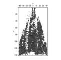
- FIG. 1 shows an approximately conical sample prepared from a Cu—Ag alloy wire, which is one embodiment of the present invention, and a 140 nm distance from a first position (0 nm position) corresponding to the tip of the prepared sample.
- FIG. 4 is a diagram of the isoconcentration surface of the Ag phase with a concentration of 2.0 atomic %.
- FIG. 2 shows data obtained in the same manner as in FIG.
- FIG. 1 is a diagram of an isoconcentration surface of an Ag phase having an Ag atomic concentration of 3.5 atomic % when the lower portion of the tip portion up to 1 is measured from the upper surface side.
- FIG. 3 is a diagram when the extension direction and the number of each Ag phase are plotted and calculated from the result of the isoconcentration surface of the Ag phase shown in FIG.
- FIG. 4 is a graph showing the interval (and the average diameter) between adjacent Ag phases calculated from the result of the equiconcentration surface of the Ag phase shown in FIG. 2 .
- FIG. 5 is a photograph of a bright field image (BF) when observing the metal structure in a cross section perpendicular to the longitudinal direction of the Cu—Ag alloy wire using a scanning transmission electron microscope (STEM).
- BF bright field image
- a Cu—Ag alloy wire according to one embodiment of the present invention is a Cu—Ag alloy wire having a chemical composition containing 1.0 to 6.0% by mass of Ag, with the balance being Cu and unavoidable impurities.
- the Cu—Ag alloy wire has a plurality of Ag phases distributed linearly in a matrix substantially in the longitudinal direction of the Cu—Ag alloy wire, and the Cu—Ag alloy wire
- the average crystal grain size of the parent phase is in the range of 10 to 60 nm when measured in a cross section orthogonal to the longitudinal direction of the core.
- the Cu—Ag alloy wire of the present invention contains 1.0 to 6.0% by mass of Ag. Ag is therefore an essential additive component. Ag exists in a solid solution state in Cu, which is the mother phase (first phase), or in a crystallized state as an Ag layer, which becomes a second phase during casting of a Cu—Ag alloy wire, and is solid. It exerts the action of solution strengthening or dispersion strengthening.
- the Ag content is set to 1.0 to 6.0% by mass. Furthermore, in a wide range of applications, when more emphasis is placed on the balance of electrical conductivity, the Ag content is more preferably 1.0 to 4.5% by mass.
- the Cu—Ag alloy wire which is one embodiment of the present invention, contains at least one component selected from the group consisting of Sn, Mg, Zn, In, Ni, Co, Zr and Cr as an optional additive component. , each preferably contained in the range of 0.05 to 0.30% by mass. All of these optionally added components are present mainly in the form of a solid solution in Cu, which is the matrix phase, and are elements that exert the effect of solid solution strengthening or dispersion strengthening, as in the case of Ag. In addition, when it is contained together with the Ag phase, it exists as a second phase of a ternary system or higher such as a Cu--Ag--Zr system, and contributes to further solid-solution strengthening or dispersion strengthening.
- a ternary system or higher such as a Cu--Ag--Zr system
- the content of each individual component is described below.
- Sn (tin) content is 0.05% by mass or more, it contributes to the improvement of the strength of the copper alloy wire. do not have. Therefore, the Sn content is 0.05% by mass or more, preferably 0.07% by mass or more, more preferably 0.08% by mass or more, and particularly preferably 0.10% by mass or more.
- the Sn content is 0.30% by mass or less, more preferably 0.18% by mass or less, still more preferably 0.15% by mass or less, and particularly preferably 0.12% by mass or less.
- Mg manganesium
- the content of Mg is 0.05% by mass or more, it contributes to improving the strength of the copper alloy wire and has the effect of alleviating the brittleness of the copper alloy wire.
- the Mg content is 0.30% by mass or less, the electrical conductivity of the copper alloy wire and the manufacturability during casting are not greatly impaired. Therefore, the content of Mg is 0.05% by mass or more, preferably 0.07% by mass or more, more preferably 0.08% by mass or more, and particularly preferably 0.10% by mass or more.
- the Mg content is 0.30% by mass or less, preferably 0.18% by mass or less, more preferably 0.15% by mass or less, and particularly preferably 0.12% by mass or less.
- the Zn (zinc) content is 0.05% by mass or more, it contributes to the improvement of the strength of the copper alloy wire and has the effect of alleviating the brittleness of the copper alloy wire.
- the Zn content is 0.30% by mass or less, the electrical conductivity of the copper alloy wire is not greatly impaired. Therefore, the Zn content is 0.05% by mass or more, preferably 0.07% by mass or more, more preferably 0.08% by mass or more, and particularly preferably 0.10% by mass or more.
- the Zn content is 0.30% by mass or less, more preferably 0.25% by mass or less, even more preferably 0.20% by mass or less, and particularly preferably 0.15% by mass or less.
- the In content is preferably 0.05% by mass or more, preferably 0.07% by mass or more, more preferably 0.08% by mass or more, and particularly preferably 0.10% by mass or more.
- the In content is 0.30% by mass or less, preferably 0.18% by mass or less, more preferably 0.15% by mass or less, and particularly preferably 0.12% by mass or less.
- Ni (nickel) content is 0.05% by mass or more, there is an effect of contributing to the strength improvement of the copper alloy wire.
- the Ni content is 0.30% by mass or less, the electrical conductivity of the copper alloy wire is not greatly impaired. Therefore, the Ni content is 0.05% by mass or more, preferably 0.07% by mass or more, more preferably 0.08% by mass or more, and particularly preferably 0.10% by mass or more.
- the Ni content is 0.30% by mass or less, preferably 0.25% by mass or less, more preferably 0.20% by mass or less, and particularly preferably 0.15% by mass or less.
- Co (cobalt) content is 0.05% by mass or more, it contributes to the improvement of the strength of the copper alloy wire. do not have. Therefore, the Co content is 0.05% by mass or more, preferably 0.07% by mass or more, more preferably 0.08% by mass or more, and particularly preferably 0.10% by mass or more. On the other hand, the Co content is 0.30% by mass or less, preferably 0.18% by mass or less, more preferably 0.15% by mass or less, and particularly preferably 0.12% by mass or less.
- ⁇ Zr 0.05 to 0.30% by mass>
- the content of Zr zirconium
- Zr zirconium
- the Zr content is 0.05% by mass or more, preferably 0.07% by mass or more, more preferably 0.08% by mass or more, and particularly preferably 0.10% by mass or more.
- the Zr content is 0.30% by mass or less, preferably 0.20% by mass or less, more preferably 0.15% by mass or less, and particularly preferably 0.12% by mass or less.
- the Cr (chromium) content is 0.05% by mass or more, it contributes to improving the strength of the copper alloy wire. do not have. Therefore, the Cr content is 0.05% by mass or more, preferably 0.07% by mass or more, more preferably 0.08% by mass or more, and particularly preferably 0.10% by mass or more. On the other hand, the Cr content is 0.30% by mass or less, preferably 0.18% by mass or less, more preferably 0.15% by mass or less, and particularly preferably 0.12% by mass or less.
- the optional additive components are preferably contained in a total amount of 0.05 to 1.0% by mass. If the content is less than 0.05% by mass, the decrease in electrical conductivity is small, but it does not contribute to high tensile strength. On the other hand, if the content exceeds 1.0% by mass, the tensile strength is significantly increased, but the electrical conductivity is greatly reduced, and high electrical conductivity cannot be maintained. Therefore, it is preferable that the total content of the optional additive components is in the range of 0.05 to 1.0% by mass. More preferably, the content is in the range of 0.1 to 0.5% by mass.
- Cu and inevitable impurities The balance other than the above components is Cu and unavoidable impurities.
- Cu is the parent phase of the Cu—Ag alloy wire of the present invention, and Ag and the like, which are essential additive components, are present in a solid solution state or in a precipitated state.
- the unavoidable impurity is an impurity of a content level that can be unavoidably included in the manufacturing process of the Cu—Ag alloy wire of the present invention. Inevitable impurities may cause a decrease in conductivity depending on the content. Therefore, considering the decrease in conductivity, it is preferable to suppress the content of unavoidable impurities. Examples of unavoidable impurities include Pb, S, P, and the like.
- a Cu—Ag alloy wire according to one embodiment of the present invention has a matrix in which a plurality of Ag phases are distributed in a line extending substantially in the longitudinal direction of the Cu—Ag alloy wire, and Cu -
- the average crystal grain size of the parent phase when measured in a cross section orthogonal to the longitudinal direction of the Ag-based alloy wire is in the range of 10 to 60 nm.
- a three-dimensional atom probe method 3DAP method
- 1 to 4 are diagrams showing the state of existence of Ag phases in the parent phase of a Cu—Ag alloy wire according to one embodiment of the present invention by the 3DAP method.
- the 3DAP method is an analysis technique that enables three-dimensional composition analysis of nanoprecipitates and clusters in metals and semiconductors. The principle is as follows. A needle-shaped sample with a diameter of about 100 nm is prepared with the tip formed in a substantially conical shape. Evaporate them one by one.
- a two-dimensional position detector detects the time-of-flight and position measurement of ions field-evaporated by pulse voltage and laser irradiation, and measures the two-dimensional coordinate position of each ion.
- Time-of-flight mass spectrometry analysis is also possible by measuring the time from the point of vaporization at the tip of the needle until the ion reaches the detector, so that the arriving ion species can be identified.
- information on the two-dimensional coordinate position of the ions and information on the depth direction of the sample can be obtained.
- three-dimensional composition information can be obtained. is possible.
- FIG. 1 shows a substantially conical sample prepared from a Cu—Ag alloy wire (Ag concentration: 2.0% by mass), which is one embodiment of the present invention, and corresponds to the tip of the prepared sample.
- FIG. 2 shows data obtained in the same manner as in FIG.
- FIG. 4 shows an isoconcentration surface of the Ag phase with an Ag atomic concentration of 3.5 atomic % when the lower portion of the tip portion up to 1 is measured from the upper surface side.
- FIG. 3 shows a graph obtained by figuring out the extending direction and the number of each Ag phase from the result of the isoconcentration surface of the Ag phase shown in FIG. 2 .
- FIG. 4 shows a graph obtained by figuring out the distance (and average diameter) between adjacent Ag phases from the result of the isoconcentration surface of the Ag phase shown in FIG.
- an Ag threshold with the same concentration as the Ag concentration is set, and the location where the concentration distribution exceeding this threshold can be confirmed is temporarily Ag phase and As shown in FIG. 1, it is possible to measure the longitudinal plane of the Ag phase having an atomic concentration exceeding a predetermined threshold value. Further, as shown in FIG. 2, it is possible to measure an image diagram of the Ag phase having an atomic concentration exceeding a predetermined threshold as viewed from the cross-sectional direction.
- the number of phases was counted by assigning Ag confirmed when 3.5 at% of the Ag equiconcentration surface in the cross section of the alloy wire was set as the threshold.
- FIG. 3 shows the result of assigning the Ag phase in the longitudinal direction of the line
- FIG. 4 shows the result of assigning the Ag phase in the cross section of the line. This is the result shown.
- the average diameter of the Ag phase was calculated from the area, assuming that the Ag phase is a perfect circle from the cross section perpendicular to the longitudinal direction of the selected Ag phase.
- This series of analyzes can be performed using IVAS, software for 3DAP equipment provided by CAMECA.
- FIG. 1 shows a substantially conical sample prepared from a Cu—Ag alloy wire (Ag concentration: 2.0% by mass), which is one embodiment of the present invention, and corresponds to the tip of the prepared sample.
- FIG. 2 shows data obtained in the same manner as in FIG.
- FIG. 4 shows an isoconcentration surface of the Ag phase with an Ag atomic concentration of 3.5 atomic % when the lower portion of the tip portion up to 1 is measured from the upper surface side.
- FIG. 3 shows a graph obtained by figuring out the extending direction and the number of each Ag phase from the result of the isoconcentration surface of the Ag phase shown in FIG. 2 .
- FIG. 4 shows a diagram when the average diameter of the Ag phase is plotted and calculated from the result of the isoconcentration surface of the Ag phase shown in FIG.
- the Cu--Ag alloy wire of the present invention has a matrix in which a plurality of Ag phases are linearly distributed in series in the substantially longitudinal direction of the Cu--Ag alloy wire.
- the Ag phases are not perfectly aligned in the longitudinal direction, but are substantially parallel and extend along the longitudinal direction of the wire.
- the Ag phase has an Ag atomic concentration of 0.5 to 50.0% and is continuous in the longitudinal direction.
- phase continuous in the longitudinal direction does not form a uniform phase with a constant Ag atomic concentration in the longitudinal direction, but the Ag atomic concentration is 0.5 to 50.0%.
- a phase is formed while fluctuating between
- the atomic concentration indicates the existence ratio of Ag, and if it is less than 0.5%, it is impossible to distinguish whether Ag is in a precipitated state or a solid solution state, and the second phase cannot be determined.
- the Ag phase if it exceeds 50.0%, the Ag phase becomes sufficiently coarse and the phase spacing tends to become sparse, so high tensile strength cannot be obtained. Therefore, the Ag phase must have an Ag atomic concentration in the range of 0.5 to 50.0 atomic %.
- the Ag phases are not continuous in the longitudinal direction, the intervals between the Ag phases become sparse, and the tensile strength and bending fatigue resistance cannot be improved. Therefore, the Ag phase forms a plurality of Ag phases distributed linearly in series in the substantially longitudinal direction of the Cu—Ag alloy wire.
- the Ag phase preferably has an average diameter in the range of 0.5 to 20 nm when measured in a cross section orthogonal to the longitudinal direction. If the average diameter of the Ag phase is less than 0.5 nm, the size is almost the same as the atomic diameter, and it is difficult to determine the solid solution or precipitation state of Ag with the resolution of existing analytical equipment. It is set as the lower limit because the relationship with the characteristics can be sufficiently clarified by specifying the A diameter larger than 20 nm has a low abundance ratio and a wide phase spacing, so it hardly contributes to densification. From this, since the improvement in tensile strength and bending fatigue resistance is at a negligible level, the presence of 20 nm or more need not be considered.
- the Cu—Ag alloy wire of the present invention is measured by a 3DAP device and analyzed by IVAS, and has an Ag atomic concentration in the range of 0.5 to 50.0 atomic% and an average diameter of 0.5 A phase in the range of ⁇ 20 nm is defined as an Ag phase.
- the crystal grain size of the Cu—Ag alloy wire is observed with a scanning transmission electron microscope (STEM).
- STEM is a device that irradiates an electron beam onto a sliced sample, captures electronic information transmitted through the sample, and performs high-magnification, high-resolution observation at a level that enables direct observation of atomic/molecular images. Therefore, STEM can image the atomic image distribution, morphology, composition image, crystal structure, etc. inside the sample by irradiating the sample with an electron beam focused to the minimum. In addition, STEM can capture the structure of substances in atomic images and sub-nm order.
- a focused ion beam (FIB) method was used to prepare a sample to be observed by STEM.
- SIINT-3050TB was used, and the acceleration voltage of the Ga ion beam was 30 kV.
- 2 kV Ar ion milling was performed for 5 minutes after FIB thin film processing.
- a JEOL ARM having an aberration correction function was used for STEM observation. Observations were made at an electron beam acceleration voltage of 200 kV.
- a bright field (BF: Bright Field) and a high-angle scattering dark field (HAADF: High-angle Annular Dark Field) were photographed.
- Energy dispersive X-ray spectroscopy (EDX) attached to STEM was used for elemental analysis.
- the cutting method JIS H 0501 was used from the obtained bright field image (BF) of the line cross section.
- the number of crystal grains completely cut by a line segment of known length was counted regardless of the direction on the image, and the average value (nm) of the cut length was taken.
- FIG. 5 is a photograph of a bright field image (BF) showing the metal structure in a cross section perpendicular to the longitudinal direction of the Cu—Ag alloy wire observed by STEM.
- the scale shown in FIG. 5 is 20 nm.
- the average crystal grain size of the parent phase when measured in a cross section perpendicular to the longitudinal direction is in the range of 10 to 60 nm. Recognize.
- the average crystal grain size of the parent phase is generally on the order of submicrons (0.1 ⁇ m or more) and at least larger than 60 nm.
- the Cu—Ag based copper alloy wire of the present invention has an average crystal grain size in the range of 10 to 60 nm.
- the parent phase is mainly composed of Cu and Ag dissolved therein. If the average crystal grain size observed from the cross section is less than 10 nm, the effect on the properties is unknown, but it was not confirmed within the scope of the present invention. When the average crystal grain size is within the range, the grain boundaries play a role of suppressing movement of dislocations and accumulating them, and can contribute to strength improvement (Hall-Petch rule).
- the tensile strength will eventually decrease.
- the average crystal grain size was quite coarse, but the Cu—Ag-based copper alloy wire of the present invention is controlled within the range of 10 to 60 nm. Achieves tensile strength and bending fatigue resistance. Specifically, when the crystal grain size is large, the amount of deformation carried by one crystal grain size is large, so the shear deformation within the crystal grain progresses and the shear band develops strongly. A large amount of precipitates causes stress concentration on brittle grain boundaries, creating a situation in which cracks are likely to occur at the grain boundaries.
- the Cu—Ag alloy wire of the present invention is a numerical value of the product of the average diameter (nm) of the Ag phase measured in the cross section and the average crystal grain size (nm) of the matrix phase (hereinafter simply “ (sometimes referred to as "value of the product”) is preferably smaller than 60 times the Ag content (% by mass) in the Cu—Ag alloy wire. If the numerical value of the product is smaller than 60 times the Ag content (% by mass) in the Cu—Ag alloy wire, the average diameter of the Ag phase and the average crystal grain size of the matrix phase are each fine. , sufficient strength characteristics and resistance to bending fatigue, especially when the average crystal grain size of the matrix is in the range of 10 to 60 nm, resistance to bending fatigue is further improved.
- the numerical value of the product is 60 times or more the Ag content (% by mass) in the Cu—Ag alloy wire, the Ag phase is very coarse with respect to the grain size of the parent phase, Tensile strength tends to decrease. Therefore, in the Cu--Ag alloy wire of the present invention, the value of the product is smaller than 60 times the Ag content (% by mass) in the Cu--Ag alloy wire.
- both numerical values of the average diameter (nm) of the Ag phase and the average crystal grain size (nm) of the matrix phase measured in the cross section are controlled so as to be small in a well-balanced manner. can be done.
- Cu—Ag alloy wires tend to have a finer wire diameter, and ultrafine wires are often used. Therefore, high tensile strength and high bending fatigue resistance are required.
- the Cu—Ag alloy wire of the present invention can obtain a tensile strength of at least 900 MPa or more, more preferably 1000 MPa or more, by forming the metal structure described above. Therefore, a Cu--Ag alloy wire having a high strength can be obtained even if the wire diameter is reduced.
- the use of ultra-fine wires requires high electrical conductivity.
- the Cu—Ag alloy wire of the present invention can obtain a conductivity of at least 65% IACS, more preferably 75% IACS or more, by suppressing the amount of additive elements and optional additive elements.
- the Cu—Ag alloy wire of the present invention is a round wire having a wire diameter of 0.01 mm to 0.08 mm and a substantially circular cross section. Even an ultra-thin wire (Cu—Ag alloy wire) having a wire diameter of 0.01 mm to 0.08 mm preferably has high tensile strength and high electrical conductivity. A Cu—Ag alloy wire with a wire diameter of less than 0.01 mm cannot be said to meet the needs of users. On the other hand, a Cu—Ag alloy wire with a wire diameter exceeding 0.08 mm cannot serve as an extra fine wire. Further, the Cu—Ag alloy wire may be a ribbon wire having a ribbon shape whose cross section is not substantially circular but substantially rectangular.
- the dimensions of the ribbon are preferably 0.02 to 0.32 mm in width and 0.002 to 0.040 mm in thickness for the same reasons as the upper and lower limits of the wire diameter.
- a manufacturing method for example, there is a method of rolling the drawn round wire into a desired shape.
- the strip width corresponds to the width direction of the rolling rolls, and the strip thickness corresponds to the direction between the rolls. At the ends in the strip width direction, the non-contacting roll roll portions are deformed while maintaining the shape of an arc.
- the longer value in the cross section of the ribbon wire is the width, and the shorter value is the thickness.
- the method for producing a Cu—Ag alloy wire of the present invention includes a casting step of melting and casting a Cu—Ag alloy material having the chemical composition described above and cooling it to obtain an ingot, and A first wire drawing step of drawing a Cu—Ag alloy material, a first heat treatment step of heat-treating the drawn Cu—Ag alloy material, a second heat treatment step, and finally, and a second wire drawing step for obtaining a Cu—Ag alloy wire by performing a wire drawing process.
- the strain relief annealing treatment can be performed between the wire drawing treatments of the second wire drawing process.
- the cooling rate is set to 10° C./second or more in order to suppress excessive appearance of Ag crystal precipitates in the Cu matrix during cooling during casting. If the crystal precipitates during casting become large, the space between the Ag phases becomes large without forming an Ag phase with an appropriate diameter even by drawing in the subsequent wire drawing process, so the final Cu—Ag alloy wire It causes a decrease in tensile strength.
- the working rate is preferably about 50 to 90% in order to promote sufficient precipitation of Ag during heat treatment. If the work ratio is less than 50%, sufficient precipitation is not generated, and the increase in strength with respect to the work ratio in the second wire drawing step and later steps becomes small. This is because the Cu—Ag alloy wire tends to have insufficient strength when the diameter is large, making it difficult to obtain high tensile strength. On the other hand, although precipitation is promoted in a wire drawing process with a working ratio of 90% or more, it is difficult to obtain a high tensile strength because the working ratio in the wire drawing process after the heat treatment cannot be high. , preferably set an upper limit of 90%.
- the first heat treatment step introduces at least two heat treatment steps while drawing the ingot to the final diameter.
- the purpose of this heat treatment is to precipitate Ag, and the holding temperature in the first heat treatment step is in the range of 350 to 450°C, and the holding temperature in the second heat treatment step is 250 to 375°C, for a total of 10 to 50 hours. within the range of The second heat treatment step needs to be performed at a low temperature of 25° C. or higher with respect to the first heat treatment step.
- the second heat treatment process By introducing the second heat treatment process at a temperature lower than that of the first heat treatment process, a large amount of precipitation of the Ag phase is precipitated by the first heat treatment with a large driving force, the solid solubility limit is narrowed, and the temperature is low. Therefore, the final precipitation amount of the Ag phase is controlled in the second heat treatment step in which the driving force is low. If the heat treatment temperature is low or the treatment time is short, recrystallization does not proceed at this point and the growth of the Ag phase does not occur. Moreover, the numerical value of the product of the average diameter of the Ag phase and the average crystal grain size of the matrix tends to be the numerical value of Ag concentration ⁇ 60 or more.
- the working rate of the second wire drawing step is desirably about 95% to 99.9999% in order to sufficiently develop the strength characteristics of the present alloy. If the processing rate is low, both the crystal grain size of the matrix phase and the Ag phase will not satisfy the quantity within the size range of the invention, and the tensile strength will not be increased sufficiently.
- the upper limit of the processing rate is a practical limitation and is not related to the characteristics.
- the working rate per pass is set in the range of 15 to 35%. A reduction greater than this may cause the wire to break.
- the ribbon-shaped wire was produced by rolling the above circular wire to the specified thickness.
- the work hardening may be saturated and the strength may be lowered. Saturation of work hardening may adversely affect the resistance to bending fatigue associated with twisting, so it is effective to apply an intermediate heat treatment for the purpose of strain relief without large softening.
- the final Cu--Ag alloy wire can be obtained by the finishing heat treatment step in which heat treatment is performed at the end of the manufacturing process (product after heat treatment).
- the conditions of this final heat treatment are not particularly limited, but it is preferable that the temperature is 450 to 600° C. and the time is 10 seconds to 30 minutes.
- this ingot was drawn to a wire diameter of 1.0 to 9.5 mm ⁇ so that the processing rate was 35 to 95% (first wire drawing step).
- aging heat treatment for both precipitation and recrystallization was performed at 350 to 550° C. for 3 to 50 hours (first heat treatment step).
- the holding temperature was held at a lower temperature, similarly, at 250 to 375° C. for 1 to 60 hours (second heat treatment step).
- cold wire drawing was performed to a wire diameter of 99.7 to 99.998% and 0.02 to 0.08 mm ⁇ (second wire drawing step).
- stress relief annealing was performed during the cold wire drawing in the second wire drawing process.
- Conductivity is measured using the four-probe method based on JIS H0505-1975 in a constant temperature bath controlled at 20 ° C. ( ⁇ 1 ° C.), and the conductivity is measured for two of each test piece, and the average value. (%IACS) was used as the measured value. At this time, the distance between terminals was set to 100 mm.
- the 3DAP device evaporates the material, detects the evaporated atoms with a two-dimensional detector, and reconstructs the data to visualize the three-dimensional structure of the nanometer order.
- Sample preparation for three-dimensional atom probe measurement was performed by FIB.
- FIB For the FIB, SIINT-3050TB and Helios G4 (manufactured by FEI) were used.
- a Ga ion beam with an acceleration voltage of 30 kV was used to fabricate a conical sample with a circular bottom surface with a diameter of about 80 nm and a length of about 140 nm.
- the longitudinal direction of the Cu—Ag alloy wire was taken as the length direction of the sample, but the diameter direction of the cross section perpendicular to the longitudinal direction of the Cu—Ag alloy wire may be taken as the length direction.
- the final finish used a 5 kV ion beam to reduce the damaged layer as much as possible.
- the 3DAP device used was LEAP4000XSi (manufactured by AMETEK).
- the irradiated pulsed laser was vaporized using ultraviolet light with a wavelength of 355 nm. Also, the voltage applied to the sample was set to 1 to 5 kV.
- Analysis software such as IVAS 3.8.8 (manufactured by CAMECA) or IVAS LT was used to analyze the atomic concentration of the Ag phase and the shortest interval.
- Average diameter of Ag phase In the 3DAP method, in a cross section orthogonal to the longitudinal direction of the Cu—Ag alloy wire, an Ag threshold with the same concentration as the Ag concentration is set, and the location where the concentration distribution exceeding this threshold can be confirmed is temporarily Ag phase and Corresponding to the tentative Ag phase, profile analysis was performed along the longitudinal direction, and the Ag phase having a continuous Ag atomic concentration of 0.5 to 50.0% in a length of 60 nm was selected as the Ag phase. The average diameter of the Ag phase was calculated from the area by assuming that the Ag phase is a perfect circle from the cross section perpendicular to the longitudinal direction of the selected Ag phase.
- STEM observation an atomic resolution analytical electron microscope (ARM manufactured by JEOL Ltd.: JEM-ARM200F) with an aberration correction function was used. Observations were made at an electron beam acceleration voltage of 200 kV. STEM observations were performed in bright field (BF) and high-angle scattering dark field (HAADF), and elemental analysis was performed using TEM at locations where contrast that could be attributed to the Ag layer was confirmed. It was carried out by attached energy dispersive X-ray analysis (EDX: Energy Dispersive X-ray spectroscopy).
- EDX Energy Dispersive X-ray spectroscopy
- the average crystal grain size was calculated from the obtained bright-field image (BF) using the cutting method.
- the cutting method is based on JIS H0501.
- the analysis results of the 3DAP apparatus were also used to obtain the average value.
- a numerical value was calculated from the product of the average diameter of the Ag phase and the average crystal grain size of the matrix phase.
- Examples 1-1 to 1-12, Comparative Examples 1-1 to 1-11 use a Cu—Ag alloy wire having a chemical composition of Cu—1.5% by mass Ag, and a Cu— Using Ag-based alloy wires, samples were prepared by changing the working ratios in the first and second wire drawing steps and the manufacturing conditions in the first and second heat treatment steps.
- Table 1 shows the manufacturing conditions of Examples 1-1 to 1-12 and Comparative Examples 1-1 to 1-11.
- Example 1-10 a circular shape with a final diameter of 0.03 mm was processed and formed into a ribbon shape with a thickness of 0.008 mm and a width of 0.08 mm.
- the underlines shown in the table indicate that they are outside the scope of the present invention.
- Table 2 shows evaluation results of metal structures and properties of Examples 1-1 to 1-12 and Comparative Examples 1-1 to 1-11.
- the evaluation items are the average crystal grain size of the matrix phase, the average diameter of the Ag phase, the numerical value of the product as the metal structure, and the tensile strength and bending fatigue resistance as the mechanical properties. Also, the numerical value of 60 times the Ag content (% by mass) is "90".
- the average crystal grain size of the mother phase, the average diameter of the Ag phase, and the numerical value of the product are within the scope of the present invention. All of them have a high tensile strength of 1100 MPa or more.
- the product value exceeds 90, which is 60 times the Ag content (% by mass), so the bending fatigue resistance is "O". ing.
- the value of the product is within 90, which is 60 times the Ag content (% by mass). The fatigue property is "A”.
- Comparative Examples 1-1 to 1-11 all have tensile strengths of 980 MPa or more, which are lower than those of Examples 1-1 to 1-12.
- the bending fatigue resistance is also "x".
- Example 2-1 to 2-12 Comparative Examples 2-1 to 2-11
- samples were prepared using a Cu—Ag alloy wire having a chemical composition of Cu-2.0 mass % Ag. .
- Table 3 shows the manufacturing conditions of Examples 2-1 to 2-12 and Comparative Examples 2-1 to 2-11.
- Table 4 shows evaluation results of metal structures and properties of Examples 2-1 to 2-12 and Comparative Examples 2-1 to 2-11.
- the numerical value of 60 times the Ag content (% by mass) is 120.
- the average crystal grain size of the mother phase, the average diameter of the Ag phase, and the numerical value of the product are within the scope of the present invention. All of them have a high tensile strength of 1100 MPa or more.
- the product value exceeds 120, which is 60 times the Ag content (% by mass), so the bending fatigue resistance is " ⁇ ”.
- the product value is within 120, which is 60 times the Ag content (% by mass), so the bending fatigue resistance is "A”.
- the average grain size of the mother phase and the numerical value of the product are outside the scope of the present invention, and the tensile strength is all 1000 MPa or more, and Examples 2-1 to 2-12 is getting lower.
- the numerical value of the product is a value greater than 120, and the bending fatigue resistance is also "x".
- Example 3-1 to 3-12 Comparative Examples 3-1 to 3-11
- samples were prepared using a Cu—Ag alloy wire having a chemical composition of Cu-4.0 mass % Ag. .
- Table 5 shows the manufacturing conditions of Examples 3-1 to 3-12 and Comparative Examples 3-1 to 3-11.
- Table 6 shows evaluation results of metal structures and properties of Examples 3-1 to 3-12 and Comparative Examples 3-1 to 3-11.
- the average crystal grain size of the matrix phase, the average diameter of the Ag phase, and the product values are all within the scope of the present invention. All of them have a high tensile strength of 1300 MPa or more.
- the numerical value of the product exceeds the numerical value 240, which is 60 times the Ag content (mass%).
- the fatigue property is " ⁇ ”.
- the numerical value of the product is within 240, which is 60 times the Ag content (mass%), the bending fatigue resistance is " ⁇ ”.
- Example 4-1 to 4-12 Comparative Examples 4-1 to 4-11
- samples were prepared using a Cu—Ag alloy wire having a chemical composition of Cu-6.0 mass % Ag. .
- Table 7 shows the manufacturing conditions of Examples 4-1 to 4-12 and Comparative Examples 4-1 to 4-11.
- Table 8 shows evaluation results of metal structures and properties of Examples 4-1 to 4-12 and Comparative Examples 4-1 to 4-11.
- the average crystal grain size of the matrix phase, the average diameter of the Ag phase, and the product values are all within the scope of the present invention. All of them have a high tensile strength of 1300 MPa or more.
- the bending fatigue resistance is "O". ing.
- the numerical value of the product is within 360, which is 60 times the Ag content (% by mass), the bending fatigue resistance is " ⁇ ”.
- the average grain size of the mother phase and the numerical value of the product are outside the scope of the present invention, and the tensile strength is all 1000 MPa or more, and Examples 4-1 to 4-12 is getting lower.
- the numerical value of the product is a value greater than 360, and the bending fatigue resistance is also "x".
- Comparative Examples 5-1 to 5-4 are Cu—Ag alloy wires containing 1.0 to 6.0% by mass of Ag outside the range of the present invention, and Cu-0.5% by mass of Ag , Cu-0.8 mass % Ag, Cu-6.5 mass % Ag, and Cu-8.0 mass % Ag.
- Table 9 shows the manufacturing conditions of Comparative Examples 5-1 to 5-4.
- Table 10 shows evaluation results of metal structures and properties of Comparative Examples 5-1 to 5-4.
- Comparative Example 5-4 the tensile strength was greater than 900 MPa because the upper limit of the amount of Ag added was greater than 6.0% by mass.
- the numerical value of the product is within 480, which is 60 times the Ag content (% by mass)
- the bending fatigue resistance is "A".
- Comparative Example 5-3 and Example 4-3, and Comparative Example 5-4 and Example 4-4 are compared, there is no difference in the effects of tensile strength and bending fatigue resistance, and the amount of Ag added is Even if it is increased, the cost only increases, and there is no advantage in increasing it.
- Examples 6-1 to 6-8 are Cu-2.0 wt% Ag and Cu having a chemical composition containing one selected from Sn, Mg, Zn, In, Ni, Co, Zr and Cr -Ag alloy wires
- Comparative Examples 6-1 to 6-3 are Cu-Ag having chemical compositions containing Cu-2.0% by mass Ag and 0.5% by mass of Sn, Mg, and Zr, respectively
- a sample is prepared using a series alloy wire.
- Table 11 shows the manufacturing conditions of Examples 6-1 to 6-8 and Comparative Examples 6-1 to 6-3.
- Table 12 shows evaluation results of metal structures and properties of Examples 6-1 to 6-8 and Comparative Examples 6-1 to 6-3.
- the average crystal grain size of the matrix phase, the average diameter of the Ag phase, and the product values are all within the scope of the present invention. All of them have a high tensile strength of 1100 MPa or more. Further, in Examples 6-1 to 6-8, the product value is within 120, which is 60 times the Ag content (% by mass), and therefore the bending fatigue resistance is "A".
- Comparative Example 6-1 containing 0.5% by mass of Sn and in Comparative Example 6-2 containing 0.5% by mass of Mg, the electrical conductivity is low, which poses a practical problem.
- Comparative Example 6-3 the 0.5% by mass Zr content causes ingot cracks during production, making it difficult to produce round wires and the like, which is problematic in terms of production.
Landscapes
- Chemical & Material Sciences (AREA)
- Engineering & Computer Science (AREA)
- Materials Engineering (AREA)
- Mechanical Engineering (AREA)
- Metallurgy (AREA)
- Organic Chemistry (AREA)
- Physics & Mathematics (AREA)
- Thermal Sciences (AREA)
- Crystallography & Structural Chemistry (AREA)
- Conductive Materials (AREA)
Priority Applications (4)
| Application Number | Priority Date | Filing Date | Title |
|---|---|---|---|
| EP22892803.2A EP4431624A4 (en) | 2021-11-12 | 2022-11-09 | CU-AG ALLOY WIRE |
| KR1020237022255A KR102915755B1 (ko) | 2021-11-12 | 2022-11-09 | Cu-Ag계 합금선 |
| CN202280008450.8A CN116670315A (zh) | 2021-11-12 | 2022-11-09 | Cu-Ag系合金线 |
| JP2023559663A JPWO2023085305A1 (https=) | 2021-11-12 | 2022-11-09 |
Applications Claiming Priority (2)
| Application Number | Priority Date | Filing Date | Title |
|---|---|---|---|
| JP2021-184764 | 2021-11-12 | ||
| JP2021184764 | 2021-11-12 |
Publications (1)
| Publication Number | Publication Date |
|---|---|
| WO2023085305A1 true WO2023085305A1 (ja) | 2023-05-19 |
Family
ID=86335742
Family Applications (1)
| Application Number | Title | Priority Date | Filing Date |
|---|---|---|---|
| PCT/JP2022/041680 Ceased WO2023085305A1 (ja) | 2021-11-12 | 2022-11-09 | Cu-Ag系合金線 |
Country Status (5)
| Country | Link |
|---|---|
| EP (1) | EP4431624A4 (https=) |
| JP (1) | JPWO2023085305A1 (https=) |
| KR (1) | KR102915755B1 (https=) |
| CN (1) | CN116670315A (https=) |
| WO (1) | WO2023085305A1 (https=) |
Cited By (1)
| Publication number | Priority date | Publication date | Assignee | Title |
|---|---|---|---|---|
| WO2024219028A1 (ja) * | 2023-04-21 | 2024-10-24 | 株式会社徳力本店 | Cu-Ag-Sn合金線材及びその製造方法、Cu-Ag-Sn合金線材を用いて得られた電気・電子部品検査用プローブピン |
Citations (6)
| Publication number | Priority date | Publication date | Assignee | Title |
|---|---|---|---|---|
| JP3325639B2 (ja) | 1993-03-31 | 2002-09-17 | 株式会社フジクラ | 高強度高導電率銅合金の製造方法 |
| JP2005336510A (ja) * | 2004-05-24 | 2005-12-08 | Hitachi Cable Ltd | 極細銅合金線及びその製造方法 |
| WO2011136284A1 (ja) * | 2010-04-28 | 2011-11-03 | 住友電気工業株式会社 | Cu-Ag合金線及びCu-Ag合金線の製造方法 |
| JP5051647B2 (ja) | 2005-10-17 | 2012-10-17 | 独立行政法人物質・材料研究機構 | 高強度・高導電率Cu−Ag合金細線とその製造方法 |
| WO2015152166A1 (ja) * | 2014-03-31 | 2015-10-08 | 古河電気工業株式会社 | 銅合金線材及びその製造方法 |
| WO2018100916A1 (ja) * | 2016-12-01 | 2018-06-07 | 古河電気工業株式会社 | 銅合金線材 |
Family Cites Families (6)
| Publication number | Priority date | Publication date | Assignee | Title |
|---|---|---|---|---|
| JP2006299287A (ja) * | 2005-04-15 | 2006-11-02 | Nikko Kinzoku Kk | 複相銅合金、ばね材及び箔体、並びに複相銅合金の製造方法 |
| JP2008081834A (ja) * | 2006-09-29 | 2008-04-10 | Nikko Kinzoku Kk | 高強度高導電性二相銅合金 |
| JP2011146352A (ja) * | 2010-01-18 | 2011-07-28 | Sumitomo Electric Ind Ltd | Cu−Ag合金線 |
| EP3550044B1 (en) * | 2016-12-02 | 2021-03-24 | Furukawa Electric Co., Ltd. | Copper alloy wire rod and method for producing copper alloy wire rod |
| JP7608049B2 (ja) * | 2018-03-20 | 2025-01-06 | 古河電気工業株式会社 | 銅合金線材及び銅合金線材の製造方法 |
| JP7547056B2 (ja) * | 2020-03-04 | 2024-09-09 | 古河電気工業株式会社 | 銅合金材およびその製造方法 |
-
2022
- 2022-11-09 WO PCT/JP2022/041680 patent/WO2023085305A1/ja not_active Ceased
- 2022-11-09 JP JP2023559663A patent/JPWO2023085305A1/ja active Pending
- 2022-11-09 KR KR1020237022255A patent/KR102915755B1/ko active Active
- 2022-11-09 CN CN202280008450.8A patent/CN116670315A/zh active Pending
- 2022-11-09 EP EP22892803.2A patent/EP4431624A4/en active Pending
Patent Citations (7)
| Publication number | Priority date | Publication date | Assignee | Title |
|---|---|---|---|---|
| JP3325639B2 (ja) | 1993-03-31 | 2002-09-17 | 株式会社フジクラ | 高強度高導電率銅合金の製造方法 |
| JP2005336510A (ja) * | 2004-05-24 | 2005-12-08 | Hitachi Cable Ltd | 極細銅合金線及びその製造方法 |
| JP5051647B2 (ja) | 2005-10-17 | 2012-10-17 | 独立行政法人物質・材料研究機構 | 高強度・高導電率Cu−Ag合金細線とその製造方法 |
| WO2011136284A1 (ja) * | 2010-04-28 | 2011-11-03 | 住友電気工業株式会社 | Cu-Ag合金線及びCu-Ag合金線の製造方法 |
| JP5713230B2 (ja) | 2010-04-28 | 2015-05-07 | 住友電気工業株式会社 | Cu−Ag合金線及びCu−Ag合金線の製造方法 |
| WO2015152166A1 (ja) * | 2014-03-31 | 2015-10-08 | 古河電気工業株式会社 | 銅合金線材及びその製造方法 |
| WO2018100916A1 (ja) * | 2016-12-01 | 2018-06-07 | 古河電気工業株式会社 | 銅合金線材 |
Non-Patent Citations (1)
| Title |
|---|
| See also references of EP4431624A4 |
Cited By (1)
| Publication number | Priority date | Publication date | Assignee | Title |
|---|---|---|---|---|
| WO2024219028A1 (ja) * | 2023-04-21 | 2024-10-24 | 株式会社徳力本店 | Cu-Ag-Sn合金線材及びその製造方法、Cu-Ag-Sn合金線材を用いて得られた電気・電子部品検査用プローブピン |
Also Published As
| Publication number | Publication date |
|---|---|
| CN116670315A (zh) | 2023-08-29 |
| KR20230138448A (ko) | 2023-10-05 |
| KR102915755B1 (ko) | 2026-01-20 |
| EP4431624A1 (en) | 2024-09-18 |
| EP4431624A4 (en) | 2026-02-18 |
| JPWO2023085305A1 (https=) | 2023-05-19 |
Similar Documents
| Publication | Publication Date | Title |
|---|---|---|
| JP5170916B2 (ja) | 銅合金板材及びその製造方法 | |
| US10844468B2 (en) | Copper alloy sheet material and current-carrying component | |
| KR102590058B1 (ko) | 구리 합금 판재 및 그 제조 방법 | |
| WO2009123136A1 (ja) | 電子材料用Cu-Ni-Si系合金 | |
| JPWO2010126046A1 (ja) | 導電性と曲げ性を改善したCu−Ni−Si−Mg系合金 | |
| KR20120130342A (ko) | 전자 재료용 Cu-Ni-Si 계 합금 | |
| KR20030057561A (ko) | 굽힘가공성이 우수한 고강도 동합금과 그 제조방법 및그것을 사용한 단자ㆍ커넥터 | |
| US20110038753A1 (en) | Copper alloy sheet material | |
| KR102915759B1 (ko) | Cu-Ag계 합금선 | |
| JP5468798B2 (ja) | 銅合金板材 | |
| WO2023085305A1 (ja) | Cu-Ag系合金線 | |
| EP2944703A1 (en) | Copper alloy for electronic or electrical device, copper alloy thin sheet for electronic or electrical device, process for manufacturing copper alloy for electronic or electrical device, conductive component for electronic or electrical device, and terminal | |
| JP4006468B1 (ja) | 高強度、高導電率および曲げ加工性に優れた銅合金 | |
| JP2008075151A (ja) | 高強度、高導電率および曲げ加工性に優れた銅合金 | |
| TWI639163B (zh) | Cu-Co-Ni-Si alloy for electronic parts, and electronic parts | |
| JP2008088558A (ja) | 延性に優れた高力高導電性銅合金 | |
| KR102862623B1 (ko) | 구리 합금 선재 | |
| CN115398014B (zh) | 铜合金线材 | |
| JP6762453B1 (ja) | 銅合金板材およびその製造方法 | |
| JP4349631B2 (ja) | 電機、電子機器部品用コルソン合金細線の製造方法 | |
| WO2023140314A1 (ja) | 銅合金板材およびその製造方法 | |
| KR20250003496A (ko) | Cu-Ag계 합금선 | |
| JP2016125094A (ja) | 電子・電気機器用銅合金、電子・電気機器用銅合金薄板、電子・電気機器用部品、及び、端子 |
Legal Events
| Date | Code | Title | Description |
|---|---|---|---|
| WWE | Wipo information: entry into national phase |
Ref document number: 2023559663 Country of ref document: JP |
|
| WWE | Wipo information: entry into national phase |
Ref document number: 202280008450.8 Country of ref document: CN |
|
| 121 | Ep: the epo has been informed by wipo that ep was designated in this application |
Ref document number: 22892803 Country of ref document: EP Kind code of ref document: A1 |
|
| WWE | Wipo information: entry into national phase |
Ref document number: 2022892803 Country of ref document: EP |
|
| NENP | Non-entry into the national phase |
Ref country code: DE |
|
| ENP | Entry into the national phase |
Ref document number: 2022892803 Country of ref document: EP Effective date: 20240612 |