WO2023085134A1 - 光ファイバ - Google Patents
光ファイバ Download PDFInfo
- Publication number
- WO2023085134A1 WO2023085134A1 PCT/JP2022/040547 JP2022040547W WO2023085134A1 WO 2023085134 A1 WO2023085134 A1 WO 2023085134A1 JP 2022040547 W JP2022040547 W JP 2022040547W WO 2023085134 A1 WO2023085134 A1 WO 2023085134A1
- Authority
- WO
- WIPO (PCT)
- Prior art keywords
- refractive index
- optical fiber
- less
- fiber according
- layer
- Prior art date
- Legal status (The legal status is an assumption and is not a legal conclusion. Google has not performed a legal analysis and makes no representation as to the accuracy of the status listed.)
- Ceased
Links
Images
Classifications
-
- G—PHYSICS
- G02—OPTICS
- G02B—OPTICAL ELEMENTS, SYSTEMS OR APPARATUS
- G02B6/00—Light guides; Structural details of arrangements comprising light guides and other optical elements, e.g. couplings
- G02B6/02—Optical fibres with cladding with or without a coating
- G02B6/036—Optical fibres with cladding with or without a coating core or cladding comprising multiple layers
- G02B6/03694—Multiple layers differing in properties other than the refractive index, e.g. attenuation, diffusion, stress properties
-
- G—PHYSICS
- G02—OPTICS
- G02B—OPTICAL ELEMENTS, SYSTEMS OR APPARATUS
- G02B6/00—Light guides; Structural details of arrangements comprising light guides and other optical elements, e.g. couplings
- G02B6/02—Optical fibres with cladding with or without a coating
- G02B6/036—Optical fibres with cladding with or without a coating core or cladding comprising multiple layers
- G02B6/03616—Optical fibres characterised both by the number of different refractive index layers around the central core segment, i.e. around the innermost high index core layer, and their relative refractive index difference
- G02B6/03638—Optical fibres characterised both by the number of different refractive index layers around the central core segment, i.e. around the innermost high index core layer, and their relative refractive index difference having 3 layers only
- G02B6/0365—Optical fibres characterised both by the number of different refractive index layers around the central core segment, i.e. around the innermost high index core layer, and their relative refractive index difference having 3 layers only arranged - - +
-
- C—CHEMISTRY; METALLURGY
- C03—GLASS; MINERAL OR SLAG WOOL
- C03B—MANUFACTURE, SHAPING, OR SUPPLEMENTARY PROCESSES
- C03B37/00—Manufacture or treatment of flakes, fibres, or filaments from softened glass, minerals, or slags
- C03B37/01—Manufacture of glass fibres or filaments
- C03B37/02—Manufacture of glass fibres or filaments by drawing or extruding, e.g. direct drawing of molten glass from nozzles; Cooling fins therefor
- C03B37/025—Manufacture of glass fibres or filaments by drawing or extruding, e.g. direct drawing of molten glass from nozzles; Cooling fins therefor from reheated softened tubes, rods, fibres or filaments, e.g. drawing fibres from preforms
- C03B37/027—Fibres composed of different sorts of glass, e.g. glass optical fibres
-
- C—CHEMISTRY; METALLURGY
- C03—GLASS; MINERAL OR SLAG WOOL
- C03C—CHEMICAL COMPOSITION OF GLASSES, GLAZES OR VITREOUS ENAMELS; SURFACE TREATMENT OF GLASS; SURFACE TREATMENT OF FIBRES OR FILAMENTS MADE FROM GLASS, MINERALS OR SLAGS; JOINING GLASS TO GLASS OR OTHER MATERIALS
- C03C25/00—Surface treatment of fibres or filaments made from glass, minerals or slags
- C03C25/10—Coating
- C03C25/104—Coating to obtain optical fibres
- C03C25/1065—Multiple coatings
-
- G—PHYSICS
- G02—OPTICS
- G02B—OPTICAL ELEMENTS, SYSTEMS OR APPARATUS
- G02B6/00—Light guides; Structural details of arrangements comprising light guides and other optical elements, e.g. couplings
- G02B6/02—Optical fibres with cladding with or without a coating
- G02B6/028—Optical fibres with cladding with or without a coating with core or cladding having graded refractive index
-
- G—PHYSICS
- G02—OPTICS
- G02B—OPTICAL ELEMENTS, SYSTEMS OR APPARATUS
- G02B6/00—Light guides; Structural details of arrangements comprising light guides and other optical elements, e.g. couplings
- G02B6/02—Optical fibres with cladding with or without a coating
- G02B6/036—Optical fibres with cladding with or without a coating core or cladding comprising multiple layers
- G02B6/03616—Optical fibres characterised both by the number of different refractive index layers around the central core segment, i.e. around the innermost high index core layer, and their relative refractive index difference
- G02B6/03622—Optical fibres characterised both by the number of different refractive index layers around the central core segment, i.e. around the innermost high index core layer, and their relative refractive index difference having 2 layers only
- G02B6/03627—Optical fibres characterised both by the number of different refractive index layers around the central core segment, i.e. around the innermost high index core layer, and their relative refractive index difference having 2 layers only arranged - +
Definitions
- the present invention relates to optical fibers.
- Efforts to achieve low bending loss mainly include control of the refractive index profile.
- the refractive index profile For example, in the case of a trench profile, it is possible to easily reduce the bending loss by providing a trench layer in the cladding region, and also to achieve good characteristics for other characteristics such as the MFD (mode field diameter). is possible.
- optical fibers with residual stress have been disclosed in order to improve properties such as breaking properties in optical fibers (Patent Documents 1 to 5).
- JP 2007-297254 A Japanese Patent No. 4663277 Japanese Patent Application Laid-Open No. 2003-207675 Japanese Patent No. 5831189 Japanese Patent No. 6020045
- the main means of refractive index profile control technology was dopant control.
- the refractive index of the core portion is decreased or the amount of dopant in the core portion is increased to increase the relative refractive index difference between the core portion and the clad portion.
- means were employed.
- there are concerns such as deterioration of transmission loss due to an increase in Rayleigh scattering accompanying the addition of dopants and the establishment of dopant addition technology.
- the present invention has been made in view of the above, and its object is to provide an optical fiber with low bending loss while suppressing an increase in transmission loss.
- one aspect of the present invention provides a core portion, a cladding portion having a lower refractive index than the maximum refractive index of the core portion and surrounding the outer periphery of the core portion,
- the core portion includes a germanium-doped center core, and a low refractive index layer in which - ⁇ max, which is the minimum value of the relative refractive index difference to the average refractive index of the clad portion, is negative, surrounding the outer periphery of the center core.
- the residual compressive stress in the center core is 40 MPa or more and 150 MPa or less, and ⁇ 1, which is the average maximum relative refractive index difference of the center core with respect to the average refractive index of the cladding portion, is 0.8% or less. Fiber.
- the - ⁇ max may be -0.5% or more and -0.1% or less.
- the low refractive index layer may be a trench layer separated from the center core.
- the diameter of the center core may be 3 ⁇ m or more and 8 ⁇ m or less, and the outer diameter of the trench layer may be 9 ⁇ m or more and 20 ⁇ m or less.
- the diameter of the center core may be 3.5 ⁇ m or more and 7.5 ⁇ m or less, and the outer diameter of the trench layer may be 9.5 ⁇ m or more and 19 ⁇ m or less.
- the diameter of the center core may be 3.5 ⁇ m or more and 5 ⁇ m or less, and the outer diameter of the trench layer may be 12 ⁇ m or more and 16 ⁇ m or less.
- the low refractive index layer may be a depressed layer adjacent to the center core.
- the center core may have a diameter of 3 ⁇ m or more and 8 ⁇ m or less, and the depressed layer may have an outer diameter of 9 ⁇ m or more and 20 ⁇ m or less.
- the center core may have a diameter of 3.5 ⁇ m or more and 7.5 ⁇ m or less, and the depressed layer may have an outer diameter of 9.5 ⁇ m or more and 19 ⁇ m or less.
- the center core may have a diameter of 3.5 ⁇ m or more and 5 ⁇ m or less, and the depressed layer may have an outer diameter of 12 ⁇ m or more and 16 ⁇ m or less.
- the relative refractive index difference may continuously change from the center core to the low refractive index layer in the radial direction.
- the refractive index profile representing the relative refractive index difference changes smoothly without sharp bending, and the amount of change is 0.1% or less per 1 ⁇ m in the radial direction. It can mean something.
- the residual compressive stress in the low refractive index layer may be 20 MPa or more and 200 MPa or less.
- the low refractive index layer may contain fluorine.
- It may have a transmission loss of 0.190 dB/km or less at a wavelength of 1550 nm, a mode field diameter of 8.6 ⁇ m or more at a wavelength of 1310 nm, a cable cutoff wavelength of 1260 nm or less, and a zero dispersion wavelength of 1300 nm or more.
- the macrobending loss when wound with a diameter of 20 mm may be 0.1 dB/turn or less.
- the cladding diameter may be within the range of 125 ⁇ m ⁇ 10 ⁇ m.
- the cladding diameter may be within the range of 115 ⁇ m ⁇ 10 ⁇ m.
- the cladding diameter may be within the range of 105 ⁇ m ⁇ 10 ⁇ m.
- the cladding diameter may be within the range of 95 ⁇ m ⁇ 10 ⁇ m.
- the cladding diameter may be within the range of 85 ⁇ m ⁇ 10 ⁇ m.
- the secondary layer may be made of a resin having a Young's modulus of 5 MPa or more and 2000 MPa or less.
- the maximum residual stress difference between the core portion and the clad portion may be 40 MPa or more and 220 MPa or less.
- the maximum residual stress difference between the core portion and the clad portion may be 70 MPa or more and 220 MPa or less.
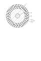
- FIG. 1 is a schematic cross-sectional view of a plane perpendicular to the longitudinal direction of an optical fiber according to Embodiment 1.
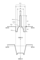
- FIG. FIG. 2 is a schematic diagram of a refractive index profile and corresponding residual stress of an optical fiber according to Embodiment 1;
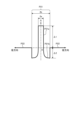
- FIG. 3 is a schematic diagram of a refractive index profile of an optical fiber according to Embodiment 2.
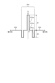
- FIG. 4 is a schematic diagram of a refractive index profile of an optical fiber according to a comparative example.
- the cutoff wavelength or the effective cutoff wavelength refers to the ITU-T G.I. Refers to the cable cutoff wavelength ( ⁇ cc) defined in R.650.1. For other terms not specifically defined in this specification, see G.I. 650.1 and G.I. 650.2 shall comply with the definition and measurement method.
- FIG. 1 is a schematic cross-sectional view of a plane perpendicular to the longitudinal direction of an optical fiber according to Embodiment 1.
- the optical fiber 1 is made of silica-based glass, and includes a core portion 1a and a clad portion 1b surrounding the outer periphery of the core portion 1a and having a lower refractive index than the maximum refractive index of the core portion 1a.
- a portion of the optical fiber 1 including the core portion 1a and the clad portion 1b is a portion made of glass in the optical fiber, and is sometimes referred to as a glass optical fiber.
- the optical fiber 1 also includes a coating portion 1c surrounding the outer circumference of the clad portion 1b.
- the coating portion 1c has a primary layer 1ca surrounding the outer periphery of the clad portion 1b and a secondary layer 1cb surrounding the outer periphery of the primary layer 1ca.
- An optical fiber provided with the coating portion 1c may be described as an optical fiber core wire.
- the outer diameter (cladding diameter) of the clad portion 1b is not particularly limited, it is preferably within the range of 125 ⁇ m ⁇ 10 ⁇ m.
- the cladding diameter may be within the range of 115 ⁇ m ⁇ 10 ⁇ m, 105 ⁇ m ⁇ 10 ⁇ m, or 95 ⁇ m ⁇ 10 ⁇ m from the viewpoint of reducing the diameter of the optical fiber 1. may be within the range of 85 ⁇ m ⁇ 10 ⁇ m.
- the outer diameter of the secondary layer 1cb is, for example, 260 ⁇ m or less, but it may be reduced in accordance with the reduction in clad diameter.
- the primary layer 1ca is made of a resin having a Young's modulus of 0.2 MPa or more and 3 MPa or less, for example.
- the secondary layer 1cb consists of resin whose Young's modulus is 5 MPa or more and 2000 MPa or less, for example.
- the resin forming the primary layer 1ca and the resin forming the secondary layer 1cb are, for example, UV curable resins.
- the UV curable resin is a mixture of various resin materials and additives such as oligomers, diluent monomers, photopolymerization initiators, silane coupling agents, sensitizers and lubricants.
- oligomer conventionally known materials such as polyether urethane acrylate, epoxy acrylate, polyester acrylate, and silicone acrylate can be used.
- Conventionally known materials such as monofunctional monomers and polyfunctional monomers can be used as the diluent monomer.
- the additives are not limited to those described above, and conventionally known additives and the like used for ultraviolet curable resins and the like can be widely used.
- FIG. 2 is a schematic diagram of the refractive index profile of the optical fiber according to Embodiment 1 and the corresponding residual stress.
- the refractive index profile shown in FIG. 2 is a so-called trench-type refractive index profile and represents a relative refractive index difference.
- profile P11 indicates the refractive index profile of the core portion 1a
- profile P12 indicates the refractive index profile of the clad portion 1b.
- the core portion 1a is formed so as to surround the center core having a diameter of 2a and the outer circumference of the center core, and has a refractive index smaller than the maximum refractive index of the center core, an inner diameter of 2a, and an outer diameter of 2a.
- Profile P11a is the refractive index profile of the center core
- profile P11b is the refractive index profile of the intermediate layer
- profile P11c is the refractive index profile of the trench layer.
- the center core is a portion having the highest average refractive index in the core portion 1a.
- the average maximum relative refractive index difference of the center core with respect to the average refractive index of the cladding portion 1b is ⁇ 1.
- the trench layer surrounds the outer periphery of the center core and has a negative minimum value of - ⁇ max, which is the relative refractive index difference with respect to the average refractive index of the cladding portion 1b, and is an example of a low refractive index layer.
- - ⁇ max is written as ⁇ 2.
- the trench layer is separated from the center core by an intermediate layer.
- the relative refractive index difference changes continuously from the inside to the outside in the radial direction.
- the relative refractive index difference changes continuously from the center core to the trench layer in the radial direction.
- the relative refractive index difference continuously changes means that the refractive index profile representing the relative refractive index difference changes smoothly without sharp bending, and the amount of change is 0.1% per 1 ⁇ m in the radial direction. means that:
- the boundary between the intermediate layer and the trench layer can be defined by the amount of change in the relative refractive index difference.
- the amount of change in the relative refractive index difference when viewed from the center side, if it is 0.1% or less per 1 ⁇ m in the radial direction, it is an intermediate layer, and if it exceeds 0.1%, it crosses the boundary. It can be said that it moved to the trench layer.
- the refractive index profile of the center core of the core portion 1a is not limited to a geometrically ideal stepped shape, but the shape of the top is not flat, and unevenness is formed due to manufacturing characteristics. It may have a shape that draws In this case, the refractive index of the substantially flat region at the top of the refractive index profile within the range of the core diameter 2a (diameter of the center core) of the core portion 1a in manufacturing design serves as an index for determining ⁇ 1.
- a substantially flat region seems to be divided into multiple places, or when a continuous change occurs and it is difficult to define a substantially flat region, it is also possible to sharply bend toward the next layer.
- At least any part of the core part other than the part where the rate changes is within the range of ⁇ 1 below, and the difference in ⁇ between the maximum value and the minimum value is within ⁇ 30% of a certain value, desired It has been confirmed that it is possible to produce characteristics close to , and there is no particular problem.
- a center core of the core portion 1a is made of quartz glass to which germanium (Ge) is added.
- Ge is a dopant that increases the refractive index of quartz glass.
- At least part of the trench layer is made of silica glass containing a dopant that lowers the refractive index, such as fluorine (F) or boron (B).
- the intermediate layer is made of silica glass having the same or similar composition as that of the cladding portion 1b.
- the cladding portion 1b is made of pure silica glass, for example.
- Pure silica glass is very pure silica glass that does not substantially contain dopants that change the refractive index and has a refractive index of about 1.444 at a wavelength of 1550 nm.
- a dopant may be added to the clad portion 1b.
- the core portion 1a has residual compressive stress, and particularly the residual compressive stress in the center core is 40 MPa or more and 150 MPa or less.
- the center core is subject to the photoelastic effect, and in addition to the refractive index increasing effect of dopants such as Ge that increase the refractive index, the photoelastic effect increases the refractive index. Therefore, the amount of dopant added for realizing the same ⁇ 1 can be reduced. As a result, the occurrence of Rayleigh scattering due to the dopant can be relatively reduced, so that the transmission loss can be reduced.
- ⁇ 1 can be increased by the photoelastic effect to realize low bending loss characteristics.
- the residual compressive stress in the center core is 40 MPa or more, the effect of increasing the refractive index due to the photoelastic effect is sufficient, and 150 MPa or less is practically preferable.
- the temperature during wire drawing, which will be described later, is low, and there is a possibility that the transmission loss will deteriorate due to the generation of glass structural defects.
- the cladding portion 1b has residual tensile stress.
- the difference in residual stress between the core portion 1a and the cladding portion 1b increases, so the difference in relative refractive index also increases, which is preferable for achieving low bending loss while suppressing an increase in transmission loss.
- the optical fiber 1 according to Embodiment 1 has characteristics of low bending loss while suppressing an increase in transmission loss.
- ⁇ 1 of the center core is 0.8% or less, it is preferable in that the dopant such as Ge can be reduced and an increase in transmission loss is suppressed. In addition, if ⁇ 1 of the center core is 0.8% or less, it is preferable from the viewpoint of suppressing the occurrence of foaming during manufacturing.
- ⁇ 1 of the center core is preferably larger than 0.25%. This is because if ⁇ 1 of the center core is 0.25% or less, the light confinement effect is weakened, and there is a possibility that the bending loss will deteriorate and the zero dispersion wavelength will shift to a shorter wavelength.
- - ⁇ max ( ⁇ 2) of the trench layer is -0.5% or more and -0.1% or less in order to realize low bending loss.
- the core diameter 2a (see FIG. 2), which is the diameter of the center core, is 3 ⁇ m or more and 8 ⁇ m or less, and the outer diameter 2c (see FIG. 2) of the trench layer is 9 ⁇ m or more and 20 ⁇ m or less.
- the core diameter 2a is 3.5 ⁇ m or more and 7.5 ⁇ m or more
- the outer diameter 2c of the trench layer is 9.5 ⁇ m or more and 19 ⁇ m or less.
- the core diameter 2a is 3.5 ⁇ m or more and 5 ⁇ m or less
- the trench layer outer diameter 2c is 12 ⁇ m or more and 16 ⁇ m or less.
- the core diameter 2a within the above range is preferable in that the characteristics of the optical fiber 1 such as low bending loss, mode field diameter, cutoff wavelength and zero dispersion wavelength can be obtained in a well-balanced manner.
- the transmission loss is 0.190 dB/km or less at a wavelength of 1550 nm
- the mode field diameter is 8.6 ⁇ m or more at a wavelength of 1310 nm
- the cable cutoff wavelength is 1260 nm or less
- the zero dispersion wavelength is 1300 nm or more.
- the good characteristics of the optical fiber 1 can be obtained in a well-balanced manner.
- control of the outer diameter 2c of the trench layer is effective in reducing bending loss.
- the maximum value of the residual stress difference between the core portion 1a and the clad portion 1b is 40 MPa or more and 220 MPa or less, it is preferable in terms of realizing low bending loss while suppressing an increase in transmission loss. It is more preferable if the value is 70 MPa or more.
- the trench layer is soft, so that the structural relaxation of the core portion 1a can reduce the transmission loss. Furthermore, since the entire core portion 1a can be made into a compressed atmosphere, an effect that the refractive index is likely to increase due to the photoelastic effect is obtained as a result.
- the optical fiber 1 having residual stress as shown in FIG. It can be realized by appropriately adjusting the line speed, tension and temperature.
- the optical fiber according to the second embodiment differs from the first embodiment in that the refractive index profile is a so-called W-shape. Therefore, the refractive index profile of the optical fiber according to the second embodiment will be described below, and other descriptions will be omitted as appropriate.
- FIG. 3 is a schematic diagram of a refractive index profile of an optical fiber according to Embodiment 2.
- FIG. The refractive index profile shown in FIG. 3 is a W-shaped refractive index profile and represents a relative refractive index difference.
- profile P21 indicates the refractive index profile of the core portion
- profile P22 indicates the refractive index profile of the clad portion.
- the core portion is formed so as to surround the center core having a diameter of 2a and the outer circumference of the center core, and has a smaller refractive index than the clad portion, and has an inner diameter of 2a and an outer diameter of 2b. It is composed of a depressed layer of Profile P21a is the refractive index profile of the center core, and profile P21b is the refractive index profile of the depressed layer.
- the center core is the portion with the highest average refractive index in the core portion.
- the average maximum relative refractive index difference of the center core with respect to the average refractive index of the cladding is ⁇ 1.
- the depressed layer surrounds the outer periphery of the center core and has a negative minimum value of ⁇ max in the relative refractive index difference with respect to the average refractive index of the cladding, and is an example of a low refractive index layer. In FIG. 3, - ⁇ max is written as ⁇ 2.
- the depressed layer is adjacent to the center core.
- the relative refractive index difference changes continuously from the inside to the outside in the radial direction.
- the relative refractive index difference changes continuously from the center core to the depressed layer in the radial direction.
- the relative refractive index difference continuously changes means that the refractive index profile representing the relative refractive index difference changes smoothly without sharp bending, and the amount of change is 0.1% per 1 ⁇ m in the radial direction.
- the core portion has residual compressive stress, and particularly the residual compressive stress in the center core is 40 MPa or more and 150 MPa or less.
- the amount of dopant to be added to achieve the same ⁇ 1 can be reduced as in the case of the first embodiment, so that the transmission loss can be reduced.
- ⁇ 1 can be increased by the photoelastic effect to realize low bending loss characteristics.
- the cladding portion has residual tensile stress.
- the optical fiber according to the second embodiment has characteristics of low bending loss while suppressing an increase in transmission loss.
- ⁇ 1 of the center core is preferably 0.8% or less in terms of suppressing an increase in transmission loss and suppressing the occurrence of foaming during manufacturing. Also, ⁇ 1 of the center core is preferably greater than 0.25%. This is because if ⁇ 1 of the center core is 0.25% or less, the light confinement effect is weakened, and there is a possibility that the bending loss will deteriorate and the zero dispersion wavelength will shift to a shorter wavelength.
- - ⁇ max ( ⁇ 2) of the depressed layer is -0.5% or more and -0.1% or less.
- the core diameter 2a (see FIG. 3), which is the diameter of the center core, is 3 ⁇ m or more and 8 ⁇ m or less, and the outer diameter 2b (see FIG. 3) of the depressed layer is 9 ⁇ m or more. It is preferably 20 ⁇ m or less. More preferably, the core diameter 2a is 3.5 ⁇ m or more and 7.5 ⁇ m or more, and the depressed layer outer diameter 2b is 9.5 ⁇ m or more and 19 ⁇ m or less. More preferably, the core diameter 2a is 3.5 ⁇ m or more and 5 ⁇ m or less, and the depressed layer outer diameter 2b is 12 ⁇ m or more and 16 ⁇ m or less.
- the core diameter 2a within the above range is preferable in that the characteristics of the optical fiber according to Embodiment 2, such as low bending loss, mode field diameter, cutoff wavelength and zero dispersion wavelength, can be obtained in a well-balanced manner.
- the transmission loss is 0.190 dB/km or less at a wavelength of 1550 nm
- the mode field diameter is 8.6 ⁇ m or more at a wavelength of 1310 nm
- the cable cutoff wavelength is 1260 nm or less
- the zero dispersion wavelength is 1300 nm or more.
- the excellent characteristics of the optical fiber according to the second embodiment can be obtained in a well-balanced manner.
- control of the outer diameter 2b of the depressed layer is effective in reducing bending loss.
- the maximum value of the residual stress difference between the core portion and the cladding portion is 40 MPa or more and 220 MPa or less, it is preferable for realizing low bending loss while suppressing an increase in transmission loss, and the maximum value of the difference is It is more preferable if it is 70 MPa or more.
- the residual compressive stress in the depressed layer is 20 MPa or more and 200 MPa or less, it is preferable in terms of realizing low bending loss.
- the optical fibers according to Embodiments 1 and 2 preferably have a low transmission loss if the transmission loss is 0.190 dB/km or less at a wavelength of 1550 nm.
- the mode field diameter is 8.6 ⁇ m or more at a wavelength of 1310 nm
- the cable cutoff wavelength is 1260 nm or less
- the zero dispersion wavelength is 1300 nm or more, ITU-T G652. It is preferable because it is an optical fiber that satisfies at least part of the D standard.
- the macrobend loss when wound with a diameter of 20 mm is 0.1 dB/turn or less, the bending loss is low, ITU-T G657. It is preferable because it is an optical fiber that satisfies at least part of the A2 standard.
- Example 1 As examples of the present invention, optical fibers of Examples 1 to 6 having refractive index profiles shown in FIG. 2 were manufactured. When producing the optical fibers of Examples 1 to 6, the residual stress was adjusted by appropriately adjusting the drawing speed, tension and temperature during drawing.
- an optical fiber having the refractive index profile shown in FIG. 4 was manufactured.
- the drawing speed, tension and temperature during drawing were appropriately adjusted so that the residual compressive stress in the center core was zero.
- FIG. 4 is a schematic diagram of a refractive index profile of an optical fiber according to a comparative example.
- profile P31 indicates the refractive index profile of the core portion
- profile P32 indicates the refractive index profile of the clad portion 1b.
- Profile P31a is the refractive index profile of the center core
- profile P31b is the refractive index profile of the intermediate layer
- profile P31c is the refractive index profile of the trench layer.
- the relative refractive index difference changes discontinuously from the center core to the trench layer in the radial direction. That is, the refractive index profile sharply bends near the boundary between the intermediate layer and the trench layer, and the amount of change is greater than 0.1% per 1 ⁇ m in the radial direction.
- Table 1 shows the characteristics of the optical fibers of Comparative Example and Examples 1-6.
- Core Compressive Stress is the maximum residual compressive stress in the center core.
- “Clad tensile stress” is the maximum residual tensile stress in the cladding.
- “Before applying compressive stress ⁇ 1” is the amount of ⁇ 1 due to the increase in the refractive index due to Ge.
- “ ⁇ 1 after application of compressive stress” is the amount of ⁇ 1 after application of compressive stress by wire drawing.
- “Increase in ⁇ 1 due to compressive stress” is the amount of increase in ⁇ 1 due to the photoelastic effect due to compressive stress.
- “MFD” is a value at a wavelength of 1310 nm.
- “Macro bend loss” is a value at a wavelength of 1550 nm, and " ⁇ 30" and “ ⁇ 20” are diameters of the optical fiber when wound.
- Example 1 As shown in Table 1, all of Examples 1 to 6 exhibited low bending loss while suppressing an increase in transmission loss. In particular, for the characteristics of " ⁇ 20", all of Examples 1 to 6 conform to ITU-T G657. It met the standard of A2. Specifically, in Example 1, the core compressive stress was 80 MPa, the clad tensile stress was 30 MPa, and the compressive stress increased ⁇ 1 by 0.09% from 0.33% to 0.42%. In this case, the transmission loss was 0.176 dB/km at a wavelength of 1550 nm, the MFD was 9.02 ⁇ m at a wavelength of 1310 nm, the cable cutoff wavelength was 1236 nm, and the zero dispersion wavelength was 1311 nm. The macrobend loss at a wavelength of 1550 nm was 0.048 dB/turn when wound with a diameter of 20 mm and 0.014 dB/turn when wound with a diameter of 30 mm.
- the present invention is not limited by the above embodiments.
- the present invention also includes those configured by appropriately combining the respective constituent elements described above. Further effects and modifications can be easily derived by those skilled in the art. Therefore, broader aspects of the present invention are not limited to the above-described embodiments, and various modifications are possible.
- the optical fiber according to the present invention is suitable for realizing an optical fiber with low bending loss while suppressing an increase in transmission loss.
- optical fiber 1a core portion 1b: cladding portion 1c: coating portion 1ca: primary layer 1cb: secondary layers P11, P11a, P11b, P11c, P12, P21, P21a, P21b, P22, P31, P31a, P31b, P31c, P32: Profile
Landscapes
- Physics & Mathematics (AREA)
- General Physics & Mathematics (AREA)
- Optics & Photonics (AREA)
- Chemical & Material Sciences (AREA)
- Engineering & Computer Science (AREA)
- Life Sciences & Earth Sciences (AREA)
- General Life Sciences & Earth Sciences (AREA)
- Geochemistry & Mineralogy (AREA)
- Materials Engineering (AREA)
- Organic Chemistry (AREA)
- Chemical Kinetics & Catalysis (AREA)
- General Chemical & Material Sciences (AREA)
- Manufacturing & Machinery (AREA)
- Optical Fibers, Optical Fiber Cores, And Optical Fiber Bundles (AREA)
Abstract
Description
図1は、実施形態1に係る光ファイバの長手方向に垂直な面における模式的な断面図である。光ファイバ1は、石英系ガラスからなり、コア部1aと、コア部1aの外周を取り囲み、コア部1aの最大屈折率よりも屈折率が低いクラッド部1bとを備える。なお、光ファイバ1におけるコア部1aとクラッド部1bとを備える部分は、光ファイバにおいてガラスからなる部分であり、ガラス光ファイバと記載する場合がある。また、光ファイバ1は、クラッド部1bの外周を取り囲むコーティング部1cを備える。コーティング部1cは、クラッド部1bの外周を取り囲むプライマリ層1caと、プライマリ層1caの外周を取り囲むセカンダリ層1cbとを有する。コーティング部1cを備える光ファイバは、光ファイバ心線と記載する場合がある。
つぎに、実施形態2に係る光ファイバについて説明する。実施形態2に係る光ファイバは、屈折率プロファイルがいわゆるW型である点が実施形態1とは異なる。そこで以下では実施形態2に係る光ファイバの屈折率プロファイルを説明し、他の説明は適宜省略する。
本発明の実施例として、図2に示す屈折率プロファイルを有する実施例1~6の光ファイバを製造した。実施例1~6の光ファイバを製造する際は、線引き時の線速や張力や温度を適切に調整することによって残留応力を調整した。

1a :コア部
1b :クラッド部
1c :コーティング部
1ca :プライマリ層
1cb :セカンダリ層
P11、P11a、P11b、P11c、P12、P21、P21a、P21b、P22、P31、P31a、P31b、P31c、P32 :プロファイル
Claims (24)
- コア部と、
前記コア部の最大屈折率よりも屈折率が低く、前記コア部の外周を取り囲むクラッド部と、
を備え、
前記コア部は、ゲルマニウムが添加されたセンタコアと、前記センタコアの外周を取り囲み、前記クラッド部の平均屈折率に対する比屈折率差の最小値である-Δmaxが負である低屈折率層と、を含み、
前記センタコアにおける残留圧縮応力が40MPa以上150MPa以下であり、
前記クラッド部の平均屈折率に対する前記センタコアの平均の最大比屈折率差であるΔ1は0.8%以下である
光ファイバ。 - 前記-Δmaxが-0.5%以上-0.1%以下である
請求項1に記載の光ファイバ。 - 前記低屈折率層は、前記センタコアと離隔したトレンチ層である
請求項1または2に記載の光ファイバ。 - 前記センタコアの直径が3μm以上8μm以下であり、前記トレンチ層の外径が9μm以上20μm以下である
請求項3に記載の光ファイバ。 - 前記センタコアの直径が3.5μm以上7.5μm以下であり、前記トレンチ層の外径が9.5μm以上19μm以下である
請求項4に記載の光ファイバ。 - 前記センタコアの直径が3.5μm以上5μm以下であり、前記トレンチ層の外径が12μm以上16μm以下である
請求項5に記載の光ファイバ。 - 前記低屈折率層は、前記センタコアと隣接したディプレスト層である
請求項1または2に記載の光ファイバ。 - 前記センタコアの直径が3μm以上8μm以下であり、前記ディプレスト層の外径が9μm以上20μm以下である
請求項7に記載の光ファイバ。 - 前記センタコアの直径が3.5μm以上7.5μm以下であり、前記ディプレスト層の外径が9.5μm以上19μm以下である
請求項8に記載の光ファイバ。 - 前記センタコアの直径が3.5μm以上5μm以下であり、前記ディプレスト層の外径が12μm以上16μm以下である
請求項9に記載の光ファイバ。 - 径方向において、前記センタコアから前記低屈折率層へ比屈折率差が連続的に変化している
請求項1または2に記載の光ファイバ。 - 前記比屈折率差が連続的に変化するとは、前記比屈折率差を表す屈折率プロファイルが急激に屈曲せずに滑らかに変化し、その変化量が径方向において1μm当たり0.1%以下であることを意味する
請求項11に記載の光ファイバ。 - 前記低屈折率層における残留圧縮応力が20MPa以上200MPa以下である
請求項1または2に記載の光ファイバ。 - 前記低屈折率層は、フッ素を含む
請求項1または2に記載の光ファイバ。 - 波長1550nmにおいて伝送損失が0.190dB/km以下であり、波長1310nmにおいてモードフィールド径が8.6μm以上であり、ケーブルカットオフ波長が1260nm以下であり、零分散波長が1300nm以上である
請求項1または2に記載の光ファイバ。 - 波長1550nmにおいて、直径20mmで巻いたときのマクロベンド損失が0.1dB/turn以下である
請求項1または2に記載の光ファイバ。 - クラッド径が125μm±10μmの範囲内である
請求項1または2に記載の光ファイバ。 - クラッド径が115μm±10μmの範囲内である
請求項1または2に記載の光ファイバ。 - クラッド径が105μm±10μmの範囲内である
請求項1または2に記載の光ファイバ。 - クラッド径が95μm±10μmの範囲内である
請求項1または2に記載の光ファイバ。 - クラッド径が85μm±10μmの範囲内である
請求項1または2に記載の光ファイバ。 - 前記クラッド部の外周を取り囲むプライマリ層と、前記プライマリ層の外周を取り囲むセカンダリ層とを含むコーティング部をさらに備え、
前記セカンダリ層の外径は260μm以下であり、
前記プライマリ層はヤング率が0.2MPa以上3MPa以下の樹脂からなり、
前記セカンダリ層はヤング率が5MPa以上2000MPa以下の樹脂からなる
請求項1または2に記載の光ファイバ。 - 前記コア部と前記クラッド部とで、残留応力の差の最大値が40MPa以上220MPa以下である
請求項1または2に記載の光ファイバ。 - 前記コア部と前記クラッド部とで、残留応力の差の最大値が70MPa以上220MPa以下である
請求項1または2に記載の光ファイバ。
Priority Applications (2)
| Application Number | Priority Date | Filing Date | Title |
|---|---|---|---|
| JP2023559561A JPWO2023085134A1 (ja) | 2021-11-10 | 2022-10-28 | |
| US18/650,311 US20240280746A1 (en) | 2021-11-10 | 2024-04-30 | Optical fiber |
Applications Claiming Priority (2)
| Application Number | Priority Date | Filing Date | Title |
|---|---|---|---|
| JP2021-183517 | 2021-11-10 | ||
| JP2021183517 | 2021-11-10 |
Related Child Applications (1)
| Application Number | Title | Priority Date | Filing Date |
|---|---|---|---|
| US18/650,311 Continuation US20240280746A1 (en) | 2021-11-10 | 2024-04-30 | Optical fiber |
Publications (1)
| Publication Number | Publication Date |
|---|---|
| WO2023085134A1 true WO2023085134A1 (ja) | 2023-05-19 |
Family
ID=86335814
Family Applications (1)
| Application Number | Title | Priority Date | Filing Date |
|---|---|---|---|
| PCT/JP2022/040547 Ceased WO2023085134A1 (ja) | 2021-11-10 | 2022-10-28 | 光ファイバ |
Country Status (3)
| Country | Link |
|---|---|
| US (1) | US20240280746A1 (ja) |
| JP (1) | JPWO2023085134A1 (ja) |
| WO (1) | WO2023085134A1 (ja) |
Cited By (1)
| Publication number | Priority date | Publication date | Assignee | Title |
|---|---|---|---|---|
| WO2026058682A1 (ja) * | 2024-09-10 | 2026-03-19 | 住友電気工業株式会社 | マルチコア光ファイバ |
Families Citing this family (2)
| Publication number | Priority date | Publication date | Assignee | Title |
|---|---|---|---|---|
| EP4732047A2 (en) * | 2023-06-23 | 2026-04-29 | Deepsight Technology, Inc. | Optical fiber with an acoustically sensitive fiber bragg grating and ultrasound sensor including the same |
| CN120847957B (zh) * | 2025-08-12 | 2026-07-31 | 浙江东通光网物联科技有限公司 | 一种5d弯曲半径级非金属架空光缆及其制备方法 |
Citations (4)
| Publication number | Priority date | Publication date | Assignee | Title |
|---|---|---|---|---|
| JP2003207675A (ja) * | 2002-01-11 | 2003-07-25 | Sumitomo Electric Ind Ltd | 石英系光ファイバ及びその製造方法 |
| US20110044596A1 (en) * | 2009-08-18 | 2011-02-24 | Zhang Fanghai | Multi-mode bending-resistant fiber and production method thereof |
| JP2013235264A (ja) * | 2012-05-08 | 2013-11-21 | Sumitomo Electric Ind Ltd | マルチモード光ファイバ |
| WO2020013297A1 (ja) * | 2018-07-13 | 2020-01-16 | 住友電気工業株式会社 | 光ファイバ |
-
2022
- 2022-10-28 JP JP2023559561A patent/JPWO2023085134A1/ja active Pending
- 2022-10-28 WO PCT/JP2022/040547 patent/WO2023085134A1/ja not_active Ceased
-
2024
- 2024-04-30 US US18/650,311 patent/US20240280746A1/en active Pending
Patent Citations (4)
| Publication number | Priority date | Publication date | Assignee | Title |
|---|---|---|---|---|
| JP2003207675A (ja) * | 2002-01-11 | 2003-07-25 | Sumitomo Electric Ind Ltd | 石英系光ファイバ及びその製造方法 |
| US20110044596A1 (en) * | 2009-08-18 | 2011-02-24 | Zhang Fanghai | Multi-mode bending-resistant fiber and production method thereof |
| JP2013235264A (ja) * | 2012-05-08 | 2013-11-21 | Sumitomo Electric Ind Ltd | マルチモード光ファイバ |
| WO2020013297A1 (ja) * | 2018-07-13 | 2020-01-16 | 住友電気工業株式会社 | 光ファイバ |
Cited By (1)
| Publication number | Priority date | Publication date | Assignee | Title |
|---|---|---|---|---|
| WO2026058682A1 (ja) * | 2024-09-10 | 2026-03-19 | 住友電気工業株式会社 | マルチコア光ファイバ |
Also Published As
| Publication number | Publication date |
|---|---|
| JPWO2023085134A1 (ja) | 2023-05-19 |
| US20240280746A1 (en) | 2024-08-22 |
Similar Documents
| Publication | Publication Date | Title |
|---|---|---|
| US8315494B2 (en) | Optical fiber | |
| JP5222752B2 (ja) | 光ファイバ | |
| US6205279B1 (en) | Single mode optical fiber having multi-step core structure and method of fabricating the same | |
| JP7608343B2 (ja) | 光ファイバ | |
| WO2020162406A1 (ja) | 光ファイバ | |
| JP7704554B2 (ja) | 光ファイバ | |
| CN111512200B (zh) | 具有浅槽的弯曲损耗不敏感单模光纤和相应的光学系统 | |
| US20240280746A1 (en) | Optical fiber | |
| JPWO2011115146A1 (ja) | ホーリーファイバ | |
| WO2020013297A1 (ja) | 光ファイバ | |
| CN102959439A (zh) | 光纤、光纤软线及光缆 | |
| WO2007034923A1 (ja) | 光ファイバ | |
| JP5306898B2 (ja) | 光ファイバ | |
| JP3725523B2 (ja) | 光ファイバおよび光伝送システム | |
| CN114641714A (zh) | 光纤 | |
| US20250284049A1 (en) | Optical fiber | |
| JP7495299B2 (ja) | マルチコアファイバおよびその製造方法 | |
| US11714228B2 (en) | Optical fiber and method of manufacturing optical fiber | |
| JP7793379B2 (ja) | 光ファイバ | |
| WO2022215603A1 (ja) | 光ファイバ | |
| JP7608438B2 (ja) | 光ファイバ | |
| JP2016148749A (ja) | 分散シフト光ファイバ | |
| JP2023041177A (ja) | 光ファイバ | |
| WO2023112968A1 (ja) | 光ファイバ | |
| JP4087412B2 (ja) | 分散シフト光ファイバ |
Legal Events
| Date | Code | Title | Description |
|---|---|---|---|
| 121 | Ep: the epo has been informed by wipo that ep was designated in this application |
Ref document number: 22892633 Country of ref document: EP Kind code of ref document: A1 |
|
| WWE | Wipo information: entry into national phase |
Ref document number: 2023559561 Country of ref document: JP |
|
| WWE | Wipo information: entry into national phase |
Ref document number: 202447036059 Country of ref document: IN |
|
| NENP | Non-entry into the national phase |
Ref country code: DE |
|
| 122 | Ep: pct application non-entry in european phase |
Ref document number: 22892633 Country of ref document: EP Kind code of ref document: A1 |