WO2023085090A1 - 蓄電デバイス用外装材および蓄電デバイス - Google Patents
蓄電デバイス用外装材および蓄電デバイス Download PDFInfo
- Publication number
- WO2023085090A1 WO2023085090A1 PCT/JP2022/039897 JP2022039897W WO2023085090A1 WO 2023085090 A1 WO2023085090 A1 WO 2023085090A1 JP 2022039897 W JP2022039897 W JP 2022039897W WO 2023085090 A1 WO2023085090 A1 WO 2023085090A1
- Authority
- WO
- WIPO (PCT)
- Prior art keywords
- layer
- storage device
- exterior material
- layer portion
- particles
- Prior art date
- Legal status (The legal status is an assumption and is not a legal conclusion. Google has not performed a legal analysis and makes no representation as to the accuracy of the status listed.)
- Ceased
Links
Images



Classifications
-
- H—ELECTRICITY
- H01—ELECTRIC ELEMENTS
- H01M—PROCESSES OR MEANS, e.g. BATTERIES, FOR THE DIRECT CONVERSION OF CHEMICAL ENERGY INTO ELECTRICAL ENERGY
- H01M50/00—Constructional details or processes of manufacture of the non-active parts of electrochemical cells other than fuel cells, e.g. hybrid cells
- H01M50/10—Primary casings; Jackets or wrappings
- H01M50/116—Primary casings; Jackets or wrappings characterised by the material
- H01M50/124—Primary casings; Jackets or wrappings characterised by the material having a layered structure
- H01M50/126—Primary casings; Jackets or wrappings characterised by the material having a layered structure comprising three or more layers
-
- H—ELECTRICITY
- H01—ELECTRIC ELEMENTS
- H01M—PROCESSES OR MEANS, e.g. BATTERIES, FOR THE DIRECT CONVERSION OF CHEMICAL ENERGY INTO ELECTRICAL ENERGY
- H01M50/00—Constructional details or processes of manufacture of the non-active parts of electrochemical cells other than fuel cells, e.g. hybrid cells
- H01M50/10—Primary casings; Jackets or wrappings
- H01M50/116—Primary casings; Jackets or wrappings characterised by the material
- H01M50/124—Primary casings; Jackets or wrappings characterised by the material having a layered structure
-
- H—ELECTRICITY
- H01—ELECTRIC ELEMENTS
- H01G—CAPACITORS; CAPACITORS, RECTIFIERS, DETECTORS, SWITCHING DEVICES, LIGHT-SENSITIVE OR TEMPERATURE-SENSITIVE DEVICES OF THE ELECTROLYTIC TYPE
- H01G11/00—Hybrid capacitors, i.e. capacitors having different positive and negative electrodes; Electric double-layer [EDL] capacitors; Processes for the manufacture thereof or of parts thereof
- H01G11/78—Cases; Housings; Encapsulations; Mountings
-
- H—ELECTRICITY
- H01—ELECTRIC ELEMENTS
- H01G—CAPACITORS; CAPACITORS, RECTIFIERS, DETECTORS, SWITCHING DEVICES, LIGHT-SENSITIVE OR TEMPERATURE-SENSITIVE DEVICES OF THE ELECTROLYTIC TYPE
- H01G11/00—Hybrid capacitors, i.e. capacitors having different positive and negative electrodes; Electric double-layer [EDL] capacitors; Processes for the manufacture thereof or of parts thereof
- H01G11/78—Cases; Housings; Encapsulations; Mountings
- H01G11/80—Gaskets; Sealings
-
- H—ELECTRICITY
- H01—ELECTRIC ELEMENTS
- H01M—PROCESSES OR MEANS, e.g. BATTERIES, FOR THE DIRECT CONVERSION OF CHEMICAL ENERGY INTO ELECTRICAL ENERGY
- H01M10/00—Secondary cells; Manufacture thereof
- H01M10/05—Accumulators with non-aqueous electrolyte
- H01M10/052—Li-accumulators
- H01M10/0525—Rocking-chair batteries, i.e. batteries with lithium insertion or intercalation in both electrodes; Lithium-ion batteries
-
- H—ELECTRICITY
- H01—ELECTRIC ELEMENTS
- H01M—PROCESSES OR MEANS, e.g. BATTERIES, FOR THE DIRECT CONVERSION OF CHEMICAL ENERGY INTO ELECTRICAL ENERGY
- H01M50/00—Constructional details or processes of manufacture of the non-active parts of electrochemical cells other than fuel cells, e.g. hybrid cells
- H01M50/10—Primary casings; Jackets or wrappings
- H01M50/102—Primary casings; Jackets or wrappings characterised by their shape or physical structure
- H01M50/105—Pouches or flexible bags
-
- H—ELECTRICITY
- H01—ELECTRIC ELEMENTS
- H01M—PROCESSES OR MEANS, e.g. BATTERIES, FOR THE DIRECT CONVERSION OF CHEMICAL ENERGY INTO ELECTRICAL ENERGY
- H01M50/00—Constructional details or processes of manufacture of the non-active parts of electrochemical cells other than fuel cells, e.g. hybrid cells
- H01M50/10—Primary casings; Jackets or wrappings
- H01M50/116—Primary casings; Jackets or wrappings characterised by the material
- H01M50/117—Inorganic material
- H01M50/119—Metals
-
- H—ELECTRICITY
- H01—ELECTRIC ELEMENTS
- H01M—PROCESSES OR MEANS, e.g. BATTERIES, FOR THE DIRECT CONVERSION OF CHEMICAL ENERGY INTO ELECTRICAL ENERGY
- H01M50/00—Constructional details or processes of manufacture of the non-active parts of electrochemical cells other than fuel cells, e.g. hybrid cells
- H01M50/10—Primary casings; Jackets or wrappings
- H01M50/116—Primary casings; Jackets or wrappings characterised by the material
- H01M50/121—Organic material
-
- H—ELECTRICITY
- H01—ELECTRIC ELEMENTS
- H01M—PROCESSES OR MEANS, e.g. BATTERIES, FOR THE DIRECT CONVERSION OF CHEMICAL ENERGY INTO ELECTRICAL ENERGY
- H01M50/00—Constructional details or processes of manufacture of the non-active parts of electrochemical cells other than fuel cells, e.g. hybrid cells
- H01M50/10—Primary casings; Jackets or wrappings
- H01M50/116—Primary casings; Jackets or wrappings characterised by the material
- H01M50/122—Composite material consisting of a mixture of organic and inorganic materials
-
- H—ELECTRICITY
- H01—ELECTRIC ELEMENTS
- H01M—PROCESSES OR MEANS, e.g. BATTERIES, FOR THE DIRECT CONVERSION OF CHEMICAL ENERGY INTO ELECTRICAL ENERGY
- H01M50/00—Constructional details or processes of manufacture of the non-active parts of electrochemical cells other than fuel cells, e.g. hybrid cells
- H01M50/10—Primary casings; Jackets or wrappings
- H01M50/131—Primary casings; Jackets or wrappings characterised by physical properties, e.g. gas permeability, size or heat resistance
-
- H—ELECTRICITY
- H01—ELECTRIC ELEMENTS
- H01M—PROCESSES OR MEANS, e.g. BATTERIES, FOR THE DIRECT CONVERSION OF CHEMICAL ENERGY INTO ELECTRICAL ENERGY
- H01M50/00—Constructional details or processes of manufacture of the non-active parts of electrochemical cells other than fuel cells, e.g. hybrid cells
- H01M50/10—Primary casings; Jackets or wrappings
- H01M50/131—Primary casings; Jackets or wrappings characterised by physical properties, e.g. gas permeability, size or heat resistance
- H01M50/133—Thickness
-
- H—ELECTRICITY
- H01—ELECTRIC ELEMENTS
- H01M—PROCESSES OR MEANS, e.g. BATTERIES, FOR THE DIRECT CONVERSION OF CHEMICAL ENERGY INTO ELECTRICAL ENERGY
- H01M50/00—Constructional details or processes of manufacture of the non-active parts of electrochemical cells other than fuel cells, e.g. hybrid cells
- H01M50/10—Primary casings; Jackets or wrappings
- H01M50/183—Sealing members
- H01M50/186—Sealing members characterised by the disposition of the sealing members
-
- H—ELECTRICITY
- H01—ELECTRIC ELEMENTS
- H01M—PROCESSES OR MEANS, e.g. BATTERIES, FOR THE DIRECT CONVERSION OF CHEMICAL ENERGY INTO ELECTRICAL ENERGY
- H01M50/00—Constructional details or processes of manufacture of the non-active parts of electrochemical cells other than fuel cells, e.g. hybrid cells
- H01M50/10—Primary casings; Jackets or wrappings
- H01M50/183—Sealing members
- H01M50/19—Sealing members characterised by the material
- H01M50/195—Composite material consisting of a mixture of organic and inorganic materials
-
- Y—GENERAL TAGGING OF NEW TECHNOLOGICAL DEVELOPMENTS; GENERAL TAGGING OF CROSS-SECTIONAL TECHNOLOGIES SPANNING OVER SEVERAL SECTIONS OF THE IPC; TECHNICAL SUBJECTS COVERED BY FORMER USPC CROSS-REFERENCE ART COLLECTIONS [XRACs] AND DIGESTS
- Y02—TECHNOLOGIES OR APPLICATIONS FOR MITIGATION OR ADAPTATION AGAINST CLIMATE CHANGE
- Y02E—REDUCTION OF GREENHOUSE GAS [GHG] EMISSIONS, RELATED TO ENERGY GENERATION, TRANSMISSION OR DISTRIBUTION
- Y02E60/00—Enabling technologies; Technologies with a potential or indirect contribution to GHG emissions mitigation
- Y02E60/10—Energy storage using batteries
Definitions
- This invention relates to power storage devices such as batteries and capacitors used in mobile devices such as smart phones and tablet terminals, hybrid vehicles, electric vehicles, wind power generation, solar power generation, and batteries and capacitors used for storing nighttime electricity. It relates to an exterior material and an electric storage device.
- the laminate When forming the exterior material for an electric storage device, the laminate is formed into a three-dimensional shape such as a substantially rectangular parallelepiped shape by performing cold forming such as stretch forming and deep drawing forming on the laminate.
- a three-dimensional shape such as a substantially rectangular parallelepiped shape by performing cold forming such as stretch forming and deep drawing forming on the laminate.
- a lubricant is added to the exposed surface of the inner layer (heat-sealable layer) to improve slipperiness, thereby ensuring good moldability.
- the exterior material for an electricity storage device disclosed in Patent Document 2 below reduces the center line average roughness (Ra) by phase-separating the exposed surface of the thermal adhesive layer or adding fine particles to the exposed surface layer. It is moderately adjusted to ensure good moldability.
- the surface layer to which the lubricant is added is a surface layer that is easily transferred, so the amount of the lubricant present changes during use, resulting in variations in slipperiness. , resulting in a problem that stable and good moldability cannot be obtained. Furthermore, delamination is likely to occur in areas where molding is performed at an angle close to a right angle, such as inside corners of the molded portion, and from this point as well, good moldability could not be obtained.
- Preferred embodiments of the present invention have been made in view of the above and/or other problems in the related art. Preferred embodiments of the present invention can significantly improve existing methods and/or apparatus.
- the present invention has been made in view of the above problems, and an object of the present invention is to provide an exterior material for an electricity storage device and an electricity storage device capable of obtaining stable and favorable moldability.
- the present invention has the following means.
- the heat-sealing layer includes a metal foil side layer portion adhered to the adhesive layer and a seal layer portion disposed on the innermost surface, Particles with an average particle size of 0.05 ⁇ m or more and less than 5 ⁇ m are “fine particles”, and particles with an average particle size of 5 ⁇ m or more and 20 ⁇ m or less are “coarse particles”,
- the sealing layer portion is composed of a layer containing fine particles and coarse particles,
- an electricity storage device main body The exterior material according to any one of the preceding items 1 to 6, An electricity storage device, wherein the electricity storage device body is covered with the exterior material.
- the power storage device exterior material of the invention [1] coarse particles and fine particles having different particle diameters are added to the seal layer portion on the inner surface side of the heat sealing layer, so that the inner surface has large and small irregularities. Due to the synergistic effect of the large and small irregularities, the contact area with the molding jig such as the mold can be reduced, the slipperiness with respect to the molding jig can be improved, and it can be molded to a sufficient depth. , stable and good moldability can be obtained. Furthermore, since the heat-sealing layer does not contain large particles in the metal foil side layer portion on the metal foil layer side, the contact with the adhesive layer is not hindered by the large particles. is moderately roughened, the contact area with the adhesive layer is increased, the adhesion is improved, and the occurrence of delamination can be reliably suppressed.
- the sealing layer portion contains a predetermined amount of coarse particles and fine particles, stable and good moldability can be obtained more reliably.
- the metal foil side layer contains a predetermined amount of fine particles, the occurrence of delamination can be more reliably suppressed.
- the seal layer contains a lubricant, the slipperiness with respect to the molding jig can be further improved, and the moldability can be further improved.
- the exterior material has excellent slipperiness with respect to the forming jig and adhesion with respect to the adhesive layer, it is possible to provide a high-quality electricity storage device with high operational reliability.
- FIG. 1 is a cross-sectional view showing an exterior material for an electric storage device, which is an embodiment of the present invention.
- FIG. 2 is a schematic cross-sectional view for explaining the heat-sealable layer of the exterior material for an electricity storage device of the embodiment.
- FIG. 3 is a schematic cross-sectional view for explaining a sealing layer portion in which a lubricant is deposited in the heat sealing layer of the embodiment.
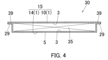
- FIG. 4 is a cross-sectional view showing an electricity storage device manufactured using the exterior material of the embodiment.
- FIG. 5 is a perspective view showing an exploded power storage device of the embodiment.
- FIG. 1 is a cross-sectional view showing an exterior material for an electricity storage device, which is an embodiment of the present invention.
- the exterior material 1 for an electric storage device includes a metal foil layer 4 made of metal foil, and a base layer made of a heat-resistant resin provided on the outer surface side of the metal foil layer 4 and serving as an outer layer. 2, an adhesive layer 5 provided on the inner surface side of the metal foil layer 4, and a thermal adhesive layer (sealant layer) 3 provided on the inner surface side of the adhesive layer 5 and made of a thermal adhesive resin as an inner layer. It has
- the exterior material 1 has the base material layer 2 on the outside and the heat sealing layer 3 on the inside in the state of the exterior case 15 of the electricity storage device 30 .
- the direction of the base layer 2 side is the outside and the heat sealing layer 3 side is the direction in accordance with the inside and outside directions of the exterior case 15.
- the direction is called inner.
- the substrate layer 2 uses a heat-resistant resin such as a biaxially oriented polyamide film, a biaxially oriented polybutylene terephthalate (PBT) film, a biaxially oriented polyethylene terephthalate (PET) film, and a biaxially oriented polyethylene naphthalate (PEN) film.
- a heat-resistant resin such as a biaxially oriented polyamide film, a biaxially oriented polybutylene terephthalate (PBT) film, a biaxially oriented polyethylene terephthalate (PET) film, and a biaxially oriented polyethylene naphthalate (PEN) film.
- PBT biaxially oriented polybutylene terephthalate
- PET biaxially oriented polyethylene terephthalate
- PEN biaxially oriented polyethylene naphthalate
- the polyamide film is not particularly limited, but 6 nylon film, 6,6 nylon film, MXD nylon film and the like can be suitably used.
- the heat-resistant resin constituting the base material layer 2 a heat-resistant resin film that does not melt at the heat-sealing temperature when the exterior material 1 is heat-sealed is used.
- the heat-resistant resin constituting the substrate layer 2 is preferably a thermoplastic resin having a temperature of 10° C. or higher, more preferably 20° C. or higher, with respect to the heat-sealing resin constituting the heat-sealing layer 3. It is preferable to use a thermoplastic resin of
- the thickness of the base material layer 2 is preferably set to 9 ⁇ m to 50 ⁇ m. That is, when the base material layer 2 is adjusted to this thickness, it is possible to secure sufficient strength as the exterior material 1 and to reduce the stress during forming such as stretch forming and draw forming, thereby further improving formability. can.
- a more preferable thickness of the substrate layer 2 is 9 ⁇ m to 30 ⁇ m.
- the base material layer 2 is a multilayer, let total thickness be said thickness.
- the thickness of the adhesive agent which bonds several layers together is also included in said thickness.
- the base material layer 2 may be formed of a single layer, or may be formed of multiple layers as described above.
- multiple layers made of polyester film/polyamide film multiple layers made of PET film/nylon film, etc. can be mentioned.
- the base material layer 2 is a layer that constitutes the outer layer.
- the layer that constitutes the outer layer includes a protective layer that is attached to the outside of the base material layer 2 and a layer that constitutes the outer layer.
- An adhesive layer or the like for bonding can be used.
- the metal foil layer 4 is made of aluminum (Al) foil, copper (Cu) foil, stainless steel (SUS) foil, titanium (Ti) foil, or nickel (Ni) foil.
- a clad material or the like in which metal foil is laminated can be suitably used.
- an aluminum foil can be preferably used as the metal foil layer 4.
- an Al—Fe alloy foil containing 0.7% by mass to 1.7% by mass of Fe has excellent strength and ductility, and therefore can obtain good formability.
- the thickness of the metal foil layer 4 is preferably set to 20 ⁇ m to 150 ⁇ m. That is, when the thickness is 20 ⁇ m or more, it is possible to prevent the occurrence of pinholes during rolling when manufacturing the metal foil, and when it is 150 ⁇ m or less, the stress during forming such as stretch forming and draw forming can be reduced. can improve sexuality.
- a base layer is preferably formed on at least one of the inner and outer surfaces of the metal foil layer 4 .
- the underlayer can be formed by coating with a silane coupling agent or chemical conversion treatment such as chromate treatment.
- the thickness of the underlayer is preferably set to 0.01 ⁇ m to 1 ⁇ m.
- the base layer By forming the base layer in this way, it is possible to improve the adhesive strength with the adhesive layer 5 provided on at least the inner surface of the metal foil layer 4, and effectively prevent the adhesive layer 5 from peeling off. Further, the chemical conversion treatment can sufficiently prevent the corrosion of the metal foil surface due to the contents (electrolyte of the battery, etc.).
- the chemical conversion coating may be selected depending on the combination with the adhesive layer 5, but for example, a coating by chromic acid treatment, a coating by phosphoric acid chromate treatment , a coating by zinc phosphate treatment, a coating by non-chromate treatment using zirconium or titanium as a metal component in place of Cr, and an oxide coating by boehmite treatment can be preferably used.
- the base material layer 2 is attached to the outer surface of the metal foil layer 4 via an adhesive as necessary to be laminated and integrated.
- adhesion formed by a two-liquid curing adhesive is used.
- agents and the like can be suitably used.
- a first liquid consisting of one or more polyols selected from the group consisting of polyurethane-based polyols, polyester-based polyols, polyether-based polyols and polyesterurethane-based polyols, and a second liquid (curing agent) consisting of isocyanate.
- a two-liquid curable adhesive or the like composed of and can be used.
- the thickness of the adhesive layer of this adhesive is preferably set to 2 ⁇ m to 5 ⁇ m.
- the outer layer is composed of multiple layers (including the case where the substrate layer is multiple layers), it is preferable to use the same kind of adhesive.
- the adhesive layer 5 does not necessarily need to be composed of an adhesive, and is composed of, for example, a heat-laminated portion when the heat-sealable layer 5 is directly bonded to the metal foil layer 4 by heat-sealing (heat lamination). You can
- the adhesive layer 5 is composed of an adhesive
- the adhesive includes one or more of polyurethane-based resin, acrylic-based resin, epoxy-based resin, polyolefin-based resin, elastomer-based resin, fluorine-based resin, and acid-modified polypropylene resin.
- Adhesives and the like can be suitably used, and it is particularly preferable to use an adhesive made of a polyurethane composite resin based on acid-modified polyolefin.
- the thickness of the adhesive layer 5 is preferably set to 2 ⁇ m to 5 ⁇ m.
- Thermoplastic resin films constituting the heat-sealing layer 3 include polypropylene-based resin films such as polyethylene, rPP (random polypropylene), bPP (block polypropylene), and hPP (homopolypropylene), particularly CPP (cast polypropylene) and IPP. It is preferable to use an unstretched film such as (inflated polypropylene).
- FIG. 2 is a cross-sectional view showing the heat-sealable layer 3 in the exterior material 1 of this embodiment.
- the thermal adhesive layer 3 is divided into at least two layers, preferably three layers. That is, the inner layer (first layer) of the heat-sealing layer 3 is configured as a seal layer portion 31 that is heat-sealed to another part, and the outer layer (third layer) is bonded to the adhesive layer 5. It is configured as a metal foil side layer portion 33 that More preferably, an intermediate layer portion (second layer) 32 is interposed between the seal layer portion 31 and the metal foil side layer portion 33 .
- the film constituting the heat-sealable layer 3 may be a single-layer film made of one film or a laminated film (co-extruded product, etc.) made of a plurality of films. Considering resistance and insulation, it is preferable to form the laminate film.
- a three-layer coextruded CPP film in which rPP films are arranged on both sides of an hPP film or bPP film can be preferably used.
- the hPP film or bPP film in the middle is configured as the intermediate layer portion 32
- the rPP film on one of both surfaces (inner and outer surfaces) is configured as the sealing layer portion 31.
- the other rPP film is configured as the metal foil side layer portion 33 .
- the sealing layer portion (first layer) 31 in the heat sealing layer 3 is composed of a layer containing coarse particles A and fine particles B
- the metal foil side layer portion (third layer) 33 is composed of fine particles B and does not contain particles having an actual particle size of 5 ⁇ m or more, such as coarse particles A.
- coarse particles A are particles with an average particle size of 5 ⁇ m to 20 ⁇ m.
- the average particle size of the coarse particles A is preferably about half the thickness of the seal layer 31 . That is, if the particle size is too large, the particles tend to come off from the sealing layer 31, and the roughening effect cannot be obtained. Conversely, if the grain size is too small, the grains are buried in the seal layer 31 and the surface roughening effect cannot be obtained.
- metal oxides, resin beads, etc. can be used as the coarse particles A.
- specific examples include silica, alumina, calcium carbonate, barium carbonate, titanium oxide, aluminum silicate, talc, kaolin, acrylic resin beads, polyethylene resin beads, and the like.
- resin beads such as acrylic resin beads, polyethylene resin beads, etc. are preferably used as the coarse particles A, and more preferably.
- Fine particles B are particles with an average particle size of 0.05 ⁇ m or more and less than 5 ⁇ m (not including 5 ⁇ m).
- the average particle diameter of the fine particles B By adjusting the average particle diameter of the fine particles B to the above range, it is possible to form moderate unevenness on the surface of the coarse particles A. If the average particle size of the fine particles B is too large, they may fall off, which is not preferable.
- metal oxides, resin beads, etc. can be used.
- specific examples include silica (Si oxide), alumina (Al oxide), calcium carbonate, barium carbonate, titanium oxide, aluminum silicate, talc, kaolin, acrylic resin beads, polyethylene resin beads, and the like. can.
- metal oxides including silica
- silica such as silica, alumina, and titanium oxide
- the seal layer portion 31 containing the coarse particles A and the fine particles B is formed so that a part of the coarse particles A and the fine particles B extends inward from the inner surface of the resin component such as the rPP film (lower surface in FIGS. 1 and 2) ( ), and the inner surface of the seal layer portion 31 is uneven.
- the average position of the uneven height of the inner surface of the seal layer portion 31 is set as the reference position of the inner surface of the seal layer portion 31, and the reference position and the boundary between the seal layer portion 31 and the intermediate layer portion 32
- the dimension between the positions is defined as the thickness T1 of the seal layer portion 31 . If the intermediate layer portion 32 is not provided, the thickness T1 of the seal layer portion 31 is the dimension between the reference position of the inner surface and the boundary position between the seal layer portion 31 and the metal foil side layer portion 33. .
- the resin beads particularly PE beads, as the coarse particles A and metal oxides, particularly silica, as the fine particles B. That is, even if the resin beads have a large particle size, they are well compatible with the heat-fusible resin (seal layer portion 31) and do not easily fall off. This is because it is held on the surface without falling off.
- the thickness T1 of the seal layer portion 31 it is preferable to set the thickness T1 of the seal layer portion 31 to 5 ⁇ m to 20 ⁇ m. That is, if the thickness T1 is too small, the coarse particles A and the fine particles B are likely to fall off, and as described later, the effect of improving the moldability by the coarse particles A and the fine particles B cannot be sufficiently obtained, which is not preferable. . Conversely, if the thickness T1 of the seal layer portion 31 is too thick, the coarse particles A may be buried in the seal layer portion 31, and the uneven surface roughening effect may not be sufficiently obtained.
- the content of coarse particles A in the seal layer portion 31 is preferably set to 500 ppm to 5000 ppm in mass units. That is, if the content of the coarse particles A is too small, a sufficient surface roughening effect cannot be obtained, and if it is too large, the surface is too rough and tends to fall off, and the surface is too slippery to cause winding misalignment and the like, making handling difficult. It can be difficult.
- the thickness T3 of the metal foil side layer portion 33 it is preferable to set the thickness T3 of the metal foil side layer portion 33 to 5 ⁇ m to 20 ⁇ m. That is, when it is set in this range, the metal foil side layer portion 33 containing the fine particles B can be reliably secured, so as described above, the adhesiveness with the adhesive layer 5 can be improved, and the delamination suppressing effect can be sufficiently achieved. can get to
- the contents of the fine particles B in both the seal layer portion 31 and the metal foil side layer portion 33 are preferably set to 500 ppm to 3500 ppm in mass units. That is, if the content is outside this range, the effect of suppressing delamination due to the inclusion of fine particles B cannot be sufficiently obtained as described later, which is not preferable.
- the intermediate layer portion 32 is preferably made of block polypropylene (bPP film).
- the intermediate layer portion 32 is preferably composed of a layer that does not contain particles having an average particle size of 5 ⁇ m or more. That is, by forming the intermediate layer portion 32 that does not contain particles having a large particle size, electrical insulation and impact resistance can be improved.
- the seal layer portion 31 of the thermal fusion layer 3 contains a lubricant.
- this lubricant examples include saturated fatty acid amides, unsaturated fatty acid amides, substituted amides, methylolamides, saturated fatty acid bisamides, unsaturated fatty acid bisamides, fatty acid ester amides, and aromatic bisamides.
- saturated fatty acid amides include lauric acid amide, palmitic acid amide, stearic acid amide, behenic acid amide, and hydroxystearic acid amide.
- examples of unsaturated fatty acid amides include oleic acid amide and erucic acid amide.
- substituted amides include N-oleyl palmitic acid amide, N-stearyl stearic acid amide, N-stearyl oleic acid amide, N-oleyl stearic acid amide, N-stearyl erucic acid amide and the like.
- methylolamide examples include methylol stearamide and the like.
- saturated fatty acid bisamides include methylenebisstearic acid amide, ethylenebiscapric acid amide, ethylenebislauric acid amide, ethylenebisstearic acid amide, ethylenebishydroxystearic acid amide, ethylenebisbehenic acid amide, hexamethylenebisstearic acid amide. , hexamethylenebisbehenamide, hexamethylenehydroxystearateamide, N,N'-distearyladipamide, N,N'-distearylsebacamide and the like.
- unsaturated fatty acid bisamides include ethylenebisoleic acid amide, ethylenebiserucic acid amide, hexamethylenebisoleic acid amide, N,N'-dioleyladipic acid amide, N,N'-dioleylsebacic acid amide, and the like. can be exemplified.
- stearamide ethyl stearate can be exemplified.
- aromatic bisamides examples include m-xylylenebisstearic acid amide, m-xylylenebishydroxystearic acid amide, and N,N'-stearylisophthalic acid amide.
- the amount of lubricant deposited on the inner surface of the heat-sealable layer 3 is preferably adjusted to 0.1 ⁇ g/cm 2 to 1 ⁇ g/cm 2 . If the amount of lubricant deposited is too small, there is a possibility that good lubricity cannot be obtained, which is not preferable. Conversely, if the amount of the lubricant deposited is too large, the frequency of occurrence of white powder, contamination of equipment, etc. due to the lubricant may increase, which is not preferable. In order to adjust the precipitation amount of the lubricant in the seal layer portion 31 to the specific range described above, it is preferable to set the content of the lubricant to 500 ppm to 5000 ppm. This content is the amount contained when manufacturing the film forming the seal layer portion 31 . This content decreases over time.
- the lubricant is not excessively deposited on the inner surface of the heat-sealing layer 3. can be suppressed, the inner surface of the heat-sealable layer 3 can be covered with the lubricant layer 6 with an appropriate amount of lubricant, and the slipperiness with respect to the forming jig can be further improved.
- the heat-sealable layer 3 of the exterior material 1 of the present embodiment is heat-sealed to another portion, for example, a film
- the positions of the convex portions due to the coarse particles A and the fine particles B are preferentially attached to other portions. Because of the contact, the transfer amount of the lubricant to other parts can also be suppressed.
- the power storage device exterior material 1 of the present embodiment configured as described above is formed into a predetermined shape by cold forming such as deep drawing or stretch forming as it is in a sheet form, or as required. It is used as an exterior case for an electricity storage device.
- FIGS. 4 and 5 are a cross-sectional view and an exploded perspective view showing an electricity storage device 30 manufactured using the exterior material 1 of this embodiment.
- this electric storage device 30 is a lithium ion secondary battery.
- an exterior case 15 is composed of a tray member 14 obtained by molding the exterior material 1 and a cover member 10 made of the planar (sheet-like) exterior material 1 .
- a substantially rectangular parallelepiped electricity storage device main body (electrochemical element or the like) 31 is accommodated in the accommodation recess of the tray member 14 obtained by molding the exterior material 1 of the present invention, and the electricity storage device main body 35
- the lid member 10 (armor material 1) of the present invention is arranged with the heat sealing layer 3 side facing inward (lower side), and the outer peripheral edge of the heat sealing layer 3 of the lid member 10 and , and the heat-sealing layer 3 of the flange portion (sealing peripheral edge portion) 29 of the tray member 14 are heat-sealed and sealed to form the electric storage device 30 .
- the inner surface of the accommodation recess of the tray member 14 is the heat-sealing layer 3
- the outer surface of the accommodation recess is on the substrate layer 2 side.
- reference numeral "39" denotes a heat-sealed portion where the outer peripheral edge portion of the lid member 10 and the flange portion (sealing peripheral edge portion) 29 of the tray member 14 are joined (welded).
- the tip of the tab lead connected to the electricity storage device body 35 is led out of the exterior case 15, but is not shown.
- the power storage device main body 35 is not particularly limited, but includes, for example, a battery main body, a capacitor main body, a capacitor main body, and the like.
- the exterior case 15 is composed of the tray member 14 obtained by molding the exterior material 1 and the planar lid member 10.
- the exterior case 15 may be composed of a pair of planar (sheet-shaped) exterior materials 1, or a pair of tray members 14 may be overlapped in a facing state. It may be configured as follows.
- the sealing layer portion 31 on the inner surface side of the heat sealing layer 3 contains two types of coarse particles A and fine particles B having different particle sizes
- Large and small irregularities are formed on the inner surface of the seal layer part 31 by the coarse particles A and the fine particles B, and the synergistic effect of the large and small irregularities reduces the contact area with the molding jig such as the mold for molding.
- the slipperiness with the molding jig can be improved, the molding can be performed to a sufficient depth, and stable and good molding properties can be obtained. Therefore, even when molding is performed at an almost right angle, such as an internal corner of a molding portion, good moldability can be obtained without causing delamination.
- the metal foil side layer portion 33 on the adhesive layer 5 side of the thermal adhesive layer 3 does not contain large particles having an actual particle size of 5 ⁇ m or more, contact with the adhesive layer 5 is prevented by the large particles.
- the surface is moderately roughened by small particles such as the fine particles B, so that the contact area with the adhesive layer 5 is increased, and the adhesion with the adhesive layer 5 is increased. Therefore, it is possible to reliably suppress the occurrence of delamination.
- the inner surface side of the heat-sealing layer 3 contains a lubricant, it is possible to further improve the slipperiness with respect to a molding jig such as a molding die, thereby stabilizing the stability. Good moldability can be obtained more reliably, and a molded article having a desired shape can be reliably produced.
- the heat-sealable layer 3 in the exterior material 1 of the present embodiment is composed of a film laminate in which two or more films are laminated, the heat-sealable layer 3 having a desired two-layer structure or three-layer structure is formed. It can be reliably formed, and the exterior material 1 of the present invention can be reliably manufactured.
- the amount of lubricant deposited in the heat-sealable layer 3 is small, so it is possible to suppress adverse effects on the battery elements. Therefore, the electric storage device 30 can be reliably charged and discharged, and the operational reliability can be improved.
- the seal layer portion 31 contains 2000 ppm of silica particles having an average particle size of 0.2 ⁇ m (maximum particle size of 2 ⁇ m) as the fine particles B, and HDPE having an average particle size of 12 ⁇ m as the coarse particles A.
- High-density polyethylene It is rPP added with 2000 ppm of beads and 700 ppm of erucamide as a lubricant, and has a layer thickness of 8 ⁇ m.
- the metal foil side layer portion 33 is rPP to which 2000 ppm of silica particles with an average particle size of 0.2 ⁇ m (maximum particle size of 2 ⁇ m) are added as fine particles, and 700 ppm of erucamide is added as a lubricant, and the thickness is 32 ⁇ m.
- Table 4 is a table showing the amount of particles and the amount of lubricant based on actual particle sizes in the seal layer portion 31 and the metal foil side layer portion 33. It corresponds to the diameter. As shown in Table 4, in the seal layer portion 31, 2000 ppm of particles having an actual particle size of 5 ⁇ m or more and 2000 ppm of particles having an actual particle size of less than 5 ⁇ m coexist. Only 2000 ppm of particles with a diameter of less than 5 ⁇ m are present and no particles of 5 ⁇ m or more are present.
- Example 2 As shown in Tables 1 to 4, the same procedure as in Example 1 was performed except that HDPE beads with an average particle diameter of 5 ⁇ m (50% content of particles less than 5 ⁇ m) were added as coarse particles A in the seal layer portion 31. , the film for the heat sealing layer of Example 2 was produced. As shown in Table 4, in this film, the average amount of particles with an actual particle size of 5 ⁇ m or more on the inside (seal layer side) was 1000 ppm, and the average amount of particles with an actual particle size of less than 5 ⁇ m (fine particles B) The abundance becomes 3000 ppm (1000 ppm+2000 ppm).
- Example 3> As shown in Tables 1 to 4, in the same manner as in Example 1 above, except that 3500 ppm of HDPE beads with an average particle diameter of 12 ⁇ m were added as coarse particles A in the seal layer portion 31. For the heat sealing layer of Example 3 A film was produced.
- Example 4 As shown in Tables 1 to 4, in the same manner as in Example 1 above, except that 1200 ppm of HDPE beads with an average particle diameter of 12 ⁇ m were added as coarse particles A in the seal layer portion 31. For the heat sealing layer of Example 4 A film was produced.
- Example 5 As shown in Tables 1 to 4, films for the heat-sealable layer 3 of Example 1 in the exterior material 1 for electric storage devices were produced. That is, as the films of the heat sealing layer 3, the rPP film for the seal layer (first layer) 31, the bPP film with a thickness of 24 ⁇ m for the intermediate layer 32, and the metal foil side layer (third layer) 33 A three-layer coextruded CPP film was made using the rPP film.
- the sealing layer portion 31 is the same as that of Example 1, and the metal foil side layer portion 33 is the same except that the thickness is 8 ⁇ m.
- the intermediate layer (second layer) 32 contains 2000 ppm of silica having an average particle size of 0.2 ⁇ m (maximum particle size of 2 ⁇ m) as fine particles B, and 700 ppm of erucamide as a lubricant.
- a film for a heat sealing layer of Example 5 was produced in the same manner as in Example 1 except for the above.
- Example 6 As shown in Tables 1 to 4, the procedure of Example 5 was repeated except that HDPE beads having an average particle diameter of 5 ⁇ m (50% content of particles less than 5 ⁇ m) were added as coarse particles A in the seal layer portion 31. , the film for the heat sealing layer of Example 6 was produced.
- Example 7 As shown in Tables 1 to 4, the heat sealing layer film of Example 7 was prepared in the same manner as in Example 5 except that HDPE beads having an average particle size of 18 ⁇ m were added as coarse particles A in the seal layer portion 31. was made.
- Example 8> As shown in Tables 1 to 4, LLDPE (linear low-density polyethylene) beads with an average particle size of 5 ⁇ m (50% content of particles of less than 5 ⁇ m) were added as coarse particles A in the seal layer portion 31. A film for heat sealing layer of Example 8 was produced in the same manner as in Example 5 above.
- LLDPE linear low-density polyethylene
- Example 9 As shown in Tables 1 to 4, silica having an average particle size of 0.5 ⁇ m (maximum particle size of 3 ⁇ m) was added as fine particles B in the seal layer portion 31. A film for the heat-sealable layer was produced.
- Example 11 As shown in Tables 1 to 4, the procedure of Example 5 was repeated except that LLDPE having an average particle size of 1 ⁇ m (maximum particle size of 3 ⁇ m) was added as the fine particles B in the sealing layer portion 31 and the metal foil side layer portion 33. , a film for heat sealing layer of Example 11 was produced.
- Example 12 As shown in Tables 1 to 4, the heat sealing layer film of Example 12 was performed in the same manner as in Example 5 except that 3500 ppm of HDPE having an average particle size of 12 ⁇ m was added as coarse particles A in the seal layer portion 31. was made.
- Example 13 As shown in Tables 1 to 4, the heat sealing layer film of Example 13 was performed in the same manner as in Example 5 except that 1200 ppm of HDPE having an average particle size of 12 ⁇ m was added as coarse particles A in the seal layer portion 31. was made.
- Example 14 As shown in Tables 1 to 4, the heat sealing layer film of Example 14 was performed in the same manner as in Example 5 except that 6000 ppm of HDPE having an average particle size of 12 ⁇ m was added as coarse particles A in the seal layer portion 31. was made.
- Example 15 As shown in Tables 1 to 4, the heat sealing layer film of Example 15 was performed in the same manner as in Example 5 except that 300 ppm of HDPE having an average particle size of 12 ⁇ m was added as coarse particles A in the seal layer portion 31. was made.
- Example 16> As shown in Tables 1 to 4, 3000 ppm of HDPE with an average particle size of 12 ⁇ m as coarse particles A and 3000 ppm of silica with an average particle size of 0.2 ⁇ m as fine particles B are added to the seal layer portion 31, and the metal foil side layer portion 33 A film for a heat sealing layer of Example 16 was produced in the same manner as in Example 5 above, except that 3000 ppm of silica having an average particle size of 0.2 ⁇ m was added as fine particles B in .
- Example 17 As shown in Tables 1 to 4, 1000 ppm of HDPE with an average particle size of 12 ⁇ m as coarse particles A and 1000 ppm of silica with an average particle size of 0.2 ⁇ m as fine particles B are added to the seal layer portion 31, and the metal foil side layer portion 31 A film for a heat sealing layer of Example 17 was produced in the same manner as in Example 5 above, except that 1000 ppm of silica having an average particle size of 0.2 ⁇ m was added as fine particles B in .
- Example 5 was carried out in the same manner as in Example 5 except that 4000 ppm of silica having an average particle size of 0.2 ⁇ m was added as fine particles B in the sealing layer portion 31 and the metal foil side layer portion 33 as shown in Tables 1 to 4. 18 films for heat-sealable layers were produced.
- Example 5 was carried out in the same manner as in Example 5 except that 300 ppm of silica having an average particle size of 0.2 ⁇ m was added as fine particles B in the sealing layer portion 31 and the metal foil side layer portion 33 as shown in Tables 1 to 4. No. 19 films for heat-sealable layers were produced.
- Example 20 As shown in Tables 1 to 4, the heat sealing layer film of Example 20 was prepared in the same manner as in Example 5 except that silica having an average particle size of 10 ⁇ m was added as coarse particles A in the seal layer portion 31. made.
- Example 21 As shown in Tables 1 to 4, the heat sealing layer film of Example 21 was prepared in the same manner as in Example 5 above, except that acrylic having an average particle size of 14 ⁇ m was added as coarse particles A in the seal layer portion 31. made.
- Example 22 As shown in Tables 1 to 4, the heat sealing layer film of Example 22 was prepared in the same manner as in Example 5 except that LLDPE having an average particle size of 12 ⁇ m was added as coarse particles A in the seal layer portion 31. made.
- Example 23 As shown in Tables 1 to 4, the seal layer portion 31 has a thickness of 4 ⁇ m added with silica (fine particles B) having an average particle size of 2 ⁇ m, and the metal foil side layer portion 33 has a thickness of 4 ⁇ m.
- a film for thermal adhesive layer of Example 23 was produced in the same manner as in Example 5 above, except that an intermediate layer portion 32 having a thickness of 32 ⁇ m was used.
- Example 24 As shown in Tables 1 to 4, the seal layer portion 31 and the metal foil side layer portion 33 are 6 ⁇ m thick and 4 ⁇ m thick, and the intermediate layer portion 32 is 28 ⁇ m thick.
- a film for heat-sealable layer of Example 24 was produced in the same manner as in Example 5 except that the heat-sealable layer was used.
- Example 25 As shown in Tables 1 to 4, the seal layer portion 31 used had a thickness of 16 ⁇ m, and the metal foil side layer portion 33 and the intermediate layer portion 32 used had a thickness of 12 ⁇ m. A film for heat sealing layer of Example 25 was produced in the same manner as in 5.
- Example 26 As shown in Tables 1 to 4, the seal layer portion 31 has a thickness of 6 ⁇ m, the metal foil side layer portion 33 has a thickness of 26 ⁇ m, and the intermediate layer portion 32 has an average grain size of 10 ⁇ m.
- the thermal fusion of Example 26 was carried out in the same manner as in Example 5 above, except that HDPE (fine particles A) was added at 2000 ppm and silica (coarse particles B) with an average particle diameter of 0.2 ⁇ m was added to have a thickness of 8 ⁇ m. A layering film was produced.
- Example 27 As shown in Tables 1 to 4, the seal layer portion 31 and the intermediate layer portion 32 used had a thickness of 10 ⁇ m, and the metal foil side layer portion 33 used had a thickness of 20 ⁇ m. A film for heat sealing layer of Example 27 was produced in the same manner as in Example 26.
- Example 28 As shown in Tables 1 to 4, the seal layer portion 31 and the metal foil side layer portion 33 were 6 ⁇ m thick, and the intermediate layer portion 32 was 22 ⁇ m thick. A film for heat sealing layer of Example 28 was produced in the same manner as in 5.
- Example 29> As shown in Tables 1 to 4, the seal layer portion 31 and the metal foil side layer portion 33 were 16 ⁇ m thick, and the intermediate layer portion 32 was 48 ⁇ m thick. A film for heat sealing layer of Example 29 was produced in the same manner as in 5.
- Example 30 A film for heat sealing layer of Example 30 was produced in the same manner as in Example 5 above, except that 2500 ppm of lubricant was added to the metal foil side layer portion 33 as shown in Tables 1 to 4.
- Example 31 As shown in Tables 1 to 4, the heat sealing layer portion 31 and the metal foil side layer portion 33 were formed in the same manner as in Example 5 except that 4000 ppm of the lubricant was added. made.
- Example 32 As shown in Tables 1 to 4, the heat sealing layer portion 31 and the metal foil side layer portion 33 were formed in the same manner as in Example 5 except that 100 ppm of a lubricant was added. made.
- Comparative Example 1 As shown in Tables 1 to 4, a film for a heat sealing layer of Comparative Example 1 was produced in the same manner as in Example 1 except that coarse particles A were not added as the seal layer portion 31.
- Comparative Example 2 As shown in Tables 1 to 4, a film for a heat sealing layer of Comparative Example 2 was produced in the same manner as in Example 5 except that coarse particles A were not added as the seal layer portion 31.
- Comparative Example 4 As shown in Tables 1 to 4, Comparative Example 4 was prepared in the same manner as in Comparative Example 3 except that silica (fine particles B) having an average particle size of 3 ⁇ m (maximum particle size of 8 ⁇ m) was added as the sealing layer portion 31. A film for the heat-sealable layer was produced.
- the content of silica (fine particles B) having an actual particle size of 5 ⁇ m or more is 2%, that is, the silica corresponding to 40 ppm has a particle size of 5 ⁇ m or more (see “*1” mark in Table 1). .
- a two-liquid curing urethane adhesive (3 ⁇ m) was applied as a base layer 2 to form a biaxial film having a thickness of 15 ⁇ m.
- An oriented 6 nylon (ONy) film was dry laminated.
- the outer surface of the metal foil side layer portion (third layer) 33 of the CPP film for the heat sealing layer 3 prepared in the above Examples and Comparative Examples is attached to the aluminum foil (metal foil layer) 4 after the dry lamination. It is superimposed on the other surface (inner surface) via a two-component curing adhesive (2 ⁇ m) of maleic acid-modified polypropylene resin and isocyanate, and sandwiched between a rubber nip roll and a lamination roll heated to 100 ° C. Dry lamination was performed by pressing. After that, they were aged at 40° C. for 10 days to obtain exterior materials (laminates) of Examples and Comparative Examples as samples.
- a two-component curing adhesive (2 ⁇ m) of maleic acid-modified polypropylene resin and isocyanate
- the exterior material for an electricity storage device of the present invention is used for batteries and capacitors used in mobile devices such as smartphones and tablets, hybrid vehicles, electric vehicles, wind power generation, solar power generation, and batteries and capacitors used for storing nighttime electricity. It can be suitably used when manufacturing an electric storage device such as.
- Exterior material 10 Lid member (exterior material) 14: Tray member (exterior material) 15: Exterior case (exterior material) 2: Base material layer 3: Thermal adhesive layer 30: Electricity storage device 31: Seal layer portion 32: Intermediate layer portion 33: Metal foil side layer portion 35: Device body portion 4: Metal foil layer 5: Adhesive layer 6: Lubricant layer A: Coarse particles B: Fine particles T1: Thickness of seal layer T3: Thickness of metal foil side layer
Landscapes
- Chemical & Material Sciences (AREA)
- Chemical Kinetics & Catalysis (AREA)
- Electrochemistry (AREA)
- General Chemical & Material Sciences (AREA)
- Engineering & Computer Science (AREA)
- Power Engineering (AREA)
- Microelectronics & Electronic Packaging (AREA)
- Inorganic Chemistry (AREA)
- Materials Engineering (AREA)
- Composite Materials (AREA)
- Manufacturing & Machinery (AREA)
- Laminated Bodies (AREA)
- Sealing Battery Cases Or Jackets (AREA)
- Electric Double-Layer Capacitors Or The Like (AREA)
Priority Applications (6)
| Application Number | Priority Date | Filing Date | Title |
|---|---|---|---|
| EP22892590.5A EP4432429A4 (en) | 2021-11-11 | 2022-10-26 | EXTERIOR MATERIAL FOR ENERGY STORAGE DEVICE AND ENERGY STORAGE DEVICE |
| CN202280074685.7A CN118302902A (zh) | 2021-11-11 | 2022-10-26 | 蓄电装置用外包装材料及蓄电装置 |
| JP2023526054A JP7319484B1 (ja) | 2021-11-11 | 2022-10-26 | 蓄電デバイス用外装材および蓄電デバイス |
| KR1020247014681A KR20240072257A (ko) | 2021-11-11 | 2022-10-26 | 축전 디바이스용 외장재 및 축전 디바이스 |
| JP2023117941A JP2023133392A (ja) | 2021-11-11 | 2023-07-20 | 蓄電デバイス用外装材および蓄電デバイス |
| US18/657,795 US20240291080A1 (en) | 2021-11-11 | 2024-05-08 | Packaging material for power storage device and power storage device |
Applications Claiming Priority (2)
| Application Number | Priority Date | Filing Date | Title |
|---|---|---|---|
| JP2021-183860 | 2021-11-11 | ||
| JP2021183860 | 2021-11-11 |
Related Child Applications (1)
| Application Number | Title | Priority Date | Filing Date |
|---|---|---|---|
| US18/657,795 Continuation US20240291080A1 (en) | 2021-11-11 | 2024-05-08 | Packaging material for power storage device and power storage device |
Publications (1)
| Publication Number | Publication Date |
|---|---|
| WO2023085090A1 true WO2023085090A1 (ja) | 2023-05-19 |
Family
ID=86335656
Family Applications (1)
| Application Number | Title | Priority Date | Filing Date |
|---|---|---|---|
| PCT/JP2022/039897 Ceased WO2023085090A1 (ja) | 2021-11-11 | 2022-10-26 | 蓄電デバイス用外装材および蓄電デバイス |
Country Status (6)
| Country | Link |
|---|---|
| US (1) | US20240291080A1 (https=) |
| EP (1) | EP4432429A4 (https=) |
| JP (2) | JP7319484B1 (https=) |
| KR (1) | KR20240072257A (https=) |
| CN (1) | CN118302902A (https=) |
| WO (1) | WO2023085090A1 (https=) |
Cited By (1)
| Publication number | Priority date | Publication date | Assignee | Title |
|---|---|---|---|---|
| WO2024242142A1 (ja) * | 2023-05-23 | 2024-11-28 | Toppanホールディングス株式会社 | 蓄電装置用外装材及び蓄電装置 |
Citations (7)
| Publication number | Priority date | Publication date | Assignee | Title |
|---|---|---|---|---|
| JP3774163B2 (ja) | 2002-03-28 | 2006-05-10 | 東洋アルミニウム株式会社 | 二次電池容器用積層材及び二次電池容器 |
| JP5380762B2 (ja) | 2005-05-11 | 2014-01-08 | 大日本印刷株式会社 | 電池用包装材 |
| WO2016199754A1 (ja) * | 2015-06-10 | 2016-12-15 | 凸版印刷株式会社 | 蓄電装置用外装材 |
| JP2019061938A (ja) * | 2017-09-28 | 2019-04-18 | 昭和電工パッケージング株式会社 | 蓄電デバイス用外装材、蓄電デバイス用外装ケース及び蓄電デバイス |
| JP2019153556A (ja) * | 2018-03-06 | 2019-09-12 | Tdk株式会社 | 外装体及びこれを用いた電気化学素子 |
| WO2020230629A1 (ja) * | 2019-05-15 | 2020-11-19 | 凸版印刷株式会社 | 蓄電デバイス用外装材 |
| JP2021183860A (ja) | 2020-05-22 | 2021-12-02 | 株式会社デンソー | 減速機付モータ |
Family Cites Families (3)
| Publication number | Priority date | Publication date | Assignee | Title |
|---|---|---|---|---|
| US5380762A (en) | 1993-02-02 | 1995-01-10 | Buckman Laboratories International, Inc. | Method for controlling macroinvertebrates |
| JP4508536B2 (ja) * | 2003-01-30 | 2010-07-21 | 大日本印刷株式会社 | リチウム電池用包装体 |
| CN106042566A (zh) * | 2016-05-30 | 2016-10-26 | 苏州福斯特光伏材料有限公司 | 一种高强度可排气密封层及基于其的锂离子电池软包装材料 |
-
2022
- 2022-10-26 JP JP2023526054A patent/JP7319484B1/ja active Active
- 2022-10-26 WO PCT/JP2022/039897 patent/WO2023085090A1/ja not_active Ceased
- 2022-10-26 CN CN202280074685.7A patent/CN118302902A/zh active Pending
- 2022-10-26 KR KR1020247014681A patent/KR20240072257A/ko active Pending
- 2022-10-26 EP EP22892590.5A patent/EP4432429A4/en active Pending
-
2023
- 2023-07-20 JP JP2023117941A patent/JP2023133392A/ja active Pending
-
2024
- 2024-05-08 US US18/657,795 patent/US20240291080A1/en active Pending
Patent Citations (7)
| Publication number | Priority date | Publication date | Assignee | Title |
|---|---|---|---|---|
| JP3774163B2 (ja) | 2002-03-28 | 2006-05-10 | 東洋アルミニウム株式会社 | 二次電池容器用積層材及び二次電池容器 |
| JP5380762B2 (ja) | 2005-05-11 | 2014-01-08 | 大日本印刷株式会社 | 電池用包装材 |
| WO2016199754A1 (ja) * | 2015-06-10 | 2016-12-15 | 凸版印刷株式会社 | 蓄電装置用外装材 |
| JP2019061938A (ja) * | 2017-09-28 | 2019-04-18 | 昭和電工パッケージング株式会社 | 蓄電デバイス用外装材、蓄電デバイス用外装ケース及び蓄電デバイス |
| JP2019153556A (ja) * | 2018-03-06 | 2019-09-12 | Tdk株式会社 | 外装体及びこれを用いた電気化学素子 |
| WO2020230629A1 (ja) * | 2019-05-15 | 2020-11-19 | 凸版印刷株式会社 | 蓄電デバイス用外装材 |
| JP2021183860A (ja) | 2020-05-22 | 2021-12-02 | 株式会社デンソー | 減速機付モータ |
Non-Patent Citations (1)
| Title |
|---|
| See also references of EP4432429A4 |
Cited By (1)
| Publication number | Priority date | Publication date | Assignee | Title |
|---|---|---|---|---|
| WO2024242142A1 (ja) * | 2023-05-23 | 2024-11-28 | Toppanホールディングス株式会社 | 蓄電装置用外装材及び蓄電装置 |
Also Published As
| Publication number | Publication date |
|---|---|
| EP4432429A4 (en) | 2026-03-25 |
| JP2023133392A (ja) | 2023-09-22 |
| KR20240072257A (ko) | 2024-05-23 |
| EP4432429A1 (en) | 2024-09-18 |
| JPWO2023085090A1 (https=) | 2023-05-19 |
| US20240291080A1 (en) | 2024-08-29 |
| JP7319484B1 (ja) | 2023-08-01 |
| CN118302902A (zh) | 2024-07-05 |
Similar Documents
| Publication | Publication Date | Title |
|---|---|---|
| CN109585706B (zh) | 蓄电设备用外包装材料、蓄电设备用外包装壳体及蓄电设备 | |
| KR102583510B1 (ko) | 축전 디바이스의 외장재용 실런트 필름, 축전 디바이스용 외장재 및 그 제조 방법 | |
| JP6943547B2 (ja) | 蓄電デバイスの外装材用シーラントフィルム、蓄電デバイス用外装材及びその製造方法 | |
| CN110576655B (zh) | 蓄电设备外包装用深拉深成型壳体及蓄电设备 | |
| TWI752039B (zh) | 蓄電裝置之外裝材用密封薄膜、蓄電裝置用外裝材及其製造方法 | |
| JP2021103679A (ja) | 電池の外装材用シーラントフィルム | |
| JP7319484B1 (ja) | 蓄電デバイス用外装材および蓄電デバイス | |
| JP2023160741A (ja) | 蓄電デバイス用包装材、蓄電デバイス用包装ケース及び蓄電デバイス | |
| JP2023075914A (ja) | 蓄電デバイス用外装材 | |
| JP6767795B2 (ja) | 蓄電デバイス用外装材及びその製造方法 | |
| US20260045604A1 (en) | Packaging material for power storage devices | |
| US20230411741A1 (en) | Packaging material for power storage device, packaging case for power storage device, and power storage device | |
| KR20230150201A (ko) | 축전 디바이스용 포장재, 축전 디바이스용 포장 케이스 및 축전 디바이스 | |
| CN111063833A (zh) | 蓄电设备用外包装壳体及其制造方法 | |
| JP2023180219A (ja) | 蓄電デバイス用包装材、蓄電デバイス用包装ケース及び蓄電デバイス | |
| CN110722848A (zh) | 层压材料 | |
| CN117239315A (zh) | 蓄电设备用包装材料、蓄电设备用包装壳体及蓄电设备 | |
| JP7440997B2 (ja) | ラミネート材 | |
| KR20230073987A (ko) | 축전 디바이스용 외장재 | |
| CN116979194A (zh) | 蓄电装置用包装材料、蓄电装置用包装壳体及蓄电装置 | |
| JP2023077398A (ja) | 蓄電デバイス用外装材 | |
| WO2023282056A1 (ja) | 蓄電デバイス用外装材およびその製造方法並びに蓄電デバイス |
Legal Events
| Date | Code | Title | Description |
|---|---|---|---|
| WWE | Wipo information: entry into national phase |
Ref document number: 2023526054 Country of ref document: JP |
|
| 121 | Ep: the epo has been informed by wipo that ep was designated in this application |
Ref document number: 22892590 Country of ref document: EP Kind code of ref document: A1 |
|
| ENP | Entry into the national phase |
Ref document number: 20247014681 Country of ref document: KR Kind code of ref document: A |
|
| WWE | Wipo information: entry into national phase |
Ref document number: 202280074685.7 Country of ref document: CN |
|
| WWE | Wipo information: entry into national phase |
Ref document number: 2022892590 Country of ref document: EP |
|
| NENP | Non-entry into the national phase |
Ref country code: DE |
|
| ENP | Entry into the national phase |
Ref document number: 2022892590 Country of ref document: EP Effective date: 20240611 |