WO2023079643A1 - 車両用冷凍サイクルユニット - Google Patents
車両用冷凍サイクルユニット Download PDFInfo
- Publication number
- WO2023079643A1 WO2023079643A1 PCT/JP2021/040632 JP2021040632W WO2023079643A1 WO 2023079643 A1 WO2023079643 A1 WO 2023079643A1 JP 2021040632 W JP2021040632 W JP 2021040632W WO 2023079643 A1 WO2023079643 A1 WO 2023079643A1
- Authority
- WO
- WIPO (PCT)
- Prior art keywords
- vehicle
- refrigeration cycle
- refrigerant
- heat medium
- space
- Prior art date
- Legal status (The legal status is an assumption and is not a legal conclusion. Google has not performed a legal analysis and makes no representation as to the accuracy of the status listed.)
- Ceased
Links
Images



Classifications
-
- B—PERFORMING OPERATIONS; TRANSPORTING
- B60—VEHICLES IN GENERAL
- B60H—ARRANGEMENTS OF HEATING, COOLING, VENTILATING OR OTHER AIR-TREATING DEVICES SPECIALLY ADAPTED FOR PASSENGER OR GOODS SPACES OF VEHICLES
- B60H1/00—Heating, cooling or ventilating devices
- B60H1/32—Cooling devices
- B60H1/3204—Cooling devices using compression
- B60H1/3228—Cooling devices using compression characterised by refrigerant circuit configurations
- B60H1/32284—Cooling devices using compression characterised by refrigerant circuit configurations comprising two or more secondary circuits, e.g. at evaporator and condenser side
-
- B—PERFORMING OPERATIONS; TRANSPORTING
- B60—VEHICLES IN GENERAL
- B60H—ARRANGEMENTS OF HEATING, COOLING, VENTILATING OR OTHER AIR-TREATING DEVICES SPECIALLY ADAPTED FOR PASSENGER OR GOODS SPACES OF VEHICLES
- B60H1/00—Heating, cooling or ventilating devices
- B60H1/00642—Control systems or circuits; Control members or indication devices for heating, cooling or ventilating devices
- B60H1/00978—Control systems or circuits characterised by failure of detection or safety means; Diagnostic methods
-
- B—PERFORMING OPERATIONS; TRANSPORTING
- B60—VEHICLES IN GENERAL
- B60H—ARRANGEMENTS OF HEATING, COOLING, VENTILATING OR OTHER AIR-TREATING DEVICES SPECIALLY ADAPTED FOR PASSENGER OR GOODS SPACES OF VEHICLES
- B60H1/00—Heating, cooling or ventilating devices
- B60H1/32—Cooling devices
- B60H1/3204—Cooling devices using compression
- B60H1/3205—Control means therefor
- B60H1/3217—Control means therefor for high pressure, inflamable or poisonous refrigerants causing danger in case of accidents
Definitions
- the present disclosure relates to a vehicle refrigeration cycle unit.
- Patent Document 1 there are devices such as a compressor, a heat medium cooler (evaporator), and a heat medium heater (condenser) that are housed in a heat insulating case, and a heat management system for vehicles.
- a compressor a heat medium cooler (evaporator), and a heat medium heater (condenser) that are housed in a heat insulating case, and a heat management system for vehicles.
- a constituent refrigeration cycle is disclosed.
- the primary refrigerant may leak from the device due to long-term use.
- the compressor, evaporator, and condenser of the refrigeration cycle described in Patent Literature 1 are housed within a case in spaces defined by partition walls of the case. Therefore, for example, when the primary refrigerant leaks from any one of these, there is a problem that it is difficult to grasp the presence or absence of leakage.
- the present disclosure has been made to solve the above problems, and an object thereof is to provide a vehicular refrigeration cycle unit capable of grasping the presence or absence of leakage of the primary refrigerant.
- a vehicle refrigeration cycle unit is interposed between an exterior heat exchanger and an interior heat exchanger, and circulates between the exterior heat exchanger and the interior heat exchanger.
- a refrigerating cycle unit for a vehicle that exchanges heat between secondary refrigerants, and is provided in an equipment housing space inside a vehicle, and a compressor, a condenser, and a flammable primary refrigerant having a specific gravity greater than air flow sequentially.
- a refrigerating cycle having an expansion valve and an evaporator, and a leakage located below the compressor, the condenser, and the evaporator and capable of detecting the concentration of the primary refrigerant contained in the atmosphere within the equipment housing space. a sensor;
- a vehicular refrigeration cycle unit capable of grasping the presence or absence of leakage of the primary refrigerant.
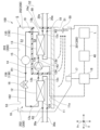
- FIG. 1 is a system diagram showing the configuration of a vehicle air conditioner (during heating operation) according to an embodiment;
- FIG. It is a figure which shows the structure of the refrigerating-cycle unit for vehicles which concerns on embodiment.
- 4 is a flow chart showing the operation of the refrigerating cycle side control device according to the embodiment;
- 1 is a hardware configuration diagram showing the configuration of a computer according to an embodiment;
- FIG. 1 is a system diagram showing a configuration of a vehicle air conditioner (during cooling operation) according to an embodiment;
- vehicle air conditioner A vehicle air conditioner is a device mounted in an electric vehicle or the like, and conditions the air inside the vehicle. This vehicle air conditioner adjusts the temperature difference between the inside and outside of the vehicle body. In the present embodiment, a configuration in which the vehicle air conditioner performs heating operation will be described as an example.
- the vehicle air conditioner 1 includes a vehicle refrigeration cycle unit 100 , a vehicle interior heat medium circuit 20 , and a vehicle exterior heat medium circuit 30 .
- the lines in an open state through which the refrigerant can flow are indicated by solid lines.
- lines in a closed state in which the refrigerant cannot flow are indicated by dashed lines.
- black paint indicates a closed state
- white paint indicates an open state.
- the vehicle refrigeration cycle unit 100 is provided inside the equipment housing space S inside the vehicle C.
- the equipment accommodation space S in this embodiment is, for example, a front compartment located on the front side of the vehicle C.
- the equipment accommodation space S is a front compartment, of the vehicle body inner wall 200 forming the equipment accommodation space S, the bottom wall portion 201 having the bottom surface and the side wall portion 202 having the side surfaces are formed of metal or the like.
- a metal bonnet 203 capable of blocking the equipment accommodation space S from above is provided above the equipment accommodation space S defined by the bottom wall portion 201 and the side wall portion 202 . That is, the bonnet 203 corresponds to the ceiling of the vehicle body inner wall 200 which makes the equipment accommodation space S a closed space.
- a side wall portion 202 of the vehicle interior wall 200 is formed with a hole portion 60 that allows communication between the equipment housing space S and the atmosphere outside the vehicle C. As shown in FIG.
- the vehicle refrigerating cycle unit 100 is a device that circulates a primary refrigerant R1 for exchanging heat with a secondary refrigerant R2 used for air conditioning in the vehicle.
- a primary refrigerant R1 in this embodiment for example, R290 refrigerant (propane), which is a highly flammable (combustible) hydrocarbon with a specific gravity greater than that of air, is employed.
- the vehicle refrigeration cycle unit 100 includes a base plate 11, a refrigeration cycle 10, various lines (a suction line 124, a discharge line 143, a pre-expansion line 136, and a post-expansion line 162), a casing 19, a leak sensor 17, It has a first scavenging port 51, a fan 50, an intake port 53, a second scavenging port 52, and a refrigerating cycle side control device 18 (control device).
- the base plate 11 is a plate-like member provided in the equipment housing space S. As shown in FIG.
- the base plate 11 has a main surface 11a facing upward in the vertical direction Dv, which is the direction that corresponds to the direction of gravity. In other words, the base plate 11 extends in the horizontal direction H perpendicular to the vertical direction Dv such that the main surface 11a faces upward.
- a metal, a synthetic resin, or the like is adopted as a material forming the base plate 11 .
- a refrigerating cycle 10 is composed of a plurality of devices that realize a thermodynamic cycle.
- the refrigeration cycle 10 repeatedly compresses, expands, evaporates, and condenses the primary refrigerant R1 in order to exchange heat between the primary refrigerant R1 as a heat medium and the secondary refrigerant R2, while sequentially circulating the primary refrigerant R1 through a plurality of devices. It is a refrigerant circuit that circulates.
- the refrigerating cycle 10 is provided within the equipment housing space S.
- the refrigeration cycle 10 has an evaporator 12 , a compressor 14 , a condenser 13 , a receiver 15 and an expansion valve 16 . These are sequentially connected by piping through which the primary refrigerant R1 flows.
- the evaporator 12 evaporates (vaporizes) the primary refrigerant R1 by exchanging heat between the primary refrigerant R1 that sequentially flows through the refrigeration cycle 10 and the secondary refrigerant R2 that is introduced from the outside of the vehicle refrigeration cycle unit 100. It is a plate heat exchanger that allows The primary refrigerant R1 inside the evaporator 12 is warmed by the secondary refrigerant R2 and at the same time cools the secondary refrigerant R2. Although not shown in FIG. 2 for convenience, the evaporator 12 is fixed to the main surface 11 a of the base plate 11 .
- the compressor 14 is a device that compresses the primary refrigerant R1 vaporized through the evaporator 12 .
- the pressure of the primary refrigerant R1 introduced into the compressor 14 is increased by compression of the compressor 14 to a predetermined pressure higher than before compression. As a result, the temperature of the primary refrigerant R1 rises above that before compression.
- the compressor 14 is fixed to the main surface 11 a of the base plate 11 .
- the compressor 14 and the evaporator 12 are connected by a suction line 124. That is, one end of the suction line 124 is connected to the primary refrigerant outlet 12 b of the evaporator 12 , and the other end of the suction line 124 is connected to the suction port of the compressor 14 .
- the condenser 13 exchanges heat between the primary refrigerant R1, which has a higher temperature and pressure than before being compressed by passing through the compressor 14, and the secondary refrigerant R2 introduced from the outside of the vehicle refrigeration cycle unit 100.
- the plate heat exchanger condenses (liquefies) the primary refrigerant R1.
- the primary refrigerant R1 inside the condenser 13 is cooled by the secondary refrigerant R2 and at the same time warms the secondary refrigerant R2.
- the condenser 13 is fixed to the main surface 11 a of the base plate 11 .
- the condenser 13 and the compressor 14 are connected by a discharge line 143. That is, one end of the discharge line 143 is connected to the discharge port of the compressor 14 , and the other end of the discharge line 143 is connected to the primary refrigerant inlet portion 13 a of the condenser 13 .
- the receiver 15 receives the primary refrigerant R1 that has become a gas-liquid mixed fluid by passing through the condenser 13, separates the primary refrigerant R1 into a gas phase and a liquid phase, and temporarily stores them inside. It is a holding gas-liquid separator.
- the receiver 15 and the condenser 13 are connected by the first line 135 of the pre-expansion line 136 . That is, one end of the first line 135 is connected to the primary refrigerant outlet portion 13 b of the condenser 13 , and the other end of the first line 135 is connected to the refrigerant inlet portion located at the lower end of the receiver 15 .
- the receiver 15 is supported by the first line 135 connected to the condenser 13, and is held at a position separated from the main surface 11a of the base plate 11, for example.
- the gas-liquid mixed primary refrigerant R1 introduced into the receiver 15 flows into the liquid phase portion stored inside the receiver 15 .
- the liquid portion of the primary refrigerant R1 that has flowed in is added to the liquid phase, and the remaining gas portion forms bubbles that move upward inside the receiver 15 and are added to the gas phase.
- the primary refrigerant R1 stored as a liquid phase inside the receiver 15 is discharged outside the receiver 15 . As a result, the primary refrigerant R1 in a liquid state is always provided from the receiver 15 .
- the expansion valve 16 is a device that receives the primary refrigerant R1 in a liquid state through the receiver 15 and adiabatically expands the primary refrigerant R1.
- the expansion valve 16 and the receiver 15 are connected by the second line 156 of the pre-expansion line 136 . That is, one end of the second line 156 is connected to the refrigerant outlet of the receiver 15 and the other end of the second line 156 is connected to the expansion valve 16 .
- the pressure of the primary refrigerant R1 introduced into the expansion valve 16 is lowered to a predetermined pressure lower than before expansion due to the expansion action of the expansion valve 16.
- the temperature of the primary refrigerant R1 is lower than before expansion.
- the primary refrigerant R1 that has passed through the expansion valve 16 becomes a two-phase fluid, and is lowered to a temperature lower than the temperature of the secondary refrigerant R2 that is the destination of heat exchange.
- the expansion valve 16 and the evaporator 12 are connected by a post-expansion line 162 , and the primary refrigerant R1 that has passed through the expansion valve 16 is introduced into the evaporator 12 through this post-expansion line 162 . That is, one end of the post-expansion line 162 is connected to the expansion valve 16 , and the other end of the post-expansion line 162 is connected to the primary refrigerant inlet portion 12 a of the evaporator 12 .
- the expansion valve 16 is supported by this post-expansion line 162 connected to the evaporator 12, and is held at a position separated from the main surface 11a of the base plate 11, for example.
- the casing 19 hermetically separates the equipment housing space S into a first space S1 on the outside and a second space S2 on the inside, and houses the compressor 14 and the condenser 13 in the second space S2. That is, the first space S ⁇ b>1 and the second space S ⁇ b>2 are nested by the casing 19 .
- Casing 19 is fixed to main surface 11 a of base plate 11 .
- the casing 19 is a heat insulating material provided between the compressor 14 and the condenser 13 and other devices of the refrigeration cycle 10 within the equipment housing space S. Rubber, resin, or the like, for example, is adopted as the material forming the casing 19 .
- This casing 19 suppresses the movement of the atmosphere from the second space S2 to the first space S1 and the direct movement (heat conduction) of heat from the second space S2 to the first space S1 via the atmosphere. ing.
- a portion of the outer surface of the casing 19 in this embodiment (the right side portion of the casing 19 shown in FIG. 2) is joined to the side surface of the side wall portion 202 .
- a casing hole 19a is formed through the casing 19 from the inside toward the inner wall surface to which it is joined.
- the casing hole 19 a has the same shape and size as the hole 60 formed in the vehicle body inner wall 200 and is arranged to correspond to (overlap with) the hole 60 .
- the leakage sensor 17 is a gas sensor capable of detecting the concentration of the primary refrigerant R1 contained in the atmosphere inside the housing space.
- the leak sensor 17 is provided in the equipment housing space S and positioned below the compressor 14, the condenser 13, and the evaporator 12 of the refrigerating cycle 10 (on the lower side in the vertical direction Dv). Specifically, the leak sensor 17 is provided on the bottom surface of the bottom wall portion 201 .
- the leakage sensor 17 detects the concentration of the primary refrigerant R1 contained in the atmosphere inside the housing space at predetermined time intervals, and transmits a signal indicating this concentration to the outside through a cable (wire harness) or the like.
- a semiconductor gas sensor capable of detecting R290 refrigerant is adopted as the leakage sensor 17 in this embodiment.
- a specific example is TGS2610-D00 (LP gas sensor) manufactured by Figaro Engineering Co., Ltd.
- the first scavenging port 51 is an air flow path that allows the equipment housing space S and the atmosphere outside the vehicle C to communicate with each other.
- the first scavenging port 51 is located below the compressor 14 , the condenser 13 and the evaporator 12 of the refrigeration cycle 10 .
- the first scavenging port 51 in this embodiment is a hole formed in the side wall portion 202 of the vehicle body inner wall 200 .
- the fan 50 is a fan 50 capable of discharging the atmosphere in the equipment housing space S to the atmosphere outside the vehicle C through the first scavenging port 51 .
- the fan 50 is provided at the first scavenging port 51 . That is, the fan 50 in this embodiment sends the atmosphere in the first space S1 of the equipment housing space S to the outside of the vehicle C. As shown in FIG.
- the intake port 53 is an air flow path that communicates the equipment housing space S with the atmosphere outside the vehicle C independently of the first scavenging port 51 .
- the intake port 53 is located above the compressor 14 , the condenser 13 , and the evaporator 12 of the refrigerating cycle 10 (upper side in the vertical direction Dv).
- the intake port 53 in this embodiment is, for example, a hole formed in the bonnet 203 .
- Intake port 53 may be a gap defined by a gap between bonnet 203 and side wall portion 202 .
- the fan 50 sends the atmosphere in the first space S1 toward the atmosphere through the first scavenging port 51, the air outside the vehicle C (atmosphere) is introduced into the equipment housing space S through the intake port 53. This realizes ventilation of the atmosphere in the first space S1.
- the second scavenging port 52 is configured by a combination of a casing hole 19 a formed in the casing 19 and a hole 60 formed in the vehicle body inner wall 200 . That is, the second scavenging port 52 is an air flow path that communicates the second space S2 inside the casing 19 with the atmosphere outside the vehicle C without passing through the first space S1.
- the refrigerating cycle controller 18 is a device that stops the operation of the compressor 14 of the refrigerating cycle 10 and drives the fan 50 based on the detection information from the leak sensor 17 .
- the refrigerating cycle controller 18 is connected to the leakage sensor 17, the compressor 14 of the refrigerating cycle 10, and a vehicle controller 40 constituting an engine control unit provided inside the vehicle C by a cable (wire harness) or the like.
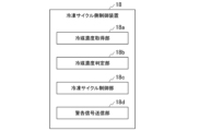
- the refrigerating cycle side control device 18 includes a refrigerant concentration acquiring section 18a, a refrigerant concentration determining section 18b, a refrigerating cycle control section 18c, and a warning signal transmitting section 18d.
- the refrigerant concentration acquisition unit 18a receives a signal transmitted from the leakage sensor 17, and acquires the concentration of the primary refrigerant R1 contained in the atmosphere inside the equipment housing space S from this signal.
- the refrigerant concentration determination unit 18b determines whether or not the primary refrigerant R1 is leaking within the equipment housing space S based on the concentration of the primary refrigerant R1 acquired by the refrigerant concentration acquisition unit 18a. Specifically, the refrigerant concentration determination unit 18b determines whether or not the concentration of the primary refrigerant R1 acquired by the refrigerant concentration acquisition unit 18a is equal to or greater than a predetermined threshold.
- the predetermined threshold here means the upper limit of the safe concentration range in which the primary refrigerant R1 does not explode due to fire or the like.
- An example of the upper limit of the safe concentration range in the present embodiment is the Lower Explosion Limit (LEL) of the primary refrigerant R1. If the primary refrigerant R1 is R290 refrigerant, the lower explosive limit is 2.1%. On the other hand, the lower limit of the safe concentration range is 0%. Therefore, the safe concentration range in this embodiment is 0% or more and less than 2.1%.
- LEL Lower Explosion Limit
- the refrigeration cycle control unit 18c stops the operation of the refrigeration cycle 10 and drives the fan 50 when the refrigerant concentration determination unit 18b determines that the concentration of the primary refrigerant R1 is equal to or higher than a predetermined threshold value. Specifically, the refrigerating cycle control unit 18 c sends a signal indicating an instruction to start driving to the fan 50 after sending a signal indicating an instruction to stop operation to the compressor 14 .
- Compressor 14 stops operation when receiving a signal indicating an instruction to stop operation from refrigeration cycle control unit 18c.
- the fan 50 is driven when receiving a signal indicating an instruction to start driving from the refrigerating cycle control section 18c. In other words, the fan 50 starts sending the atmosphere in the equipment housing space S toward the atmosphere through the first scavenging port 51 .
- the warning signal transmission unit 18d transmits a signal representing a warning to the vehicle-side control device 40 when the refrigeration cycle control unit 18c transmits a signal representing an instruction to stop operation to the compressor 14 .
- the vehicle-side control device 40 receives a warning signal from the warning signal transmission unit 18d, the vehicle-side control device 40 transmits a lighting instruction signal to the in-vehicle warning light L provided in the driver's seat or the like inside the vehicle C.
- the in-vehicle warning light L starts lighting when a signal instructing lighting is received from the vehicle-side control device 40 .
- the refrigerant concentration acquisition unit 18a acquires the concentration of the primary refrigerant R1.
- the refrigerant concentration determination unit 18b determines whether or not the primary refrigerant R1 is leaking inside the device housing space S (step S1).
- the refrigeration cycle control unit 18c transmits a signal indicating an operation stop instruction to the compressor . That is, the refrigerating cycle control unit 18c stops the operation of the compressor 14 (step S2).
- the refrigerant concentration determination unit 18b determines that there is no leakage (step S1; NO)
- the process returns to step S1.
- the warning signal transmitting section 18d transmits a signal indicating a warning to the vehicle-side control device 40 (step S3).
- the refrigerating cycle control section 18c transmits to the fan 50 a signal indicating an instruction to start driving. That is, the refrigerating cycle control section 18c drives the fan 50 (step S4).
- the refrigerant concentration determination unit 18b determines whether the concentration of the primary refrigerant R1 is equal to or higher than a predetermined threshold. That is, the refrigerant concentration determination unit 18b determines whether or not the concentration of the primary refrigerant R1 contained in the atmosphere within the equipment housing space S is within the safe concentration range (step S5).
- step S5 When it is determined that the concentration of the primary refrigerant R1 is within the safe concentration range (step S5; YES), the refrigeration cycle control unit 18c transmits a signal to the fan 50 to instruct the fan 50 to stop driving. That is, the refrigerating cycle control unit 18c stops driving the fan 50 (step S6).
- step S5 When the driving of the fan 50 stops, the operation of the refrigerating cycle controller 18 ends. On the other hand, if it is determined that the concentration of the primary refrigerant R1 is not within the safe concentration range (step S5; NO), the process returns to step S4.
- the vehicle-side heat medium circuit 20 is a refrigerant circuit for circulating the secondary refrigerant R2 heat-exchanged with the primary refrigerant R1 in the refrigerating cycle 10 and for conditioning the air inside the vehicle.
- An antifreeze liquid such as ethylene glycol is used as the secondary refrigerant R2 in the present embodiment.
- the vehicle-interior heat medium circuit 20 includes a heater core 21a (interior heat exchanger 21), a cooler core 21b (interior heat exchanger 21), a first pump 22, a first valve 23, and a second It has two valves 24 and various lines (first heating medium line 20a to seventh heating medium line 20g).
- the heater core 21a and the cooler core 21b are heat exchangers for exchanging heat between the indoor air inside the vehicle C, the outdoor air outside the vehicle C, and the secondary refrigerant R2.
- the secondary refrigerant R2 that has passed through the condenser 13 of the vehicle refrigeration cycle unit 100 is introduced into the heater core 21a.
- the secondary refrigerant R2 passes through the first pump 22 and the first valve 23 during the process of introducing the secondary refrigerant R2 from the condenser 13 to the heater core 21a.
- the first pump 22 is a pump that pressure-feeds the secondary refrigerant R2 heated by the condenser 13 to the heater core 21a.
- a first heat medium line 20 a as a flow path for sucking the secondary refrigerant R ⁇ b>2 into the first pump 22 connects the condenser 13 and the first pump 22 . That is, one end of the first heat medium line 20a is connected to the secondary refrigerant outlet 13d of the condenser 13, and the other end of the first heat medium line 20a is connected to the refrigerant suction port of the first pump 22. ing.
- the second heat medium line 20b as a flow path for discharging the secondary refrigerant R2 from the first pump 22 toward the heater core 21a connects the first pump 22 and the first valve 23. That is, one end of the second heat medium line 20b is connected to the refrigerant discharge port of the first pump 22, and the other end of the second heat medium line 20b is connected to the first valve .
- the first valve 23 is a three-way valve that can change the flow path (destination) of the secondary refrigerant R2.
- the first valve 23 and the heater core 21a are connected by a third heat medium line 20c. That is, one end of the third heat medium line 20c is connected to the first valve 23, and the other end of the third heat medium line 20c is connected to the heater core 21a.
- the secondary refrigerant R2 introduced into the heater core 21a is cooled by exchanging heat with the indoor air inside the vehicle C and the outdoor air introduced from the outside of the vehicle C, and at the same time, warms the indoor air and the outdoor air. .
- This allows the air inside the vehicle to be warmed.
- the outdoor air for example, the outside air outside the vehicle body introduced by a blower (not shown) arranged upstream of the cooler core 21b is used.
- the secondary refrigerant R2 cooled in the heater core 21a is returned to the condenser 13 via the second valve 24.
- the second valve 24 is a three-way valve that can change the flow path (destination) of the secondary refrigerant R2.
- the second valve 24 and the heater core 21a are connected by a fourth heating medium line 20d. That is, one end of the fourth heat medium line 20 d is connected to the refrigerant outlet of the heater core 21 a, and the other end of the fourth heat medium line 20 d is connected to the second valve 24 .
- the second valve 24 and the condenser 13 are connected by a fifth heat medium line 20e. That is, one end of the fifth heat medium line 20 e is connected to the second valve 24 and the other end of the fifth heat medium line 20 e is connected to the secondary refrigerant inlet 13 c of the condenser 13 .
- the secondary refrigerant R2 sequentially flows through the condenser 13, the first pump 22, and the heater core 21a, and returns to the condenser 13. By repeating this circulation, the heating operation is realized, and the temperature inside the vehicle can be kept warm.
- the cooler core 21b is provided inside the vehicle body independently of the heater core 21a.
- the secondary refrigerant R2 that has passed through the evaporator 12 is introduced into the cooler core 21b during the cooling operation, and heat is exchanged between the secondary refrigerant R2 and the outside air. The flow of the secondary refrigerant R2 during the cooling operation will be described later.
- the vehicle-exterior heat medium circuit 30 is a refrigerant circuit for circulating the secondary refrigerant R2 heat-exchanged with the primary refrigerant R1 in the refrigerating cycle 10 and for cooling the battery for driving the vehicle body.
- the outside heat medium circuit 30 includes an outside heat exchanger 31, a second pump 32, various valves (third valve 33 and fifth valve 35), a battery cooler 36, and various lines (eighth heat medium line 30a to a twelfth heat medium line 30e, and a first connection line 30f to a fourth connection line 30i).
- the outside heat exchanger 31 is a heat exchanger for exchanging heat between the outside air and the secondary refrigerant R2. Part of the secondary refrigerant R2 that has passed through the evaporator 12 of the vehicle refrigeration cycle unit 100 is introduced into the external heat exchanger 31 via the third valve 33 . The remaining portion of the secondary refrigerant R2 that has passed through the evaporator 12 is introduced into the battery cooler 36 via the fourth valve 34 .
- the evaporator 12, the third valve 33 and the fourth valve 34 are connected by an eighth heat medium line 30a.
- one end of the eighth heat medium line 30a is connected to the secondary refrigerant outlet 12d of the evaporator 12, and the other end of the eighth heat medium line 30a is connected to the middle of the eighth heat medium line 30a. It branches in two directions and is connected to the third valve 33 and the fourth valve 34, respectively.
- These third valve 33 and fourth valve 34 are three-way valves capable of changing the flow path (destination) of the secondary refrigerant R2.
- the third valve 33 and the external heat exchanger 31 are connected by a ninth heat medium line 30b. That is, one end of the ninth heat medium line 30 b is connected to the third valve 33 , and the other end of the ninth heat medium line 30 b is connected to the refrigerant inlet portion of the external heat exchanger 31 .
- the secondary refrigerant R2 introduced into the exterior heat exchanger 31 through the eighth heat medium line 30a, the third valve 33, and the ninth heat medium line 30b is warmed by exchanging heat with the outside air.
- the temperature of the secondary refrigerant R2 becomes higher than that of the primary refrigerant R1 introduced into the evaporator 12, and the primary refrigerant R1 flowing through the refrigeration cycle 10 can be warmed within the evaporator 12.
- Outside air to which heat is exchanged by the exterior heat exchanger 31 is sucked from the outside of the vehicle body through the front grille F by the blower B provided on the front side inside the vehicle C. As shown in FIG.
- the second pump 32 is a pump that pressure-feeds the secondary refrigerant R2 warmed by the external heat exchanger 31 to the evaporator 12.
- the secondary refrigerant R2 that has passed through the external heat exchanger 31 passes through the fifth valve 35 in the course of being sucked into the second pump 32 .
- the fifth valve 35 is a three-way valve capable of changing the flow path (destination) of the secondary refrigerant R2.
- the fifth valve 35 and the external heat exchanger 31 are connected by a tenth heat medium line 30c. That is, one end of the tenth heat medium line 30 c is connected to the external heat exchanger 31 , and the other end of the tenth heat medium line 30 c is connected to the fifth valve 35 .
- An eleventh heat medium line 30 d as a flow path for sucking the secondary refrigerant R2 into the second pump 32 connects the fifth valve 35 and the second pump 32 . That is, one end of the eleventh heating medium line 30 d is connected to the fifth valve 35 and the other end of the eleventh heating medium line 30 d is connected to the second pump 32 .
- the second pump 32 and the evaporator 12 are connected by a twelfth heat medium line 30e. That is, one end of the twelfth heat medium line 30e is connected to the second pump 32, and the other end of the twelfth heat medium line 30e is connected to the secondary refrigerant inlet portion 12c of the evaporator 12. .
- the secondary refrigerant R2 pressure-fed by the second pump 32 is thereby introduced into the evaporator 12 .
- the secondary refrigerant R2 flows through the evaporator 12, the outside heat exchanger 31, and the second pump 32 in sequence, and returns to the evaporator 12.
- the primary refrigerant R1 circulating in the refrigeration cycle 10 can be continuously warmed by heat exchange in the evaporator 12 .
- the vehicle refrigerating cycle unit 100 is interposed between the vehicle exterior heat exchanger 31 and the heater core 21a (vehicle heat exchanger 21), and the two heat exchangers circulating through the vehicle exterior heat exchanger 31 and the vehicle interior heat exchanger 21, respectively. Heat is exchanged between the next refrigerants R2.
- the battery cooler 36 is a heat exchanger for cooling the battery.
- the battery cooler 36 is provided inside the vehicle C.
- the remainder of the secondary refrigerant R2 cooled by the evaporator 12 and flowing through the eighth heat medium line 30a is introduced into the battery cooler 36 via the fourth valve 34 .
- the fourth valve 34 and the battery cooler 36 are connected by a first connection line 30f. That is, one end of the first connection line 30 f is connected to the fourth valve 34 , and the other end of the first connection line 30 f is connected to the coolant inlet of the battery cooler 36 .
- the secondary refrigerant R2 warmed by heat exchange with the battery (not shown) in the battery cooler 36 is returned to the evaporator 12.
- the battery cooler 36 and the eleventh heating medium line 30d are connected by a second connection line 30g.
- one end of the second connection line 30g is connected to the refrigerant outlet of the battery cooler 36, and the other end of the second connection line 30g is connected to the second pump 32 in the eleventh heat medium line 30d. is connected to a portion closer to the fifth valve 35 than the Therefore, the secondary refrigerant R2 that has passed through the battery cooler 36 joins the eleventh heating medium line 30d via the second connection line 30g, and is pressure-fed to the evaporator 12 again by the second pump 32.
- the fourth valve 34 and the cooler core 21b are connected by a sixth heat medium line 20f. That is, one end of the sixth heat medium line 20f is connected to the fourth valve 34, and the other end of the sixth heat medium line 20f is connected to the refrigerant inlet of the cooler core 21b.
- the cooler core 21b and the second connection line 30g are connected by a seventh heat medium line 20g. That is, one end of the seventh heat medium line 20g is connected to the cooler core 21b, and the other end of the seventh heat medium line 20g is connected to the second connection line 30g. Therefore, the secondary refrigerant R2 that has passed through the evaporator 12 during cooling operation of the vehicle air conditioner 1 can flow into the cooler core 21b via the fourth valve 34 .
- the fourth valve 34 allows the secondary refrigerant R2 flowing from the eighth heat medium line 30a to flow only to the first connection line 30f without flowing to the sixth heat medium line 20f. That is, the fourth valve 34 supplies the secondary coolant R2 only to the battery cooler 36 without supplying it to the cooler core 21b.
- first valve 23 and the fifth valve 35 are connected by a third connection line 30h. That is, one end of the third connection line 30 h is connected to the first valve 23 and the other end of the third connection line 30 h is connected to the fifth valve 35 .
- the first valve 23 allows the secondary refrigerant R2 flowing from the second heat medium line 20b to flow only to the third heat medium line 20c without flowing to the third connection line 30h.
- the fifth valve 35 allows the secondary refrigerant R2 flowing from the tenth heat medium line 30c to flow only to the eleventh heat medium line 30d without flowing to the third connection line 30h.
- the second valve 24 and the third valve 33 are connected by a fourth connection line 30i. That is, one end of the fourth connection line 30 i is connected to the second valve 24 and the other end of the fourth connection line 30 i is connected to the third valve 33 .
- the second valve 24 allows the secondary refrigerant R2 flowing from the fourth heat medium line 20d to flow only to the fifth heat medium line 20e without flowing to the fourth connection line 30i.
- the third valve 33 allows the secondary refrigerant R2 flowing from the eighth heat medium line 30a to flow only to the ninth heat medium line 30b without flowing to the fourth connection line 30i.
- the vehicular refrigeration cycle unit 100 can detect the concentration of the primary refrigerant R1 in the atmosphere in the equipment housing space S below the compressor 14, the condenser 13, the expansion valve 16, and the evaporator 12.
- a leak sensor 17 is provided.
- the leakage sensor 17 detects the concentration of the primary refrigerant R1 as the leaked primary refrigerant R1 descends. A rise is detected. Therefore, based on the concentration detected by the leakage sensor 17, it is possible to ascertain whether or not the primary refrigerant R1 is leaking.
- the vehicular refrigeration cycle unit 100 includes the first scavenging port 51 and the fan 50 capable of discharging the atmosphere in the equipment housing space S to the atmosphere outside the vehicle C through the first scavenging port 51. It has As a result, the leaked flammable primary refrigerant R1 can be positively discharged to the atmosphere without remaining in the equipment housing space S. Therefore, the inside of the equipment housing space S can be kept safe.
- the control device stops the operation of the compressor 14 and drives the fan 50 based on the detection information of the leak sensor 17 .
- the primary refrigerant R1 in the equipment housing space S can be discharged to the atmosphere at the required timing, and the control device stops the operation of the compressor 14, thereby suppressing further leakage of the primary refrigerant R1. can be done. Therefore, the inside of the device accommodation space S can be kept safer.
- the vehicle refrigeration cycle unit 100 includes an air intake port 53 that communicates the equipment housing space S with the atmosphere outside the vehicle C independently of the first scavenging port 51 .
- air in the atmosphere can be introduced from the intake port 53 as the atmosphere in the equipment housing space S is discharged from the first scavenging port 51 . Therefore, the atmosphere in the device accommodation space S can be ventilated as a whole, and the inside of the device accommodation space S can be prevented from becoming negative pressure.
- the leaked primary refrigerant R1 when the primary refrigerant R1 leaks from the compressor 14 and the condenser 13, the leaked primary refrigerant R1 can be retained in the second space S2 inside the casing 19. can. Furthermore, since the leaked primary refrigerant R1 causes the second space S2 to have a positive pressure, the primary refrigerant R1 in the second space S2 can be introduced to the atmosphere through the second scavenging port 52 . Therefore, when the primary refrigerant R1 leaks from the compressor 14 and the condenser 13, the leaked primary refrigerant R1 can be prevented from spreading throughout the equipment housing space S. Further, since the equipment housing space S is divided into the first space S1 and the second space S2 by the casing 19, it is possible to identify from which device the refrigeration cycle 10 has the primary refrigerant R1 leaked.
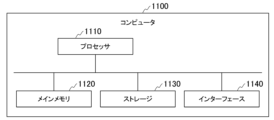
- FIG. 5 is a hardware configuration diagram showing the configuration of the computer 1100 according to this embodiment.
- Computer 1100 includes processor 1110 , main memory 1120 , storage 1130 and interface 1140 .
- the refrigerating cycle side controller 18 described above is implemented in the computer 1100 .
- the operation of each processing unit described above is stored in the storage 1130 in the form of a program.
- the processor 1110 reads a program from the storage 1130, develops it in the main memory 1120, and executes the above processing according to the program. Further, the processor 1110 secures storage areas corresponding to the storage units described above in the main memory 1120 according to the program.
- the program may be for realizing part of the functions that the computer 1100 exhibits.
- the program may function in combination with another program already stored in storage 1130 or in combination with another program installed in another device.
- the computer 1100 may include a custom LSI (Large Scale Integrated Circuit) such as a PLD (Programmable Logic Device) in addition to or instead of the above configuration.
- PLDs include PAL (Programmable Array Logic), GAL (Generic Array Logic), CPLD (Complex Programmable Logic Device), and FPGA (Field Programmable Gate Array).
- part or all of the functions implemented by processor 1110 may be implemented by the integrated circuit.
- Examples of the storage 1130 include magnetic disks, magneto-optical disks, and semiconductor memories.
- the storage 1130 may be an internal medium directly connected to the bus of the computer 1100, or an external medium connected to the computer 1100 via the interface 1140 or communication line.
- the computer 1100 receiving the delivery may develop the program in the main memory 1120 and execute the above process.
- storage 1130 is a non-transitory tangible storage medium.
- the program may be for realizing part of the functions described above.
- the program may be a so-called difference file (difference program) that implements the above-described functions in combination with another program already stored in the storage 1130 .
- the configuration in which the vehicle air conditioner 1 performs heating operation has been described as an example.
- a configuration similar to the form can be adopted.
- configurations of the vehicle-interior heat medium circuit 20 and the vehicle-exterior heat medium circuit 30 during cooling operation will be described with reference to FIG.
- the first pump 22 pumps the secondary refrigerant R2 heated by the condenser 13 to the outside heat exchanger 31 .
- a first heat medium line 20 a as a flow path for sucking the secondary refrigerant R ⁇ b>2 into the first pump 22 connects the condenser 13 and the first pump 22 .
- a second heat medium line 20b as a flow path for discharging the secondary refrigerant R2 from the first pump 22 toward the external heat exchanger 31 connects the first pump 22 and the first valve 23 .
- the first valve 23 allows the secondary refrigerant R2 discharged from the first pump 22 to flow through the fourth connection line 30i without flowing through the third heat medium line 20c.
- the secondary refrigerant R2 that has flowed into the fourth connection line 30i flows into the third valve 33 .
- the third valve 33 allows the secondary refrigerant R2 flowing from the fourth connection line 30i not to flow to the eleventh heat medium line 30d, but to the tenth heat medium line 30c.
- the secondary refrigerant R2 that has flowed into the tenth heat medium line 30c flows into the exterior heat exchanger 31 .
- the secondary refrigerant R2 that has passed through the external heat exchanger 31 flows into the fourth valve 34 via the ninth heat medium line 30b. Therefore, the flow direction of the secondary refrigerant R2 flowing through the tenth heat medium line 30c, the exterior heat exchanger 31, and the ninth heat medium line 30b during the cooling operation of the vehicle air conditioner 1 is the same as that during the heating operation. It is opposite to the flow direction of R2.
- the fourth valve 34 allows the secondary refrigerant R2 flowing from the ninth heat medium line 30b to flow not to the eighth heat medium line 30a but to the third connection line 30h.
- the secondary refrigerant R2 that has flowed into the third connection line 30h flows into the second valve 24 .
- the second valve 24 allows the secondary refrigerant R2 flowing from the third connection line 30h to flow through the fifth heat medium line 20e without flowing through the fourth heat medium line 20d.
- the secondary refrigerant R2 that has flowed into the fifth heat medium line 20e flows into the condenser 13 .
- the secondary refrigerant R2 flows through the condenser 13, the first pump 22, and the external heat exchanger 31 in sequence, and returns to the condenser 13.
- the heat exchange in the condenser 13 can continue to cool the primary refrigerant R1 circulating in the refrigeration cycle 10 .
- the second pump 32 pumps the secondary refrigerant R2 cooled by the evaporator 12 to the cooler core 21b.
- the secondary refrigerant R2 that has passed through the evaporator 12 due to the suction force of the pump flows into the eighth heat medium line 30a and into the fifth valve 35 .
- the fifth valve 35 allows the secondary refrigerant R2 flowing from the eighth heat medium line 30a to flow through both the sixth heat medium line 20f and the first connection line 30f.
- the secondary refrigerant R2 that has flowed into the sixth heat medium line 20f flows into the cooler core 21b.
- the secondary refrigerant R2 that has finished heat exchange in the cooler core 21b flows into the seventh heat medium line 20g and then into the second connection line 30g.
- the secondary refrigerant R2 that has flowed into the second connection line 30g flows into the eleventh heat medium line 30d and returns to the evaporator 12 via the second pump 32 and the twelfth heat medium line 30e.
- the secondary refrigerant R2 that has flowed into the first connection line 30f flows into the battery cooler 36. Therefore, the battery cooler 36 exchanges heat (is cooled) with the secondary refrigerant R2 during both the heating operation and the cooling operation of the vehicle air conditioner 1 .
- the secondary refrigerant R2 that has finished heat exchange in the battery cooler 36 flows into the second connection line 30g.
- the secondary refrigerant R2 that has flowed into the second connection line 30g flows into the eleventh heat medium line 30d and returns to the evaporator 12 via the second pump 32 and the twelfth heat medium line 30e.
- the secondary refrigerant R2 flows through the evaporator 12, the cooler core 21b, and the second pump 32 in sequence, and returns to the evaporator 12. By repeating this circulation, cooling operation is realized, and the temperature inside the vehicle can be kept cool.
- R290 refrigerant is exemplified as the primary refrigerant R1 and the ethylene glycol is exemplified as the secondary refrigerant R2 in the embodiment, other refrigerants may be used as the primary refrigerant R1 and the secondary refrigerant R2.
- the configuration in which the base plate 11 extends in the horizontal direction H has been described, but it is not limited to this configuration.
- the base plate 11 in the equipment housing space S may extend in a direction perpendicular to the horizontal direction H, and the main surface 11a of the base plate 11 may face the horizontal direction H.
- the casing 19 in the embodiment may be formed integrally with the vehicle body inner wall 200 and may be part of the vehicle body inner wall 200 .
- the vehicular refrigeration cycle unit 100 includes the casing 19 and the second scavenging port 52, the configuration may be such that they are not included.
- vehicle refrigeration cycle unit 100 in the embodiment may further include a leak sensor 17 provided below the compressor 14 and the condenser 13 in the second space S2 inside the casing 19 .
- the first scavenging port 51 is a hole formed in the side wall portion 202 of the vehicle body inner wall 200, but is not limited to this configuration, and the first scavenging port 51 is It may be a hole formed in the bottom wall portion 201 of the inner wall 200 of the vehicle body.
- the vehicle refrigeration cycle unit 100 is interposed between the vehicle exterior heat exchanger 31 and the vehicle interior heat exchanger 21, and separates the vehicle exterior heat exchanger 31 and the vehicle interior heat exchanger 21 from each other.
- a refrigerating cycle 10 having a compressor 14, a condenser 13, an expansion valve 16, and an evaporator 12; and a leakage sensor 17 capable of detecting the concentration of the primary refrigerant R1 contained in the atmosphere in the space S.
- the leak sensor 17 detects an increase in the concentration of the primary refrigerant R1.
- a vehicle refrigerating cycle unit 100 is the vehicle refrigerating cycle unit 100 of (1), in which the equipment housing space S communicates with the atmosphere outside the vehicle C.
- a scavenging port 51 and a fan 50 capable of discharging the atmosphere in the equipment housing space S to the atmosphere outside the vehicle C through the first scavenging port 51 may be further provided.
- the leaked primary refrigerant R1 can be positively discharged to the atmosphere without remaining in the equipment housing space S.
- a vehicle refrigeration cycle unit 100 according to a third aspect is the vehicle refrigeration cycle unit 100 of (2), in which the operation of the compressor 14 is stopped based on the detection information of the leak sensor 17.
- a control device for driving the fan 50 may be further provided.
- the primary refrigerant R1 in the equipment housing space S can be discharged to the atmosphere at the required timing, and the operation of the compressor 14 is stopped, so further leakage of the primary refrigerant R1 can be suppressed.
- a vehicle refrigeration cycle unit 100 according to a fourth aspect is the vehicle refrigeration cycle unit 100 of (2) or (3), in which the equipment An intake port 53 that communicates the accommodation space S with the atmosphere outside the vehicle C may be further provided.
- a vehicle refrigeration cycle unit 100 according to a fifth aspect is the vehicle refrigeration cycle unit 100 according to any one of (2) to (4), in which the equipment housing space S is located outside the first space S1. and a casing 19 that airtightly isolates the second space S2 inside and accommodates the compressor 14 and the condenser 13 in the second space S2, and the second space S1 without passing through the first space S1.
- a second scavenging port 52 that communicates the two spaces S2 and the atmosphere outside the vehicle C may further be provided.
- the primary refrigerant R1 leaks from the compressor 14 and the condenser 13
- the leaked primary refrigerant R1 can be retained in the second space S2 inside the casing 19, and the second space through the second scavenging port 52.
- the primary refrigerant R1 in S2 can be led to the atmosphere.
- a vehicular refrigeration cycle unit capable of grasping the presence or absence of leakage of the primary refrigerant.
- Vehicle air conditioner 10 Refrigeration cycle 11 Base plate 11a Main surface 12 Evaporator 12a, 13a Primary refrigerant inlet 12b, 13b Primary refrigerant outlet 12c, 13c Secondary refrigerant inlet 12d, 13d Secondary refrigerant outlet 13...Condenser 14...Compressor 15...Receiver 16...Expansion valve 17...Leakage sensor 18...Refrigerant cycle side controller 18a...Refrigerant concentration acquisition part 18b...Refrigerant concentration determination part 18c...Refrigeration cycle control part 18d Warning signal transmitter 19 Casing 19a Casing hole 20 Heating medium circuit inside vehicle 20a First heat medium line 20b Second heat medium line 20c Third heat medium line 20d Fourth heat medium line 20e Fifth heat medium line 20f...Sixth heat medium line 20g...Seventh heat medium line 21...In-car heat exchanger 21a...Heater core 21b...Cooler core 22...First pump 23...First valve 24...Second valve 30...Outside heat Medium circuit 30a...
- Main memory 1130... Storage 1140... Interface B ... Blower C... Vehicle Dv... Vertical direction F... Front grill H... Horizontal direction L... In-vehicle warning light
- R1 Primary refrigerant
- R2 Two Secondary refrigerant
Landscapes
- Physics & Mathematics (AREA)
- Thermal Sciences (AREA)
- Engineering & Computer Science (AREA)
- Mechanical Engineering (AREA)
- Air-Conditioning For Vehicles (AREA)
Abstract
Description
車両用空調装置は、電気自動車等に実装される装置であり、車体内の空気を調和する。この車両用空調装置によって、車体の内外の温度差が調整される。本実施形態では、車両用空調装置が暖房運転する場合の構成を一例として説明する。
なお、図面では、これら車両用冷凍サイクルユニット100、車内側熱媒回路20、及び車外側熱媒回路30が有する各種ライン(配管)のうち、冷媒が流通可能な開通状態にあるラインを実線で示し、冷媒が流通不可能な閉止状態にあるラインを破線で示している。また、各種バルブは、黒塗りであれば閉塞状態を、白塗りであれば開放状態を示している。
車両用冷凍サイクルユニット100は、車両内空調に用いられる二次冷媒R2と熱交換させるための一次冷媒R1を流通させる装置である。本実施形態における一次冷媒R1には、例えば比重が空気よりも大きい強燃性(可燃性)の炭化水素であるR290冷媒(プロパン)が採用される。
ベースプレート11は、機器収容空間S内に設けられている平板状を成す部材である。ベースプレート11は、重力方向に一致する方向である上下方向Dvの上方側を向く主面11aを有している。言い換えれば、ベースプレート11は、主面11aが上方を向くように上下方向Dvと垂直な方向である水平方向Hに延びている。ベースプレート11を構成する材料には、例えば金属や合成樹脂等が採用される。
冷凍サイクル10は、熱力学サイクルを実現する複数の装置によって構成されている。冷凍サイクル10は、熱媒体としての一次冷媒R1を二次冷媒R2と熱交換させるために、この一次冷媒R1を繰り返し圧縮及び膨張、並びに蒸発及び凝縮させながら複数の装置内を順次に流通させるとともに循環させる冷媒回路である。
蒸発器12は、冷凍サイクル10を順次流通する一次冷媒R1と、車両用冷凍サイクルユニット100の外部から導入される二次冷媒R2とを熱交換させることで、この一次冷媒R1を蒸発(気化)させるプレート式熱交換器である。蒸発器12内部における一次冷媒R1は、二次冷媒R2によって温められると同時に、二次冷媒R2を冷やす。図2では便宜上明示しないが、蒸発器12は、ベースプレート11の主面11aに固定されている。
圧縮機14は、蒸発器12を経由することで気化した一次冷媒R1を圧縮する装置である。圧縮機14に導入された一次冷媒R1の圧力は、圧縮機14の圧縮によって圧縮前よりも高い所定の圧力まで高められる。これによって、一次冷媒R1の温度は、圧縮前よりも上昇する。図2では便宜上明示しないが、圧縮機14はベースプレート11の主面11aに固定されている。
凝縮器13は、圧縮機14を経由することで圧縮される前よりも高温高圧となった一次冷媒R1と、車両用冷凍サイクルユニット100の外部から導入される二次冷媒R2とを熱交換させることで、この一次冷媒R1を凝縮(液化)させるプレート式熱交換器である。凝縮器13内部における一次冷媒R1は、二次冷媒R2によって冷やされると同時に、二次冷媒R2を温める。図2では便宜上明示しないが、凝縮器13は、ベースプレート11の主面11aに固定されている。
レシーバ15は、凝縮器13を経由することで気液混合状態の流体となった一次冷媒R1を受け入れて、この一次冷媒R1を気相と液相とに分離するとともにこれらを一時的に内部に保持する気液分離器である。
膨張弁16は、レシーバ15を経由することで液体状態となった一次冷媒R1を受け入れて、この一次冷媒R1を断熱膨張させる装置である。膨張弁16とレシーバ15とは、膨張前ライン136の第二ライン156によって接続されている。即ち、第二ライン156の一端は、レシーバ15の冷媒出口部に接続されており、第二ライン156の他端は、膨張弁16に接続されている。
ケーシング19は、機器収容空間Sを外側の第一空間S1と内側の第二空間S2とに気密に隔離するとともに、圧縮機14、及び凝縮器13を第二空間S2に収容している。即ち、第一空間S1と第二空間S2とは、ケーシング19によって入れ子の関係になっている。ケーシング19は、ベースプレート11の主面11aに固定されている。
漏洩センサ17は、収容空間内の雰囲気に含まれる一次冷媒R1の濃度を検知可能なガスセンサである。漏洩センサ17は、機器収容空間S内に設けられており、冷凍サイクル10の圧縮機14、凝縮器13、及び蒸発器12よりも下方(上下方向Dv下方側)に位置している。具体的には、漏洩センサ17は、底壁部201が有する底面に設けられている。漏洩センサ17は、所定の時間間隔で収容空間内の雰囲気に含まれる一次冷媒R1の濃度を検知するとともに、ケーブル(ワイヤハーネス)等を通じてこの濃度を示す信号を外部へ送信する。
第一掃気口51は、機器収容空間Sと車両Cの外側の大気とを連通させる空気流路である。第一掃気口51は、冷凍サイクル10の圧縮機14、凝縮器13、及び蒸発器12よりも下方に位置している。本実施形態における第一掃気口51は、車体内壁200の側壁部202に形成されている孔部である。
ファン50は、機器収容空間S内の雰囲気を、第一掃気口51を通じて車両Cの外側の大気に排出可能なファン50である。ファン50は、第一掃気口51に設けられている。即ち、本実施形態におけるファン50は、機器収容空間Sのうち第一空間S1内の雰囲気を車両Cの外側へ送気する。
吸気口53は、第一掃気口51とは独立して機器収容空間Sと車両Cの外側の大気とを連通させる空気流路である。吸気口53は、冷凍サイクル10の圧縮機14、凝縮器13、及び蒸発器12よりも上方(上下方向Dv上方側)に位置している。本実施形態における吸気口53は、例えば、ボンネット203に形成される孔部である。なお、吸気口53は、ボンネット203と側壁部202との隙間に区画されるギャップであってもよい。
第二掃気口52は、ケーシング19に形成されたケーシング孔19aと車体内壁200に形成された孔部60との組み合わせによって構成されている。即ち、第二掃気口52は、第一空間S1を経由せずにケーシング19内側の第二空間S2と車両Cの外側の大気とを連通させる空気流路である。
冷凍サイクル側制御装置18は、漏洩センサ17の検知情報に基づいて、冷凍サイクル10の圧縮機14の運転を停止させるとともに、ファン50を駆動させる装置である。
冷媒濃度判定部18bは、冷媒濃度取得部18aが取得した一次冷媒R1の濃度に基づいて機器収容空間S内で一次冷媒R1が漏洩しているか否かを判定する。具体的には、冷媒濃度判定部18bは、冷媒濃度取得部18aが取得した一次冷媒R1の濃度が所定の閾値以上であるか否かを判定する。
したがって、本実施形態における安全濃度範囲は、0%以上2.1%未満である。
ファン50は、冷凍サイクル制御部18cからの駆動開始の指示を示す信号を受け付けたら駆動する。つまり、ファン50は、機器収容空間S内の雰囲気を、第一掃気口51を通じて大気に向かって送気し始める。
続いて、冷凍サイクル側制御装置18の動作について図4を参照して説明する。
冷媒濃度判定部18bが漏洩していると判定した場合(ステップS1;YES)、冷凍サイクル制御部18cは、運転停止の指示を示す信号を圧縮機14に送信する。即ち、冷凍サイクル制御部18cは、圧縮機14の運転を停止させる(ステップS2)。
一方で、冷媒濃度判定部18bが漏洩していないと判定した場合(ステップS1;NO)、ステップS1の処理に戻る。
警告を示す信号が車両側制御装置40に送信された後、冷凍サイクル制御部18cは、駆動開始の指示を示す信号をファン50に送信する。即ち、冷凍サイクル制御部18cは、ファン50を駆動させる(ステップS4)。
一方で、一次冷媒R1の濃度が安全濃度範囲内でないと判定された場合(ステップS5;NO)、ステップS4の処理に戻る。
車内側熱媒回路20は、冷凍サイクル10で一次冷媒R1と熱交換した二次冷媒R2を流通させるとともに、車内の空気を調和させるための冷媒回路である。本実施形態における二次冷媒R2には、例えばエチレングリコール等の不凍液が採用される。
車外側熱媒回路30は、冷凍サイクル10で一次冷媒R1と熱交換した二次冷媒R2を流通させるとともに、車体駆動用のバッテリーを冷却するための冷媒回路である。
車外側熱媒回路30は、車外熱交換器31と、第二ポンプ32と、各種バルブ(第三バルブ33及び第五バルブ35)と、バッテリー冷却器36と、各種ライン(第八熱媒ライン30a~第十二熱媒ライン30e、及び第一接続ライン30f~第四接続ライン30i)と、を有している。
上記実施形態に係る車両用冷凍サイクルユニット100は、圧縮機14、凝縮器13、膨張弁16、及び蒸発器12よりも下方で、機器収容空間S内雰囲気の一次冷媒R1の濃度を検知可能な漏洩センサ17を備えている。これにより、圧縮機14、凝縮器13、及び蒸発器12の何れかに異常が生じて一次冷媒R1が漏洩した際、漏洩した一次冷媒R1は下降すると、漏洩センサ17によって一次冷媒R1の濃度の上昇が検知される。したがって、漏洩センサ17の検知した濃度に基づいて、一次冷媒R1の漏洩の有無を把握することができる。
また、ケーシング19によって機器収容空間Sが第一空間S1と第二空間S2とに区画されるため、冷凍サイクル10が有する何れの装置から一次冷媒R1が漏洩したのかを特定することができる。
以上、本開示の実施形態について図面を参照して詳述したが、具体的な構成は実施形態の構成に限られるものではなく、本開示の要旨を逸脱しない範囲内での構成の付加、省略、置換、及びその他の変更が可能である。また、本開示は実施形態によって限定されることはなく、請求の範囲によってのみ限定される。
コンピュータ1100は、プロセッサ1110、メインメモリ1120、ストレージ1130、インターフェース1140を備える。
以下、図6を参照して冷房運転時における車内側熱媒回路20及び車外側熱媒回路30の構成を説明する。
上記実施形態に記載の車両用冷凍サイクルユニットは、例えば以下のように把握される。
Claims (5)
- 車外熱交換器及び車内熱交換器の間に介在されて、これら車外熱交換器と車内熱交換器とをそれぞれ流通する二次冷媒同士の熱交換をする車両用冷凍サイクルユニットであって、
車両の内側における機器収容空間内に設けられ、比重が空気より大きい可燃性の一次冷媒が順次流通する圧縮機、凝縮器、膨張弁、及び蒸発器を有する冷凍サイクルと、
前記圧縮機、前記凝縮器、及び前記蒸発器よりも下方に位置するとともに、前記機器収容空間内の雰囲気に含まれる前記一次冷媒の濃度を検知可能な漏洩センサと、
を備える車両用冷凍サイクルユニット。 - 前記機器収容空間と前記車両の外側の大気とを連通させる第一掃気口と、
前記機器収容空間内の前記雰囲気を、前記第一掃気口を通じて前記車両の外側の前記大気に排出可能なファンと、
を更に備える請求項1に記載の車両用冷凍サイクルユニット。 - 前記漏洩センサの検知情報に基づいて、前記圧縮機の運転を停止させるとともに、前記ファンを駆動させる制御装置を更に備える請求項2に記載の車両用冷凍サイクルユニット。
- 前記第一掃気口とは独立して、前記機器収容空間と前記車両の外側の前記大気とを連通させる吸気口を更に備える請求項2又は3に記載の車両用冷凍サイクルユニット。
- 前記機器収容空間を外側の第一空間と内側の第二空間とに気密に隔離するとともに、前記圧縮機、及び前記凝縮器を前記第二空間に収容するケーシングと、
前記第一空間を経由せずに前記第二空間と前記車両の外側の前記大気とを連通させる第二掃気口と、
を更に備える請求項2から4の何れか一項に記載の車両用冷凍サイクルユニット。
Priority Applications (5)
| Application Number | Priority Date | Filing Date | Title |
|---|---|---|---|
| CN202180103586.2A CN118215588A (zh) | 2021-11-04 | 2021-11-04 | 车辆用制冷循环单元 |
| US18/704,340 US20240416723A1 (en) | 2021-11-04 | 2021-11-04 | Vehicular refrigeration cycle unit |
| JP2023557506A JP7774637B2 (ja) | 2021-11-04 | 2021-11-04 | 車両用冷凍サイクルユニット |
| DE112021008430.5T DE112021008430T5 (de) | 2021-11-04 | 2021-11-04 | Fahrzeugkühlkreislaufeinheit |
| PCT/JP2021/040632 WO2023079643A1 (ja) | 2021-11-04 | 2021-11-04 | 車両用冷凍サイクルユニット |
Applications Claiming Priority (1)
| Application Number | Priority Date | Filing Date | Title |
|---|---|---|---|
| PCT/JP2021/040632 WO2023079643A1 (ja) | 2021-11-04 | 2021-11-04 | 車両用冷凍サイクルユニット |
Publications (1)
| Publication Number | Publication Date |
|---|---|
| WO2023079643A1 true WO2023079643A1 (ja) | 2023-05-11 |
Family
ID=86240813
Family Applications (1)
| Application Number | Title | Priority Date | Filing Date |
|---|---|---|---|
| PCT/JP2021/040632 Ceased WO2023079643A1 (ja) | 2021-11-04 | 2021-11-04 | 車両用冷凍サイクルユニット |
Country Status (5)
| Country | Link |
|---|---|
| US (1) | US20240416723A1 (ja) |
| JP (1) | JP7774637B2 (ja) |
| CN (1) | CN118215588A (ja) |
| DE (1) | DE112021008430T5 (ja) |
| WO (1) | WO2023079643A1 (ja) |
Cited By (4)
| Publication number | Priority date | Publication date | Assignee | Title |
|---|---|---|---|---|
| CN119283563A (zh) * | 2024-09-12 | 2025-01-10 | 中国第一汽车股份有限公司 | 车辆制冷系统、制冷剂泄漏应对方法以及车辆 |
| WO2025203910A1 (ja) * | 2024-03-29 | 2025-10-02 | トヨタ自動車株式会社 | 車両 |
| WO2025228858A1 (fr) * | 2024-05-03 | 2025-11-06 | Ampere S.A.S. | Dispositif de management thermique d'un véhicule électrique |
| FR3163609A1 (fr) * | 2024-06-21 | 2025-12-26 | Ampere Sas | Dispositif de management thermique d’un véhicule comportant une chaine de traction électrique |
Families Citing this family (3)
| Publication number | Priority date | Publication date | Assignee | Title |
|---|---|---|---|---|
| CN115493250A (zh) * | 2022-11-01 | 2022-12-20 | 叁九科技(杭州)有限公司 | 一种空调系统中冷媒泄露检测系统及其控制方法 |
| JP2026068805A (ja) * | 2024-10-11 | 2026-04-23 | トヨタ自動車株式会社 | 車載空調装置 |
| DE102024130329A1 (de) * | 2024-10-18 | 2026-04-23 | Bayerische Motoren Werke Aktiengesellschaft | Kühl- und Heizsystem für ein Fahrzeug und Betriebsverfahren für ein Kühl- und Heizsystems eines Fahrzeugs |
Citations (4)
| Publication number | Priority date | Publication date | Assignee | Title |
|---|---|---|---|---|
| WO2000034065A1 (fr) * | 1998-12-04 | 2000-06-15 | Zexel Valeo Climate Control Corporation | Dispositif de securite pour vehicules |
| JP2006078090A (ja) * | 2004-09-09 | 2006-03-23 | Sanden Corp | 冷凍装置 |
| JP2007010227A (ja) * | 2005-06-30 | 2007-01-18 | Sanden Corp | 車両用空調装置 |
| JP2008032389A (ja) * | 2007-10-11 | 2008-02-14 | Matsushita Refrig Co Ltd | 自動販売機 |
Family Cites Families (18)
| Publication number | Priority date | Publication date | Assignee | Title |
|---|---|---|---|---|
| JP3414464B2 (ja) * | 1993-12-09 | 2003-06-09 | 松下電器産業株式会社 | 空気調和機 |
| JP3407441B2 (ja) * | 1994-12-20 | 2003-05-19 | 松下電器産業株式会社 | 除湿機 |
| JPH11301254A (ja) * | 1998-04-16 | 1999-11-02 | Tgk Co Ltd | 自動車用空調装置 |
| FR2808738B1 (fr) * | 2000-05-15 | 2002-08-23 | Peugeot Citroen Automobiles Sa | Dispositif de regulation thermique perfectionne a pompe a chaleur pour vehicule automobile |
| WO2002027245A1 (fr) * | 2000-09-26 | 2002-04-04 | Daikin Industries, Ltd. | Climatiseur |
| US7107786B2 (en) * | 2004-11-12 | 2006-09-19 | Tecumseh Products Company | Apparatus for and method of venting hydrocarbon refrigerant leaks |
| JP2011161970A (ja) * | 2010-02-05 | 2011-08-25 | Sanden Corp | 車両用空調装置 |
| US8899062B2 (en) * | 2011-02-17 | 2014-12-02 | Delphi Technologies, Inc. | Plate-type heat pump air conditioner heat exchanger for a unitary heat pump air conditioner |
| JP5916360B2 (ja) * | 2011-11-30 | 2016-05-11 | 三菱重工業株式会社 | ターボ冷凍機 |
| JP6089357B2 (ja) * | 2012-06-29 | 2017-03-08 | パナソニックIpマネジメント株式会社 | 車両用ヒートポンプ装置 |
| JP6064753B2 (ja) * | 2013-04-05 | 2017-01-25 | 株式会社デンソー | 車両用熱管理システム |
| WO2018147428A1 (ja) * | 2017-02-09 | 2018-08-16 | ダイキン工業株式会社 | 冷凍装置 |
| US20200047591A1 (en) * | 2017-04-27 | 2020-02-13 | Ford Global Technologies, Llc | Vehicle heating and cooling system and control method |
| US20210213802A1 (en) * | 2018-07-30 | 2021-07-15 | Carrier Corporation | Ventilation system provided with a refrigerated container |
| US10731884B2 (en) * | 2018-10-29 | 2020-08-04 | Johnson Controls Technology Company | Refrigerant leak management systems |
| US12405015B2 (en) * | 2021-06-29 | 2025-09-02 | Samsung Electronics Co., Ltd. | Dehumidification apparatus and dehumidification method using the same |
| KR20230034711A (ko) * | 2021-09-03 | 2023-03-10 | 현대자동차주식회사 | 차량의 열관리 시스템 |
| KR20250068385A (ko) * | 2023-11-09 | 2025-05-16 | 현대자동차주식회사 | 차량 열관리시스템 |
-
2021
- 2021-11-04 JP JP2023557506A patent/JP7774637B2/ja active Active
- 2021-11-04 US US18/704,340 patent/US20240416723A1/en active Pending
- 2021-11-04 DE DE112021008430.5T patent/DE112021008430T5/de active Pending
- 2021-11-04 WO PCT/JP2021/040632 patent/WO2023079643A1/ja not_active Ceased
- 2021-11-04 CN CN202180103586.2A patent/CN118215588A/zh not_active Withdrawn
Patent Citations (4)
| Publication number | Priority date | Publication date | Assignee | Title |
|---|---|---|---|---|
| WO2000034065A1 (fr) * | 1998-12-04 | 2000-06-15 | Zexel Valeo Climate Control Corporation | Dispositif de securite pour vehicules |
| JP2006078090A (ja) * | 2004-09-09 | 2006-03-23 | Sanden Corp | 冷凍装置 |
| JP2007010227A (ja) * | 2005-06-30 | 2007-01-18 | Sanden Corp | 車両用空調装置 |
| JP2008032389A (ja) * | 2007-10-11 | 2008-02-14 | Matsushita Refrig Co Ltd | 自動販売機 |
Cited By (5)
| Publication number | Priority date | Publication date | Assignee | Title |
|---|---|---|---|---|
| WO2025203910A1 (ja) * | 2024-03-29 | 2025-10-02 | トヨタ自動車株式会社 | 車両 |
| WO2025228858A1 (fr) * | 2024-05-03 | 2025-11-06 | Ampere S.A.S. | Dispositif de management thermique d'un véhicule électrique |
| FR3161878A1 (fr) * | 2024-05-03 | 2025-11-07 | Ampere Sas | Dispositif de management thermique d’un véhicule électrique. |
| FR3163609A1 (fr) * | 2024-06-21 | 2025-12-26 | Ampere Sas | Dispositif de management thermique d’un véhicule comportant une chaine de traction électrique |
| CN119283563A (zh) * | 2024-09-12 | 2025-01-10 | 中国第一汽车股份有限公司 | 车辆制冷系统、制冷剂泄漏应对方法以及车辆 |
Also Published As
| Publication number | Publication date |
|---|---|
| JPWO2023079643A1 (ja) | 2023-05-11 |
| US20240416723A1 (en) | 2024-12-19 |
| JP7774637B2 (ja) | 2025-11-21 |
| DE112021008430T5 (de) | 2024-08-14 |
| CN118215588A (zh) | 2024-06-18 |
Similar Documents
| Publication | Publication Date | Title |
|---|---|---|
| JP7774637B2 (ja) | 車両用冷凍サイクルユニット | |
| JP5659925B2 (ja) | 車両用空調装置 | |
| AU2010364873B2 (en) | Air-conditioning apparatus | |
| CN110345281A (zh) | 用于调节流体循环回路中的流体的分配和流量的设备 | |
| US9796246B2 (en) | Vehicle heat pump device, and vehicle air-conditioning device | |
| JP6521049B2 (ja) | 除霜機能をもつヒートポンプ装置 | |
| CN105121192B (zh) | 车辆用热管理系统 | |
| CN101547803A (zh) | 车辆用空调系统 | |
| CN112424006B (zh) | 车辆用空调装置 | |
| WO2013136693A1 (ja) | 冷凍サイクル装置 | |
| JP6075058B2 (ja) | 冷凍サイクル装置 | |
| JP2015030289A (ja) | 車両用熱管理システム | |
| JP2012144245A (ja) | 熱交換システム | |
| JPH11286211A (ja) | 車両用空調装置 | |
| CN113386526A (zh) | 一种间接式热泵空调系统、控制方法及纯电动汽车 | |
| JP2014225346A (ja) | 電池温度調整ユニット | |
| CN107791780B (zh) | 汽车空调系统 | |
| US20180306453A1 (en) | Air-Conditioning Device, in particular for a Rail Vehicle | |
| JP2013148229A (ja) | 気液分離器及び車両用空気調和装置 | |
| CN108973585A (zh) | 具有并联热交换器的车辆加热和冷却系统以及控制方法 | |
| JP2024055286A (ja) | 車両用温調システム | |
| KR20160009779A (ko) | 차량용 냉난방시스템 | |
| CN107791781B (zh) | 汽车空调系统 | |
| JP5510374B2 (ja) | 熱交換システム | |
| JP6232592B2 (ja) | 車両用ヒートポンプ装置および車両用空調装置 |
Legal Events
| Date | Code | Title | Description |
|---|---|---|---|
| 121 | Ep: the epo has been informed by wipo that ep was designated in this application |
Ref document number: 21963239 Country of ref document: EP Kind code of ref document: A1 |
|
| ENP | Entry into the national phase |
Ref document number: 2023557506 Country of ref document: JP Kind code of ref document: A |
|
| WWE | Wipo information: entry into national phase |
Ref document number: 202180103586.2 Country of ref document: CN |
|
| WWE | Wipo information: entry into national phase |
Ref document number: 18704340 Country of ref document: US |
|
| WWE | Wipo information: entry into national phase |
Ref document number: 112021008430 Country of ref document: DE |
|
| 122 | Ep: pct application non-entry in european phase |
Ref document number: 21963239 Country of ref document: EP Kind code of ref document: A1 |